Embed Size (px)
Citation preview
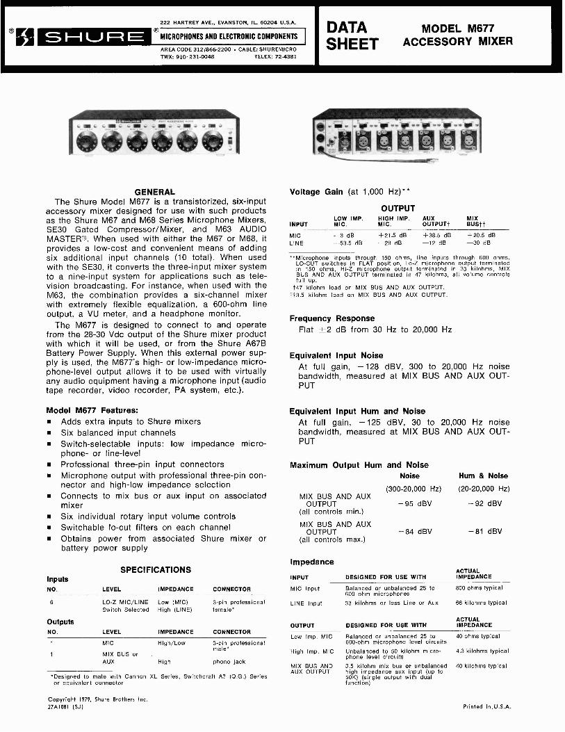
222 HARTREY AVE.. EVANSTON, IL. 60204 U.S.A. Q MODEL M677
AREA CODE 312/866-2200 . CABLE: SHUREMICRO I :iEtT ACCESSORY MIXER TWX: 910-231-0048 TELEX: 72-4381 I
GENERAL The Shure Model M677 is a transistorized, six-input
accessory mixer designed for use with such products as the Shure M67 and M68 Series Microphone Mixers, SE30 Gated Compressor/Mixer, and M63 AUDIO MASTER@. When used with either the M67 or M68, it provides a low-cost and convenient means of adding six additional input channels (10 total). When used with the SE30, it converts the three-input mixer system to a nine-input system for applications such as tele- vision broadcasting. For instance, when used with the M63, the combination provides a six-channel mixer with extremely flexible equalization, a 600-ohm line output, a VU meter, and a headphone monitor.
The M677 is designed to connect to and operate from the 28-30 Vdc output of the Shure mixer product with which it will be used, or from the Shure A67B Battery Power Supply. When this external power sup- ply is used, the M677's high- or low-impedance micro- phone-level output allows it to be used with virtually any audio equipment having a microphone input (audio tape recorder, video recorder, PA system, etc.).
Model M677 Features: H Adds extra inputs to Shure mixers H Six balanced input channels H Switch-selectable inputs: low impedance micro-
phone- or line-level H Professional three-pin input connectors H Microphone output with professional three-pin con-
nector and high-low impedance selection H Connects to mix bus or aux input on associated
mixer H Six individual rotary input volume controls H Switchable lo-cut filters on each channel H Obtains power from associated Shure mixer or
battery power supply
SPECIFICATIONS Inputs NO. LEVEL IMPEDANCE CONNECTOR
LO-Z MIC/LINE Low (MIC) 3-pin professional Switch Selected High (LINE) female*
Outputs NO. LEVEL IMPEDANCE CONNECTOR
MIC High/Low 3-pin professional male*
MIX BUS or AUX High phono jack
*Designed to mate with Cannon XL Series, Switchcraft A3 (Q .G . ) Series or equivalent connector
Voltage Gain (at 1,000 Hz)* *
OUTPUT LOW IMP. HIGH IMP. AUX MIX
INPUT MIC. MIC. OUTPUTt B U S t i --
MIC -3 dB t 2 1 . 5 dB + 38.5 dB +20.5 dB LINE -53.5 dB -29 dB -12 dB -30 dB
"Microphone inputs through 150 ohms, line inputs through 600 ohms, LO-CUT switches in FLAT position, Lo-Z microphone output terminated In 150 ohms, Hi-Z microphone output terminated in 33 kilohms, MIX BUS AND AUX OUTPUT terminated in 47 kilohms, al l volume controls fu l l up.
t47 kllohm load on MIX BUS AND AUX OUTPUT. t t3.5 kilohm load on MIX BUS AND AUX OUTPUT
Frequency Response Flat - t2 dB from 30 Hz to 20.000 Hz
Equivalent lnput Noise At full gain, -128 dBV, 300 to 20,000 Hz noise bandwidth, measured at MIX BUS AND AUX OUT- PUT
Equivalent lnput Hum and Noise At full gain, -125 dBV, 30 to 20,000 Hz noise bandwidth, measured at MIX BUS AND AUX OUT- PUT
Maximum Output Hum and Noise Noise Hum & Noise
--
(300-20,000 Hz) (20-20,000 Hz) MIX BUS AND AUX
OUTPUT -95 dBV -92 dBV (all controls min.)
MIX BUS AND AUX OUTPUT -84 dBV -81 dBV
(all controls max.)
Impedance ACTUAL
INPUT DESIGNED FOR USE WITH IMPEDANCE
MIC Input Balanced or unbalanced 25 to 800 ohms typical 600 ohm microphones
LINE Input 33 kilohms or less Line or Aux 66 kilohms typical
ACTUAL OUTPUT DESIGNED FOR USE WITH IMPEDANCE
Low Imp. MIC Balanced or unbalanced 25 to 40 ohms typical 600-ohm microphone level circuits
High Imp. MIC Unbalanced to 50 kilohm micro- 4.3 kilohms typical phone level circuits
MIX BUS AND 3.5 kilohm mix bus or unbalanced 40 kilohms typical AUX OUTPUT high ~mpedance aux input (up to
50K) (single output with dual function)
Copyright 1979, Shure Brothers Inc. 27AlO8l (SJ) Printed in.U.S.A.
Distortion Less than 1 % Total Harmonic Distortion at 1,000 Hz when Low lmpedance Microphone Output is at 20 mV level, High lmpedance Microphone Output is at 300 mV level, and MIX BUS AND AUX OUTPUT is at 2V level (loaded with 47 kilohms).
lnput Clipping Level Minimum Clipping Level
Low lmpedance Microphone Input 25 mV (-32 dBV)
Line Input lOV (+20 dBV)
Minimum Common Mode Rejection 110 dB with microphone input of 10V at 100 Hz
Output Clipping Level Minimum Clipping Level
Low lmpedance Microphone Output 25 mV (-32 dBV)
High Impedance Microphone Output 0.4V ( - 8 dBV)
Mix Bus and 0.4V ( - 8 dBV) (3.5K load) Aux Output 3V ( + 10 dBV) (47K load)
Phase The Mix Bus and Aux, and Microphone Level (High Impedance) Outputs are in phase with pin 3 of each input connector. The Microphone Level (Low Imped- ance) Output is in phase with each input.
Lo-Cut Filters - 6 dB at 100 Hz typical
Volume Controls All audio taper
Operating Voltage 27 Vdc, 6.0 t 2 mA. (Meets all specifications except clipping levels at any voltage from 20 to 34 Vdc)
Temperature Range Operating: -7" to 57°C (20" to 135°F) Storage: -29" to 71 "C (-20" to 160°F)
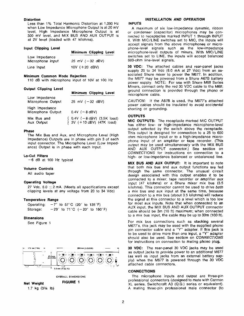
Dimensions See Figure 1
OVERALL DIMENSIONS
Net Weight FIGURE 1
1.7 kg (3% lb)
INSTALLATION AND OPERATION INPUTS
A maximum of six low-impedance dynamic, ribbon or condenser (capacitor) microphones may be con- nected to receptacles marked INPUT 1 through INPUT 6. With MICILINE switches set to MIC, the inputs will accept signals from the above microphones or micro- phone-level signals such as the low-impedance microphone-level outputs of mixers. With MICILINE switches set to LINE, the inputs will accept balanced 600-ohm line-level signals.
30 VDC: The attached cables and rear-panel jacks supply 20 to 34 Vdc (6.0 mA at 27 Vdc) from an as- sociated Shure mixer to power the M677. In addition, the M677 may be powered from a Shure A67B battery power supply. NOTE: For use with Shure M68 Series Mixers, connect only the red 30 VDC cable to the M68; ground connection is provided through the phono or microphone cable.
CAUTION: If the A678 is used, the M677's attached power cables should be insulated to avoid accidental shorting or grounding.
OUTPUTS MIC OUTPUTS: The receptacle marked MIC OUTPUT has either low- or high-impedance microphone-level output selected by the switch above the receptacle. This output is designed for connection to a 25 to 600 ohm microphone input or to a high-impedance micro- phone input of an amplifier or tape recorder. (This output may be used simultaneously with the MIX BUS AND AUX OUTPUT connector.) See section on CONNECTIONS for instructions on connection to a high- or low-impedance balanced or unbalanced line.
MIX BUS AND AUX OUTPUT: It is important to note that both mix bus and aux output functions are fed through the same connector. The unusual circuit design associated with this output enables it to be connected to a mixer, tape recorder or amplifier aux input (47 kilohms) or a Shure mixer mix bus (3.5 kilohms). This connector cannot be used to drive both a mix bus and aux input at the same time, because connection to a mix bus (about 3.5 kilohms) will reduce the signal at this connector to a level which is too low for most aux inputs. Note that when connected to an AUX input, the MIX BUS AND AUX OUTPUT connector cable should be 3m (10 ft) maximum; when connected to a mix bus input, the cable may be up to 30m (100 ft).
For mix bus connections such as stacking several M677's, this jack may be used with the supplied phono pin connector cable and a "Y" adapter. If this jack is to be used to drive more than one input, a "Y" adapter should also be used. See section on CONNECTIONS for instructions on connection to mating phono plug.
30 VDC: The rear-panel 30 VDC jacks may be used as output jacks to provide power to an additional M677 (as well as input jacks from an external battery sup- ply) when the M677 is powered through the 30 VDC attached cable connectors.
CONNECTIONS The microphone inputs and output are three-pin
professional connectors (designed to mate with Cannon XL series, Switchcraft A3 (Q.G.) series or equivalent). A mating three-pin professional male connector (to

mate with microphone INPUT) may be ordered directly from Shure Brothers Inc. as Shure Part RK121P. A mating three-pin professional female connector (to mate with MIC OUTPUT) may be ordered directly from Shure Brothers Inc. as Shure Part RK120P.
For microphone- or line-level balanced-line connec- tions to these inputs and output, use two-conductor shielded cable with the shield to pin 1, and two "hot" leads to pins 2 and 3. For unbalanced-line low-imped- ance connections, use single-conductor shielded cable with the shield to pins 1 and 2, and the "hot" lead to pin 3. For high-impedance microphone output or line-level input connections (unbalanced only), use single-conductor shielded cable with the shield to pin 1 and the "hot" lead to pin 3. See Figure 2 for illustra- tion of these alternatives.
MIC OR LINE (BALANCED LINEI
LOW IMPEDANCE MIC
(UNBALANCED LINE)
HIGH IMPEDANCE OUT OR L INE- LEVEL INPUT
(UNBALANCED LINEI
MICROPHONE CONNECTIONS
FIGURE 2
The MIX BUS AND AUX OUTPUT is a phono pin jack. A 305 mm (12 in.) long interconnecting cable (single-conductor shielded with a phono pin plug on each end) is supplied with the M677. Note that the "hot" lead is connected to the phono pin plug tip and the shield to the shell. "Y" connections may be made to phono pin plugs used in the MIX BUS AND AUX OUTPUT jack when M677s are stacked.
OPERATION
POWER ON-OFF Switch: Activate POWER ON-OFF switch to turn the M677 on. Note that power supplied by the associated Shure mixer is present at the 30 VDC jacks whether the M677 POWER switch is on or off.
MIC/LINE Selector Switches: Set individual channel MICILINE switches for microphone- or line-level in- puts as desired.
Volume Controls: The individual volume controls for each of the six channels are identified on the front panel. Volume controls for individual channels not being used should be kept at minimum setting (fully counterclockwise). For maximum signal-to-noise ratio, the volume controls in use should be set to the highest position possible without incurring overload distortion.
LO-CUT Filter Switches: Activate individual channel LO-CUT filter switches as desired to reduce low-fre- quency response (approximately 6 dB at 100 Hz).
Operation with Shure Mixers: Connect the 30 VDC power leads of the M677 to the auxiliary power output jacks of the "master" unit (Shure M67 or M68 Micro- phone Mixer, SE30 Gated Compressor/Mixer, or M63 AUDIO MASTER@). Connect the M677 MIX BUS AND AUX OUTPUT to the mix bus or aux input of the master unit. This connection will result in a total of 10 inputs for the M67 or M68 (the aux volume control of the M68 may be used as a submaster control for the M677 in- puts), nine inputs for the SE30, or six inputs (with tone control capability) for the M63. If a submaster function is desired for the M67 or SE30, the M677 MIC OUTPUT connector may be connected to a microphone input on the master unit. The channel volume control becomes a submaster control for the M677 output. Make certain the M677 HI-LO IMPED- ANCE switch is set to match the microphone input of the master unit.
GUARANTEE This Shure product is guaranteed in normal use to
be free from electrical and mechanical defects for a period of one year from date of purchase. Please retain proof of purchase date. This guarantee includes all parts and labor. This guarantee is in lieu of any and all other guarantees or warranties, express or implied, and there shall be no recovery for any con- sequential or incidental damages.
SHIPPING INSTRUCTIONS Carefully repack the unit and return it prepaid to:
Shure Brothers Incorporated Attention: Service Department 1501 West Shure Drive Arlington Heights, Illinois 60004
If outside the United States, return the unit to your dealer or Authorized Shure Service Center for repair. The unit will be returned to you prepaid.
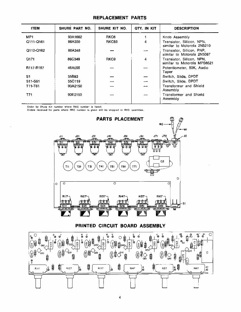
REPLACEMENT PARTS
Order by Shure Kit number where RKC number is listed. Orders received for parts where RKC number is given will be shipped in RKC quantities.
ITEM
MPI Q111-Q161
Q112-Q162
Q171
R117-R167
S 1 S11-S61 T I 1-T61
T71
PARTS PLACEMENT
W I
J2
0 0 0
PRINTED CIRCUIT BOARD ASSEMBLY
SHURE PART NO.
90A1662 86A350
86A348
86C349
46A055
55883 55C119 90A2150
90E2150
SHURE KIT NO.
RKC6 RKC89
-
R KC9
-
- - -
-
QTY. IN KIT
1 4
-
4
-
- - -
-
DESCRIPTION
Knob Assembly Transistor, Silicon, NPN, similar to Motorola 2N5210 Transistor, Silicon, PNP, similar to Motorola 2N5087 Transistor, Silicon, NPN, similar to Motorola MPS6521 Potentiometer, 50K, Audio Taper Switch, Slide, DPDT Switch, Slide, DPDT Transformer and Shield Assem bly Transformer and Shield Assembly
OPTIONAL ACCESSORIES
A68L LOCKING PANEL
This panel fits within the front hood of the M677 cover and locks in place to prevent tampering with the front panel controls.
A68S STACKING KIT
This accessory consists of brackets for vertical stacking of an M677 Mixer and any combination of Shure Mixers or Controllers. An interconnecting cable is included.
A68C OUTPUT CABLE KIT
The A68C Output Cable Kit provides a convenient and flexible method of connecting the microphone level output of the M677 Mixer to the great variety of amplifier and input receptacle configurations. Enables you to connect to virtually any PA system. Kit Includes:
= One 4.6m (15 ft) two-conductor shielded cable with male and female professional three-pin connectors.*
One 305 mm (12 in.) two-conductor shielded adapter cable with female professional three- pin audio connector* on one end and Hub- bell twist lock plug on other end.
One 305 mm (12 in.) single-conductor shielded adapter cable with female professional three- pin audio connector* on one end and Am- phenol type MC1 on the other end.
One Phone Plug adapter for use with Am- phenol type MCI Connector.
*Designed to mate with Cannon XL Series, Switchcraft A3 (Q.G.) Series or equivalent connector
RKl20P AND RK121P MICROPHONE CONNECTORS
The RK120P is a female professional three-pin microphone connector suitable for connecting to the MIC OUTPUT of the M677. The RK121P is a male professional three-pin connector for connecting low- impedance microphones to the MIC INPUTS of the M677.
A68R SERIES RACK PANEL KITS
Each kit consists of a 19 in. x 3% in. (483 mm x 90 mm) precut rack panel and necessary hardware for rack mounting of the M677 with its cover in place. The kit is available in two colors:
A68R Gray Finish
A68R-BL Black Finish
A67H HANDLE/TILT STAND
The A67H provides a convenient means of tilting the M677 to permit better panel visibility and greater ease of operation in some conditions. In the locked (tilt) position, the front panel will be elevated about 20". In the free position, the A67H serves as a rugged carrying handle.
AC60 ATTACHE CARRYING CASE
This case is compartmentalized and foam lined for an M677 and accessories.
A678 BATTERY POWER SUPPLY
The A676 eliminates need to connect the M677 to a mixer product with a built-in power supply. The battery complement is three Eveready type 222, 216, or equivalent 9 volt batteries. At room temperature, the A67B will operate the M677 continuously for approximately 70 hours.