Embed Size (px)
Citation preview
.
AND SPACE ADMINISTRATION
B
QUARTERLY STATUS REPORT
MANNED SPACECRAFT CENTER A
i
L
I i
- TABLE OF CONTENTS
Sect i on Page
. . . . . . . . . . . . . . . . . . . . . . I N T R O D U C T I O N . . 1
. . . . . . . . . . . . . . . . . . . . . . . MANUFACTURING 1
. . . . . . . 3 GEMINI GROUND TEST - CURmNT SPEClMEN STATUS
4 Delivery and Launch Schedule . . . . . . . . . . . . . . . . . . . . . . . . . . . . . . . . . . . . . . . SPACECRAFT 4
3 . . . . . . . . . . . . . . . . . CONFIGURATION AND WEIGHT
. . . . . . . . . . . . . . . . . . . . . 5 5
Configuration
W e i g h t . . . . . . . . . . . . . . . . . . . . . . . . . 6 STRUCTURE . . . . . . . . . . . . . . . . . . . . . . . . 9 HEATSHIELD . . . . . . . . . . . . . . . . . . . . . . .
. . . . . . . . . . . . . . . . . 9 9
Materials and Test ing
Manufacturing . . . . . . . . . . . . . . . . . . . . . . . . . . . . . . . . . . . 10 SOLID PROPELLAPJT ROCKET SYSTEM
. . . . . . . . . . . . . . . . . . . . . . . . Summary 10
TE-385 Retrograde Rocket 10 . . . . . . . . . . . . . . . . . . . . . . . . . . . . . 13
LIQUID PROPELLANT ROCKET SYSTEMS . . . . . . . . . . . . . 13
Retrorocket Abort Test Program
Schedules . . . . . . . . . . . . . . . . . . . . . . . 13 D e s i g n . . . . . . . . . . . . . . . . . . . . . . . . . 2'7
Development Tes t ing . . . . . . . . . . . . . . . . . . 28 29 System T e s t i n g
29 Qual i f ica t ion Test ing
. . . . . . . . . . . . . . . . . . . . . . . . . . . . . . . . . . . . . .
. . . . . . . . . . . . . . . . . . . . . . . . . . . 29 AGE
. . . . . . . . . . . . . . . . . . . . . . . 29 PYR~ECHNLCS
ii *%-
Sect ion Page
LANDING AND RECOVERY SYSTEMS . . . . . . . . . . . . . . . . jl Parachute Recovery System . . . . . . . . . . . . . . . . 31 Paragl ider Parachute Recovery System . . . . . . . . . . . 32
Paragl ider Landing System . . . . . . . . . . . . . . . . 33
ENVIRONMENTAL COrJTROL SYSTEM (ECS) . . . . . . . . . . . . . 35
C O ~ P a r t i a l Pressure Sensor . . . . . . . . . . . . . . . 36
PRESSURFSUIT . . . . . . . . . . . . . . . . . . . . . . . 37
GUIDANCE AND CONTROL SYSTEM . . . . . . . . . . . . . . . . . 38
ATI'ITUDE . CONTROL . ELECTRONICS (ACME) . . . . . . 38
INERTIAL GUIDANCE SYSTEM . . . . . . . . . . . . . . . . . . 39
Computer . . . . . . . . . . . . . . . . . . . . . . . . . 39 I n e r t i a l Measuring Unit . . . . . . . . . . . . . . . . . 39
GUIDANCE A N D CONTROL . . . . . . . . . . . . . . . . . . . . 40
Horizon Sensors . . . . . . . . . . . . . . . . . . . . . 40 Rendezvous R a d a r . . . . . . . . . . . . . . . . . . . . . 40
EJECTION SEAT SYSTESI . . . . . . . . . . . . . . . . . . . . 42
CREW STATION INTERATION . . . . . . . . . . . . . . . . . . 44 EXTRAVEHICZTM OPERATIONS . . . . . . . . . . . . . . . . . 46
WATERSYSTEM . . . . . . . . . . . . . . . . . . . . . . . . 46
URINESYSTEM . . . . . . . . . . . . . . . . . . . . . . . . 46
COIQRJNICATIONS SYSTEN . . . . . . . . . . . . . . . . . . . 47
Voice Communications . . . . . . . . . . . . . . . . . . . 47 Antennasystem . . . . . . . . . . . . . . . . . . . . . . 49 Time Reference System . . . . . . . . . . . . . . . . . . 51
. . . . . . . . . . . . . . . . . . Dig i t a l CoImand System 53
1 .
iii I:
Sect ior: Page A c q u i s i t i o n A i d Beacon . . . . . . . . . . . . . . . . . ,'7
R a d a r s e a c o n s 54 UHF R e c o v e r y B e a c o n 55
. . . . . . . . . . . . . . . . . . . . . . . . . . . . . . . . . . . . . . .
INSTRUMEIYTATION S Y S T m . . . . . . . . . . . . . . . . . . 36
A s t r o n a u t I n s t r u m e n t a t i o n . . . . . . . . . . . . . . . 61
P O W E R S U P P L I E S . . . . . . . . . . . . . . . . . . . . . U l
F u e l C e l l s . . . . . . . . . . . . . . . . . . . . . . . 61 B a t t e r i e s . . . . . . . . . . . . . . . . . . . . . . . 62
AERODYNAMIC TESTIFJG . . . . . . . . . . . . . . . . . . . . 63
LAUNCH AND TARGET VEHICLES IrJTEGRATION . . . . . . . . . . . 63
GEKCNI LAUNCH T E H I C L E (GLV) . . . . . . . . . . . . . . . 63
VEHICLE DESTRUCT SYSTEM . . . . . . . . . . . . . . . . . 66
HYDEAULIC SYSTEN . . . . . . . . . . . . . . . . . . . . . 6 -[
F L I G H T COWROL SYSTEM . . . . . . . . . . . . . . . . . . 67
RADIO GUIDANCE SYSTEM . . . . . . . . . . . . . . . . . . 68
ATLAS-AGENA . . . . . . . . . . . . . . . . . . . . . . . . 69
LAUNCH [email protected] (MODIFICATIONS) . . . . . . . . . . . . . . . 71
c o M P ~ 1 g 71. . . . . . . . . . . . . . . . . . . . . . . . . C O M P L E X 1 4 . . . . . . . . . . . . . . . . . . . . . . . . 72
NETWORK INTEGRATION . . . . . . . . . . . . . . . . . . . . 73
PROGRAM REQUIREblErJTS DOCUMENTS . . . . . . . . . . . . . . 73
GROUND TRACKINC; NETWORK . . . . . . . . . . . . . . . . . 73
D E F I N I T I O N OF GROUND NETWORK INTERFACES . . . . . . . . . 74
CRElJ TRAINING . . . . . . . . . . . . . . . . . . . . . . . 73
i v
Sect ion Page
SIMULATORS AIID TRAINERS . . . . . . . . . . . . . . . . . 77
MISS1011 PLANNING . . . . . . . . . . . . . . . . . . . . . 77 I.;iss -ion Planning Coordination . . . . . . . . . . . . . f i
l ; issiorL Docurrentation . . . . . . . . . . . . . . . . . T(’ i t F’lig::t Plannini: . . . . . . . . . . . . . . . . . . . .
OPERATIOT:S, CI2W’.OUT, AND AGE . . . . . . . . . . . . . . 80
, .-
AGE Status . . . . . . . . . . . . . . . . . . . . . . . 81
RELIABILITY . . . . . . . . . . . . . . . . . . . . . . . 82
PRGW ANALYSIS AND REVIEW . . . . . . . . . . . . . . . . 84
GEMINISPACECWWC . . . . . . . . . . . . . . . . . . . . 84
GESIINL LAUNCH VEHICLE . . . . . . . . . . . . . . . . . . 85
REFEmNCE . . . . . . . . . . . . . . . . . . . . . . . . 85
.
/
V
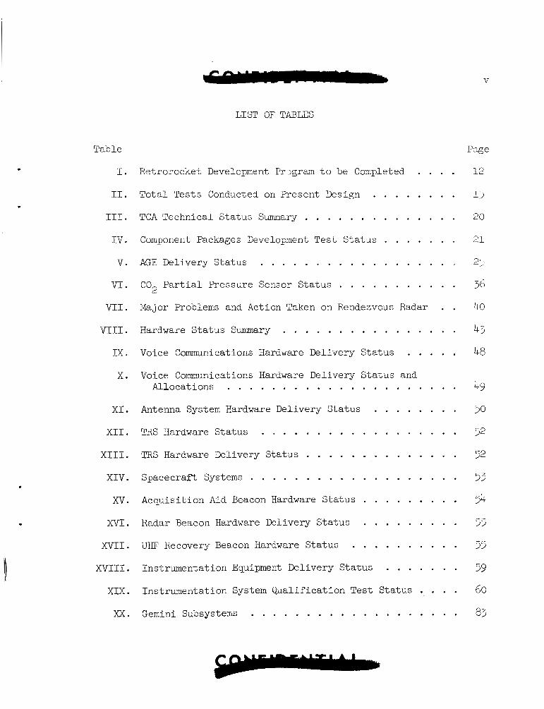
LIST OF TABLES
Table Page
I . Retrorocket Development Prlgram t o be Completed . . . . 1-2 I1 . Tota l Tests Conducted on Present Design . . . . . . . . 1)
I11 . TCA Technical S t a tus Summary . . . . . . . . . . . . . . 20 I V . Component Packages Development Test S t a t u s . . . . . . . 131
V . AGE Delivery S ta tus . . . . . . . . . . . . . . . . . . 2:1
VI . CO P a r t i a l Pressure Sensor S ta tus . . . . . . . . . . . 36 V I 1 . Major Problems and Action Taken on Rendezvous Radar . . 40
2
V I 1 1 . Hardware S ta tus Summary . . . . . . . . . . . . . . . . 45
IX . Voice Communications Hardware Delivery S ta tus . . . . . 48
X . Voice Communications Hardware Delivery S ta tus and . . . . . . . . . . . . . . . . . . . . . 49 Allocat ions
. . . . . . . . . X I Antenna System Hardware Delivery S ta tus 50
X I 1 . TRS Hardware S ta tus . . . . . . . . . . . . . . . . . . 52
X I 1 1 . TRS Hardware Delivery S ta tus . . . . . . . . . . . . . . 52
X I V . Spacecraft Systems . . . . . . . . . . . . . . . . . . . 53
XV . Acquisi t ion Aid Beacon Hardware S ta tus . . . . . . . . . 54
X V I . Radar Beacon Hardware Delivery S ta tus . . . . . . . . . 55
XVII . UHF Recovery Beacon Hardware S ta tus . . . . . . . . . . 55
X V I I I . Instrumentat ion Equipment Del ivery S ta tus . . . . . . . 59
X I X . Instrumentat ion System Q u a l i f i c a t i o n Test S t a tus . . . . 60
. . . . . . . . . . . . . . . . . . . . XX Gemini Subsystems 8;
1
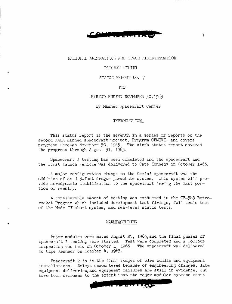
NATIOTIAL AERONAUTICS AID SPACZ
P R 3 G X : JEI I I I J I
STXKJS REPORT ITO. 7
. f o r
PERIOD ENDING NOVEMBEB 30,1963
By Manned Spacecraf t Center
INTRODUCTION
This s t a t u s r epor t is the seventh i n a s e r i e s of r e p o r t s on the
The s i x t h s t a t u s r epor t covered second NASA manned spacecraf t p ro j ec t , Program GEMINI, and covers progress through November 30, 1963. t he progress through August 31, 1963.
Spacecraf t 1 t e s t i n g has been completed and the spacecraf t and t h e f i r s t launch vehic le w a s de l ivered t o Cape Kennedy in October 1963.
A major configurat ion change t o t h e Gemini spacec ra f t was the a d d i t i o n of an 8.3-foot drogue parachute system. v ide aerodynamic s t a b i l i z a t i o n t o t h e spacecraf t du,ring t h e las t por- t ion of reent ry .
This system w i l l pro-
A considerable amount of t e s t i n g was conducted i n t h e TG385 Retro- rocket Program which included development tes t f i r i n g s , fu l l - sca le t e s t of t h e Mode I1 abor t system, and se-level s t a t i c t e s t s .
MANUFACTURING
Major modules were mated August 25, 1963,and t h e f i n a l phases of Test were completed and a r o l l o u t
The spacecraf t w a s de l ivered spacec ra f t 1 t e s t i n g were started. inspec t ion w a s held on October 1, 1963. t o Cape Kennedy on October 4, 1963.
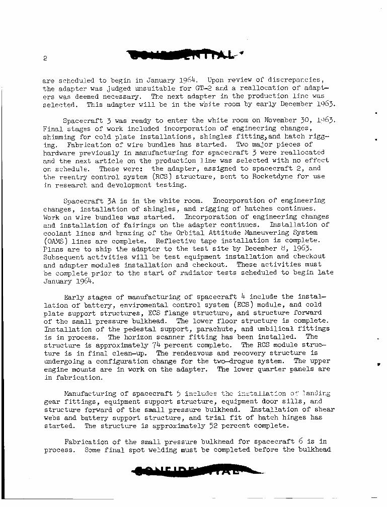
Spacecraft 2 is i n the f i n a l s t ages of wire bundle and equipment i n s t a l l a t i o n s . Delays encountered because of engineering changes, l a te equipment de l iver ies ,and equipment f a i l u r e s a r e s t i l l i n evidence, bu t have been overcome t o the ex ten t that t h e major modular systems t e s t s
2
a r e scheduled t o begin i n January 1964. Upon review of d i sc repanc ie s , t h e adapter w a s judged unsu i t ab le f o r GT-2 and a r e a l l o c a t i o n of a d a p b e r s was deemed necessary. The next adapter i n t h e product ion l i n e w a s s e l ec t ed . This adapter w i l l be i n t h e white room by e a r l y December lcl63.
Spacecraft 3 w a s ready t o e n t e r t h e white room on November 307 1.363. F i n a l s tages of work included incorpora t ion of engineering changes, shimming f o r co ld p l a t e i n s t a l l a t i o n s , sh ing le s f i t t i n g , and hatch rigg- ing. Fabr ica t ion of wire bundles has s t a r t e d . Two major p ieces of hardware previously i n manufacturing f o r spacec ra f t 3 were r e a l l o c a t e d and t h e next a r t i c l e on t h e production l i n e w a s s e l e c t e d wi th no e f f e c t on schedule. These were: t h e adap te r , ass igned t o spacec ra f t 2 , and t h e r een t ry c o n t r o l system (RCS) s t r u c t u r e , s e n t t o Rocketdyne for use i n research and development t e s t i n g .
Spacecraft 3 A is i n t h e white room. Incorporation of engineering changes, i n s t a l l a t i o n of sh ing le s , and r igg ing of hatches continues. Work on wire bundles w a s s t a r t e d . Incorporation of engineering changes and i n s t a l l a t i o n of f a i r i n g s on t h e adapter continues. I n s t a l l a t i o n of coolant l i n e s and brazing of t h e O r b i t a l A t t i t ude Maneuvering System ( O M ) l i n e s a r e complete. Ref lec t ive t ape i n s t a l l a t i o n is complete. P lans are t o s h i p t h e adapter t o t h e t es t s i t e by December U7 1963. Subsequent a c t i v i t i e s w i l l be t e s t equipment i n s t a l l a t i o n and checkout and adapter modules i n s t a l l a t i o n and checkout. These a c t i v i t i e s must be complete prioi- t o t h e s tar t of r a d i a t o r t e s t s scheduled t o begin l a t e January 1964.
Ear ly s t ages of manufacturing of spacec ra f t 4 include t h e in s t a l - l a t i o n of b a t t e r y , enviromental c o n t r o l system (ECS) module, and co ld p l a t e support s t r u c t u r e s , ECS f l ange s t r u c t u r e , and s t r u c t u r e forward of t h e s m a l l p r e s su re bulkhead. The lower floor s t r u c t u r e is complete. I n s t a l l a t i o n of t h e p e d e s t a l support , parachute, and umbi l ica l f i t t i n g s is i n process. The horizon scanner f i t t i n g has been i n s t a l l e d . The s t r u c t u r e is approximately 74 percen t complete. The RCS module s t ruc- t u r e i s i n f i n a l clean-up. The rendezvous and recovery s t r u c t u r e i s undergoing a conf igura t ion change f o r t h e two-drogue system. The upper engine mounts are i n work on t h e adapter . The lower qua r t e r pane ls a r e i n f a b r i c a t i o n .
Manufacturing of spacec ra f t 5 inc ludes t h e i n s t a l l a t i o n 07 landing gear f i t t i n g s , equipment support s t r u c t u r e , equipment door s i l ls , and s t r u c t u r e forward of t h e small p re s su re bulkhead. webs and b a t t e r y support s t r u c t u r e , and t r i a l f i t of hatch hinges has s t a r t e d . The s t r u c t u r e i s approximately 32 percent complete.
I n s t a l l a t i o n of shear
.
Fabr ica t ion of t h e small p re s su re bulkhead f o r spacec ra f t 6 is i n process. Some f i n a l spot welding must be completed before t h e bulkhead
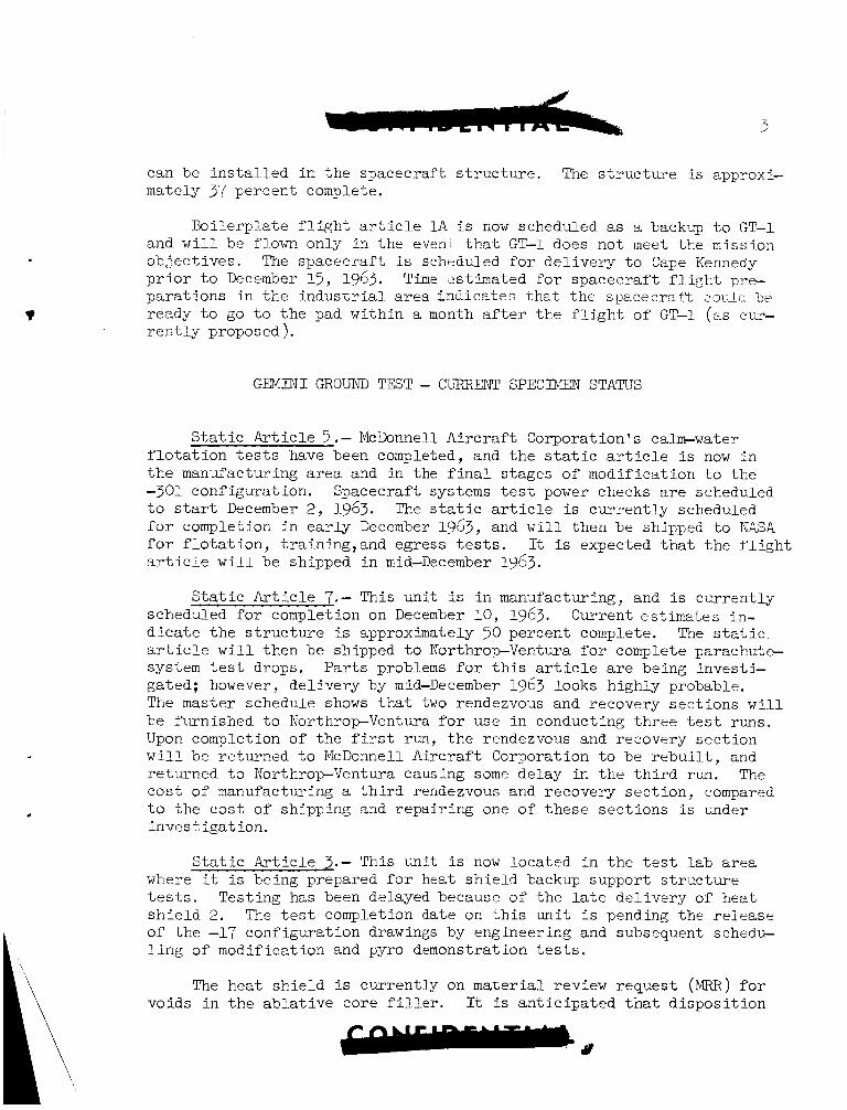
can be i n s t a l l e d i n t h e spacecraf t s t r u c t u r e . The s t r u c t u r e is approxi- mately 37 percent complete.
Bo i l e rp l a t e f l i g h t a r t i c l e 1 A i s now scheduled as a backup t o GT-1 and w i l l be flown only i n t h e evew t h a t GT-1 does not meet the mission ob jec t ives . The spacec ra f t is scheduled for d e l i v e r y t o Cape Kennedy p r i o r t o December 13, 1963. pa ra t ions i n t h e i n d u s t r i a l area Lndicates That t h e spacec ra f t i.ouLd be ready t o go t o t h e pad wi th in a month af ter t h e f l i g h t of GT-1 (as cur- r e n t l y prop o s ed ).
Time zst imated f o r spacec ra f t f l i g h t pre-
G E M I N I GROUND TEST - CURRENT SPECIMEN STATUS
S t a t i c A r t i c l e 5 .- Mcbnnel l A i r c r a f t Corporat ion 's calm-water f l o t a t i o n tes ts have been completed, and t h e s t a t i c a r t i c l e is now i n t h e manufacturing a r e a and i n the f i n a l s tages o f modif icat ion t o t h e -301 conf igura t ion . Spacecraf t systems t e s t power checks are scheduled t o start December 2, 1963. The s t a t i c a r t i c l e is c u r r e n t l y scheduled f o r completion i n early December 1963, and w i l l then be shipped t o NASA f o r f l o t a t i o n , t r a in ing , and egress tests. It is expected t h a t t h e f l i g h t a r t i c l e w i l l be shipped i n mid-December 1963.
S t a t i c A r t i c l e 7.- This u n i t is i n manufacturing, and is cu r ren t ly scheduled f o r completion on December 10, 1963. Current estimates in- d i c a t e t h e s t r u c t u r e is approximately 30 percent complete. The s t a t i c a r t i c l e w i l l then be shipped t o NorthropVentura f o r complete parachute- system t e s t drops. P a r t s problems f o r t h i s a r t i c l e are being invest i - gated; however, de l ive ry by mid-December 1963 looks highly probable. The master schedule shows t h a t two rendezvous and recovery sec t ions w i l l be furnished t o NorthropVentura f o r use i n conducting t h r e e t e s t runs. Upon completion of t h e f irst run, t h e rendezvous and recovery sec t ion w i l l be re turned t o McDonnell A i rc ra f t Corporation t o be r e b u i l t , and re turned t o NorthropVentura causing some delay i n t h e t h i r d run. The c o s t of manufacturing a t h i r d rendezvous and recovery sec t ion , compared t o t h e c o s t of shipping and r epa i r ing one of t h e s e sec t ions is under inves t iga t ion .
S t a t i c A r t i c l e 3.- This un i t i s now loca ted i n t h e t e s t l a b area where it is being prepared f o r heat s h i e l d backup support s t r u c t u r e t es t s . Test ing has been delayed because o f t h e l a te de l ive ry of heat s h i e l d 2. The t e s t completion date on t h i s u n i t i s pending t h e r e l e a s e of t h e -17 conf igura t ion drawings by engineer ing and subsequent schedu- l i n g of modif icat ion and pyro demonstration tes ts .
The hea t s h i e l d i s cu r ren t ly on material review reques t (MRR) for voids i n t h e a b l a t i v e core f i l l e r . It i s a n t i c i p a t e d t h a t d i s p o s i t i o n
4
w i l l be completed i n time f o r s h i e l d de l ive ry t o t h e t e s t l a b i n mid- December 1965.
S t a t i c A r t i c l e 4.- This u n i t i s now loca ted i n t h e t e s t lab whert cyc l ing and u l t ima te pressure t e s t s a r e now i n progress . cyc l ing phase of t h i s t e s t run , t h e left-hand hatch blew open. Inves- t i g a t i o n revealed t h a t i n t e r f e rence between a torque-box cover a t tach- b o l t and the crank assembly r e s t r i c t e d t h e over-center t r a v e l of t h e l a t c h mechanism. The t e s t w a s re-rwi under var ious t e s t se tups i n an e f f o r t t o repeat t h i s condi t ion. As a r e s u l t , it w a s proven t h a t t h e blown hatch r e s u l t e d from t h e in t e r f e rence condi t ion. It w a s a l s o found t h a t t h e degree of l a t c h engagement va r i ed wi th t h e speed a t which t h e l a t ch ing handle w a s c losed. Engineering w i l l add a po in te r t o t h e la tch- ing mechanism t o i n d i c a t e when it is f u l l y engaged.
During t h e
SPACECRAFT
?
Rework is now i n process t o remove in t e r f e rence and re - r ig t h e 1 e Y - L - hand hatch. It i s a n t i c i p a t e d t h a t t h e rework w i l l be completed by D e - cember 7, 1963.
The NorthropVentura parachute q u a l i f i c a t i o n tests on s t a t i c arti- c l e 4 w i l l be cancelled. S t a t i c a r t i c l e 4 w i l l be modified t o t h e -3 configurat ion and used f o r t h e f i n a l q u a l i f i c a t i o n tests of t h e high- a l t i t u d e drogue parachute configurat ion.
S t a t i c A r t i c l e 2.- This u n i t is i n t h e early s t ages of manufactur- ing. The ECS frame and lower f l o o r p o r t i o n are complete. Pos i t ion ing of t h e torque box on t h e s i l l s t r u c t u r e p r i o r t o welding is i n process .
Boi le rp la te 3A.- Bo i l e rp l a t e 3A is c u r r e n t l y scheduled for d e l i v e r y t o t h e test lab from manufacturing on December 10, 1963.
Delivery and Launch Schedule
A proposed de l ive ry schedule f o r t h e spacec ra f t and launch veh ic l e , and t h e Agena t a r g e t launch schedule are presented i n f i g u r e 1.
The following sec t ion conta ins information which d e l i n e a t e s t h e s t a t u s of the spacec ra f t and i t s systems.
CONFIGURATION AND WEIGHT
Configuration
A major conf igura t ion change t o t h e Gemini spacecraf t has been made during t h i s r epor t ing per iod which cons i s t ed of t h e add i t ion of an 8.3-foot drogue parachute system. I ts purpose w i l l be t o pi’ovide aerc- dynamic s t a b i l i z a t i o n of t h e spacec ra f t during t h e last po r t ion of re- en t ry ; namely from 50,000 f e e t t o 10,000 f ee t , i n s t ead of depending u p on t h e r e e n t r y c o n t r o l system as previous ly planned. This parachute system a l s o provides t h e time t o j e t t i s o n t h e r e e n t r y con t ro l system f u e l and ox id ize r without damaging any equipment.
Severa l minor conf igura t ion changes w e r e a l s o made. One of t h e s e changes increased t h e cockpi t a rea t o accommodate a 90-percent i le man on early spacec ra f t wi th t h e l a t e r spacec ra f t t o accommodate a 92-per- c e n t i l e man i n l i e u of t h e o r i g i n a l requirement f o r a 75-percent i le man. Another change incorporates a sealed adap te r compartment w i th con t ro l l ed vent ing during launch t o provide t h e des i r ed pressure d i f f e r e n t i a l .
Weight
During t h i s r epor t ing per iod, t h e fol lowing launch weight changes The 2-day rendezvous mission conf igura t ion space- have been recorded.
c r a f t weight, w i th parachute landing system, increased from 6,973 pounds t o 7,066 pounds, and t h e l h a y mission conf igura t ion spacec ra f t in- c reased from 6,766 t o 6,867 pounds. weight t r e n d of 30 t o 35 pounds per month increase noted i n t h e last r e p o r t i s s t i l l va l id . This t rend has now ex i s t ed f o r over n ine months. A s i n t h e previous per iods , most of t h e weight changes repor ted were very minor (p lus o r minus 1 t o 3 pounds) and tended t o cancel each o ther . The on ly major weight changes repor ted during t h i s per iod were i n t h e adapter . system and it r e s u l t e d from strengthening requi red as a r e s u l t of the previous ly repor ted abor t t e s t failuxe. It is anticipated,however, t h a t a d d i t i o n a l t es t s now scheduled may reduce t h i s increase by as much as 50 pounds. An increase of 12 pounds r e s u l t e d from replac ing t h e i n t e r n a l go ld p l a t i n g on t h e equipment s ec t ion of t h e adapter with aluminum f o i l because of cor ros ion caused by the p l a t ing . The b r i g h t i n t e r n a l su r f ace is requi red f o r thermal cont ro l . Addi t iona l work is being done t o f i n d a s u i t a b l e p l a t i n g technique. These e f f o r t s i n both areas may succeed i n reducing t h e weight increase f o r t h i s per iod by a t least one-half which w i l l improve t h e cur ren t t rend considerably.
These increases confirm t h a t t h e
An increase of 60 pounds was made i n t h e re t rograde rocke t
6
STRUCTURE
During t h i s qua r t e r , launch loads were app l i ed t o t e s t a r t i c l e s a t both Mar t in Company and McDonnell A i r c r a f t Corporation. &so, t h e space- c r a f t v ib ra t ion survey w a s completed; and design improvements were i n i - t i a t e d on the hatch mechanism and drogue parachute incorporation. Pro- blems have a r i s e n and t h e reso lv ing a c t i o n has been i n i t i a t e d about retrobeam over-heating a t h i g h - a l t i t u d e a b o r t , p rope l l an t boos te r dome rup tu re a t h i g h l t i t u d e a b o r t , t h e s t a t i c test-to-failure a t Martin Company, M a r t i n Company's buf'fet t es t results, and beryl l ium sh ing le manufacture.
In t e r f ace t e s t s . - Martin Company appl ied t h e u l t ima te t e n s i l e and u l t ima te compressive launch loadings t o t h e i r t e s t specimen i n t h e l a t t e r p a r t of Ju ly 1963. sonic b u f f e t wi th i n t e r n a l compartment pressure , which g ives an equiva- l e n t load a t t h e "spacecraft-launch veh ic l e" i n t e r f a c e of 110,000-pound t ens ion and 77,600-pound compression; and (2) t r anson ic b u f f e t without p re s su re , which g ives a n equiva len t load of 67,500~pound t ens ion and 120,>00-pound compression. burnout were appl ied , maintained, and then a simulated aerodynamic hea t pu l se applied. d i z e r tank s t r u c t u r e and t h e McDonnell A i r c r a f t Corporation spacec ra f t - adapter s t r u c t u r e withstood t h e loads s a t i s f a c t o r i l y .
These two c r i t i c a l loadings a re : (1) t h e i r t ran-
The u l t ima te condi t ions a t second s t age
Both t h e Martin Company's forward s k i r t and upper oxi-
The t e s t specimen a t Mar t in Company had a forward boos ter s k i r t t h a t d i d not meet production s tandards , and , therefore , it w a s ins t ru- mented w i t h only enough s t r a i n gages (about twenty) t o monitor t h e tes t . A g r e a t dea l of concern has been expressed about t h e i n t e r f a c e s t r e s s d i s t r i b u t i o n between t h e skin-s t r inger adapter and t h e Gemini Launch Vehicle semi-rnonocoque forward s k i r t . This concern, about t h e e f f e c t s of poss ib l e f u t u r e design changes subsequent t o t h e s t a t i c tests, moti- vated Mar t in Company t o i n i t i a t e a fol low-on test . w a s replaced wi th one t h a t met boos te r production s tandards and t h e i n t e r f a c e a rea w a s instrumented with some 400 s t r a i n gages, 90 percent of t h e s e on t h e compression s i d e and t h e remainder on t h e t ens ion s i d e . The t e s t was t o proceed t o f a i l u r e . t h e t e s t was t o be conducted, it w a s discovered t h a t t h e spacecraf t - adapter lower-interface attachment r i n g contained excessive r i v e t i n g , which made it nonrepresentat ive of product ion adapter s t r u c t u r e . The tes t w a s not allowed t o proceed and a meeting was he ld a t Aerospace Corporation on November 13, 1963, between NASA, A i r Force Space Systems Division, Aerospace Corporation, McDonnell A i r c r a f t corpora t ion , and Martin Company t o decide t h e course of a c t i o n . It w a s decided t o per- form t h e t ransonic b u f f e t u l t ima te compressive condi t ion on t h e tes t specimen i n t h e "as is" condi t ion. Then t h e excess r i v e t s w i l l be re-
The forward s k i r t
P r i o r t o November 5, 1963, t h e d a t e
7
moved and inspected moval, t h e u l t ima te
by t h e spacecraf t con t r ac to r . Following r i v e t re- compressive condi t ion w i l l be r e -app l i ed , then t h e
u l t ima te t ens ion condi t ion applied. F i n a l l y , t h e u l t ima te compressive loading w i l l be appl ied , then a puze bending moment appl ied u n t i l f a i l - u re occurs.
J
Buffet t e s t s . - During t h e f i r s t week of September 1963, t h e M a r t i n Company conducted b u f f e t model t e s t s a t Ames Research Center. They u t i l i z e d an i n e r t i a l compensated balance technique which is s a i d t o produce t h e moment due t o bu f fe t as a d i r e c t measurement. This i s a new technique which d i d not meet w i th t h e approval of t h e Manned Space- c r a f t Cen te r ' s S t r u c t u r e s and b h t e r i a l s Branch of t h e S t ruc tu res and Mechanics Division a t t h e time o f t h e t e s t . The t e s t w a s run between Mach 0.6 and Mach 1.14. The buffe t loading w a s expected t o peak and diminish i n t h i s region, but it was s t i l l increas ing a t a steady r a t e when t h e l i m i t i n g Mach 1 .14 flow w a s reached. Company recommended a follow-on b u f f e t t e s t i n a higher Mach flow.
Consequently, Mar t in
On November 22, 1963, Martin Company and Aerospace Corporation r e p r e s e n t a t i v e s b r i e f e d t h e MSC S t r u c t u r e s personnel on t h e i r b u f f e t measurement technique and t h e r e s u l t s of t h e f i rs t test . t h a t by t h e f i rs t week of December 1963, t h e S t r u c t u r e s and Mater ia l Branch of t h e S t ruc tu res and Mechanics Division w i l l recommend t h e f o l l o w 4 n b u f f e t t e s t t o t h e Gemini Program Office (GPO), and Martin Company w i l l submit t h e c o s t and schedule e s t ima te of t h e t e s t .
It is expected
McDonnell A i r c r a f t Corporation subjec ted s t a t i c a r t i c l e 3 t o l i m i t - launch loads October 31, 1963, and u l t ima te launch loads t h e fol lowing day. The u l t ima te equiva len t load w a s 138,50(Lpound compression and 49,700-pomd tension. The s t r u c t u r e withstood t h e load s a t i s f a c t o r i l y . The adapter sk in on t h e compression s i d e buckled l o c a l l y , as expected, i n sus t a in ing t h e u l t ima te load; however, most of t h e buckle disappeared when t h e load w a s r e l i eved .
On August 16, 1963, McDonnell A i r c r a f t Corporation subjec ted t h e spacec ra f t nose f a i r i n g t o l 2 . 5 p s i p re s su re over t h e sur face of t h e f a i r i n g , which is 136 percent of design l i m i t load. The f a i r i n g w i t k - s tood t h e loading s a t i s f a c t o r i l y , d e f l e c t i n g only 0.058 inch maximum under t h e load.
The v i b r a t i o n survey on s t a t i c a r t i c l e 4 w a s completed September 10, 1963. ment where t h e heavy hatches were rep laced wi th l i g h t hatches and o t h e r rework accomplished during t h e period of September 15 through November 2 , 1963. The s t a t i c a r t i c l e i s now i n t h e i n i t i a l phases of i t s cabin- p re s su re cyc l ing t e s t s . The v ib ra t ion survey uncovered some problem a r e a s about t h e pulse code modulation programer, r e e n t r y c o n t r o l system
The s t a t i c a r t i c l e was then s e n t t o t h e Manufacturing Depart+
a
valve package I'B", t ape recorder , and small pressure bulkhead. These a reas a r e being inves t iga ted f o r improved mounting from a v ib ra t ion s tandpoint . i n t h i s inves t iga t ion .
Relays mounted on t h e s m a l l p ressure bulkhead a r e included
A n improvement i n t h e hatch mechanism t o reduce opening and c los ing loads is i n design. Segment and pinion gear ing is being employed t o re- duce ex terna l opening and c los ing loads t o 25 pounds and 30 pounds, re- spec t ive ly , a t each end of a "T" handle with an e f f e c t i v e 7-inch rad ius . The in s ide handle operat ing loads a r e t h e same, 25 pounds t o open and 30 pounds t o c lose , a c t i n g as a s i n g l e load on an e f f e c t i v e 11-inch radius .
Approval was given and design i n i t i a t e d t o incorporate a drogue parachute in t h e recovery system. S t r u c t u r a l l y , t h i s change w i l l in- volve only t h e t i p of t h e rendezvous and recovery sec t ion (approximately nine inches of s t r u c t u r e below t h e radar ground plane) . conceived such t h a t t h e loading on t h e r e e n t r y c o n t r o l system sec t ion ad jacent t o t h e rendezvous and recovery s e c t i o n does not exceed t h e pre- s e n t design load, even f o r a r o t a t i n g spacecraf t . A r eo r i en ted f l i g h t t e s t program w i l l be used t o qua l i fy t h i s design. It is planned t o pro- ceed with a rendezvous and recovery sect ion-reentry c o n t r o l system sec- t i o n s t a t i c t e s t , using t h e e x i s t i n g s t r u c t u r e s , and perform l o c a l tests on t h e redesigned rendezvous and recovery sec t ion l a t e r .
The design is
me second fu:l-scale Arnold Engineering Development Center (AEDC) h igh -a l t i t ude abor t t e s t r e s u l t e d i n overheat ing t h e r e t ro rocke t support beams such t h a t they f a i l e d immediately p r i o r t o t h e rocke ts ceasing f i r i n g . The over-heating w a s a t t r i b u t e d t o t h e c lose proximity of t e s t chamber w a l l s which were not r ep resen ta t ive of a c t u a l f l i g h t condi t ions a t 70,000-foot a l t i t u d e . a hea t ing inves t iga t ion a t higher a l t i t u d e s , where t h e rocke t plumes i n t e r s e c t t o such an ex ten t as t o t r a p flow i n t h e cen te r and reverse it toward the beam s t r u c t u r e . NASA, Mcbnne l l A i r c r a f t Corporation, and ARO met a t t h e AEDC on November 7 , 1963, t o determine if a t h r u s t i n g model test w a s t e c h n i c a l l y f e a s i b l e i n any of AEDC's f a c i l i t i e s . It was determined t h a t t h e J-2A c e l l would permit a s a t i s f a c t o r y t e s t , bu t it is t i e d up wi th T i t an I11 and Apollo p r o j e c t s u n t i l June 1965. The GPO is cur ren t ly negot ia t ing wi th t h e A i r Force Space Systems Division f o r a few weeks of J-2A c e l l t e s t i n g time during t h e month of February 1964. model design and t e s t d e f i n i t i o n .
However, t h e inc ident d i d po in t ou t a need f o r
Mcbnnel l A i r c r a f t Corporation has been d i r e c t e d t o proceed with
M a r t i n Company re leased a repor t , LV-211, during t h e previous re- por t ing period ind ica t ing t h a t if t h r u s t i s terminated between 40 and lo5 seconds a f t e r launch, t h e boos te r ' s remaining p rope l l an t s w i l l r u p t u r e t h e upper tank domes due t o drag dece le ra t ion of t h e vehicle . of course, implies we have a problem i n t h e early Mode I1 abor t region,
This,
3
(70,000-foot a l t i t u d e occuring at about 93 seconds) where t h e normal procedure i s t o terminate t h r u s t p r i o r t o r e t ro rocke t salvo. The anal- y s i s i s admit tedly over ly conservative; however, very l i t t l e i s known regarding more r e f ined a n a l y t i c a l techniques f o r determining t h e loading. Therefore, a t t h e last Abort Panel meeting on October 22, 1963, it w a s decided t h a t Langley Research Center w i l l perform model t e s t s , producing f l u i d impact da t a from which a more r e a l i s t i c s t r u c t u r a l a n a l y s i s can be made.
A review w a s held with McDonne11 Ai rc ra f t Corporation on November 5 , 1963, concerning t h e beryll ium sh ingles f o r t h e r e e n t r y c o n t r o l sys- tern and rendezvous and recovery s t ruc tu res . Because of a s t r i k e e a r l y i n t h e year as we l l as o t h e r manufacturing d i f f i c u l t i e s , sh ingle t e s t s have been delayed. w8.s rescheduled t o be conducted two months e a r l i e r by in t eg ra t ing it wi th another t e s t . The cross-rolled beryll ium, used f o r Gemini, has presented a number of manufacturing problems i n a t tempting t o avoid c raz ing , f l ak ing , poros i ty , lamination, and cracking f l a w s i n t h e f in i sh - ed sh ingles . A meeting w a s he ld a t Pioneer Astro Indus t r i e s , Chicago, I l l i n o i s , on November 14 , 1963, where it w a s decided t h a t Ba te l l e Mem- o r i a l I n s t i t u t e would analyze these problems, and Pioneer Astro would use more chemical e tching i n t h e machining opera t ion and l i g h t e r c u t s where machine t o o l s could not be avoided.
An important t e s t , t h e docking impact load a t -100' F,
Mater ia ls and Test ing
The quest ionable a reas t h a t appeared during t h e q u a l i f i c a t i o n t e s t - ing of t h e prototype heat s h i e l d have been rescheduled t o be performed on t h e s t a t i c a r t i c l e 3 s h i e l d a f t e r completion of t h e o the r tests. These tests w i l l be performed during t h e next r epor t ing per iod.
The process s tandard t h a t covers f a b r i c a t i o n and q u a l i t y acceptance t e s t i n g f o r t h e hea t s h i e l d has been r ewr i t t en during t h i s per iod. major change t o t h e document w a s t h e add i t ion of an acceptance t e s t i n g procedure f o r t he ab la t ion mater ia l .
The
k n u f ac t UT ing
The hea t s h i e l d has been de l ivered and accepted f o r spacec ra f t 1. The hea t s h i e l d i s d e f i c i e n t s ince it contains some uncured a b l a t i o n mater ia l ; however, it i s considered s u i t a b l e f o r t h e mission of space- c r a f t 1. The heat s h i e l d has been f ab r i ca t ed f o r spacec ra f t 2 and w a s scranped becailse of unacceptable s t r e n g t h of t h e backup s t r u c t u r e . Correct ive a c t i o n has been taken which includes rework of the vacuum
10
system and a r ev i s ion t o t h e process s tandard. f o r t he second s t a t i c a r t i c l e 3 hea t s h i e l d w a s not homogeneous and re- quired excessive curing time. The inves t iga t ion is cont inuing, bu t it appears t h a t t h e c a t a l y s t is impure. This def ic iency w i l l not be l i m i t - ing i n t h e use of t he second s t a t i c a r t i c l e 3 heat s h i e l d , s ince t h e s t r eng th i s not degraded.
The a b l a t i o n material
SOLD PROPELLANT ROCKET SYSTEM
Summary
TE-385 Retrorocket Program- Two development t e s t f i r i n g s were con- ducted during t h i s r epor t ing period. The primary e f f o r t on the retro- rocke ts has been placed upon v e r i f i c a t i o n of t he redesigned nozzle as- sembly. To t h i s end, t h r e e s t a t i c sea- leve l t e s t s were success fu l ly conducted.
Retrorocket Abort Test Program.- A second fu l l - sca le t es t of t h e Mode I1 Abort System w a s conducted ahead of schedule a t AEDC on October 4, 1963. of t h e redesigned r e t ro rocke t nozzle assembly i n i ts opera t ing environ- ment. Since t h e motors performed without a malfunction under t es t con- d i t i o n s t h a t were more severe than is a n t i c i p a t e d i n f l i g h t , t he motor t e s t w a s considered an 1mq'xiLified success . However, as a r e s u l t of considerable hea t ing from the exhaust gases p lus t h e rocke t t h r u s t on t h e beams, t h e s t r u c t u r e f a i l e d a f t e r s l i g h t l y more than 4 seconds of a ?.>second burn t i m e . Correct ive measures t o be taken as a r e s u l t of t h e retrobeam f a i l u r e w i l l be repor ted i n t h e s t r u c t u r a l s ec t ion of t h i s r epor t .
The purpose of t h e t e s t was t o v e r i f y t h e s t r u c t u r a l i n t e g r i t y
TE-385 Retrograde Rocket
Schedule.- As a r e s u l t of t h e successfu l a b o r t t e s t of t h e motors a t AEDC, the schedule is now expected t o be more accura te . Twelve re- search and development t e s t s remain t o be completed on t h e r e t ro rocke t s . Motor development t e s t i n g is now scheduled f o r completion by midJanuary 1964. 1964,and extend over a twelve-week per iod r a t h e r than four weeks as ear- l i e r reported. This a d d i t i o n a l time has been requested by Thiokol Chem- i c a l Corporation as a r e s u l t of a change i n temperature cyc l ing require- ments by McDonnell A i r c r a f t Corporation, and a requirement f o r t h e use of spacecraf t motor mounts during t h e s t a t i c q u a l i f i c a t i o n t e s t f i r i n g s .
Motor q u a l i f i c a t i o n t e s t i n g is scheduled t o begin during mid-March
I n i t i a t o r q u a l i f i c a t i o n has been success fu l ly completed and pyrogen Py;ogen qual- q u a l i f i c a t i o n i n i t i a t e d on schedule i n mid-November 1963.
if i c a t i o n should be complete by midJanua ry 1964.
Retrorocket de l ive ry f o r spacecraf t 2 has been delayed u n t i l mid- March lg64qat which time the motors f o r spacec ra f t 3 w i l l a l s o be de- l i v e r e d . t h e r equ i r ed d a t e f o r motor i n s t a l l a t i o n i n t o spacec ra f t 2. A s e t of 4 motors wi th i n e r t p rope l l an t has been de l ive red for spacec ra f t 3A.
The March 1964 de l ivery is w e l l i n advance (about 7 weeks) of
. Design.- The redesigned nozzle assembly has been shown t o be s t r u c t c
u a l l y sound i n t h r e e successfu l s e a - l e v e l s t a t i c t e s t s , one of which in- cluded a s t a t i c s ide- load t e s t o f t h e nozzle as w e l l as a fu l l - sca l e a l t i t u d e a b o r t t e s t a t AEDC. No o t h e r design changes have been incor- porated.
Tests . - A d i scuss ion of a l l t e s t i n g on t h e r e t ro rocke t s is con- -- t a i n e d i n t h e following paragraphs:
a. Development t e s t s , Seven developmental-test motor f i r i n g s were conducted during t h i s period. O f t h e s e seven t e s t f i r i n g s , only two f i r i n g s were tests planned i n the o r i g i n a l development program. One motor w a s f i r e d t o provide a batch check on eleven motors c a s t f o r two a b o r t t e s t s a t AEDC and t h e remaining f o u r motors were f i r e d i n t h e second tes t .
In addi t ion .seven o the r inotors were c a s t f o r a t h i r d fu l l - s ca l e t e s t a t AEDC ( re t rograde t e s t ) which allowed 3 spares f o r t h e l a s t two
t e s t s . Two o f these motors vi11 ha--e d r a i n s exposed t o 5 x lo-" mm IIg vacuum r o r 1 4 days t o determine t h e e f f e c t s on i g n i t i o n and burning of "space ag ing ." Four o t h e r motors w i l l be tested t o t h e r ev i sed thermal cyc le environmental t e s t s which r e s u l t e d from more r ecen t thermal con- s i d e r a t ions by McDonnell A i rc ra f t Corporation. k s i c a l l y , t h e number of cyc les has been increased and t h e temperature l i m i t s have been de- creased. No t e s t p lans e x i s t for t h e seventh motor.
/
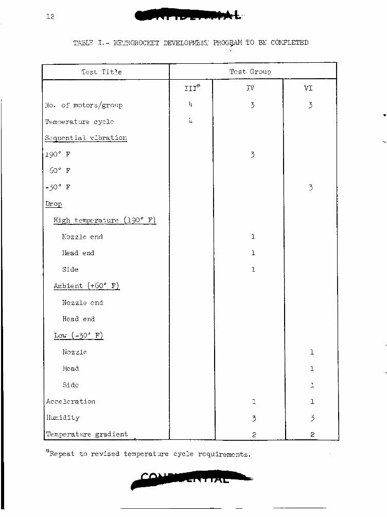
Exclusive of t h e above t e s t i n g , t h e remaining research and d e v e l o p ment t e s t s t o be conducted cons i s t of three s t a t i c t e s t s i n Group V and t h r e e i n Group V I . Table 1 presen t s t h e sequence of environments. The motors f i r e d i n support of t h e nozzle redes ign v e r i f i c a t i o n tests re- ceived t h e complete environment exposure r equ i r ed by Group V and were success fu l ly t e s t e d . 2,400 pocmds placed upon t h e e x i t cone a f t e r t h e motor had been f i r e d . F a i l u r e occurred wi th in t h e center of t h e p l a s t i c cone and not ad jacen t t o t h e metal bulkhead. p l a s t i c i n t e r f a c e a f t e r sectioning.
The batch check motor had s t a t i c s i d e loads of
No cracks were observed i n t h e nozzle metal/
b. Q u a l i f i c a t i o n t e s t s .
1. Pressure c a r t r i d g e - Test ing is complete wi th no Yaiiures reported. However, McDonnell A i r c r a f t Corporation has not
12
TABLE 1.- ~ T R O R O C K E T DEVELOPMENT P R O G P TO BE COMPLETED
Test T i t l e
IO. of motors,/group
'emperature cycle
kquent i a l v ib ra t ion
-90" F
60" F
-30" F
?E%
High temperature (190" F)
Nozzle end
Head end
Side
Ambient (+GO" F) - Nozzle end
Head end
Low (-30" F) - - Nozzle
He ad
Side
2c ce l e r a t ion
h n i d i t y
Femperat w e gradien t
Test Group
IIP
4
4
IV
3
3
1
1
1
1
3
2
Repeat t o rev ised temperature cycle requirements. 45
V I
3
3
1
1
1
1
3
2

reviewed t h e t e s t repor t and thus does not consider t h e u n i t s qua l i f i ed .
2. Pyrogen - Test ing has commenced on t h e 50 u n i t s t o be qual- i f i e d and is on schediile wi th v i b r a t i o n t e s t i n g a l r eady com- p l e t e . Completion of t h i s program should occm- i n nid-Jan- uary 1964.
Retrorocket Abort T e s t Program
Test R u n No. 1. The t e s t discussed i n t h e previous s t a t u s r e p o r t has been documented by AEDC i n Reference A.
T e s t R u n No. 2. The ob jec t ive of t h i s t e s t w a s p r imar i ly t o v e r i f y t h e redesigned nozzle assembly of t h e TF&383 re t ro rocke t s . To t h i s end, f u l l du ra t ion engines and l ightweight I-beams were employed on a boi le r - p l a t e adapter and t e s t r i g , thereby dup l i ca t ing t e s t no. 1. T e s t con- d i t i o n s of t h e f i rs t run were dupl ica ted as c l o s e l y as poss ib le . Al- though a l l 4 motors performed properly with no evidence of cracking when sec t ioned i n t o halves , t h e I-beam d i d f a i l because of temperatures high- er than had been a n t i c i p a t e d p r i o r t o t h e t e s t . Correct ive measures t o be taken as a r e s u l t w i l l be repor ted i n t h e s t r u c t u r a l s ec t ion of t h i s r e p o r t .
Since t h e h igh temperatures encountered i n t h i s t e s t are bel ieved u n r e a l i s t i c compared t o a c t u a l f l i g h t condi t ions and r e s u l t e d from in te r - fe rence effects wi th t h e tunnel , t h e r e t rog rade t es t has been cancel led. Heating during t h e retromode is t o be obtained i n s c a l e model tests which w i l l a l s o be employed t o determine hea t ing e f f e c t s during t h e Mode I1 abor t .
LIQUID PROPELLANT ROCKET SYSTEMS
Schedules
The program milestone schedules are s t i l l being delayed as a r e s u l t of hardware u n a v a i l a b i l i t y and t h r u s t chamber assembly (TCA) development problems. The s t a t u s of production hardware d e l i v e r i e s , the research and development program and t h e q u a l i f i c a t i o n program is discussed s e p arately.
Reentry Control System Production Hardware Del iver ies . - With t h e except ion of t h e TCA's and explosive ca r t r idges , a l l components f o r t h e RCS on spacecraf t 2 have been de l ivered , Shipment of t h e remaining items should be complete by midJanuary 1964. Approximately 1-5 percerlt
14
of the hardware for spacec ra f t 3 has been del ivered; t he remainder of which should be de l ivered by February 1964.
OAMS Production Hardware Delivery. - The compat ib i l i ty tes t u n i t (CTU)-is considered s u f f i c i e n t l y complete t o f u l f i l l CTU tes t ob jec t ives , although a complement of TCA's w a s not de l ivered . The plan is t o update t h e CTU with a complete set of production TCA's as they become a v a i l a b l e on a non-interference b a s i s wi th q u a l i f i c a t i o n and f l i g h t hardware re- quirements. For spacec ra f t 2, a l l hardware has been de l ivered except TCA's and explosive ca r t r idges which should be shipped by e a r l y February 1964. Spacecraf t 3 hardware d e l i v e r i e s are about 10 percent complete. The remainder should be completed by March 1964.
Research and Development Components. - It is apparent from a re- cent i nves t iga t ion of t e s t s conducted a t Rocketdyne t h a t t h e research and development phase w i l l extend we l l i n t o 1964. Rocketdyne special- ists genera l ly a t t r i b u t e d most of t h e i r delays t o a lack of t e s t hard- ware, r a t h e r than development problems. One notab le exception i s t h e t h r u s t chamber development e f f o r t which remains we l l behind o the r c o w ponents due t o tec'hnical problems as w e l l as a l ack of hardware. Pre- d i c t i o n of a completion da te is d i f f i c u l t because of t h e hardware avai l - a b i l i t y unce r t a in t i e s and because a d e f i n i t e method of reso lv ing t h e o r b i t a t t i t u d e maneuvering system (OAMS) TCA l i f e problem has not been se l ec t ed .
Systems Testing. - No system t e s t i n g w a s conducted during t h i s re- por t ing per iod and on.ly very minor t e s t i n g has been conducted s i n c e e a r l y i n 1963. Again, t h e reason i s hardware unava i l ab i l i t y . Completion of the research and development system t e s t program is expected during the second qua r t e r of 1964, unless hardware continues t o remain unavail- ab l e , or other major development problems arise.
Qual i f ica t ion Test ing. - A s a consequence of t h e research and de- velopment programs' delays, t h e q u a l i f i c a t i o n program has experienced ser ious delays. Ij, order t o complete q u a l i f i c a t i o n t e s t i n g i n adequate time f o r support of a manned launch i n 1964, it may be necessary t o in- i t i a t e q u a l i f i c a t i o n t e s t i n g p r i o r t o completion of t h e development pro- gram. Because t h e program has been so adverse ly a f f e c t e d by a l ack of hardware, manufacturing has been rece iv ing major a t t e n t i o n . According t o t h e Rocketdyne program schedules, which i n t h e p a s t have been accu ra t e i n showing s l ippages , it now appears t h a t t h e q u a l i f i c a t i o n program is f i rmer due t o improved a v a i l a b i l i t y of t h e requi red hardware. Also, Rocketdyne has requested t h a t McDonnell A i r c r a f t Corporation supply a r e l a t i v e p r i o r i t y r a t i n g of components f o r t h e var ious spacec ra f t de- l i v e r i e s and f o r d i f f e r e n t types of t e s t s .
? ?
$ 3 3 :
n l n N c u
3 3 r n m
N W rl
c - x d (u 4 rl
cc m m m m m r - m d d r l d ri d r l d
Q d
16 cn cn V Q v1
N N +
o v v Q a J Q m m m
w w o rl mt- N N
' 0
B
5 4
k + 4 a rl 4
cr
m
rl
4
s O .
k ' a, 'Q
C .rl
4 0
n c .A m 0 rl a w :: i2
0 v3
N M N
no no no no In0 no no no no no n N N N N N N N I N N ( U N N N N N N N N N N N
17
ID c, rl
m aJ P;
aJ aJ0
0.P c v O L d o m
0 a
4 0 rl n 4 rl
In a3 o\ d N
F ? d 2 d d N
rl n rl
18
c d + k a a, +J
%
$ c, m
N w d
co N w w -s 8 8 co
f (u
n rl M (u
W M
K\ W
d A c-t
.
111
rl M a, 3 +)
2
E E b
n
+
4
a rl d $! o .d
'?
a, s + 9
k! .A d k r l
ai: SUI
3 0 a +
3 0 0 f P- t- 0 C O O M N N
d i n N N 3 n
4) f N
'? N r- a3 a3 N i a N ri
'? '? c o c o co a3 N cu
rl N
N. a d
CO M f M rl 3
D M 0 M M M M "i M m n
M M w w w w w w w w w I I r- W w
a3 rl M I -I I I 1
I I 0 rl d h L A A r d - 3 h l r y c u r \ r l r l d N N
I d & a 3 & & & A A & d , d d
20
v) t- N
d k In f
M N N 8 2 I4
c,
E a P 3
ln
f a Cn r-
m V a
2 s In N
d d c, E 8 W ri
V A
R
2 d m
J
B
m W c,
E: 4
21
I -
TABTZ IV. - COMPONENT PACKAGES D.EVELOPMETJT TEST STATUS
PACE2iGE
'A"
a.
b.
C.
d.
e.
f.
'B"
a.
b.
c .
d.
e.
f .
g .
h.
Forging
Manual valve
Pre s sure t ransducer
F i l t e r
Cartr idge valve
Assembly
Machined body
Manual valves
Pre s sure t ransducer
Check valves
Relief valves
Burst diaphrag
F i l t e r
Assembly
omple t e
X
X
X
X
X
X
X
X
X
X
X
Almost Complete
X
X
P a r t i a l l y C omple t e
X
No t e s t s ( o r unsucce ss ful)
b
22
TABLE IV.- COYPONEHT PACKAGES DEVELOPMENT TEST STATUS - Continued
PACKAGE
~~~
'C" and "D"
a.
b.
C .
d.
e.
'E "
a.
b.
C.
d.
e .
f .
g.
Machined body
Manual valve
F i l t e r
Cartridge valve
Assembly
Normally-ope n ca r t r idge valve
Normally- closed ca r t r idge valve
Pre s sure switch
Solenoid valve
F i l t e r
Manual valve
A s s emb 1 y
omp l e t e Almo s t Complete
X
STATUS
P a r t i a l l y Complete
X
x
X
No t e s t s ( o r uns ucce s s TU )
X
L
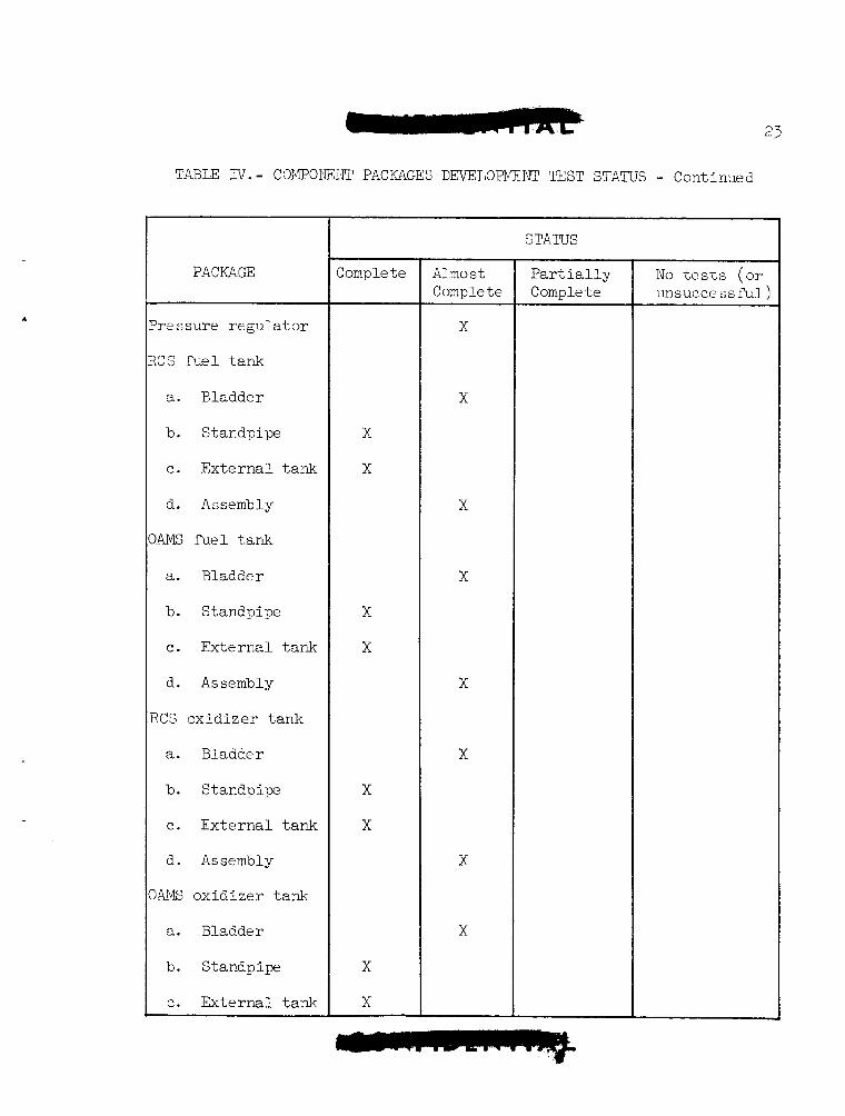
TABLE IV.- COWOI\EiSr PACKAGES DEVELOPMENT TEST STATUS - Continued
PACKAGE
're s sure r egu la to r
CS f u e l tank
a. Bladder
b. Standpipe
c. Ex te rna l tank
d. Assembly
).W fuel t ank
a. Bladder
b. Standpipe
c. Externa l tank
d. Assembly
ICs ox id ize r tank
a. Bladder
b. S t a n d p i p
e . Externa l tank
d. Assembly
)4MS ox id ize r tank
a. Bladder
b. Standpipe
e . Exte rna l tank
2omple te Almo s t Complete
X
X
X
X
X
X
X
X
STATUS ~ ~~
Par t i a 1 1 y ComDle te
N o t es t s ( o r unsuccessr'ul )
24 c- TEiBLT IV. - COJPOI\sENT PACKAGES DEVELOPMENT TEST STATUS - Cone! .I.?:?
PACKAGE Complete
d. Assembly
vlotor valves
Pre s s me - tempera t irid i c a t or
Braze fittings
RCS and OAMS Prcssurant tank
Cartridge valve s C and D
A
E (normally open)
Almo s t Complete
STATLTS ~
P a r t i a l l y Complete
X
No tes t s (or unsucce ss Tu1 )
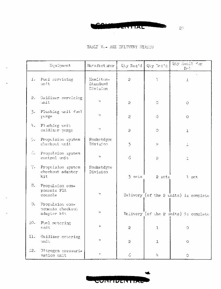
TABLE V.- AGE DELIVERY STATUS
E quiprne n t
1. Fbel se rv ic ing un it
2. Oxidizer s e rv i c ing u n i t
3. Flushing u n i t fuel Purge
4. Flushing u n i t ox id i ze r purge
5. Propulsion system c k ckout mit
6. Propulsion system c o n t r o l u n i t
7. Propulsion system che c kout adap te r k i t
8. Propulsion com- pDnents PIA console
9. Propulsior, com- ponents checkout adap te r k i t
10. Fuel metering u n i t
11. Oxidizer metering u n i t
12. Nitrogen ? r e s s u i - za t ion u n i t
Flanu f a c t mer
kmilt on- Standard Division
1 1
11
11
Rocke tdyne Div i s i nn
11
Rocket dyne Divi s i on
11
I 1
I 1
11
11
Q t y Req'd
e t s
D: 1 iver y
Delivery
Q t y Del'd Q t y Avail 'or De 1
( o f t h e 2 1 i i t s ) i s complete
0
0
0
26
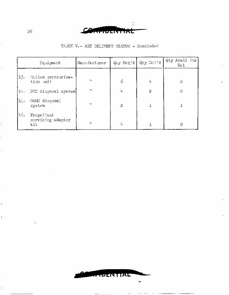
TA3LE V. - AGE DELIVERY STATUS - Concluded
E q u i pme n t
13. I k l i u m p re s swiza - t i o n u n i t
14 . RCS disposa l systen
lj. OAIG d i sposa l system
IC. Propel lant se rv ic ing adapter k i t
Manu r'ac t w e r Qty Req'd Q t y Avail i'or De 1
Des igri
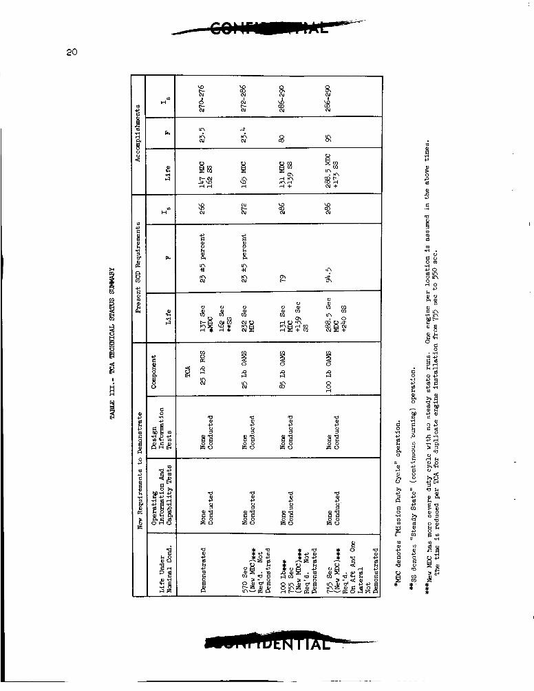
Thrust Chamber Assemblies. - A re-evaluation of t he 0AT.E duty c y c l e s by TkDonnell A i r c r a f t Corporation has r e s u l t e d i n an increascd l i f e requirement for a l l OAMS TCA's. This has compounded t h e TCA pro - lem s ince t h e p re sen t duty cycle requirements have no t Seen deinonsii-ated x ~ C i ~ i ^ spec i f i c a t i o n condi t ions on t h e 25+pound and l0CLpound TCA' s .
To meet t h e new requirements on t h e 100-pound TCA, Rocketdyne i s lowering e f f i c i ency from 92-94 percent t o 8-7 percent . The l i i 'e oi' bile @-pound TCA i s t o be bro-ught up t o t h e l0Gpound TCA l i m i t by dup l i ca t ing t h e chamber segment of t h e 100-pound TCA. Plans f o r t h c 2'ppound engine c a l l f o r an increase i n chamber diameter t o 3.7(L~ inches and a reduct ion i n *e e f f i c i ency from 93-94 percent t o 8:; percent (use of t h e conica l sp l a sh p l a t e i n j ec to r ) . Other changes under considera- t i o n by Rocketdyne are t h e use of asbes tos o r 6" o r i e n t a t e d r e f r a s i l c l o t h i n t h e chamber b i l l e t or perhaps a r egene ra t ive ly cooled a b l a t i v e chamber. In add i t ion , it w i l l not be too s u r p r i s i n g i f changes t o t h e t h r o a t i n s e r t are requi red because t h e a d d i t i o n a l t imes w i l l impose mort' s t r i n g e n t condi t ions thus causing e ros ion and cracking. Some evidence of t h i s has been observed i n recent tes ts .
Some changes t o the i n j e c t o r have been incornorated as a conscqucncc of' propel lan t pre-mixing wi th in the i n j e c t o r o r i I'ices as Giscusmd i n Lhe previous r epor t . This problem has been resolved by r econr ' i gu ing t h e i n j e c t o r manifold t o provide a d d i t i o n a l s t r e n g t h and t o reduce propel lan t volumes. Afterwards, approximately two more months were l o s t while incorpora t ing add i t iona l modif icat ions t o the i n j e c t o r pzssages t o reso lve a r 2 s u l t i n g high r e j e c t i o n rate (up t o 100 percent ) .
The only o the r modif icat ion t o t h e TCA's t h a t w a s incorporated during t h i s pceiod w a s a change i n t h e f i b e r g l a s s wrap from one which maintained s t r u c t u r a l i n t e g r i t y t o 500" F t o one which holds i t s s t r eng th 20 800" F. Th- "high-temperatur?" wrap f ea tu re r e s u l t e d from l o s s 0 7 '
-the e x t e r n a l wrap s t r eng th during f i r i n g pulse cyc les which allowed enough h e a t t o soak through the chamber t o permit s epa ra t ion ol' t h e chamber b i l l e t and i n j e c t o r f inge r s p r i o r t o t o t a l engine c h a r r i w . Thus, i n t h i s f a i l u r e mode, t he engine f a i l e d p r i o r t o consuming i t s u se fu l l i f e . Since t h i s change, no a d d i t i o n a l f a i l u r e s o f t h i s nature have been exFerienced.
System. - i.kDonnel1 Ah-craf't C o r y r a t i o n has i n i t i a t e d an an8lys ic 3 C' a l te rna t t? engin? arrangements using e x i s t i r g TCA' s , plus o the r
; ~ ~ d u c i n g tli? r?quired l i f e . Under one c o n f i g a a t iori ctlndieb, t.io cigi l ies v.-ould be u t i l i z e d where the l i f e reqiiir.?ment exceeds the i~ .c1 iwred l i f e per TCA, namely, i n t h e "orward, a f t , an5 a vcr t ica l
3Iguration; t h a t s,rould require r e l a t i v e l y simple TCA changes thu:;
28 _-
l oca t ion . Since >art of t he 1x2 l i f e requirement o f the 23-p~und 04G T C A ' s r e s d t s from counteract ing t h e moment produced by t h e 100-pound v e r t i c a l engine, a n i n t h a t t i t u d e engine approgr i a t e ly loca t ed would reduce the 25-pund TCA t o t a l l i f e requirement. Since the missions 'or spacecraf t 2 and 3 place r e l a t i v e l y simple demands on t h e OAMS, blcDonnel1 A i r c r a f t Corporation determined t h a t t h e l i f e demonstrated on t h e present TCA's w i l l be adequate for t hese two missions.
No design changes have been i.ncorporated i n t o t h e RCS T C A ' s due t o i t s successfu l t e s t program t o da te .
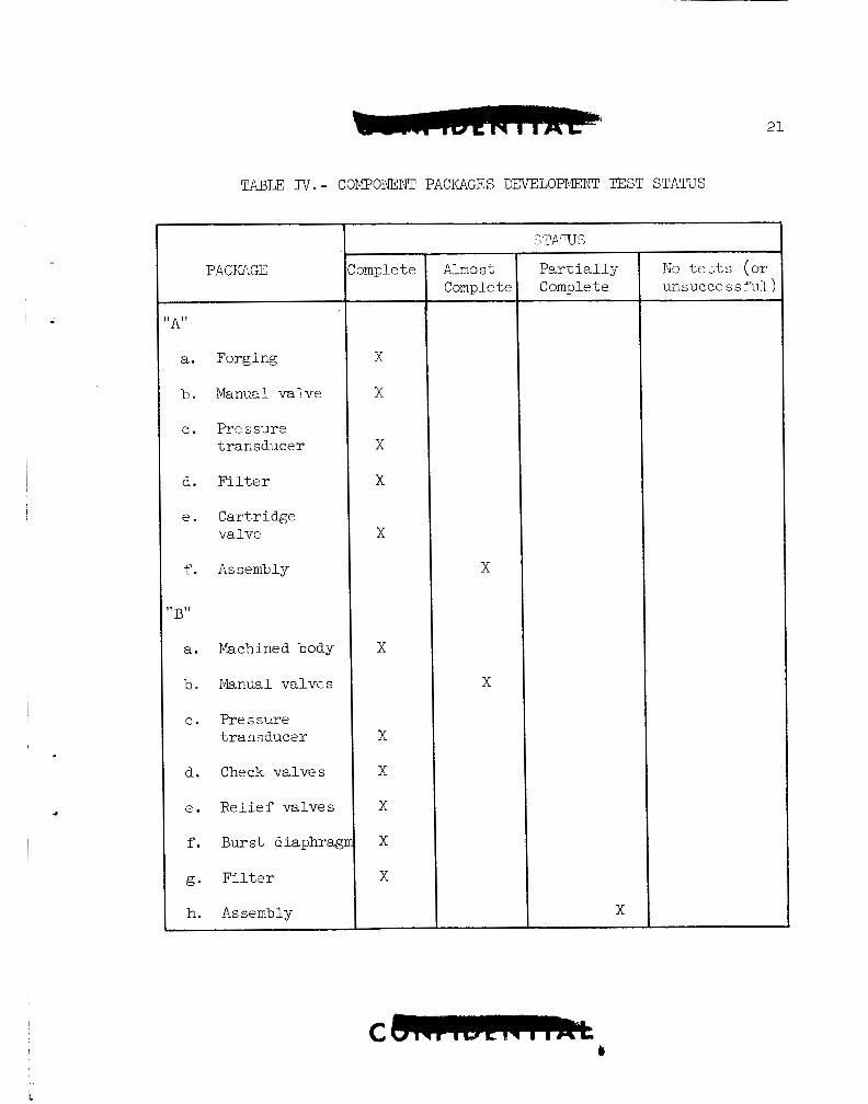
Components. - Two design changes have been incorporated i n t h e following:
a. The "C" and "D" component package housings are being changed f r o m cas t ings t o machined pieces .
b. The s h a f t s e a l of t h e manuzl va lves of a l l c o n t r o l packages were changed Cram a s p l i t t e f l o n O-ring t o an omniseal.
Development Tes t ing
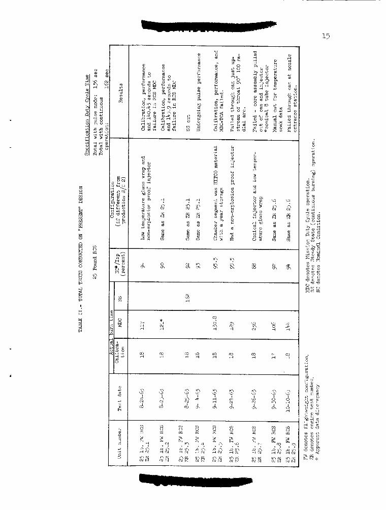
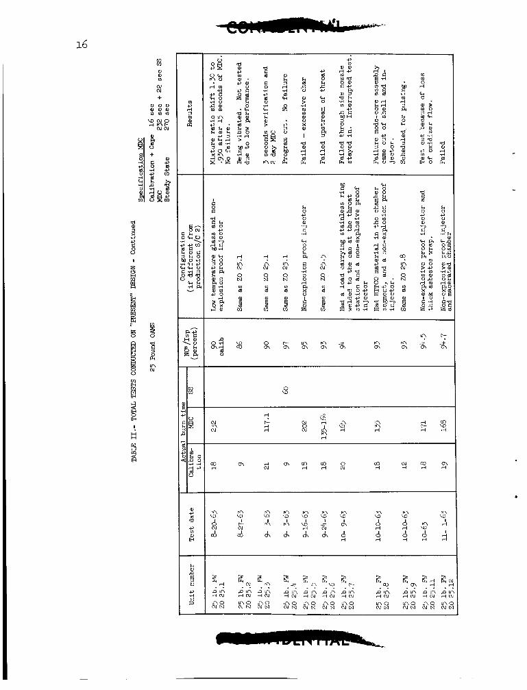
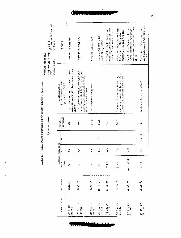
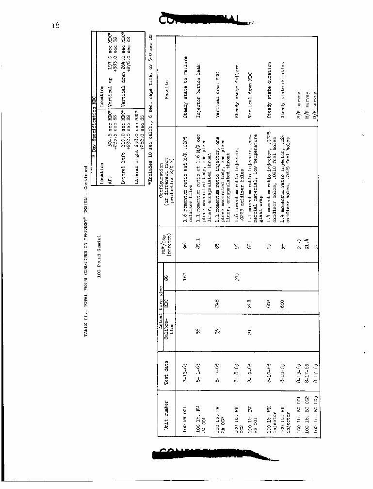
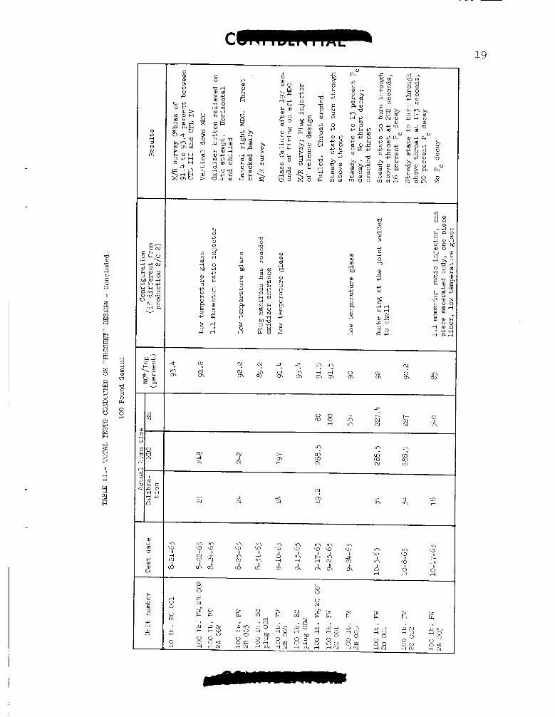
Thrust Chamber Assemblies.- A l l t e s t s which have been repor ted t o --------- Gemini Program Off ice during t h i s r epor t ing per iod are t abu la t ed i n t a b l e 11, along wi th pe r t inen t da t a concerning t h e tests. A s w i l l be noted from t h e table, ve ry l i t t l e t e s t i n g occurred during November 1963. s ince t h e duty cyc les were being r ev i sed by McDonnell Aircraf't Corpo- r a t ion . Considerable e f f o r t on analyzing and p red ic t ing pnrformance o f t he s m a l l a b l a t i v e engine was expended by Rocketdyne, so t h a t g r e a t confidence ex is t s a t Rocketdyne on t h e i r a b i l i t y t o meet t h e new duty cyc les .
Rocketdyne d i d not f e e l ob l iga ted t o t es t during t h i s p r i o d
Spec i f ic knowledge on the remaining ove r -a l l program i s unavai lable . It i s t h e Gemini Program O f f i c e ' s understanding that t h e t e s t scope o?' t h e research and development program i s being reduced, bu t t h e ex ten t i s not known.
Table I11 swnmarizes the s t a t u s of a l l TCA's. Rocketdyne considers t h a t t he i n s u f f i c i e n t l i f e f o r t he 25-pound and 100-pound OAMS TCA's pu lse performance demonstration, and excess s k i n temperatures are t h e remaining engine t e c h n i c a l problems t o be resolved.
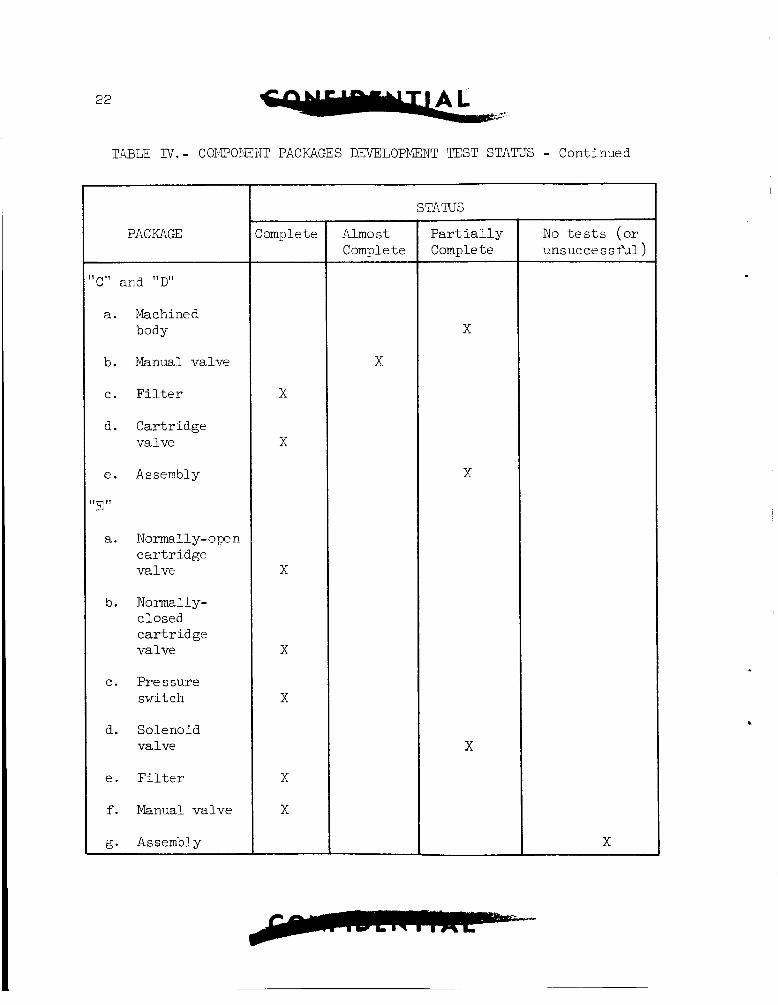
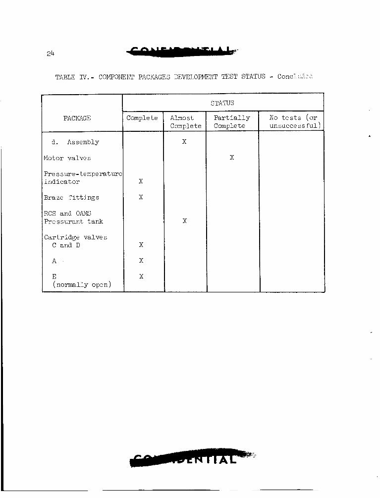
Components.- The tes t s t a t u s o f a l l components i s presented i n t a b l e IV.
29
System Test ing
110 t e s t s were conducted during t h i s r e p a r t i n g per iod as a r e s u l t of t h r u s t chamber unava i l ab i l i t y . Although two f l ightwe i g h t systems, one each of t h e RCS and O , W , have been assembled, i n i t i a t i o n of t e s t i n g i s pending engine a v a i l a b i l i t y . e f f o r t o f t h i s group a t Rocketdyne. Thus, system t e s t s which remain t o be conducted ars unchanged from the previous r e p o r t .
System a n a l y s i s c o n s t i t u t e s the prime
Q u a l i f i c a t i o n Tes t ing
TTo qualif'ication t e s t s have been conducted during t h i s period. However, t e s t p lans are being prepared by Rocketdme and are being reviewed by McDonnell Aircraft Corporation. ?Tone are approved a t t h e present t i m e .
AGE
All aerospace ground equipment (AGE) f o r S p x e c r a f t Systems Test and p r e - i n s t a l l a t i o n acceptance has beer, de l ivered . Approximately 45 percent o f t h e requi red AGE for Cape Kennedy has been de l ivered and about 20 percent has been del ivered t o t h e pad. Del ivery of a l l u n i t s should be complete by the end of t he next s t a t u s r epor t ing per iod. The present d e l i v e r y s t a t u s i s shown i n table V.
A number o f spacecraf t changes have imposed new requirements on several o f t h e pyrotechnic devices, t hus r equ i r ing redes ign and addi- t i o n a l development t e s t i n g . drogue parachute i n the landing sys ten has l e d t o the i n i t i a t i o n of a development program for a drogue mortar. components t o a l l o v underwater functioning w a s completed. Redesign has a l s o overcome out-of-tolerance t i m e de lays f o r horizon scanner release. Weight increases i n the seat system have requi red redes ign of t h e sea t - e j ec to r rocke t t o increase i t s t h r u s t .
The new requirement for t h e a d d i t i o n of a
Redesign o f t he landing gear
A h igh r e j e c t i o n rate on the c a r t r i d g e s for t h e OUG and r e e n t r y con t ro l system valves has l e d t o t h e i r redesign.
Spacecraf t thermodynamics s tud ies have ind ica t ed t h a t t he shaped charges may be subjected t o temperatures which could cause the decom- pos i t i on of t h e i r explosives . As a r e s u l t of t hese s tud ie s , the sha-ped
39
charge:; vi11 be redesigned t o use t h e high-temp2rature-resistant explosive, "Dipan". Developmental t e s t i n g o f t he shaped charges using thc new loading dens i ty , lower-bri sance "Dipan" has begun. Deve lopen t o f t h e hatch a c t u a t o r f o r t h e paragl ider conf igura t ion was i n i t i a t e d . This design w i l l a l low manual release o f t h e l a t ch . F inanc ia l d i f f i - c u l t i e s 01' t h e a c t u a t o r vendor, who i s a l s o the vendor f o r t he emergency docking re lease and the docking bar assembly, have l e d t o development and production delays. The f i n a n c i a l problems have been overcome and the conduct o f t hese developments has resumed.
The tubing c u t t e r - s e a l e r s are now meeting s?cc i i ' ication leakage rzquirements through use of' increased tube-wall th ickness .
R e l i a b i l i t y assurance t e s t s have begun on t h e Z 100.75 separa t ion assembly, rendezvous and recovery separa t ion assembly, g u i l l o t i n e s , and mild detonat ing fuse i n i t i a t i o n system.
I n i t i a t i o n of q u a l i f i c a t i o n t e s t i n g of t he horizon scanner f a i r i n g r e l e a s e , pyrotechnic switches, and landing-gear-door j e t t i s o n system a w a i t de l ive ry of parts.
LANDING AND RECOVERY SYSTEPG
Parachute Recovery Systec;
On Septenber 3, 1963, t h e y u a l i f i c a t i o a drop t e s t program of t h e Gemini Parachute Recovery System w a s suspended t o permit t h e incorpora- t i o n of a h igh -a l t i t ude s t a b i l i z a t i o n parachute i n t o t h e recovery sys- tem. Incorpora t ion of t h e s t a b i l i z a t i o n parachute w a s deemed necesrary t o in su re spacecraf t s t a b i l i t y i n t h e event of' a malfunction i n LLiie
e l e c t r o n i c s a s soc ia t ed with t h e automatic s t a b i l i z a t i o n systerl arid a l s o t o permit dumping of t h e RCS propel lan ts p r i o r t o deploynent of t h e main recovery parachute . Preliminary des ign s t u d i e s have been completed and t h e de t a i l design i s underway. The sequence of opera t ion of t h e re - v i s e d recovery sysierr, w i l l be as fol lows:
1. Deployment of t h e s t a b i l i z a t i o n parachute a t 50,000-foot a l t i t u d e by t h e a s t ronau t .
2 . Release of t h e s t a b i l i z a t i o n parachute a t 10,600-foot a l t i t u d e This a c t i o n deploys t h e 18.3-foot p i l o t parachute by by t h e a s t ronau t .
means of a lanyard between t h e s t a b i l i z a t i o n parachute riser and.t l ie p i l o t parachute deployment bag. A f t e r deployment of t h e p i l o t parachute, t he s t a b i l i z a t i o n parachute remains permanently a t t ached t o t h e apex of t h e p i l o t parachute .
3 . Two and one-half seconds after t h e s t a b i l i z a t i o n parachute release, t h e rendezvous and recovery s e c t i o n i s separated from t h e space- c r a f t which, i n tu rn , allows t h e deployment of t h e 84.2-foot main re- covery parachute .
4 . Three and one-half seconds after t h e rendezvous and recovery s e c t i o n separa tes , t h e 18.5-foot p i l o t parachute disreefs slowing t h e descent rate of t h e rendezvous and recovery s e c t i o n and minimizing t h e p o s s i b i l i t y of contac t between the rendezvous and recovery s e c t i o n and t h e 8 4 . 2 - foo t parachute .
5 . Ten seconds a f t e r 84.2-foot parachute deployment, d i s r e e f occurs, ' slowing t h e spacecraf t t o a descent rate of approximately 30 feet per second ( co r rec t ed t o sea l e v e l ) .
/ 0 . After 84.2-foot parachute disreef, t h e as t ronaut i n i t i a t e s s i n g l e
po in t release.
-,. Twenty-two seconds a f t e r i n i t i a t i o n of s i n g l e poin t release, t h e release ac tua te s and t h e spacecraf t i s r eo r i en ted t o t h e 35' nose-above- the -hor i zon ta l a t t i t u d e . This a t t i t u d e minirnizes t h e impact acce le ra t ions
32
8. M t e r ir?pact t h e a s t ronau t disconnects the % .2-foot parachute tiirough the w e of a pyrotechnic-operated disconnect .
Present schedules i n d i c a t e t h a t the ipcorporat ion of t h e s t ab i l i - za t ion parachute w i l l rlot be accomplished u n t i l spacecraf t 5. Ii i s an t i c ipa t ed t h a t the present recovery system w i l l have t o be used f o r :;pacecraft 2 . A drop t e s t program has been formulated t o develop t h e f t a b i l i z a t i o n parachdte and t o qua l i fy t h e rev ised recovery systerri. The progym. i s t o be accor:lplished i n t h r e e phases. t h e lanyard deployment of' t h e 18.3-foot p i l o t parac l ide by the perman- e n t l y a t tached s t a b i l i z a t i o n parachute . T h i s phase w i l l use bo i l e r - p l a t e 'j as a t e s t veh ic l e . Tests a r e scheduled t o begin t h e f i r s t week of' Jamary l9dt and t o continue i n t o February 1964. velop t h e s t a b i l i z a t i o n parachute. From these tes ts , the r ee f ing parani- e t e r s for the parachute w i l l be determined and t h e s t r u c t u r a l i i i t e g r i t y of' the parachute demonstrated. An instrumented weight bonh (Pl'V) w i l l be used as t h e t e s t vehic le f o r t h i s phase. Tes t ing f o r t h i s phase i s scheduled t o begin about March I, 1964, and be completed i n August 1964. Phase I11 w i l l be composed of complete-system drops and w i l l be used t o qua l i fy the recovery systenl. S t a t i c a r t i c l e 7 w i l l be used as t h e test veh ic l e and w i l l contairl a production recovery system. This phase of' t e s t i n g should begin i n J u n e 1964 and be completed i n October 1964.
Phase I w i l l develop
Phase I1 w i l l de-
I f the present recovery system (minus drogue parachute) i s used on spacecraf t 2, t h e q u a l i f i c a t i o n of t h a t system w i l l be resumed. Three drops a r e present ly being planned, using s t a t i c a r t i c l e 7, t o complete q u a l i f i c a t i o n of t h e system. and be completed by the end of March 1964.
These drops should Legin i n February 1964
Paragl ider Parachute Recovery System
The f i r s t of two i n f l i g h t t e s t s , using a Gemini b o i l e r p l a t e vehic le , t o demonstrate t h e adequacy of modif icat ions t o t h e pa rag l ide r parachute recovery system w a s conducted a t E l Centro, Cal i forn ia , on November 1.2, 1965. This t e s t v e r i f i e d wind tunne l resu l t s concerning t h e r e loca t ion of' t h e drogue parachute attachment and t h e incorpora t ion of t h e impact- a t t enua t ion pad wi th in the veh ic l e contours . The b o i l e r p l a t e , wi th t h e drogue parachute deployed, demonstrated adequate s t a b i l i t y during t h e t es t and a l l equipment w a s recovered i n s a t i s f a c t o r y condi t ion . The f i n a l t e s t i s scheduled f o r t h e f i r s t week i n Decenber 1963. cliould complete the q u a l i f i c a t i o n of t h e paragl ider parachute recovery cystem.
T h i s
Paragl ider Larding S y s t e r
Half-Scale Tow Tests.- Groond tow t e s t i n g a t Edwards A i r Force Base, using t k e ha l f - sca le b o i l e r p l a t e vehic le , w a s conlpleted by t h e F l i g h t Recearch Center on October 12, 1-96?. rlade with t h e last 43 tow runs bei,ng conducted during t h i s r epor t ing pcr iod . tlie remainder were made using a s p e c i a l t e s t autor*.ouile as t h e towing v e h i c l e . These rxns were conducted t o i n v e s t i g a t e veh ic l e l i t ' t -ofi ' c h a r a c t e r i s t i c s , he l i cop te r t o w techniques, and t h e eff'ects of W : L ~
kcnding da3.n.g high cpeed towc. Vehicle a t t i t u d e under i n i t i a l condi- t i o n s of -10" and 19" had no spprec iab le inf luence on the l i f t - o f f char- a c t e r i s t i c s . No he l i cop te r downwash problems werc tncountercd u i t h thr. technique developed f o r t h i s type o f tow. And the keel bcnding, 3,; mc-3;- ured by inclinometers, w a s cor re la ted i i i t h da t a obtained during ha i r - sca l e and f u l l - s c a l e wind tunnel t e s t s conducted a t Ames Research Center.
A t o t a l or' 180 te , i s were
O f t h e l a t te r , 12 runs were made us ing t h e CII-4CA iielicopter.;
Tow Test Vehicles ("V) .- A design engineer ing i m p e c t i o n ( D E I ) arld hardware review were he ld a t North American Aviation, Space and InI'orma- t i o n Systems Division, on September 27, 1963. A t o t a l oi' j3 Request f o r A l t e r a t i o n (RFA's) was submitted. O f t hese , 24 were placed i n Catc- gory I (mandatory), 5 i n Category I1 ( s tudy) and 6 were r e j e c t e d by tl:c board.
All appl icable RFA items were incorporated on !ITV 1 and manu- f a c t u r i n g and assembly of t he vehic le were corr,pleted during t h i s repor t - ing per iod . The veh ic l e w a s t ranspor ted t o Edwards A i r Force Base on November 26, 1963, prepara tory t o commencing t h e f l i g h t t e s t program. TTV 2 i s running approximately one month behind TTV 1. The m a i n s t ruc - t u r e w a s removed f r o m t h e assembly j i g on October 16, 1963. shortages, notably i n t h e Paragl ider Control Actuation (PCA) System, may cause schedule s l ippage .
P a r t s
Ground tow t e s t s of t h e T T V 1 (without wing) are scheduled t o start during t h e f i r s t ha l f of December 1963. expected p r i o r t o t h e end of January pending r e s u l t s of f u l l - s c a l e wind tunne l t e s t s of t h e wing and a v a i l a b i l i t y of a f l i g h t - q u a l i f i e d PCA f r o n Vickers, Inc .
The f i r s t manned f l i g h t i s
Fu l l - sca l e Test Vehicle (FSTV).- Fabr i ca t ion and assembly of t h e FSTV's have been completed and all DEI items have been worked o f f . FSTV 2 should complete a combined systems t e s t and a ground dynamic wing deployment during t h e f i r s t week of December 1963. t o s h i p t h i s veh ic l e t o Edwards A i r Force Base immediately following t h e wing deploynent . The f i rs t i n f l i g h t d e p l o p e n t i s a n t l c i p a t e d dur ing t h e l as t ha l f of December 1963.
It i s planned
FSTV 1 is approximately t e n ~
working days behind FSTV 2.
34
Hzlf-Scale Development Tests . - A s e r i e s 01' drops of a ha l f - sca le wing a n d vehicle w a s begun during t h e repor t ing per iod a t blSC. These t e s t r , are being conducted as an in-house inves t iga t ion i n t o p o t e n t i a l problerr. a reas , independent of North American Avia t ion ' s e f f o r t s , during t h e deployment phase of t h e pa rag l ide r . Basic aerodynamic parameters and qua l i t a t ive s t a b i l i t y c h a r a c t e r i s t i c s a r e being obtained. The f i r s t drop, conducted over Galveston Bay, on November 14, 1963, ind ica ted sat- i s f a c t o r y s t a b i l i t y of t h e t e s t vehic le with t h e wing i n t h e inver ted "U" condition of deployment. Addit ional t e s t s are planned f o r t h e month of December 1965 t o s tudy t h e deployment t r a n s i t i o n from t h e "U" con- d i t i o n t o the "L" condi t ion t o s teady state g l i d e .
Prototype Wings.- Fabr ica t ion of prototype w i n g s on t h e s o f t t o o l i n g was discontinued a f t e r completion of wings nos. 201 and 202. Wing no. 203 was not completed because of an excessive number of d i screpancies , and t h e pa r t s were r e l ega ted t o t es t samples. The improved hard t o o l i n g w a s completed by t h e end of September 1963 and wings nos. 204 and 205 were f ab r i ca t ed with t h i s t o o l i n g . Wing no. 201 w a s used i n t h e i n i t i a l f u l l - s c a l e t es t i n t h e Ames Research Center wind tunnel . Wing no. 202 w a s used f o r packing tes t s and w i l l be used f o r FSTV dynamic sequencing ground t e s t s . drops and wing no. 205 f o r i n i t i a l TTV f l i g h t s . t h e keel-spreader ba r and boom-Epreader bar b u r s t a t 50.6 p s i and 35.0 ps i , respec t ive ly .
Present p lans are t o u s e wing no. 204 f o r i n i t i a l FSTV Burst t e s t specimens of
Wing no. 206 i s i n t h e f i n a l s t ages of f a b r i c a t i o n .
Paragl ider In t e r f ace . - A separa te addendum t o t h e paragl ider i n t e r - race meeting minutes w a s c r ea t ed t o de f ine a c t i o n i t e m s , problem areas, and incompa t ib i l i t i e s between t h e Gemini pa rag l ide r design program and items developed t o support t h e e x i s t i n g North American Aviation para- g l i d e r research and development program.
McDonnell A i r c r a f t Corporation i n i t i a t e d a design e f f o r t on t h e l o c a t i o n and i n s t a l l a t i o n of t h e Gemini pa rag l ide r t r i m con t ro l s . con t ro l schematic por t ion of a McDonnell A i r c r a f t Corporation drawing f o r s t a t i c a r t i c l e 2 w a s reviewed by North American Aviat ion and McDonnell A i rc ra f t Corporation, and b a s i c agreement w a s reached on t h e i n t e r - connection of t h e t r i m pots , ree l pos i t i on pots , and hand c o n t r o l l e r p o t s .
The
McDonnell A i rc ra f t Corporation t r ansmi t t ed a document (no. 233-1(-383), L i s t ing of Weights, Centers-of-Gravity and Radius of Gyration f o r Para- g l i d e r System Components, t o North American Aviat ion. North American Aviation t r a n s n i t t e d thermal conduct iv i ty c o e f f i c i e n t s f o r t h e packed wing t o McDonnell A i r c r a f t Corporation f o r i nc lus ion i n t h e i r thermal ana lys i s of t he paragl ider i n s t a l l a t i o n .
I -
I -
The rc-ajority 01' t h e goverment furn ished equipnlent (GFE) t o be provided t o Yortl- Arnericarl Aviation for t he pa rag l ide r research and developrnent program has been shipped. McDonnell A i r c r a f t Corporation w a s not i f ' ied of t he rev ised GFE reqdirements r e s v l t i n g fronA t h e Gerilini Program Ofi ' ice dec is ion t o e l iminate t h e r e t r o f i t of t h e f u l l - s c a l e t e s t veh ic l e s (FSTV) t o t h e G e m i n i conf igura t ion .
The paragl ider c o n t r a c t o r ' s weight s t a t u s r epor t s f o r t h e nAonths of Septerr-ber and October 1965 were t ransmi t ted t o t h e spacecraf t contractor. €or incorporat ion i n t o t h e spacecraf t weight s t a t e c e n t s .
The paragl ider i n t e r f a c e n-eetings were c u r t a i l e d as a result of t h e GelrLni Program Office dec i s ion t o concentrate on t h e parag l ider research and development program. Minimum i n t e r f a c e coordinat ion w i l l be main- t a i n e d and i n t e r f a c e meetings ca l led on an "as required" b a s i s .
E?~VIXOKM.ETd"AL COITIXOL SYSTEN (ECS)
' jj-sterrl development t e s t i n g a t AiResearch has been completed without any s i g n i f i c a n t problem areas. Dynamic and environmental q u a l i f i c a t i o n t e s t i n g has s t a r t e d . Temperature-alt i tude q u a l i f i c a t i o n t e s t i n g is scheduled t o start during t h e next r epor t ing per iod. Delays have been encountered from problems i n f i r s t a r t i c l e manufacture and component redes igns .
Bo i l e rp l a t e 2, a t McDonnell A i r c r a f t Corporation, i s i n manufacturing
Manned bui ldup t o i n s t a l l t h e complete ECS. per iod w i l l include a 2-day manned run, and a 14-day unmanned run . and unmanned h igh-a l t i tude e j ec t ion t e s t s on t h e egress k i t w i l l a l s o be made. The b o i l e r p l a t e w i l l be shipped t o MSC at t h e completion of t h e above t e s t s .
Tes t ing during t h e next r epor t ing
Several changes have been made t o t h e ECS during recent months. The coolant f l u i d w a s changed from OS 139 t o MSC 198 t o reduce system pressure drop and t h e r e f o r e power consumption during low-heat-load con- d i t i o n s . Launch hea t ing s tud ie s ind ica ted a need f o r a d d i t i o n a l r e s e r v o i r volume t o allow f o r coolant expansion. The 53-cubic-inch s i z e w a s chosen t o u t i l i z e t h e same i n t e r n a l components as the e x i s t i n g r e s e r v o i r . Space- c r a f t volume r e s t r i c t i o n s precluded enlargement of t h e e x i s t i n g r e s e r v o i r without s i g n i f i c a n t i n s t a l l a t i o n redes ign . The o u t l e t duct of t h e launch cool ing heat exchanger ?as been modified t o c i r c d a t e hot coolant around t h e duct , thus rnaintaining t h e duct w a l l s above f reez ing temperatures . IJater dumping t e s t s conducted a t AiResearch ind ica ted p o t e n t i a l freeze u.p during l i q u i d danp opera t ion .
A 53-cubic- inch r e se rvo i r has been added t o each coolant loop.
The production
The u n i t s de l ivered
i'l ight un i t s i in les r;
arc- required.
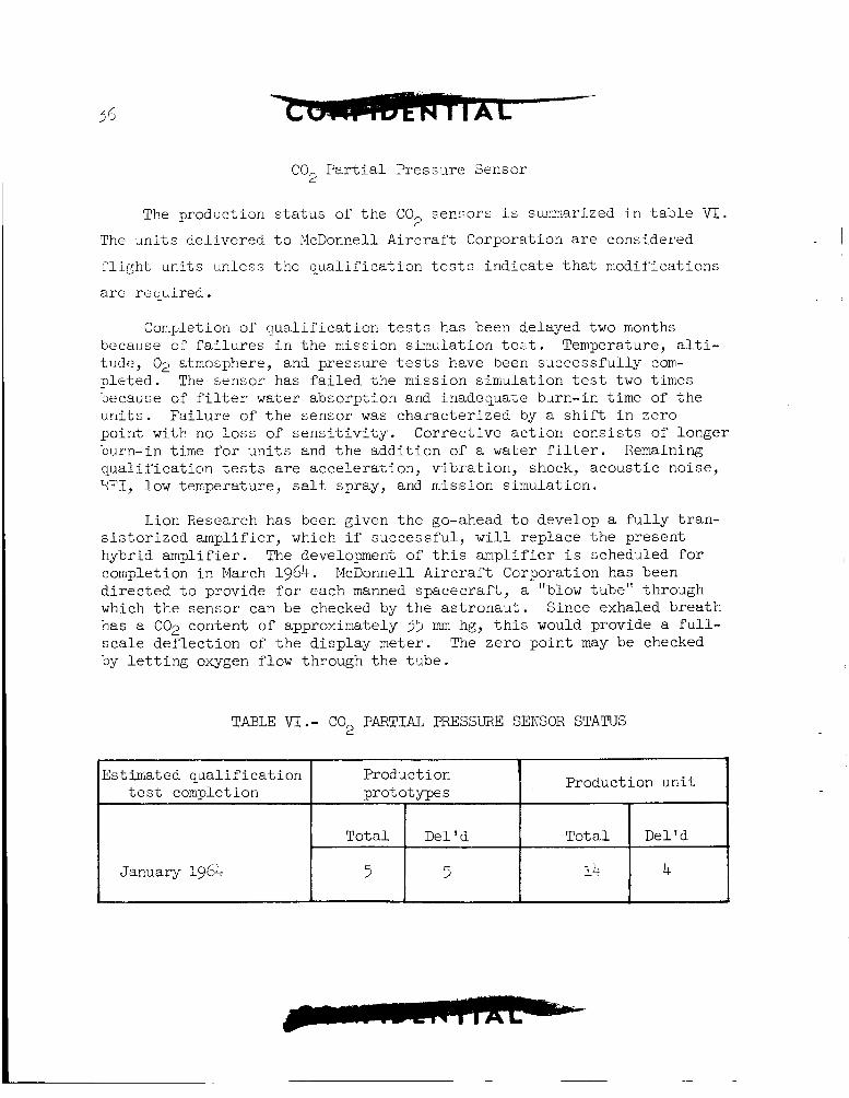
E s t h a t e d q u a l i f i c a t i o n Product ion Production un i t t e s t coniple t i on p ro t oty-pes
To ta l Del'd T o t a l Del 'd
January 1964 5 5 14 4 -
C 0 2 P a r t i a l Pressure Sensor
s t a t u s of t h e COP sensors i.s sunmarized i n t a b l e V I .
t o McDonnell A i r c r a f t Corporation are considered
t h e q u a l i f i c a t i o n t e s t s i n d i c a t e t h a t niodif 'ications
Cor@etion of q u a l i f i c a t i o n t e s t s has been delayed two months because of f a i l u r e s i n t h e mission s imulat ion t e L t . Temperature, a l t i - t i u k , 02 atmosphere, and pressure t e s t s have been success fu l ly com- p le t ed . The $,ensor has fa i led t h e mission s imulat ion t e s t two times because of f i l t e r water absorpt ion and inadequate burn-in t i m e of t h e u r i i t s . Fa i lu re of t h e sensor w a s charac te r ized by a s h i f t i n zero poin t w i t h no loss of s e n s i t i v i t y . Correct ive a c t i o n c o n s i s t s of longer burn-in t i m e f o r u n i t s and t h e add i t ion of a water f i l t e r . Remaining q u a l i f i c a t i o n tests are acce lera t ion , v ib ra t ion , shock, acous t i c noise , HFI, low temperature, salt spray, and mission s imula t ion .
Lion Research has been given t h e go-ahead t o develop a f u l l y t r an - s i s t o r i z e d ampl i f ie r , which i f successfu l , w i l l r ep lace t h e present hybrid ampl i f ie r . The development of t h i s ampl i f i e r i s scheduled f o r completion i n March 1964. d i r e c t e d t o provide f o r cach manned spacecraf t , a "blow tube" through which t h e sensor can be checked by t h e a s t r o n a u t . Since exhaled b rea th has a CO;! content of approximately 33 mm hg, t h i s would provide a f u l l - s c a l e de f l ec t ion of t h e d i sp lay meter. The zero po in t may be checked by l e t t i n g oxygen flow through t h e tube .
McDonnell Aircrai't Corporation has been
TABLE V I . - C02 PARTIAL PRESSURE SENSOR STATUS
PRESSURE SUIT
The f i n a l eva lua t ion o f t h e G2C prototype s u i t was conducted during September and October 1963. Astronaut eva lua t ion i n the Gemini engineer- ing mockup a t McDonnell A i r c r a f t Corporation ind ica ted t h a t most of t he previous fi t-problems had been corrected. Basic mobi l i ty i n t h e s u i t w a s s a t i s f a c t o r y , although a few i s o l a t e d pressure po in t s caused discomf'ort which could not be t o l e r a t e d f o r long term wear. I n view of t h e f i t problems which have occurred, f i n a l f i t t i n g s w i l l be made a t t h e David Clark Company p r i o r t o de l ive ry of a l l fu tu re s u i t s .
Several problems were encountered i n t h e helmet and v i s o r design. Modif icat ions have been d i r e c t e d t o e l imina te cracking o f t he v i s o r , t o reduce t h e v i s o r ac tua t ing forces , and t o provide a p o s i t i v e l a t c h r'or t h e v i s o r i n the closed pos i t ion . The in t e r f e rence between t h e seat back- board and t h e helmet which w a s reported previously, w a s checked and confirmed. The spacecraf t cont rac tor w a s d i r e c t e d t o modify t h e back- board contour s l i g h t l y t o e l imina te the in t e r f e rence . To preclude Turther i n t e r f e rence problems, the helmet contour and neck r i n g diameter were f rozen a t t h e present s i z e and e x t e r n a l configurat ion.
Evaluat ion of t h e e l e c t r i c a l and e l e c t r o n i c compa t ib i l i t y OS t he pressure s u i t communications and biomedical equipment i n t h e compatibil- i t y t e s t u n i t w a s s a t i s f a c t o r y . An eva lua t ion of t h e compa t ib i l i t y of t he s u i t wi th the environmental cont ro l system i n b o i l e r p l a t e 2 was a l s o s a t i s f a c t o r y . Oxygen flow, cooling, and v e n t i l a t i o n were s a t i s f a c t o r y i n a l l po r t ions of t he s u i t except t h e gloves. The w r i s t disconnect r i n g s are being redesigned t o incorporate i n t e g r a l vent po r t s . Improved glove v e n t i l a t i o n i s expected.
I n eva lua t ing t h e s u i t flow c h a r a c t e r i s t i c s , it w a s e s t a b l i s h e d t h a t t h e present l o c a t i o n of t h e pressure sensor f o r t he s u i t pressure r e g u l a t o r could cause a negative pressure i n the s u i t i n comparison wi th cabin pressure. This condi t ion i s not compatible wi th t h e s u i t des ign and would cause excessive pressure drop and leakage i n t o t h e s u i t from t h e cabin. To preclude t h i s condi t ion, t he environmental con t ro l system opera t ing procedures are being rev ised t o leave the cabin r e c i r c u l a t i o n valve open during normal o r b i t opera t ions . This mode of opera t ion w i l l a l s o minimize the l i ke l ihood of CO bui ldup i n t h e s u i t .
2
A prototype ou te r cove ra l l incorporat ing an in t eg ra t ed parachute harness and in t eg ra t ed l i f e v e s t w a s evaluated. harness requi red t h e add i t ion of l e g and t o r s o s t r a p adjustment buckles which compromised the f i t of the harness and caused discomfort. t h e present f i t t e d harness i s acceptable , no f u r t h e r e f f o r t on t h e
I n t e g r a t i o n of t h e
Since
38
i n t eg ra t ed harness i s planned a t t h i s time. The in t eg ra t ed l i f e vest was not e n t i r e l y sa t i s f ac to ry , but the b a s i c concept i s favored as t h e bes t means for providing personal f l o t a t i o n . A l i f e vest which can be worn continuously i s being developed by the Crew Systems Division. a s a t i s f a c t o r y design i s achieved, t h e vest w i l l be in t eg ra t ed i n t o t h e s u i t , i f possible .
Once
Dzl iver ies of t h e G2C t r a i n i n g s u i t s a r e now i n process. S u i t s f o r t he parachute jump t e s t s and the f i n a l e j e c t i o n seat development s l e d tes t s have been del ivered. The f i rs t two as t ronau t t r a i n i n g s u i t s are rcady f o r the f i n a l f i t t i n g s wi th d e l i v e r y expected i n e a r l y December 1963. The remainder of the a s t ronau t t r a i n i n g s u i t s are scheduled f o r de l ive ry i n December 1963 and January 1964. These d e l i v e r y schedules are compatible wi th present program requirements.
GUIDANCE AND CONTROL SYSTEM
ATTITJDE AJlD CONTROL MANEWER ELECTRONICS (ACME)
During t h i s repor t ing period, the Aerospace Ground Equipment (AGE) de l ivered i n support of' t h e ACME systems w e r e t he p r e - i n s t a l l a t i o n acc&ance (PIA) t e s t console and spacecraf t s y s t e m t e s t console, t oge the r with supporting adapters and t e s t boxes. The d e l i v e r y of t he ACME system for spacecraf t 2 and t h e compa t ib i l i t y t e s t un i t were com- pleted. Two u n i t s are continuing i n the qualiT-ication program. During v i b r a t i o n t e s t s on q u a l i f i c a t i o n u n i t 1, the mounting b o l t (Calfax f a s t e n e r s ) f o r t h e ACE and OAME packages f a i l ed . McDonnell A i r c r a f t Corporation and Honeywell are designing several f ixes and hope t o have a design re leased by mid-December 1963. a l r eady de l ivered w i l l continue i n t e s t u n t i l a n appropr ia te r e t r o f i t schedule can be es tab l i shed .
Uni t s o f t h e ACME systems
During t h i s period, t h e acceptance t e s t e r used in-house a t Honeywell has been out of se rv ice s ince September 17, 1963. During t h i s p i r i o d a l l modif icat ions and design improvements are being incorporated i n t o the production AGE. completed on November 9, 1963. following week and t h e ACE and OAME packages f a i l e d during t e s t c a l i - b r a t i o n period. Rate gyro and power i n v e r t e r packages d id not e x h i b i t any v ib ra t ion problems. I n q u a l i f i c a t i o n u n i t 2, t he e l e c t r i c a l and e l e c t r o n i c in t e r f e rence tes t s have s t a r t e d and w i l l be completed p r i o r t o December 21, 1963.
Low-temperature t e s t s on q u a l i f i c a t i o n u n i t 1 w e r e The v i b r a t i o n tes t s were s t a r t e d t h e
39
The compa t ib i l i t y t e s t u n i t tes ts on ACME a t McDonnell A i r c r a f t Corporation have been completed. F l i g h t ACbE packages f o r incorpora t ion i n the pa rag l ide r con t ro l system were shipped t o North American Aviat ion f o r use i n the ;'light t e s t vehicle.
INERTIAL GUIDANCE SYSTEM
Computer
The t h i r d engineer ing prototype de l ive red t o Mcnonnell A i r c r a f t Corporation f o r use i n the compat ib i l i ty t e s t u n i t t es t s uncovered a number of noise and spacecraf t grounding problems. compa t ib i l i t y t es t u n i t and the e l e c t r o n i c systems t e s t u n i t t o represent spacecraf t wir ing more c l o s e l y i s being accomplished. This w i l l a l low a d d i t i o n a l e rg inee r ing t e s t i n g t o overcome i n t e g r a t i o n problems p r i o r t o the start of spacecraf t systems t e s t (SST). The no. 4 IGS f o r spacecraf t 2, incorpora t ing the f l i g h t conf igura t ion computer, w a s shipped t o McDonnell Aircraf ' t Corp., on November 29, 1965 Computer no. 5 has undergone extensive v i b r a t i o n testing and a nwnber of v i b r a t i o n problems have been uncovered. Fc i lures have been i s o l a t e d t o the area of t h e cannon connectors and the so lde r connections t o connectors. A r e a l l o c a t i o n of computer de l ive ry schedules has been accomplished provid- i ng f o r a n early updating of IBM conf igura t ion con t ro l u n i t w i th t h e l a te r vers ion computer system t o provide IBM wi th a system t o check out engineer ing problems and f l i g h t hardware acceptance procedures. Two computer tes t consoles (AGE equipment) were de l ivered during the month o f November 1963. Temperature environmental t e s t s w i l l be s t a r t e d on t h e exp lo ra to ry q u a l i f i c a t i o n uni t during the next two weeks.
A rewiring of t h e
I n e r t i a l Measuring Unit
The product ion platform no. 1 f o r spacecraf t 2 SST, IGS (no. 4), Testing on t h e redesigned power supply w a s shipped October 24, 1963.
u n i t incorpora t ing improved regula tors , input power i s o l a t i o n , and separa te gimbal readout power e x c i t a t i o n have been accomplished a t blcDonne11 A i r c r a f t Corporation on the compat ib i l i ty test un i t . A s a r e s u l t of t hese tes t s , a f ina l design f o r t h e production power supp l i e s has been e s t ab l i shed . Af te r completion of these t e s t s a t Honeywell, the IMU system w a s shipped t o IBM fo r i n t e g r a t i o n i n t o IGS no. 4. Praduct ion platform no. 5 v i b r a t i o n tes t s a re cont inuing i n a n e f f o r t t o reduce t r a n s m i s s i b i l i t y t o the inner gimbal. excess ive gimbal o s c i l l a t i o n s have been observed and were caused by i n t e r a c t i o n of t he gyro exc i t a t ion and high-frequency gimbal c o n t r o l loops. and i s scheduled f o r a l l f l i g h t un i t s . Del ivery of r o t a r y components
During systems acceptance t e s t s ,
Th? design Pix cons is t ing of a notch f i l t e r has been acconplished
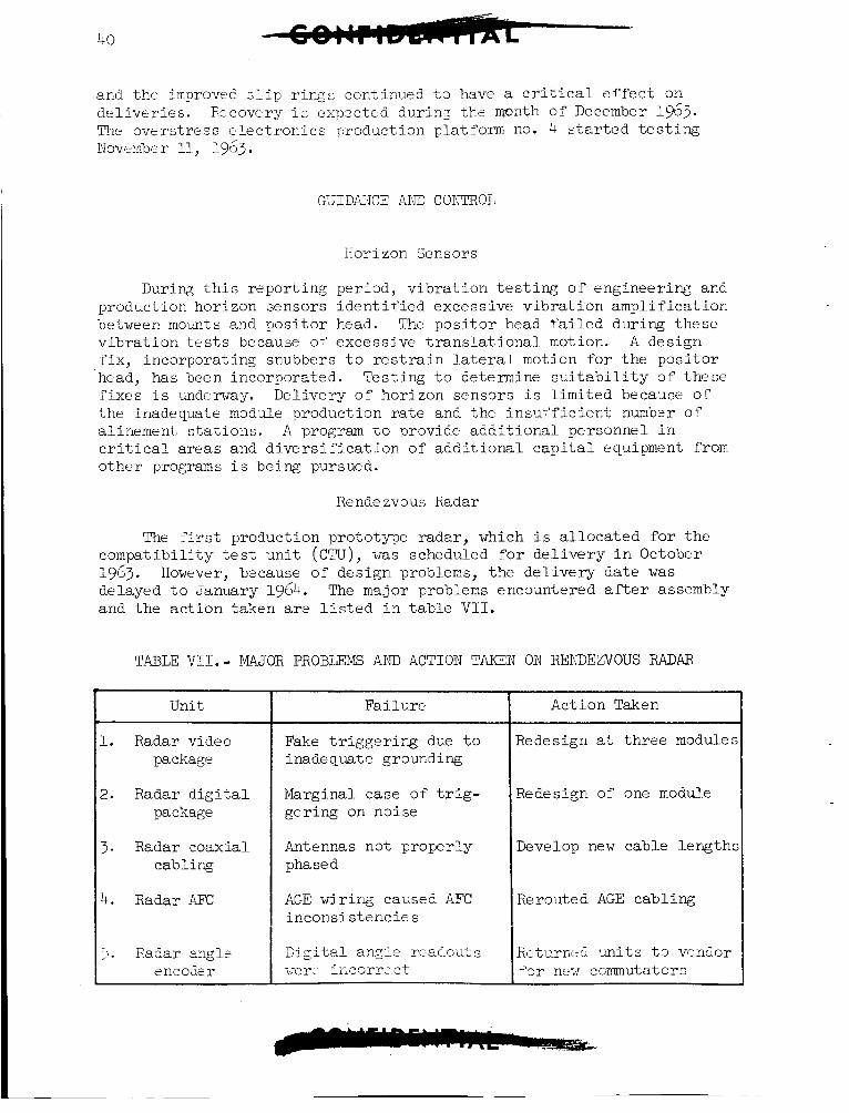
40
1. Radar video package
2. Radar d i g i t a l package
3. Radar coaxial cabling
ht. Radar AM:
and the improved s l i p rings continued t o have a c r i t i c a l e f f e c t on d e l i v e r i e s . Rccovtry i c expzctEd durinz th? month of December 1963. The overs t ress e l e c t r o n i c s production platform no. 4 s t a r t e d testing Novcmbcr 11, 1963.
GUIDANCE ANE CONTROL
Horizon Sensors
During t h i s r?por t ing pried, v i b r a t i o n t e s t i n g o f engineer ing and production horizon sensors i d e n t i f i e d excessive v i b r a t i o n ampl i f i ca t ion between mounts and p o s i t o r head. The p o s i t o r head T’ailcd during these v i b r a t i o n t e s t s because of’ excessive t r a n s l a t i o n a l motion. A design f i x , incorporat ing snubbers t o r e s t r a i n lateral motion f o r t h e p o s i t o r head, has been incorporated. Tes t ing t o determine s u i t a b i l i t y of‘ these fixes i s underway. Del ivery o f horizon sens3rs i s l imi t ed because 01- t h e inadequate module production rate and the insul’f ic ient numb?r of alinement, s t a t i o n s . A program t o provide a d d i t i o n a l personnel i n c r i t i c a l areas and d i v e r s i f i c a t i o n of a d d i t i o n a l c a p i t a l equipment from o the r programs i s being pursued.
Rende zvous Radar
The f i r s t production prototype radar , which i s a l l o c a t e d for t h e compat ib i l i ty t es t u n i t (CTLJ), w a s scheduled for d e l i v e r y i n October 1963. However, b2cause of des ign problems, t h e d e l i v e r y da t e w a s delayed t o January 1964. and the a c t i o n taken are l i s t e d i n table V I I .
The msjor problems encountered af ter assembly
T.4BLE VI1.- MAJOR PROBLEMS AND ACTION TAKEN ON RENDEZVOUS RADAR
Unit
:?. Radar angle I - encodsr
Fa i lu re
Fake t r i g g e r i n g due t o inadequate grounding
Marginal case of t r i g - ger ing on noise
Antennas not proper ly phased
AGE wir ing caused AFC incons i s t enc ie s
I Action Taken
Redesign a t t h r s e modules
Redesign of one module
Develop new cable l eng ths
Rerouted AGE cabl ing
Rttv.rnt.5 uni t2 t 3 vcndor >or n x ccrmutators
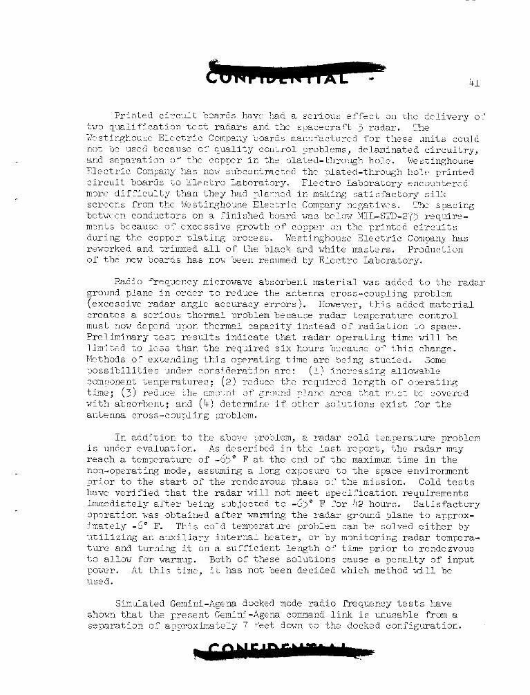
Pr in t ed c i r c u i t b3ards havt had a se r ious e f f e c t on The d e l i v e r y oi' two q u a l i f i c a t i o n t e s t r ada r s and the spacecraf t 3 radar . The IkstiDghouse E l e c t r i c Compariy boards manTPactured for thes? u n i t s could not be used because 0: q u a l i t y cont ro l problems, delaminated c i r c u i t r y , and separa t ion 0; t he copper i n the plated-through hole . Westinghouse E l e c t r i c Company has nov subcontractrd the plated-through hol t p r in t ed c i r c u i t boards t o E l e c t r o Laboratory. E l e c t r o Laboratory encountered m 3 r c d i f f i c u l t y than t h e y had rJlanned i n mzking s a t i s f a c t o r y s i l k screens from the lie s t i q h o u s e E l e c t r i c Company negat ivtTs. The spacing bztwc cn conductors on a f in i shed board w a s below MIL-STD-275 requi re - m3nts because o - ~ excessive growth o f copper on the pr in ted c i r c u i t s during t h e copper p l a t i n g process. Westinghouse E l e c t r i c Co-npany has reworked and trimmed a l l of t h e black and white masters. Production of t he new boards has nov been resumed by E l e c t r o Laboratory.
Radio frequency microwave absorbent material w a s added t o t h e r ada r ground plane i n order t o reduce the antenna cross-coupling problem (excessive r ada r angle accuracy e r r o r s ) . c r e a t e s a se r ious thermzl problem because r ada r temperature con t ro l must now depznd upon thermal capac i ty in s t ead o f r a d i a t i o n t o space. Pre l iminary t e s t r e s u l t s i nd ica t e t h a t r a d a r opera t ing t i m e w i l l be l in i l ted t o l e s s than t h e required s i x h o a x bccausc of t h i s charge. Methods of extending t h i s operat ing time are being s tudied . Some p o s s i b i l i t i e s under considerat ion are: (1) i n c r e a s i r g allowable component temperatures; ( 2 ) reduce the requi red l eng th of opera t ing t i m e ; (3 ) r e d w e xhe a r c ?+ 0' gr37ind nlane a r e a 'that : n > , ~ t bt covered wi th absorbent; and (4) determine i f o the r so lu t ions e x i s t Tor t h e antenna c ross -cmpl ing problem.
However, t h i s added material
I n add i t ion t o the above problem, a r ada r cold temperature problem i s under eva lua t ion . A s described i n t h e last r epor t , t h e r ada r msy reach a temperature o f -65" F a t the end of t h e maximum t i m e i n t h e non-operating mode, assuming a l o n g exposure t o t h e space environment p r i o r t o the start of the rendezvous phas? of t h e mission. Cold t e s t s have v e r i f i e d t h a t t he r ada r w i l l not meet s p e c i f i c a t i o n requirements immediately a ' t e r being subjected t o -6>" F ?or 42 hours. on3rat ion w a s obtained a f t e r warming t h e r ada r ground plane t o approx- imate ly -6" F. u t i l i z i n g an a u x i l i a r y i n t e r n a l hea te r , o r by mmi to r ing r ada r tempera- t u r e and turn ing it on a s u f f i c i e n t l eng th 0:' time p r i o r t o rendezvous t o allaw f o r warmup. Both of these so lu t ions cause a pena l ty of input power. used.
S a t i s f a c t o r y
This cold temperatme problem can be solved e i t h e r by
A t t h i s t i m e , it has not been decided which method w i l l be
Sim\dated Gemini-Agena docked mode r a d i o frequency t e s t s have shown t h a t t he present Gemini-Agena command l i n k i s unusable from a sepa ra t ion of a p r o x i m a t e l y 7 +eet down t o the docked configurat ion.
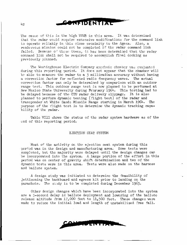
42
The cause of t h i s i s the high VSWR i n t h i s a rza . It w a s deterinined t h a t the radar would requi re extensive madi f ica t ions ?or t he command l i n k t o operate r e l i a b l y i n t h i s c lose proximity t o the Agena. Also, a rendezvous mission could not be completed i f t h e radar command l i n k f a i l ed . Because 01’ t hese items, it has been determined t h a t t h e r ada r command l ink s h a l l not be required t o accomplish f i n a l docking a s previously planned.
Thi Westinghouse E l e c t r i c Company anechoic chamber vas evn lmtcd during t h i s repor t ing period. It does not appear t h a t t he chamber w i l l bc ab le t o measure the r a d a r t o a 3 m i l l i r a d i a n accuracy without having a cor rec t ion f a c t o r f o r r e f l e c t e d r a d i o frequency waves. The a c t u a l co r rec t ion f a c t o r can only be determined by comparison with an outdoor range t e s t . This outdoor range t e s t i s now planned t o be performed a t New Mexico S ta t e Univers i ty during February 1964. This t e s t i n g had t o be delayed because of t h e CTU r ada r d e l i v e r y slippage. It i s a l s o planned t o perform dynamic t e s t i n g ( f l i g h t t e s t ) o f t he r ada r and transponder a t White Sands Miss i le Range starting i n March 1964. The purpose of the f l i g h t t e s t i s t o determine t h e dynamic t r ack ing capa- b i l i t y of the radar.
Table V I 1 1 shows the s t a t u s of t h e r ada r system hardware as of t h e end of t h i s r epor t ing period.
EJECTION SEAT SYSTEM
Most of t he a c t i v i t y on t h e e j e c t i o n s e a t system during t h i s per iod w a s i n the design and manufacturing a rea . Some tes t s were completed, but t h e ma jo r i ty were delayed unt i l t h e design changes can be incorporated i n t o t h e system. A l a r g e po r t ion of the e f f o r t i n t h i s per iod w a s on cen te r of g r a v i t y shif% determinat ion and two of the dynamic t e s t s were i n t h i s a rea . Tes t s were a l s o made on t h e harness and b a l l u t e system.
A design s tudy was i n i t i a t e d t o determine t h e f e a s i b i l i t y of j e t t i s o n i n g the backboard and eg res s k i t p r i o r t o landing on the parachute. The study i s t o be completed during December 1963.
Other design changes which have been incorporated i n t o t h e system a r e a 5-second delay i n b a l l u t e deployment and lowering of the b a l l u t e r e l e a s e a l t i t u d e from 17,000 f e e t t o 11,500 f e e t . These changes were made t o reduce t h e i n i t i a l l m d and l eng th of uns t ab i l i zed f r e e f a l l .
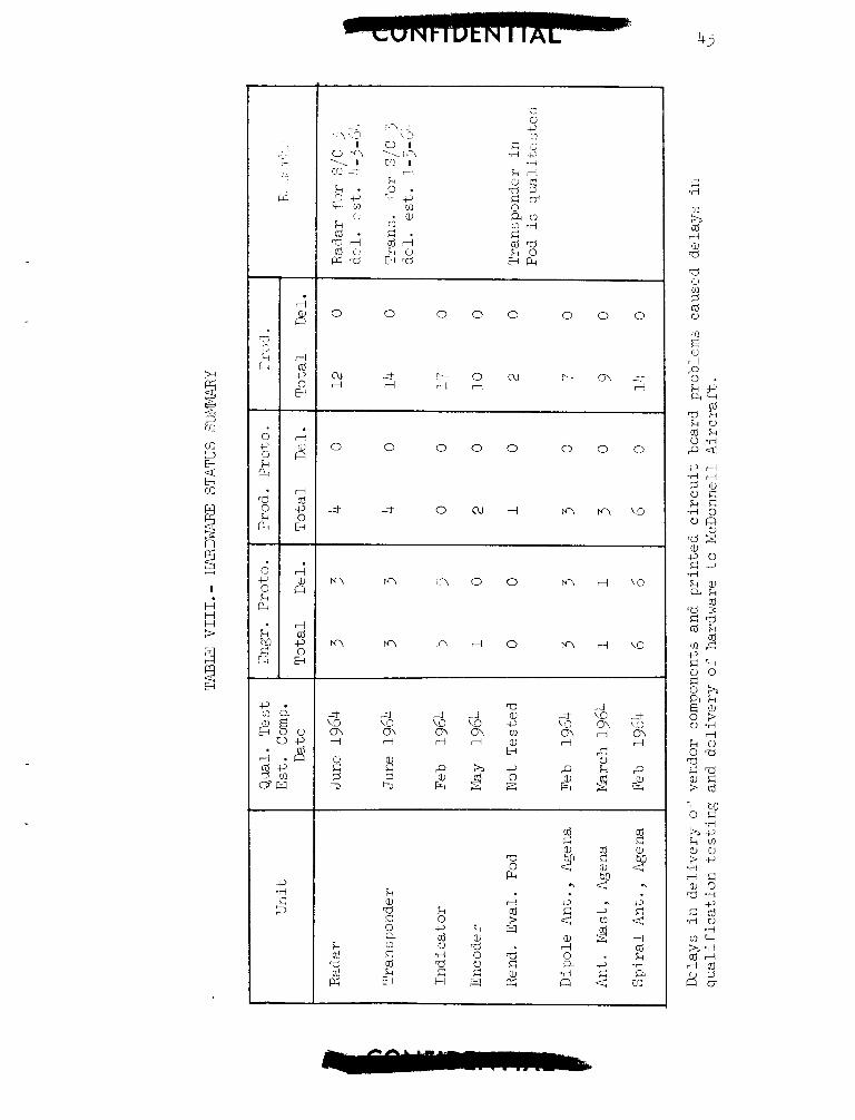
c,. m a a , E
B O 5 vc,
c . a , k !.?
0 0 0 0 0 0 0 0
0 0 0 0 0 0 0 0
M M .? 0 0 M ri \o
k 0 c, z .d 0 G H
k 5
0 0 d w
44 s One of the main reasons f o r t h e de lay i n testing i s the manufacture
of t h e new egress k i t . t he completion o f t h e f i r s t set of k i t s more than one month behind schedule. Sled development t e s t s are delayed u n t i l completion of t h e f i r s t two k i t s .
Complexity i n the machining opera t ion has made
Harness Tests.- S ix t e s t s were completed on t h e parachute harness a t El Centro, Cal i forn ia . These t e s t s a r e requi red before t h e system i s jumped by l ive sub jec t s i n t h e scheduled parachute q u a l i f i c a t i o n tests. The harness w a s taken t o 150 percent of t h e des ign load with complete s a t i s f a c t o r y results.
Center of Gravi ty S h i f t . - Data reduct ion on t h e human slump t e s t s has been completed and the f i n a l r e p o r t i s being wr i t t en . Prel iminary ind ica t ions are t h a t the slump i s w e l l w i th in t h e to l e rance of t h e system.
Two f r e e - f l i g h t tes ts were completed a t Rocket Power, Inc. , i n Mesa, Arizona. The tes ts w e r e made t o confirm predic ted t r a j e c t o r i e s w i th t h e t h r u s t vec tor on the ou te r f r inges o f t h e al lowable window. The tes t s were made from ground l e v e l with no sepa ra t ion of seat-dummy combination attempted. Both t e s t s w e r e successfu l .
Bal lu te Tests.- The f i r s t human sub jec t t es t o f t h e b a l l u t e was msde a t E l Centro, Ca l i fo rn ia , on Novcxkr 22, 1963. The j m p r l e f t t he a i r c r a f t with the predeployed b a l l u t e a t a pressure a l t i t u d e of 12,500 feet , and a t an ind ica ted a i r speed o f 110 knots. The jumper w a s programed f o r a f r ee f a l l or' 30 seconds, b u t r e l eased t h e b a l l u t e prematurely a r t e r 15-15 seconds when he experienced moderate s p i n c h a r a c t e r i s t i c s (maximum rate 50 rpm). The program i s scheduled f o r completion by t h e end of December 1963.
CREW STATION INTEGRATION
The design e f f o r t by McDonnell A i r c r a f t Corporation was completed
Many of these on e s s e n t i a l l y a l l the crew s t a t i o n reques t f o r a l t e r a t i o n s (RFA's) generated i n t h e mock-up reviews of June and July 1963. modif icat ions have been r e l eased f o r production. The remzining items a r e being incorporated i n t o the Gemini engineer ing mock-up f o r a s t ronau t eva lua t ion i n mid-December 1963.
The most s i g n i f i c a n t problem i s the bas i c crew s t a t i o n design, a t t h i s t i m e , i s t he l ack of stowage space f o r a d d i t i o n a l equipment on long dura t ion missions. A prel iminary review of t h e experimental equipmeat, which has been proposed ''3r use on the long du ra t ion f l i g h t s , i n d i c a t e s
45
t h e d e s i r e f o r several l a r g e items t o be c a r r i e d i n the cockpi t . There i s no cockpi t space a v a i l a b l e fo r stowing these l a r g e i tems on the f l i g h t s which r equ i r e s u b s t a n t i a l q u a n t i t i e s of food. Modif icat ions t o e x i s t i n g stowage provis ions are being considered. Unless t h e y are found t o be feasible, accommodation of l a r g e i tems of experimental equipment i n t h e cockpi t w i l l be impossible f o r t he longer missions.
A docking s imulat ion program vas conducted i n the Langley Research Center t e l e v i s i o n docking simulator i n September 1963 t o evaluate the Gemini docking con t ro l s and displays. The a t t i t u d e hand c o n t r o l l e r , t h e f l i g h t d i r e c t o r and a t t i t u d e ind ica to r , and t h e range/range ra te i n d i c a t o r were found t o be s a t i s f a c t o r y f o r the approach and docking maneuver. However, t he t r a n s l a t i o n a l hand con t ro l was unsa t i s f ac to ry because of e r r a t i c con t ro l slop. McDonnell A i r c r a f t Corporation has designed a new t r a n s l a t i o n a l hand con t ro l which w i l l be evaluated i n t h e t r a n s l a t i o n and docking t r a i n e r as w e l l as i n a later phase of t he Langley Research Center docking s imulat ion program. Gemini spacecraf t wi th t h e Agena t a r g e t was found t o be w e l l w i th in t h e c a p a b i l i t i e s of t h e as t ronauts f o r simulated day l igh t docking. dark-s ide docking, alinement w a s more d i f f i c u l t because of t h e l a c k of visual alinement cues. Langley Research Center has developed several l i g h t i n g a i d s f o r use as v i s u a l re ferences during t h e docking maneuver, and these l i g h t i n g a i d s w i l l be evaluated i n subsequent phases of t h e Langley Research Center program.
Alinement o f t h e
For
McDonnell A i r c r a f t Corporation and t h e F l i g h t C r e w Support Divis ion have conducted s tud ie s t o determine the adequacy of t h e out-the-window view of t h e horizon as an a t t i t u d e reference f o r r een t ry . The r e s u l t s t o da te ind ica t e t h a t t he v i e w of t h e horizon does provide an adequate re ference f o r con t ro l l i ng spacecraf t a t t i t u d e during normal and abor t r e e n t r i e s . This use o f t h e out-the-window visual reference procedure would be necessary i n case of fa i lure o f t h e i n e r t i a l measuring u n i t i n f l i g h t . Center and a t McDonnell A i r c r a f t Corporation t o determine how a c c u r a t e l y t h e a s t ronau t can con t ro l r een t ry a t t i t u d e by visual reference t o t h e horizon. These s imulat ions w i l l a l s o include eva lua t ion of window markings for a t t i t u d e reference and eva lua t ion of the e r r o r s i n the poin t o f touchdown when using horizon viewing f o r r e e n t r y a t t i t u d e con t ro l . These s imulat ions are scheduled t o commence i n December 1963.
Simulation programs a r e being e s t ab l i shed a t Ames Research
The f i r s t d r a f t of t he Gemini F l i g h t Operations Handbook has been publ ished by MSC and i s now being reviewed. The f i r s t sec t ion , which c o n s i s t s of system desc r ip t ions and schematic diagrams, w a s completed by t h e F l i g h t Operations Divis ion i n October 1963. which c o n s i s t s of opera t ing procedures and check l i s t s , was completed by t h e F l i g h t C r e w Support Divis ion i n e a r l y November 1963. A i r c r a f t Corporation i s providing t e c h n i c a l da t a and support t o these
The second sec t ion ,
McDonnell
46 I 1
. 4 .
two d iv i s ions who a r e coordinating t h e handbook as an MSC publ icat ion. The same handbook is intended f o r use by the f l i g h t c o n t r o l l e r s and the f l i g h t crew as t h e primary reference document on t h e Gemini spacecraf t .
EXTRAVEHICWAR OFERATIONS
Requests f o r proposals on the Gemini ex t r aveh icu la r l i f e support package were sen t out i n October 1963. The system being contemplated includes a high-pressure gaseous oxygen supply b o t t l e plus su i t ab le r egu la to r s and valves f o r con t ro l of t h e oxygen flow, which i s an open loop. i n i t i a l ex t ravehicu lar operat ions using a hard l ine t e t h e r and l i m i t i n g outs ide operat ions t o 10-15 minutes. November 25, 1963, and t h e eva lua t ion should be completed i n December
This system w i l l provide t h e necessary l i f e support f o r t he
The proposals were received on
1963
WATER SYSTEM
Redesign of t h e dr inking water nozzle by t h e Whirlpool Corporation has r e su l t ed i n a p i s to l - type water dispenser. dispenser has shown it t o be much easier t o handle and operate than t h e previous design. A l l operat ions can now be accomplished wi th a s ingle hand. The spacecraf t mounting provis ions for t h e water dispenser were being f ina l i zed a t t he close of t h i s r epor t ing period.
Evaluat ion of the p i s t o l
URINE SYSTElM
The design e f f o r t s t o ob ta in a new urine t r anspor t system have been only p a r t i a l l y successful t o date . pursuing t w o system concepts: one employing s t a t i c pressure d i f f e r e n t i a l and the other employing a cen t r i fuga l pump. remains unsolved i s the e l imina t ion of oxygen which becomes entrapped i n the system. The present spacecraf t i n t e r f a c e w i l l not permit oxygen f l o w i n t o the evaporator. engineer a t McDonnell A i rc ra f t Corporation t o f a c i l i t a t e i n t e r f a c e co- ord ina t ion unt i l t h e present problems are resolved. McDonnell Ai rcraf t Corporation has been d i r ec t ed t o i n i t i a t e a backup e f f o r t t o develop a n a l t e r n a t e ur ine c o l l e c t i o n and d i sposa l system. The Crew Systems Divis ion i s a l s o reviewing t h e Mercury MA-9 urine system as a bas i s f o r possible f u r t h e r development and app l i ca t ion t o the Gemini spacecraf't .
Whirlpool Corporation has been
The primary problem which
Whirlpool Corporation i s s t a t i o n i n g a r e s iden t
I n addi t ion ,
47
Whirlpool Corporation i s p resen t ly f a b r i c a t i n g working prototypes of t h e i r two system concepts, which now appear f eas ib l e . hardwaE i s scheduled f o r de l ivery t o MSC f o r eva lua t ion by mid-December 1963. Production r e l ease i s being withheld pending a s a t i s f a c t o r y system demonstration.
The prototype
COMMUNICATIONS SYSTEM
Voice Communications
Design approval t e s t s are complete for t he voice c o n t r o l cen te r (VCC) and t h e t ransmi t te r - rece iver (T/R) u n i t s except f o r t h e ove r s t r e s s t es t s on the UHF T/R which are now scheduled for January 1964. de lay w a s because of t he replacement of a temperature s e n s i t i v e feed- through capac i tor which caused low power output. No o the r developmental problems remain and d e l i v e r i e s should proceed according t o schedule. The T/R cases a r e t o be gold plated for heat t r a n s f e r purposes.
The
A vendor has been se l ec t ed and design i s v i r t u a l l y complete for t h e a s t r o n a u t ' s l i g h t weight headset. This i t e m i s stowed i n a pocket on t h e l e g of t h e suit and plugs i n t o a quick disconnect plug near the neck ring where t h e helmet is removed. approval during December 1963.
Prototypes a r e expected for
Hardware d e l i v e r y s t a t u s i s shown i n t a b l e s I X and X.
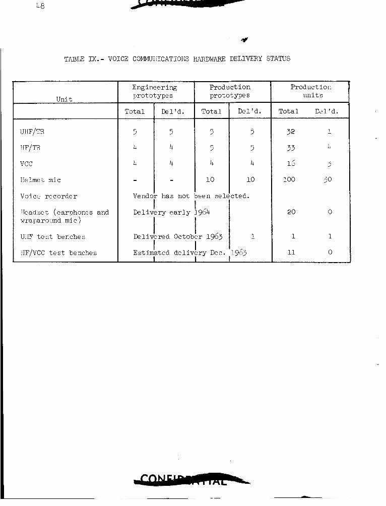
48
TABU M.- VOICE COMMliiiICATIOlIS HARDWARE DELIVERY STATUS
Unit
UHF/TR
IfF/TR
vcc
Helmet mic
Voice recorder
Headset (earphones and wraparound mic)
UIIF t e s t benches
IfF/VCC t e s t benches
Engineering pro t o t ype s
Delivery e a r l y
Product i o n prototype s
To ta l
5
5
4
10
een sel
954
I I
I Delivered October 1963
Estimated d e l i v e r y Dec. 1 *
Del 'd .
5
5
4
10
:ted.
1
-963
Product ion u n i t s
Tota l Dc,l'd.
32 1
33 I!
1; 3
100 50
20 0
1 1
11 0
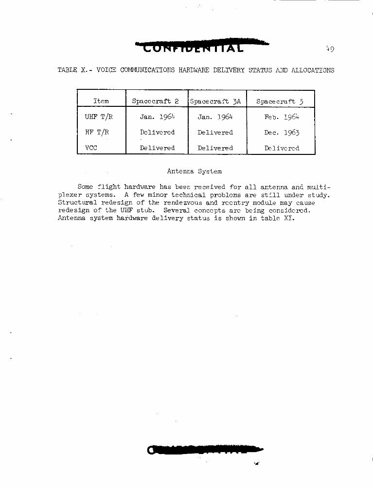
T.4BLF: X.- VOICE COMMUNICATIONS HARDWARE DELIVERY STATUS AND ALLOCATIONS
I t e m
UHF T/R
HF T/R
vcc
1 I I I 1 Spacecraf t 2 Spacecraf t 3A Spacecraf t 3
Jan. 1964 Jan. 1964 Feb. 1964
Delivered De 1 ive r e d Dec. 1963
De l i v e red De l i v e red De 1 ive red
Antenna System
Some f l i g h t hardware has been received f o r a l l antenna and m u l t i - p lexer systems. A few minor t echn ica l problems a r e s t i l l under study. S t r u c t u r a l redesign of the rendezvous and r e e n t r y module may cause redesign of the UKF stub. Several concepts are? being considered. Antenna system hardware d e l i v e r y s t a t u s i s shown i n t a b l e X I .
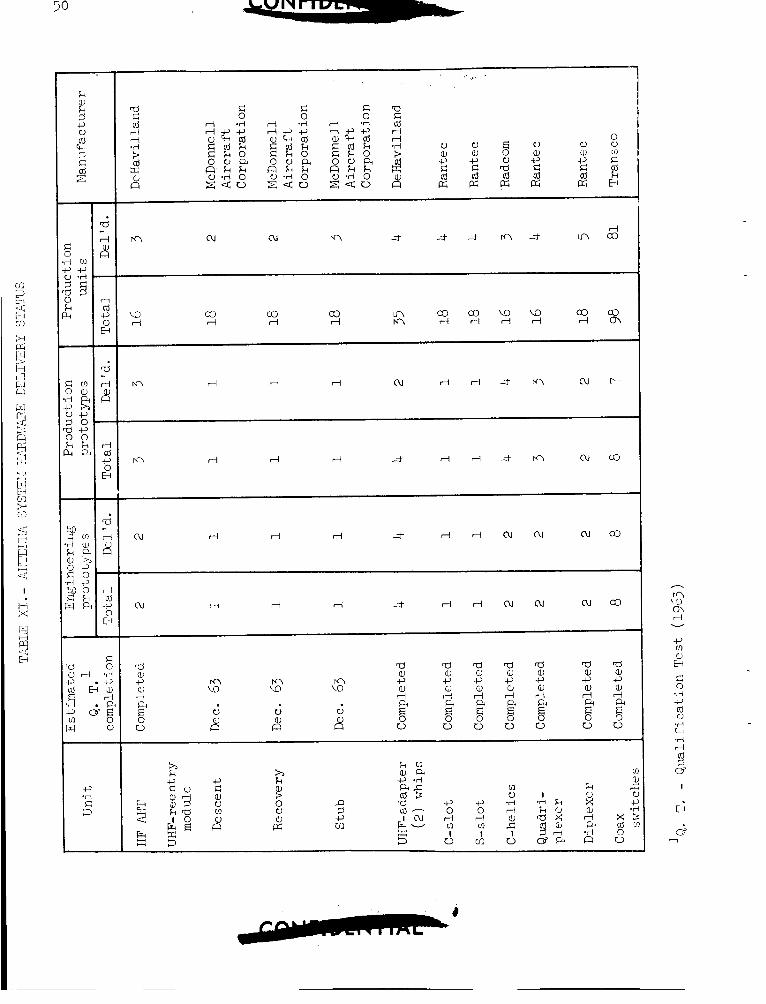
50
m
V a, c, E: Ld ffi
V aJ c, Ll Ld ffi
E 0 V a Ld ffi
V aJ c, G Ld ffi
0 d c, d cb ffi
Time Reference System
Scheduled hardware d e l i v e r i e s were delayed by several f a i l u r e s of It w a s a r e s i s t o r used ex tens ive ly i n the e l e c t r o n i c and event t i m e r .
judged necessary t o replace t h i s metal film r e s i s t o r with a high- r e l i a b i l i t y component from a d i f f e r e n t suppl ie r . The de lay w a s because of t he shor t supply of t h e new r e s i s t o r , r e t r o f i t t i n g of some modules, and r equa l i f i ca t ion . Other qua l i t y con t ro l problems have caused minor delays. Table X I 1 summarizes the hardware status.
Estimated hardware de l ivery d a t e s are shown i n Table XIII.
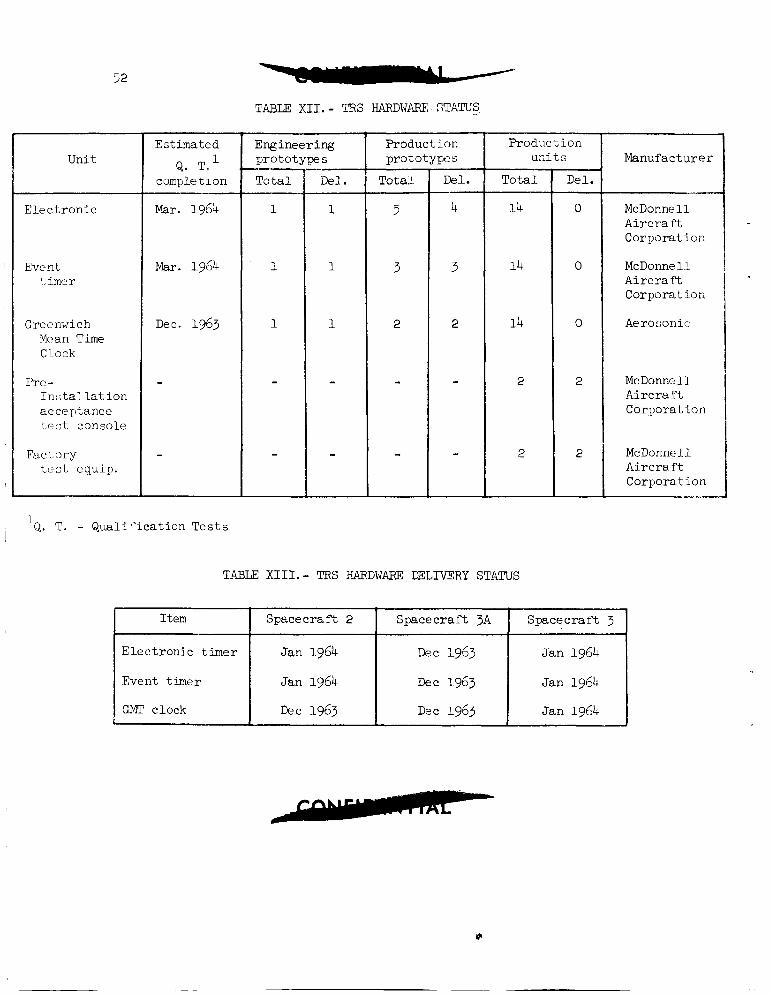
52
Item
E lec t ron ic timer
Event timer
GMT clock
TABLE: X I I . - TRS HARDWARF: STATUS,
Spacecraf t 2 Spacecraf t 3A Spacecraf t 3
Jan 1964 Dec 1963 Jan 1964
Jan 1964 Dec 1963 Jan 1964
Dec 1963 Dzc 1963 Jan 1964
I Unit
E l e c t ron i c
I Event t i r n c r
Greenwich Mc7an Time Clock
Pre - 1 n : ; t a l l a t ion acceptance t e s t console
Fac Lory Lest cquip.
Est imated
Q. T.l completion
Mar. 1964
Mar. 1964
Dec. 1963
Engineering p ro to t
To ta l -I
E S -- D e l .
Froduct ion prototypes ~
Tota l Del.
Product i o n w i t s
To ta l
14
14
14
2
2
'Q. T. - Q u a l i f i c a t i o n T e s t s
TABU XII1.- TRS HARDWARE DELlVERY STATUS
- D e l .
0 -
0
0
2
2
Manufacturer
McDonnell Ai rcra t i Corporat ion
McDonnell A i r c r a f t Corpora t ion
Aerosonic
McDonne 1 1 A i r c r a f t Corporation
McDonnell A i r c r a f t Corporat ion
-.
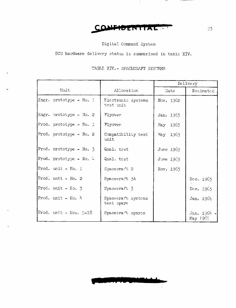
D i g i t a l Command System
DCS hardware d e l i v e r y s t a t u s i s summarized i n t a b l e XIV.
TABLE Xm.- SPACECRAFT SYSTEMS
Unit
E n g r . prototype - No. 1
Engr. prototype - No. 2
Prod. prototype - No. 1
Prod. prototype - No. 2
Prod. prototype - No. 3
Prod. prototype - No. 4
Prod. un i t - No. 1
Prod; u n i t - No. 2
Prod. u n i t - No. 3
?rod. un i t - No. 4
?rod. un i t - Nos. 5-18
Allocat ion ~~~~
Elec t ronic systems t e s t unit
F1 yover
Flyove r
Compatibil i ty t e s t uni t
Qual. t e s t
Qual. t e s t
Spacecraft 2
Spacecrar't 3A
Spa ce c r a f t 3
Spacecraft systems t e s t spare
Spz ce e ra f t spares
Date
Nov. 1962
Jan. 1963
May 1963
May 1963
June 1963
June 1963
Nov. 1963
E s t h a t e d
Dec. 1963
Dee. 1963
Jan. 1964
Jan. 1964 - May 1965
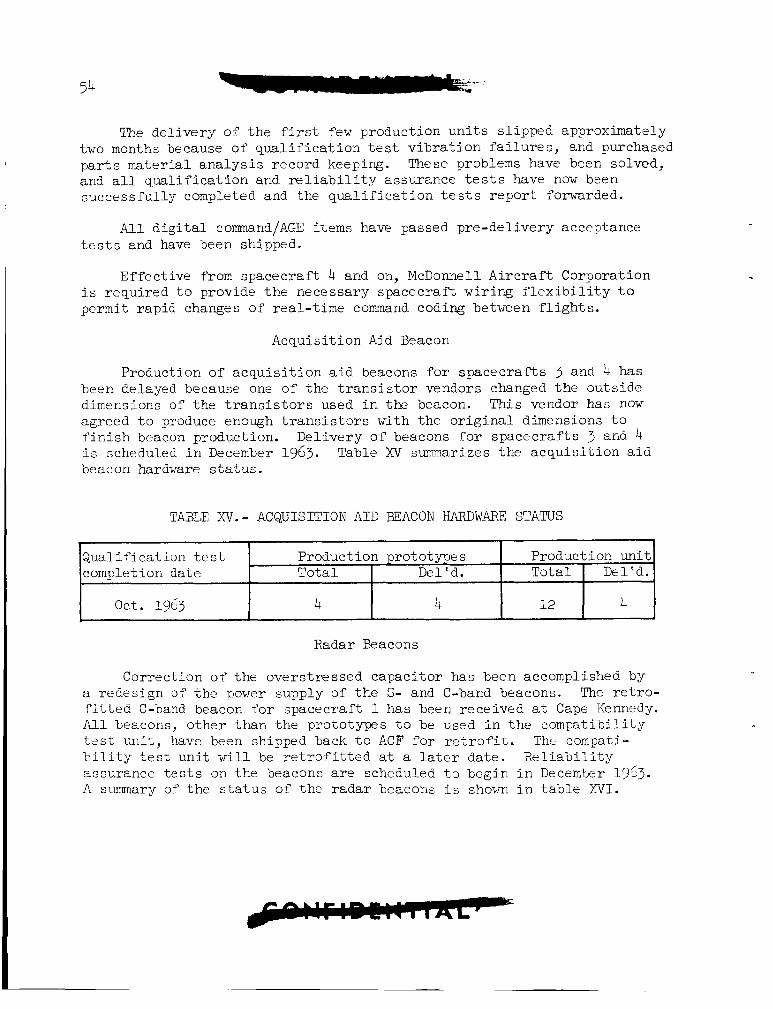
54
Q u a l i f i c a t i o n t e s t completion d a t e
oc t . 1963
The de l ive ry of t h e f i r s t f e w production u n i t s s l ipped approximately
These problems have been solved, two months because of q u a l i f i c a t i o n t e s t v i b r a t i o n f a i l u r e s , and purchased p a r t s ma te r i a l a n a l y s i s record keeping. and a l l q u a l i f i c a t i o n and r e l i a b i l i t y assurance t e s t s have now b?en successfu l ly completed and the q u a l i f i c a t i o n t e s t s r e p o r t forwarded.
Production prototypes Production u n i t T o t a l D e l ' d. To ta l Del 'd.
4 4 12 4 -
A l l d i g i t a l comand/AGE i t e m s have passed pre-de l ivery acceptance t e s t s and have been shipped.
Ef fec t ive from spacecraf t 4 and on, McDonnell A i r c r a f t Corporation i s requi red t o provide t h e necessary spacecraf t w i r i n g f l e x i b i l i t y t o permit rap id changes of real-time command coding between f l i g h t s .
Acquis i t ion Aid Beacon
Production of a c q u i s i t i o n a i d beacons f o r spacec ra f t s 3 and 4 has been delayed because one of t h e t r a n s i s t o r vendors changed t h e outs ide dimensions of t h e t r a n s i s t o r s used i n the beacon. This vendor has now agreed t o produce enough t r a n s i s t o r s with t h e o r i g i n a l dimensions t o f i n i s h beacon production. Del ivery of beacons f o r spacec ra f t s 3 and 4 i s schedilled i n December 1963. beacon hardware s t a t u s .
Table XV summarizes t h e a c q u i s i t i o n a i d
TABLE XV.- ACQUISITION A I D BEACON IIARDWARF: STATUS
Radar Beacons
Correction of t he overs t ressed capac i tor has been accomplished by a redes ign of t h e power supply of t h e S- and C-band beacons. The r e t r o - f i t t e d C-band beacon f o r spacecraf t 1 has been rece ived a t Cape Kennedy. A l l beacons, o the r than t h e prototypes t o be used i n t h e compa t ib i l i t y t e s t un i t , have been shipped back t o ACF f o r r e t r o f i t . ThL compati- b i l i t y t e s t u n i t w i l l be r e t r o f i t t e d a t a l a t e r da te . R e l i a b i l i t y assurance t e s t s on the beacons a r e scheduled t o begin i n December 1953. A summary of t he s t a t u s of t he radar beacons i s shown i n t a b l e WI.
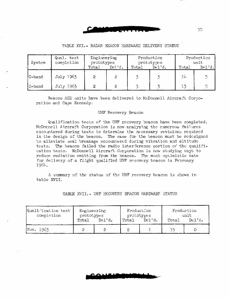
55
System
C-band
S-band
T-4BLE XVI.- F4DAR BEACON HARDWARE DELIVERY STATUS
Qual. t e s t Engineering Production Product i on completion prototype s prototypes u n i t
. Tota l Del'd. . Tota l I k l ' d . . Tota l Del 'd.
J d Y 1963 2 2 3 3 14 5
J u l y 1963 2 2 3 3 13 5
Q u a l i t ' i c a t i on tes t Eng ines r i n g completion prototypes
To ta l Del'd.
Beacon AGE u n i t s have been de l ivered t o McDonnell A i r c r a f t Corpo- r a t i o n and Cape Kennedy.
Production Production pra to types u n i t
T o t a l Del'd. To ta l Del'd.
UHF Recovery Beacon
Nov. 1963
Q u a l i f i c a t i o n tes ts of t h e UHF' recovery beacon have been completed. McDonnell A i r c r a f t Corporation i s now analyzing t h e numerous failures encountered dur ing tes ts t o determine t h e necessary r ev i s ions requi red i n t h e design of t he beacon. The case for t h e beacon must be redesigned t o a l leviate seal breakage encountered during v i b r a t i o n and a l t i t u d e tes ts . The beacon f a i l e d t h e r ad io in t e r f e rence po r t ion of t h e q u a l i f i - c a t i o n tests. reduce r a d i a t i o n emi t t i ng from the beacon. for d e l i v e r y o f a f l i g h t q u a l i f i e d UHF recovery beacon i s February
McDonnell AircrarY. Corporation i s now s tudy i rg ways t o The most o p t i m i s t i c da t e
1964.
I 2 1 0 15 2 2
A s m s r y of the s t a t u s o f the UHF recovery beacon i s shown i n table XVII.
TABLF: XVI1.- UHF E C O V E R Y BEACON HARDWARE STATUS
INSTRIJMENTATION SYSTEM
Deliveries of the pulse-code modulation system built by Electro- Mechanical Research have slipped because of recurring problems in the in-house test set; low-level accuracy not within specification limit of k2 bits error, and a NASA requirement to X-ray all flight system transis- tors. Electro-Mechanical Research has been able to correct most of the in-house test set problems by design changes and more prudent routing and shielding of cables. A plan of parallel efforts has produced better selective shielding in the programer wiring matrix, an improved low- level amplifier clamp, and a constant current source for the low-level amplifier. fication control drawing parts and not be allowed to fly, NASA felt that further efforts to reduce the error in these systems would not be fruitful. McDonnell Aircraft Corporation was directed to accept sys- $erns 4, 5, and 6 with 95 percent of the low-level data channels within *6 bits error and the remaining 5 percent of the channels to be within +8 bits error. Systems 4, 5, and 6 are now scheduled for delivery to McDonnell Aircraft Corporation in December 1963. instrumentation system equipment is given in table XVIII.
Since all systems built up to system 6 will have non-speci-
Delivery status of all
The Gemini PCMtape recorder built by RCA successfully passed the sinusoidal vibration specification after the following design modifi- cations were made:
1.
2.
3.
4.
5.
6.
7.
8.
9.
10.
Vibration isolation by means of ball joint suspension
Modified cover and case
Laminated motor board (laminating modified from earlier methods)
Dual capstan tape drive system
Modified tape path
Moving pressure belt
New tuning fork
Optimization of bearing loading reels, converters, rollers, etc.
Modification of speed converter
Increased shaft sizes in drive mechanism
57
11. New d e t e c t i o n system employing t h e one-shot mul t iv ib ra to r
12. Brass counterweight added i n area of record/reproduce heads ( t o dampen v i b r a t i o n e f f e c t s )
Many of t hese fixes had been t r i e d back i n June 1963, b u t optimiza- t i o n of t hese and t h e add i t iona l changes were needed. t i o n a l mechanical-type f i x e s reduce t h e b i t j i t t e r so much t h a t 10 percent b i t j i t t e r w i l l never occur and ground s t a t i o n s w i l l have no d i f f i c u l t y i n remaining locked on, t h e "single-shot" playback d e t e c t i o n scheme can be used. The use of t h e "single-shot" mul t iv ibra tor - type of d e t e c t i o n system allows b i t j i t t e r i n excess of t h a t permitted by t h e prev ious ly used phase-locked o s c i l l a t o r (PLO) de t ec t ion system, and. guarantees no data dropouts s ince d e t e c t i o n i s on a b i t -by-b i t basis.
Since t h e addi-
The RCA b u i l t t e lemet ry t r ansmi t t e r s fa i led during t h e v i b r a t i o n t e s t po r t ion of t h e q u a l i f i c a t i o n tests. t h e q u a l i f i c a t i o n - t e s t v ib ra t ion por t ion .
Three failures occurred dur ing These were:
1. A t r a n s i s t o r fa i lure which w a s found t o be the result of poor t r a n s i s t o r f a b r i c a t i o n (not i n v i b r a t i o n s e n s i t i v e area).
2. A trimmer capac i to r whose fa i lure cannot p o s i t i v e l y be a t t r i b - uted t o v ib ra t ion , s ince it i s on t h e f r i n g e of t h e v i b r a t i o n s e n s i t i v e area.
5. A fixed capac i to r l e a d w a s broken by v ib ra t ion .
With t h e occurrence of these problems, RCA mapped t h e e n t i r e t r a n s - m i t t e r f o r v i b r a t i o n s e n s i t i v e areas and no o the r s were found t o exist. There has been a major redesign of t h e production prototype t r a n s m i t t e r s t o enable them t o withstand a thermal surge without ou t -of -spec i f ica t ion performance. many areas in . t h e t r a n s m i t t e r so t h a t they are v i b r a t i o n s t i f f e n e d . t h e t h r e e t r a n s m i t t e r s i n spacecraf t 1 are engineer ing models not having these strengthened areas , a very good chance e x i s t s f o r v i b r a t i o n pro- blems t o occur i n the engineer ing mociels.
Addit ional sh ie ld ing baffles were added which s t rengthen Since
The approach taken by RCA has been t o s e l e c t i v - l y foam pot areas watching f o r d i e l e c t r i c and performance lo s ses .
RCA recommended a combination o f f o m po t t ing and the add i t ion o f m e t a l l i c s tuds fastened t o the cover t o dampen t h e v i b r a t i o n z t n s i t i v t "X12'" board t o the e f f e c t s o f v ibra t ion . R e t r o f i t o f thi? nine produc- t i o n prototypes t r a n s m i t t e r s w i l l be complete on December 23, 1963, an6 q u a l i f i c a t i o n t e s t s will then resume. Ths first t h r e e r e t r o f i t t e d t r a n , - m i t t e r s a r e due thd r i r s t v e ~ k 511 Decembzr 1963 znd vi11 bE cent t o
4
58
spacecraf t 1 a t Cape Kennedy. t e s t s have not been run:
1. Vibrat ion
2. Shock
3. Accelerat ion
4. Acoustic noise
5. S a l t water immersion
6. Humidity
The following q u a l i f i c a t i o n t e s t s had been completed bu t must now be re-examined as t o t h e i r v a l i d i t y with t h e r e t r o f i t t e d t r ansmi t t e r s :
I n q u a l i f i c a t i o n t e s t i n g the following
1. Alti tude-temperature endurance
2. High temperature
3. Low temperature
4. Thermal surge
5. Radio frequency in t e r f e rence
The f i n a l t h r e e equipment racks f o r t h e -1 PCM t e lemet ry ground checkout s t a t i o n were received by McDonnell A i r c r a f t Corporation i n November 1963. -3 s t a t i o n a re being cor rec ted by t h e Control Data Corp., and acceptance of t h i s s t a t i o n i s expected t o commence on December 9, 1963.
Problems which have a r i s e n i n t h e CDC p r i n t e r f o r t h e
Delivery of t h e f i r s t PCM tes t set has s l i pped u n t i l Apr i l 1, 1964. This s l i p has r e s u l t e d from t he necess i ty of incorpora t ing "cross-bar switching" i n order t o reduce vol tage drops ac ross switch contac ts and l i n e noise e f f e c t s t o l e s s than 70 microvol ts .
The e a r l y in s t runen ta t ion e q u i p - n t d e l i v e r y s t a t u s i s given i n t a b l e XVIII. date i s shown.
Equipment has e i t h e r been received or the expected de l ive ry
I
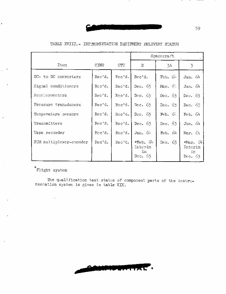
59
TABU XVIII. - INSTRUMENTATION EQUIPMENT DELIVERY STATUS
I t e m
DC- t o DC conver te rs
S igna l condi t ioners
Accelerometers
Pressure t ransducers
Temperat we sensors
Transmit t e r s
Tape recorder
PC'M mu1 t i plexer-encoder
* F l i g h t sys tern
ClMU
Rec Id.
Rec'd.
Rec'd.
Rec'd.
Rec 'd.
Rec'd.
Rec'd.
Rec'd.
C T U ~
Rec'd.
Rec'd.
Rec'd.
Rec'd.
Rec'd.
Rec'd.
Rec 'd.
Rec'd.
Space c ra ft
2
Rec'd.
Dec. 63
DW. 63
D ~ C . 63
Dec. 63
D ~ C . 63
Jan. 64
*Feb. 64 In t c r im
i n Dee. 63
3A
Feb. 64
Mar. 64
Dec. 63
Dec. 63
Feb. 64
Dec. 63
Feb. 64
Dec. 63
3
Jan. 64
Jan. 64
Dec. 63
Dec. 63
Feb. 64
Jan. 64
Mar. 64
+Mar. 64 In t e r im
i n Dec. 63
The q u a l i f i c a t i o n t e s t s t a t u s of component p a r t s of t h e in s t ru - mentation system i s given i n t ab le X I X .
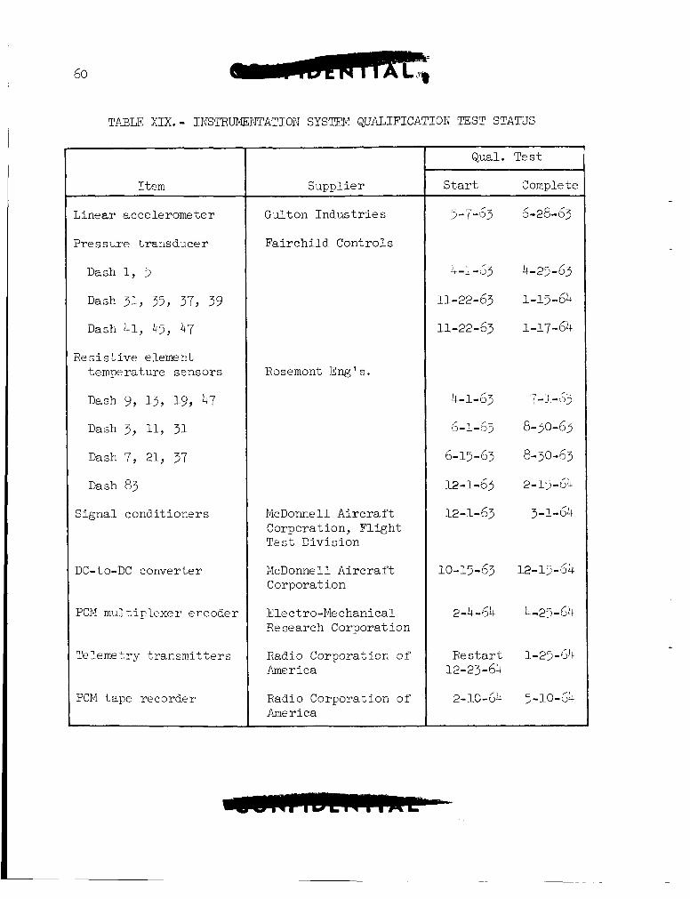
60
TABLE XIX. - INSTRUMENTATION SYS'ITM QUALIFICATION TEST STATUS
Item
Linear accelerometer
Pressure t ransducer
Dash 1, 5
Dash 31, 35, 37, 39
Dash 41, 45, 47
Res is t ive element temperature sensors
Dash 9, 13, 19, 47
Dash 3, 11, 31
Dash 7, 21, 37
Dash 83
Signal condi t ioners
D C - t o - DC c o nve r t e r
PCM mul t ip lexer encoder
Telemetry t r ansmi t t e r s
PCM t ape recorder
Gulton I n d u s t r i e s
Fa i r ch i ld Controls
Rosemont Erg ' s .
McDonnell A i r c r a f t Corporation, F l i g h t Te s t Divis ion
McDonnell A i r c r a f t Corporation
E l e c t r o -Me c han i c a l R e search Corporation
Radio Corporation of' America
Radio Corporation o f America
Qual. Tes t
S t a r t Complete
3-7-53 6-28-53
4-1-53 4-25-63
11- 22- 63 1-15 - 64 11-22-63 1-17-64
4-1-63 7-1-63
6-1-67 8-30-63
6-15-63 8-30-63
12-1-63 2-1>-6$
12-1-63 3-1-64
10-15-63 12-13-64
2-4-61; 4-25-64
R e start 1-25-64 12-23-6:
61
Astronaut Instrumentation
Evaluation of all prototype hardware, with the exception of the impedance pneumograph, has been completed. The results of this evalu- ation indicate the following changes are needed for flight hardware:
1. The output resistance of the blood pressure measuring system signal conditioner must be reduced from 5000 ohms to 1000 ohms.
2. The tape recorder recording time must be increased from 25 hours to a minimum of 72 hours because of the inflight changing of tape being so impractical.
Specifications are being prepared for flight hardware bioinstrumen- tation. ment of a qualification test program for components located inside the pressure suit. harnesses is scheduled for June 1964.
Release of the specifications has been delayed awaiting develop-
Delivery of completed flight hardware bioinstrumentation
POWER SuPPLlES
Fuel Cells
The initial eight stacks produced by General Electric have met acceptance standards. However, subsequent production has failed to yield any additional satisfactory stacks. Lntensive investigation to determine the cause of poor performance of the production stacks. is being delayed until the cause of the poor performance is determined.
The vendor is conducting an
The assembly of any additional production stacks
The eight stacks were assembled (together with one "preproduction" stack) into three test sections. in McDonnell Aircraft Corporation power systems tests. The performance of these two stacks has dropped to almost minimum specification require- ments in the initial 25 hours of testing. The third section has failed to meet pre-delivery acceptance requirements.
Two of these sections are being used
Preliminary studies indicate that purge-gas flow requirements can be met by the existing regulators. be added for redundancy purposes. McDonnell Aircraft Corporation is also studying the feasibility of providing lower temperature coolant to the fuel cell. Tests of single cells show an approximate doubling in fuel cell life with a 20° F. lowering of the operatir,g temperature.
However, 8n additional regulator ma.y
62
The vendor is also investigating a redesign of the hydrogen side of the cells to previae positive purging of inerts and water. Design features under investigation include removal of the hydrogen side wicks; inclusion of purge tube restrictors so that a uniform pressure drop can be achieved which will forct. water out of the tube; and dams to direct the flow of the hydrogen across the cell. containing these design modifications has accumulated more than 600 hours of within-specification operation, while utilizing coolant at a. reduced temperature. "Wet proofing" of the cell with Teflon will also be tested to determine whether loss of the membrane active material can be reduced.
The first buildup
Incorporation of the aforementioned coolant system and fuel cell design modifications on initial spacecraft systems appears unlikely. However, these modifications wi l l probably be made on later spacecraft to achieve the two-week mission requirements.
Studies have been initiated to reduce the preflight testing of fuel cells to achieve increased useful mission life.
The contract for analysis of fuel cell product water chemical and bacteria content has been placed with Ionics, Inc. of Cambridge, Masss- chusetts. However, testing has been delayed because of the lack of suitable production fuel cells.
Tests of the monitoring control unit (MCU) have shown it to meet basic specification requirements. However, the poor load sharing of stacks experienced thus far indicates that the MCU wi l l not be able to determine the adequacy of fuel cell performance. MCU program has been terminated.
All activity on the
Batteries
After reconsidering the specifications and tolerances on the titanium cases used in the batteries, McDonnell Aircraft Corporation directed Eagle-Picher to relax specific tolerances and welding specifi- cations where it was legitimate to do so. With cases already fabricated, Eagle-Picher has delivered batteries to Cape Kennedy in support of space- craft 1.
The spacecraft -7 and -9 main bus and squib batteries successfully completed all prequalification tests.
63
AERODYNAMIC TESTING
The following two aerodynamic t e s t s were conducted during the repor t ing period.
Transonic Buffet Tes ts of Gemini-Titan I1 - The purpose of t h i s t e s t was t o i n v e s t i g a t e t h e loads introduced i n t o t h e Gemini Launch vehic le s t r u c t u r e due t o aerodynamic bu f fe t . The t e s t w a s conducted i n September 1963 i n the Ames Research Cen te r ' s 14 - f t . t r anson ic wind tunnel . The Mach range inves t iga ted w a s from 0.6 through 1.14 a t ar@es of a t t a c k of 0, 4, and 8 degrees. i n d i c a t e t h a t t h e loads due t o b u f f e t a r e no t , excessive. However, s ince the v a r i a t i o n of t hese loads with Mach number w a s not zdequately i n v e s t i - ga ted due t o wind tunnel l imi t a t ions , f u r t h e r t e s t i n g a t higher Mach numbers i s required. Planning i s i n progress t o conduct f u r t h e r tests i n January 1964 t o extend t h e b u f f e t i n v e s t i g a t i o n Mach number range through the m a x i m u m dynamic pressure region.
Prel iminary a n a l y s i s of t h e data
Fu l l - sca l e Pa rag l ide r T e s t - The purposes of t h i s t e s t were t o determine t h e aerodynamic c h a r a c t e r i s t i c s of t h e f u l l - s c a l e wing, de f ine t h e l i n e r igg ing requi red f o r tow-test veh ic l e (TTV) f l i g h t , eva lua te t h e ef'fect of s t r u c t u r a l de f l ec t ions on the aerodynamic c h a r a c t e r i s t i c s , and de f ine the "qa" boundary f o r spreader-bar buckling. The tes t w2.s conducted i n October 1963 i n the Ames Research Cen te r ' s $0 x 80-f t . wind tunnel .
I n i t i a l data f r o m t h e computer i nd ica t ed t h a t kee l de f l ec t ions were causing extreme e f f e c t s on t h e bas i c aerodynamics as determined from the ha l f - sca l e wind tunnel r e s u l t s , and t h a t t r i m po in t s could not be estab- l i s h e d with the r igg ing used. Consequently, i nves t iga t ions of w i n g r igg ing not prev ious ly included i n t he t e s t p lan were i n s t i t u t e d . Af te r completion of t he tes t , e r r o r s i n the d a t a reduct ion equat ions were discovered and when corrected, t he i n i t i a l results were negated. However, 3 s a r e s u l t of t he a d d i t i o n a l t e s t i n g , i n s u f f i c i e n t da t a were obtained t o def ine t h e l i n e r igg ing f o r TTV f l i g h t and t o s a t i s f y a l l t he t e s t objec t ives . Consequently, a repeat t e s t has been scheduled t o begin December 3, 1963, t o obta in the da t a required.
LAUNCH AM) TARGET VEHICLES INTEGRATION
GEMINI LAUNCH VEHICLE (GLV)
GLV Schedule Review. - Schedule reviews were he ld t o e s t a b l i s h schedules and ground r u l e s for t he f i r s t t h r e e Gemini lau-nch veh ic l e s
64
and spacecraf t . Tenta t ive schedules were e s t a b l i s h e d based on the following ground r u l e s : No f l i g h t readiness f i r i n g (FRF) on GLV 1, 2, and 3; sequenced compa t ib i l i t y f i r i n g (SCF) on a l l t h r e e vehic les ; extended e l e c t r i c a l e l e c t r o n i c in t e r f e rence (EEI) t e s t s on GLV 1 and 2 b u t not on 3; and POGO f i x e s t o be on all t h r e e vehic les . assembly removal t i m e not included.
Turbopump
Dates f o r GLV on the pad, SCF, spacecraf t on t h e pad, and launch are being e s t ab l i shed and w i l l be discussed f u r t h e r a t a schedule review meeting on December 13, 1963.
Weight.- A spacec ra f t weight p l o t t e d aga ins t launch payload capa- b i l i t y comparison i n d i c a t e s t h a t t he GLV w i l l be capable of launching t h e f i r s t nine spacecraf t . For missions 10 through 12, i f a paragl ider i s used, a launch c a p a b i l i t y d e f i c i t of over 400 pounds i s indicated. The 220-pound payload increase by GLV weight reduct ion i s being formalized by Space Systems Divis ion on a c o s t b a s i s and will be implemented i n t h e near fu ture .
Longitudinal (POGO) Vibra t ion S ta tus . - Considerable progress w a s
This
The N-25 w a s t h e f i r s t vehic le
i nd ica t ed i n e l imina t ing objec t ionable long i tud ina l o s c i l l a t i o n s . lowest l ong i tud ina l v i b r a t i o n recorded t o d a t e w a s on t h e N-23. v i b r a t i o n amounted t o *O.llg a t a frequency of 13.2 cps a t a s t a t i o n equivalent t o t h e spacecraf t s t a t i o n . t o have f u e l accumulators i n s t a l l e d i n add i t ion t o t h e ox id ize r stand- pipe.
The
This same conf igura t ion i s planned f o r t h e N-29 f l i g h t .
Propulsion System Development.- Qu i t e an ex tens ive and d e t a i l e d design review i s being conducted a t Aerojet-General Corp., and a t Martin Company t o improve t h e r e l i a b i l i t y of t h e var ious engine components and the o v e r a l l performance of t h e power p l an t .
Propel lan t Tank Level Sensors.- EEI problems have been occurr ing wi th the Ti tan I1 Powertron sensors . Also erroneous s i g n a l s have been experienced during T i t a n I1 f l i g h t . t he GLV ex i s t :
Three p o s s i b i l i t i e s f o r a f i x on
1. Use t h e improved Powertron sensor f o r ins t rumenta t ion purposes only.
2. Use the Bendix sensor which i s being reviewed by Space Systems Divi s ion/Aerospace .
j. Eliminate t h e shutdown por t ion of t h e sensor o r t h e e n t i r e low- l e v e l sensor znd 3llow shutdown t o occur by f u e l o r ox id i ze r deplet ion. The shutdown f e a t u r e on t h e sensors has been e l imina ted on T i t a n I1 s ince the s i x t h f l i g h t . Fuel deple t ion shutdcwns have occurred orL
N-14, N-19, N-24, PI-25, and N-27 without difficulty. A GLV payload increase capability of 163 pounds can be realized by elimination of sensor shutdown capability.
Engine Preva1ves.- New prevalves are being considered for Stage I and I1 engine propellant lines effective with GLV 4 and on. These new prevalves w i l l be nitrogen gas-operated instead of squib-operated and will be capable of being turned on and off without replacing the valve. Qualification testing on the new design man-rated prevalves w i l l be re- quired. this time. An Engineering Change Proposal is being submitted to SSD on this proposal. The use of the new design prevalves w i l l result in a weight saving for the vehicle. With this configuration, only flight valves will be provided. required.
Proposals are being evaluated for the new man-rated prevalve 2t
Valves for ground use only will no longer be
The prevalves to be used on GLV 1, 2, and 3 will differ from Titan I1 prevalves in that the shearable diaphragm used on Titan 11 has been re- placed by an O-ring seal. valves after SCT and FRF without replacing the valve.
This O-ring seal will permit closing the
POGO Fuel Line Accumulator.- The accumulator design is being studied to eliminate friction and to improve its function in eliminating longitudinal oscillation in flight. A new gas-type torus-shaped accumu- lator, which is lighter in weight, is also being studied.
Second Stage Gas Generator.- The design for the second stage gas generator used on the Titan I1 has not proven satisfactory because of combustion chamber fluctuations in pressure and the possibilities of plugging of the multiple oxidizer-orifice injector 8s demonstrated on several flights. To correct this problem a single oxidizer-orifice design was used which was not satisfactory because of P fluctuations.
Corporation believes will be satisfactory. four 0.0485'' dia. orifices for oxidizer injection, which are about twice . the size of the present orifices. This arrangement is known as the Toad- stool or Oxidizer Splash Plate Design. Tests indicate that the design is 3s stable as the production design and has less chance of clogging.
A design, designated at MOD 7A has now been made, which C Aerojet-General This redesign or rework uses
Pending development of a suitable design of the gas generator, the interim policy consists of super cleaning. As a final check before launch, gas is discharged through the orifices and the pressure drop checked so accurately that one plugged orifice can be detected.
Before adoptiqn on the GLV, the MOD 7A design will be flight tested on the Titan 11.
65
Turbo Pump Gearbox.- In t h e gearbox inves t iga t ion being c a r r i e d on, t h e following s t eps a r e being taken t o increase the opera t iona l l i f e of t he assembly.
1. Resonance eva lua t ion i s being made.
2. Gear too th geometry i s being inves t iga ted .
3. Deflection c h a r a c t e r i s t i c s a r e being inves t iga ted .
4. Independent appra i sa l s are being made by G. E. and Western Gear.
S i x Stage I engine gearboxes a r e being t e s t e d t o determine t h e s u i t -
The new gear used a b i l i t y of t he redesigned gears. The i d l e r gear has a t h i c k e r web and r i m and a black oxide i s used as a p ro tec t ive coating. a modified (vinco gear type) t oo th p r o f i l e i n s t ead of a s tandard too th p r o f i l e .
After reviews a t Western Gear, f i v e of t he six gearboxes completed
Two runs have been completed on the s i x t h gearbox with the the 14 runs ( two 200 second and twelve 165 second) a t Aerojet with no d i f f i c u l t y . remaining runs scheduled f o r completion by December 7, 1963. gearboxes 7 and 8 w i l l be ava i l ab le f o r engine q u a l i f i c a t i o n tes t s about January 27, 1964.
In addi t ion ,
Design improvement s t u d i e s a r e being conducted by Western G e a - and I n these s tud ie s , Western Gear i s l i m i t e d t o t h c usc General E lec t r i c .
of present bas i c design, whereas no r e s t r i c t i o n s have been imposed on t h e General E l e c t r i c design.
VEHICIX DESTRUCT SYSTEM
Destruct I n i t i a t o r . - Manufactured by Thiokol, B r i s t o l , Pa. , the new Qua l i f i ca - d e s t r u c t i n i t i a t o r design was completed on December 1, 1963.
t i o n tests a r e scheduled f o r completion on February 2, 1964.
U s e of t h e o ld i n i t i a t o r i s a l s o being considered and will be t e s t ed . Ten un i t s have been b u i l t without a shor t and t e n u n i t s a r e being b u i l t with a shor t incorporated. Five of t hese l a t t e r t e n have been b u i l t without a shor t and a r e p re sen t ly being modified t o include -?. shor t .
For GLV 1, it i s planned t o have th ree s e t s of q u a l i f i e d u n i t s a t Cape Kennedy. add i t iona l set of t h e o ld design with and without a sho r t incorporated.
This w i l l include two vehic le -se t s of new u n i t s acd an
mRAm1c SYSTEM
Tandem Actuator.- This u n i t has been redesigned t o include a re inforced body. The ac tua to r has demonstrated adequate s t r eng th except f o r t he 3-posi t ion n u l l switch. This switch f a i l e d during v ib ra t ion t e s t i n g . tests a t Aerojet i s being made t o determine t h e condi t ion of t h e switch on those ac tua tors . a c t i o n and t h e long range course o f ac t ion .
A n inspec t ion of t h e ac tua tors which were used during f i r i n g
The f a i l u r e i s being analyzed t o determine immediate
FLIGiET CONTROL :;YSTEM
Three Axes Reference System.- A n improved bellows design w i l l be incorporated i n t o t h e Three Axes Reference System (TARS) HIG-4 gyros t o provide a p o s i t i v e i n t e r n a l pressure on t h e gyro f i l l media throughout t h e ambient temperature range. Q u a l i f i c a t i o n t e s t procedures have been submitted and approved f o r p a r t i a l r e q u a l i f i c a t i o n t e s t i n g . de l ive ry da t e f o r t h e f i r s t production u n i t witln new l a r g e bellows is t h e f irst week i n December 1963.
The scheduled
Autopilot: r e c e i p t of rate gyro systems manufactured under e s t ab l i shed c l ean l ines s and c o n t m i n a t i o n con t ro l and process con t ro l c r i t e r i a . systems w i l l be incorporated i n GLV 1 and 2.
Autopilot production i s f rozen f o r GLV-3 and up u n t i l
The new gyro
Rate Gyro: A Stage I1 r a t e gyro exceeded hys t e re s i s s p e c i f i c a t i o n requirements as p a r t of post-production monitor a u t o p i l o t tests. Fr7ilu-e ana lys i s on t h i s gyro system indica ted a loose microsyn end gimbal support bear ing and fo re ign material on the gyro gimbal.
An engineering design a u d i t has been i n i t i a t e d a t the manufacturer towclrds implementing more c leanl iness and contamination cont ro l during t h e manufacture of a l l f u t u r e uni t s . i s being conducted t o determine the p o s s i b i l i t y of a second source for t h e Stage I 2nd I1 r a t e g p o packages.
I n addi t ion , an indus t ry survey
Adapter: Adapter qua l i f i ca t ion tests have been s a t i s f a c t o r i l y completed .-nd the r epor t of t h e q J a l i f i c a t i o n t e s t r e s u l t s have been wr i t t en .
68
3
RADIO GUIDANCE SYSTEM
Launch Guidance Equations: Gemini program software e f f o r t included prel iminary assembly and coding of t h e r a d i o guidance equat ions f o r t h e A-1 computer. The T-15 minute rou t ine w a s modified t o L e compatible v i ~ h t h e A-1 computer l og ic . A new d e l i v e r y schedule i s i n the process of being compiled r e f l e c t i n g t h e f i n a l A-1 computer equat ion program.
A-1 Computer: Gemini program hardware e f f o r t included t h e checkout, t h e acceptance test , and t h e d e l i v e r y t o t h e Burroughs Atlantric Miss i le Range G e m i n i F a c i l i t y of t h e data exchange u n i t , t h e f l i g h t monitor recorder console, t h e t e s t conductor console, t he e x t e r n a l s i g n a l junc t ion box, t h e card s torage, and t h e in te rconnec t ing cabl ing.
The MILGO da ta t r a n s m i t t e r and r e c e i v e r equipment used with t h e Gemini mission s imulator w i l l be de l ive red d i r e c t l y from t h e manufacture i n mid-December 1963.
Guidance Switchover: A s p e c i a l p re sen ta t ion was given by SSD/Martin Company on t h e f e a s i b i l i t y of modifying t h e GLV f l i g h t con t ro l system t o provide the c a p a b i l i t y f o r f l i g h t crew lockout of the i n e r t i a l guidance system (IGS) before o r a t any t i m e during powered f l i g h t .
Based on t h e need f o r ex tens ive modif icat ions t o a i rborne hardware and t h e small p o t e n t i a l gained i n mission success and crew s a f e t y s ince t h e change, NASA agreed t h a t IGS lockout w a s not d e s i n b l e . However, it w a s concluded t h a t it might be des i r ab le t o i n v e s t i g a t e the f e a s i b i l i t y of providing t h e c a p a b i l i t y of switching back t o Stage I1 rad io guidance system (RGS) a t s taging. SSD w a s requested t o s tudy t h e hardware impli- ca t ions involved i n p r o v i d i n g - t h i s c a p a b i l i t y and r e p o r t t h e r e s u l t s a t the Launch Guidance and Control Panel Meeting.
MISTRAM: A meeting was he ld a t MSC t o review MISTRAM f o r backup r ad io guidance, GO-NO-GO and IGS updates, and t o consider SSD's response t o an MSC TWX f o r t he implementation of MISTRAM. a i rborne and ground equipment support and t h e f a c t t h a t NASA does not have t h e capab i l i t y of implementing MIST'RAM without t he support of SSD, it w a s agreed not t o implement MTSTRAM f o r t h e reasons s t a t e d previously. The Gemini Program w i l l use and depend on t h e opera t ion of MOD I11 t o provide the c a p a b i l i t y of r ad io guidance GO-NO-GO'S and Tor t h r e e IGS updates.
Based on A i r Force
General E l e c t r i c MOD 111: The t e s t i n g of t h r e e 4-inch s l o t antennas t o support t h e f i r s t Gemini launch has been completed a t P i t t s f i e l d Ordnance Range. The c o n s t r a i n t s on p i t c h look angle f o r t h e MOD I11 system a r e cu r ren t ly being r ev i sed t o r e f l e c t t h e new ga in margin l i n k ca l cu la t ions based on t h e r e s u l t s of t he f u l l - s c a l e t e s t s .
7 -.
Evaluation of t h e i s o l a t e d base p l a t e mounts has r e s u l t e d i n a Stage I1 weight increase of 23 pounds. i s i n process t o reduce the weight of t h e base p l a t e mounts.
A weight reduct ion s tudy e f f o r t
ATLAS -AGENA
Because of previous problems with t h e Agena primary propulsion sys- t e m (PPS) gas generator valve, Bel l Aerosystems Company and Lockheed Missiles and Space Company continued',maximum e f f o r t s on t h e development t e s t i n g of t he gas generator valve and on the p a r a l l e d valve program. On November 15, 1963, a meeting was h e l d a t B e l l Aerosystems Ccmpany where it w a s decided t o use t h e new solenoid-type gas generator valves f o r t h e Gemini-Agena model 8247 PPS. This change i n the engine design allows s i g n i f i c a n t reduct ions i n complexity as w e l l as s i g n i f i c a n t increases i n re l iab i l i ty confidence. For example, t h e e l e c t r o n i c monitor and con t ro l assembly used t o pulse t h e l a t ch ing mechanism of t h e o ld valve i s no longer required and t h e tu rb ine over-speed con t ro l system e l e c t r o n i c s are reduced more than 30 percent. P re - f l i gh t r a t i n g t e s t (PFRT) i s now scheduled t o start January 1964. t h i s valve w i l l not e f f e c t launch schedule. Work on t h e old, l a tch ing- type valve was discont inued i n a manner which would allow rap id r e a c t i - va t ion i n the case of unforeseen problems with the new engine configu- rat ion.
Also, t h e use of
During the week ending November 23, 1963, separa t ion tests OP t h e Gemini-Agena shroud were conducted by t h e cont rac tor , Douglas Ai rc ra f t Corporation, a t f a c i l i t i e s i n Tulsa , Oklahoma. This shroud p r o t e c t s t h e t a r g e t docking adapter (TDA) during t h e launch of t h e ta.rget vehicle . Test ing was conducted under simulated a l t i t u d e condi t ions t o demonstrate proper operat ion of t h e pyrotechnic devices and t o show adequate c l ea r - ance between the shroud and TDA during separat ion. The t e s t program w a s successful . Fabr ica t ion of t h e f l i g h t shrouds as a group w i l l now be completed and the u n i t s del ivered i n January 1964.
Development tests of the secondary propuls ion system (SPS) have progressed slower than expected because of unforeseen problems. d i f f i c u l t i e s which are bellows head binding, t ank d i s t o r t i o n , and bellow cracking, appear t o have been resolved. has been very good during f i r i n g tests and the PFRT of the system i s expected t o begin i n December 1963. a f f e c t launch schedules.
These
Performance of t h e SPS
This date, although l a t e , will not
A decis ion was made t o have a l l bu t t h e first, 5001, f l i gh t - type SPS shipped from B e l l Aerosystems Company d i r e c t l y t o Cape Kennedy. This i s expected t o g r e a t l y a i d i n p ro tec t ing the u n i t s aga ins t kiarlilling
i.
damage and the problems noted above as well as provide significant cost savings. Responsibility for the systems will remain vested at Lockheed Missiles and Space Company, but the units w i l l be accepted as flight- worthy at Bell Aerosystems Company.
After an exhaustive investigation involving NASA Headquarters and Lewis Research Center, it was determined to be in the best interests of NASA to procure a third Agena system checkout complex at Lockheed Missiles and Space Company, Sunnyvale, California. This third complex will. be funded by the Gemini Program, but will be available to Lewis Research Center Agena programs on the basis of non-interference to Gemini. It is estimated that this complex w i l l cost an additional 1.0 million dollars and it is scheduled to be ready for use in June 1964.
A decision was made in October 1963 to use a Motorola DPN-66 C-band beacon instead of developing a new Lockheed Missile and Space Company type VI beacon. strated reliability and a saving of 30 to 40 thousand dollars.
This decision was based upon using a beacon which demon-
A study was started by Lockheed Missiles and Space Company to deter- mine the cost and schedule effect on the comand system by increasing the Agena comand capabilities from 96 to 128 channels.
The method for checking the command system on the launch pad was finalized and Lockheed Missiles and Space Company was requested to im- plement the system which uses a pickup antenna in the vicinity of the launch vehicle.
The selection of a contractor to formalize the launch guidance equations for the Atlas-Agena was started.
Tentative ground rules were written by MSC regarding the Agena in-orbit maneuvers. These are to be used for Gemini rendezvous mission planning, establishment of flight control procedures, and formulation of the real-time computer program. Atlas-Agena was completed by the Agena Contractor. This will be used to further definitize MSC rendezvous mission planning procedures.
An ascent er ror analysis for the
Changes were made to the Agena command system to add necessary spacecraft and ground commands to turn the TDA approach lights on and off, to dim the TDA status lights, and to select either the dipole or spiral L-band transponder antenna.
A review of the General Electric Company PIOD I11 guidance equipment to be used on the Atlas launch vehicle was held with Space Systems Divi- sion. It was determined that the Gemini-Atlas will be using the same equipment as the Gemini Launch Vehicle including the new vibration- re- ducing base-mounting plates.
71
A s tudy w a s i n i t i a t e d by t h e Agena con t r ac to r t o determine t h e e r r o r s a s soc ia t ed with p i t c h maneuvers i n t h e Agena o r b i t a l p lane . Con- s i d e r a t i o n w i l l be given t o p i t c h maneuvers from +go" t o -90".
Requirements were e s t ab l i shed f o r t h e type of information and pub- l i c a t i o n s needed by Operations personnel. Lockheed Missiles and Space Company has been d i r e c t e d t o r ev i se t h e Operations Handbook and t o aug- ment o the r publ ica t ions i n order t o s a t i s f y t h e requirements.
Negotiations have s t a r t e d a t Space Systems Divis ion on completing t h e d e f i n i t i z a t i o n of t h e Gemini-Agena development con t r ac t . These negot ia t ions should be completed i n January 1964.
A p lan f o r t h e funding of the A t l a s SLV-3 launch veh ic l e has been e s t a b l i s h e d with Space Systems Division.
Qual i f ica t ion t e s t on t h e Pulse Code Modulation te lemet ry system and t h e programer and c o n t r o l l e r have been delayed u n t i l December 1963. The Agena con t r ac to r has s t a t e d t h a t d e l i v e r i e s of f l i g h t hardware w i l l not be a f f e c t e d .
LAUNCH COMPLEX (MODIFICATIONS)
Construction progress on Complex 19 at t h e A t l a n t i c Missile Xange has been s a t i s f a c t o r i l y completed with a c t i v a t i o n and GLV e r e c t i o n t ak ing p lace on October 28, 1963. However, some minor f a c i l i t i e s constructiori i s s t i l l t o be completed by t h e Corps of Engineers. They are as fol lows:
a. Spacecraf t power receptac les
b . Relocat ion of spacecraf t shower
c . I n s t a l l a t i o n of escape hatch i n e l eva to r s
d . Replace n i t rogen regula tors i n t h e t e s t s tand p rope l l an t riiJ.rC;e system
e . Addit ional White Room platform
It i s a n t i c i p a t e d t h a t t h e above i t e m s w i l l be corr.pleted b y December 13, 19.5. I n addi t ion , f a c i l i t y t e s t nrocedures a r e i n process and w i l l continue on a non-interference b a s i s wi th GLV-1 checkout.
Y
72
A p lan t o i n s t a l l t h e spacecraf t cryogenic plun*bing and cabl ing concurrent ly with t h e checkout of GLV-1 and o the r pad a c t i v i t y has been forrr-ulated. Engineering work t o accomplish t h i s p lan has been started, although an implementation dec is ion has not been made. be accomplished on t n e t h i r d s h i f t and on Saturdays and Sundays. p lan reduces t h e i n s t a l l a t i o n t a s k from 10 weeks t o 5 weeks which w a s o r i g i n a l l y scheduled t o be done between Gemini Missions 1 and 2 .
The work would This
S ign i f i can t Ac t iv i ty Highl ights . - The fol lowing items a r e a summa- t i o n of t h e complex 19 ac t iv i t i e s during t h i s r epor t ing per iod:
a . Complete s e t of f a c i l i t y "as b u i l t " drawings has been completed and furnished t o A t l a n t i c Missile Range.
b . Erector ac tua to r s con t ro l s have been modified f o r b e t t e r re- l i a b i l i t y .
c . Tests were performed on t h e p rope l l an t vapor vent s t a c k s . The r e s u l t s proved t h e vent s t acks are capable of meeting requirements 10 percent g rea t e r than those i n t h e design c r i t e r i a .
d . Aerospace t e c h n i c a l r e p o r t on t h e e r e c t o r ind ica ted t h a t t h e e r e c t o r does not m e e t t h e design c r i t e r i a about d e f l e c t i o n i n t h e raised and locked p o s i t i o n . Gemini Mission 1 must be reduced from 75 t o 48 mph. t i n u i n g t o study t h e problem and i s await ing data upon completion of wind tunnel tes ts t o be made a t Langley Research Center.
A s a r e s u l t t h e acceptab le wind loads f o r Aerospace i s con-
e . Martin w i l l u s e an in t e r im i n s t a l l a t i o n of AGE and l and l ines t o ob ta in EEI measuremen-ts f o r GLV-1 checkout. A permanent i n s t a l l a t i o n w i l l be used f o r GLV-2 and up.
f . The e r e c t o r br idge crane s t r u c t u r e w a s changed from a welded t o a bo l t ed s t r u c t u r e because of poor q u a l i t y welds. 2
g. Twenty-two capt ive seal b a l l va lves were disassembled i n t h e propel lan t system and were re turned t o t h e vendor f o r rework. The valves were experiencing a s t ick-on problem because of a g a l l i n g process which took p lace a f t e r cycl ing t h e system.
A Complex 14 Act iva t ion Phasing Group Meeting w a s he ld a t t h e At l an t i c Missi le Kange on October 50, 1963. conversion r..ilestone schedule w a s reviewed and t h e fol lowing items a r e highlis!it ed:
A launch corrplex integra-iecl
a.
b .
C .
d .
e .
f .
g.
73
.
d
Launch t e s t s tand ava i lab le , September 15, 1963
Mercury equipment removal completed, November 1, l96j
A i r Force adve r t i s e and award, August 26 t o October 1, 1965
Corps of Engineers f a c i l i t i e s construct ion; s tart October 2, 1963, and complete June 1, 1964
AGE d e l i v e r i e s from November 1, 1963, t o June 15, 1964
Complex va l ida t ion ; start June 1, 1964, and complete August 19, 1964
Complex readiness date , October 14, 1964
I n addi t ion , a F a c i l i t y Working Group was es tab l i shed and w i l l be chaired by t h e 6555th A i r Force F a c i l i t i e s Division. i n t h e same manner as t h e F a c i l i t y Working Group on Complex 19.
It w i l l be operated
NETWORK 1NTM;RATION
PROGRAM REQUIRENETEL'S DOCUMEXTS
Revision 4 of t h e program requirements document w a s d i s t r i b u t e d during t h i s quar te r . t o t h e Operations Support Office (OSO) a t At l an t i c Missile Range i n t h e l a t te r p a r t of October 1963 f o r inc lus ion i n Revision 3 . of Revision 5 from t h e At l an t i c Missile Range i s expected approximately December 15, 1963. Revised sheets r e f l e c t i n g schedule and o ther reyuire- ment changes were sen t t o the OS0 on December 2, 1963, f o r inc lus ion i n Revision 6.
Revised sheets f o r t h e above document were sen t
D i s t r ibu t ion
Compatibil i ty tes ts between t h e NASA PCM telemetry ground s t a t i o n and both t h e Gemini and t h e Agena Telemetry Systems were conducted on September 21, 22, and 23, 1963. The t e s t s d i sc losed no incor r lpa t ib i l i t i es between the ground s t a t i o n and e i t h e r s e t of t he spaceLorne equipment. A complete repor t on these t e s t s from Goddard Space F l igh t Center w i l l be d i s t r i b u t e d i n e a r l y December 1963.
' 'Y
74
Compatibi l i ty tes ts between t h e IJASA d i g i t a l comnand system modu- l a t o r and the Gemini spacecraf t d i g i t a l command system, t h a t were planned f o r t h e month of September 1963, were postponed because of scheduling problems. These tes t s w i l l be accomplished during t h e f i r s t fly-by t e s t of t h e d i g i t a l command system equipment e i t h e r a t Wallops I s l and o r over t h e Rose Knot Victor (RKV).
During t h e pas t s eve ra l months, t h e Ground Systems P ro jec t Off ice (GSPO) has prepared t h e fol lowing documents:
1. Ground Operat ional Support System Telemetry Network Data Book
2 . Ground Operat ional Support System D i g i t a l Command Network Data Book
3. Gemini Launch Data System Book
The documents were prepared t o provide a method f o r maintaining t e c h n i c a l con t ro l over t h e systems design and implementation of t h e var ious systems and subsystems wi th in t h e ground network. I n t h e prepara t ion of these documents, t h e GSPO received inputs from t h e var ious MSC elements, in- c luding t h e Gemini Program Office (GPO). f o r t h e s e documents are being placed on d i s t r i b u t i o n (Space Systems Division, McDonnell A i r c r a f t Corporation, Lockheed Missiles and Space Company, and Martin Company).
All GPO con t rac to r s having need
The Goddard Space F l i g h t Center network implementation schedules have been defer red because of delays i n r ece iv ing approval f o r f a c i l i t i e s funding a t Canary I s land , Guaymas, H a w a i i , and Texas. Addit ional s l i p - page i s a n t i c i p a t e d on a day-by-day b a s i s u n t i l funds -become available.
DEFINITION OF GROUKD NJ3lJJORK INTWACES
For t h e purpose of f u r t h e r c l a r i f y i n g t h e "GE/Burroughs/NASA IriterI?ace" requirements, a l e t t e r w a s t r ansmi t t ed t o AF/Space Systems Divis ion on November 29, 1963. A t t h e present t i m e , it i s GPO's under- s tanding t h a t t h e r e are no outs tanding quest ions about t h e NASA-SSD i n t e r f a c e s .
The Telemetry Network Data Book, D i g i t a l Command Network Data Book, and t h e Launch Data System Data Book r e c e n t l y publ ished by t h e GSPO de- f i n e t h e major network i n t e r f a c e s with p a r t i c u l a r erriphasis being placed on t h e mCC/Network i n t e r f a c e s .
The des i red conplet ion d a t e of December 1, 1963, f o r t h e te1enetr.y i n t e r f a c e between t h e At l an t i c Missile Range equipnent, EIlission Control
75
Center, and GE/Burroughs has been changed t o February 1, 1964. delay w a s made poss ib le by t h e schedule change of mission GT-1 launch from January t o March 1964.
This
CREW TRAINING
The Gemini Pa r t Task Tra iner i s ope ra t iona l with r e t r o f i r e and r e e n t r y con t ro l t a s k s . It has been used approximately 15 hours during October and November 1963 by t h e a s t ronau t s f o r hand c o n t r o l l e r evalua- t i o n and r e t r o f i r e t r a i n i n g .
The f l i g h t crews received water survival t r a i n i n g i n conjunct ion wi th parachute t r a i n i n g during t h i s qua r t e r . This t r a i n i n g w a s conducted a t Houston, Texas, with t h e exception of one day of t r a i n i n g on water survival techniques supported by the N a v y Water Safe ty and Surv iva l School, Pensacola, F lo r ida . The following paragraphs b r i e f l y descr ibe each phase of t h e t r a i n i n g :
a . Parachute Landing F a l l -Ground School w a s conducted on t h e "prepare-to-land" pos i t ion , touchdown, r o l l procedures and canopy secur ing . Supervised t r a i n i n g i n a c t u a l parachute landings w a s t hen accomplished with each p i l o t making five towed parachute lafidings; t h e f i r s t f u l l y towed t o a gen t l e landing and the remaining fou r were free descents .
b . Canopy Manipulation - This phase cons is ted of supervised t r a i n i n g i n canopy manipulation. Each p i l o t made t h r e e f ree descents i n which programed t u r n s and s l i p s were executed.
c . Parachute Water Landing - Ground School a t t h e E l l ing ton s w i m - ming pool cons is ted of demonstrations, i n s t r u c t i o n and supervised p r a c t i c e i n water impact and harness and equipment release i n both con- d i t i o n s of being o r not being dragged by t h e parachute using t h e Gemini harness and back-board.
d. Water Surv iva l Techniqdes - The water su rv iva l techniques w e r e conduc-ced by M r . Jack Martin, Chief I n s t r u c t o r of Water Sa fe ty and Sur- vival School, U. S. Naval School of P re f l igh t , Pensacola, F l o r i d a . This t r a i n i n g cons is ted of pressure s d t f l o t a t i o n , l i f e r a f t boarding, underwater egress , parachute e x t r i c a t i o n , he l i cop te r pick-up, parachute drag escape, and shroudl ine disentanglement. The t r a i n i n g w a s cor,-pleted i n a one-day per iod. A l l t h e equipment necessary f o r t h i s t r a i n i n g w8s a v a i l a b l e i n an enclosed t r a i n i n g t ank a t Pensacola, F lo r ida . The p i l o t s vent through underwater eg rzs s t'irst. i n swimming s u i t s and t h s n bicnt throlckL each of t h e l i s t e d a c t i v i t i e s i n a Gemini development pressurp c l i i t uz i r l z , vhsn a p p o p r i a t e , the Gemini harness and backboard.
e . 'Water Surv iva l Academics - D r . Donald S tu l lken of F l i g h t Operations Division covered s u r v i v a l i n t h e c l ima t i c and geographic a reas overflown i n t he Gemini mission, phys io logica l problems i n sea su rv iva l (water, food, exposure, motion s i ckness ) , sea s u r v i v a l equip- ment and presented a movie, "Deep Sea Surv iva l . "
f . Parachute Water Landing - Supervised t r a i n i n g i n a c t u a l water landings w a s conducted with each p i l o t making descents i n t o t h e water and completing water landing procedures.
g. Free F a l l Technique - A b r i e f i n g on t h e techniques of f r e e f a l l s t a b i l i z a t i o n and maneuvering concluded t h e parachute t r a i n i n g progran:. Chief Warrant Of f i ce r Charles Laine (P ro jec t ofi ' icer ?or t he iiianncd Gemini parachute system t e s t s ) , E l Centro, Calii 'ornia, gave t h i s br ief- ing .
77
SIMULATORS AND TRAINERS
The checkout of Serial Number One Gemini Mission Simulator (GMS) was completed November 27, 1963. A unit approval test to demonstrate the hardware compatibility is scheduled f o r December 2 through 6, 1963. The computer program at Link in Binghamton, New York, is approximately 75 percent complete with a schedule completion date of December 21, 19(;3.
The complete GMS No. 1 is scheduled to arrive at Cape Kennedy on December 29, 1963, and be ready for acceptance on March 8, 1964. GMS No. 2 is scheduled to arrive at MSC, Houston on March 1, 1964, with acceptance testing on March 29, 1964.
The schedule for delivery and utilization of the docking trainer has been revised with some engineering tests being shifted to MSC, Houston. The original set-up and checkout at McDonnell aircraft, Cnrpo- ration is requiring more time than anticipated with the overall com- pletion now scheduled for June 7, 1964.
MSC is currently evaluating the engineering tests and may require that the latest-design maneuver controller be evaluated by the Astro- nauts prior to shipment from St. Louis , Mo.
The centrif'uge trainer has been shipped from Johnsville to PEL'- Houston and is being tied-in to the Mercury trainer for astronaut u.se in Houston.
MISSION PLANNING
Mission Planning Coordination
Gemini mission planning is being coordinated by monthly MSC panel meetings with representation from blSC organizations as f'ollows:
a. Gemini Program Office
b. Flight Operations
c. Flight Crew Operations
bliss ion Documentation
Following is a list of documentation Lo be puolis%ed f o r Cenini Fliqhts. In seneral, these doc irnents correspond '0 doc cleats ir - ! e :.ei-eLm Froject:
78
a .
b. Program Requirements Document (PRD)
c .
Program Ins t m e n t a t i o n Document (PIRD)
Operations Requirements Document (ORD)
d. Data Acquis i t ion Plan
e . Mission Rules
f . F l igh t Plan ( app l i e s t o manned missions)
g . Mission Di rec t ive
h . F l igh t Operations Documentation
(1) Mission Procedures
(2) P r e f l i g h t Working Papers
(3 ) Recovery Plans (pre l iminary recovery requi rements dated Nov. 1, 63 has been forwarded t o DOD)
(4 ) Simulations
(3) Operations Handbooks
F l i g h t Planning
GT-1.- Deta i led mission ob jec t ives and information f o r t he f i r s t Gemini f l i g h t have been publ ished i n NASA P ro jec t Gemini Working Paper 3005, "Mission Direc t ive f o r Gemini-Titan I1 Mission I GT-l", da ted November 14, 1963. launched on an azimuth of 72.0 degrees.
This f l i g h t w i l l be an unmanned o r b i t a l f l i gh t ,
GT-la . - This mission i s a backup f l i g h t t o GT-1. It i s iden t i c31 t o GT-1 except t h a t a b o i l e r p l a t e r een t ry module w i l l be used in s t ead of a f l igh tweight r e e n t r y module.
GT-2.- The second Gemini mission will be an unmanned b a l l i s t i c f l igh t , . This f l i g h t w i l l c a r r v a l l systems requi red t o q u a l i f y the C L V and spacecraf t for manned o r b i t a l f l i g h t . The b a l l i s t i c , t r a j e c t o r y w a s chosen t o provide a nlaximlm reent ry-hea t ing ra te on tlie r e e n t r [ mod7,le af terbody. A water landing i s planned and spacec ra f t recoier j . i s nlan- datory t o a successfu l mission.
GT-3.- The t h i r d Gemini mission w i l l be a manned th ree -o rb i t f l i g h t .
.
79 ' P
designated abor t a r ea a t 160 west longi tude and 27.456" no r th l a t i t u d e (geode t i c ) w i l l be included as a s u b s a t e l l i t e point. dec i s ion t o proceed on t h e second o r b i t , a rendezvous eva lua t ion pod (FiEP) w i l l be e j ec t ed from t h e spacecraf t f o r a rendezvous eva lua t ion exerc ise . Reentry w i l l be i n i t i a t e d by the a s t ronau t s and the r e e n t r y f l i g h t path w i l l be con t ro l l ed by t h e spacecraf t computer. The space- c r a f t w i l l land i n the A t l a n t i c recovery area.
Af te r a "GO"
. GT-4.- The four th Gemini mission w i l l be a medium-duration manned
o r b i t a l f l i g h t . Power requirem2nts may l i m i t the mission dura t ion t o four days. The spacecraf t w i l l be launched a t an azimuth o f 90" i n t o t h e 87-161 n a u t i c a l m i l e reference Gemini e l l i p s e . The spacecraf t o r b i t w i l l be c i r c u l a r i z e d t o 161 nau t i ca l miles a t t h e second apogee. During maximum t r ack ing coverage i n the 12th to 18 th o r b i t s , a rendezvous exer- c i s e w i l l be conducted wi th the FEP t o simulate Agzna te rmina l rendezvous maneuvers. A f t e r completion o f the rendezvous exe rc i se , t h e spacecraf t w i l l continue i n t h e 161-nautical m i l e c i r c u l a r o r b i t f o r t h e mission durat ion. Spacecraft reer?try w i l l be i n i t i a t e d by the as t ronauts . Control led r e e n t r y and a water landing a r e planned.
GTA-5.- The f i f t h Gemini mission i s the f i r s t o f t h e rendezvous f l i g h t s . The spacecraf t and GLV c a p a b i l i t y f o r t h i s f l i g h t w i l l be t h e same as f o r missions GTA-7 through GTA-12 except t h a t GTA-10 through GTA-12 vi11 c a r r y a paragl ider landing system i n place of t h e parachute system. F i r s t , t h e Agena vehicle w i l l be launched i n t o the c i r c u l a r 161-naut ical mile o rb i t . spacecraf t w i l l be launched i n t o the e l l i p t i c a l 87-161 n a u t i c a l mile o r b i t . I f la rge plane or phase changes a r e required, t he Agena vehic le w i l l be maneuvered after both vehic les a r c i n o r b i t . are required, they can be provided by spacecraf t maneuvers. Some plane change c a p a b i l i t y i s provided by yaw-steering o f t h e GLV. A radar- c9mputer guidance system w i l l be the primary mode of rendezvous f o r t h i s f l i g h t . Af te r comL31etion of docking, postdocking mzneuvers w i l l be performed wi th t h e docked vehicle. Spec i f ied l i f e t i m e c a p a b i l i t y for -the rendezvous configurat ion o f t he Gemini spacecraf t i s two days.
Approximately 24 hours later, the Gemini
I f s m a l l changes
-- GT-6.- This i s the long-duration Gemini f l i g h t . A f l i g h t of a t l e a s t 7 days i s required f o r support o f Apollo missions. If t h i s f l i g h t i s l e s s than 7 days, an add i t iona l long dura t ion f l i g h t w i l l be nec- essary . This f l i g h t w i l l be launched a t an azimuth of 90" i n t o the 87-151 nau t i ca l mile e l l i p s e . be used t o c i r c u l a r i z e the o r b i t a t 161 nau t i ca l miles.
A t f i r s t apogee the spacecraf t OA!!dS w i l l
GTA-7.- -- This i s t h e second rendzzvous d e v e l o p e n t f l i g h t . The same f l i g h t sequence w i l l be followed as on GTA-5. The r ada r -op t i ca l rend? zvous mode w i l l be primary f o r t h i s f l i g h t . Appropriate onboard experiments w i l l be ca r r i ed . Postdocking maneuvers v i 1 1 be accm2l lsh?d .
EO
GTA-8.- This i s t h e t h i r d rendezv0u.s development f l i g h t . The rnission f o r t h i s f l i g h t i s designed t o eva lua te pure o p t i c a l guidance f o r rendezvous wi th t h e r ada r -op t i ca l and radar-computer modes as back- up. Postdocking maneuvers w i l l be conducted.
GTA-9.- A l l Gemini rendezvous f l i g h t s are rendezvous development f l i g h t s , bu t t h e l a s t four f l i g h t s are designated rendezvous advance- ment f l i g h t s because o f the complexity of t h e missions planned. By the t i m e of the GTA-9 f l i g h t , countdown and launch procedures should be developed t o t h e po in t where the small launch window f o r the f i r s t pass of the Ageria can be used. I n t h i s mission both vehic les would Se counted-down simultaneously t o ensure maximum readiness o f both vehic les when t h e f i r s t vehic le (Agena) i s launched. A 90-minute hold would be observed i n the second vehicle (Gemini) count and t h e vehic le would be launched during the small launch window when t h e f i r s t vehic le passes over Cape Kennedy a t the end of i t s f irst o r b i t .
GTA-10.- This rendezvous advancement mission w i l l be designed t o investigate thoroughly d i r e c t rendezvous with the t a r g e t vehicle . Ear l ier f l i g h t s are designed f o r the p o s s i b i l i t y of d i r e c t rendezvous i f exact, on-time launch i s accomplished.
--
GTA-11.- This rendezvous advancement f l i g h t w i l l s imulate Apollo luna r excursion module o r b i t s and maneuvers.
GTA-12, - %-is rendezvoiis advancement f l i g h t w i l l provide i n v e s t i - ga t ion of dual rendezvous. A f t e r rendezvous wi th t h e Agena, the com- bined vehicle w i l l f u r t h e r rendezvous wi th an a l r eady o r b i t i n g satel- l i t e . Orbi ts and launch windows w i l l depend on t h e t a r g e t s a t e l l i t e ava i l ab le , bu t operat ions and procedxres w i l l s imulate Apollo luna r excursion module maneuvers, where poss ib l e . If a n appropr ia te satel- l i t e i s not ava i l ab le , dua l rendezvous w i l l he performed with an e j ec t ed capsule and Apollo Lunar excursion module abor t maneuvers w i l l be simu- l a t e d i n de t a i l .
OPFRATIONS, CHECKOUT, AND AGE
Spacecraf t 1 completed spacec ra f t systems t e s t (SST) dxring the month of September 1963 and a s a t i s f a c t o r y " R o l l - O h t " inspec t ion w a s condiicted on October 1, 1963. On October 4, 1963, the spacec ra f t was shipped t o Cape Kennedy where the p a l l e t tes ts have now been completed and the spacecraf t i s cu r ren t ly undergoing assembled spacecraf t t e s t i n g i n Iianyar AT.
81
Compatibi l i ty Test U n i t (C!tW).- Severa l p r o c e & x a l and opera t iona l problems encountered during t e s t i n g were co r rec t ed and proven by r e t e s t . The de l ive ry of s a t i s f a c t o r y systems f o r t h e ZTLT remains a major problem and causes t e s t schedule s l ippage.
P r e - I n s t a l l a t i o n Acceptance (PIA). - A t t h e McDonnell A i r c r a f t Corporation f a c i l i t y , i n t e r im operat ion of PL4 eqliipment i s underway i n bui ld ing 1. i n t o t h e new bu i ld ing 101 &ring t h e month of December 1963, thus pro- viding a c e n t r a l i z e d l o c a t i o n f o r t h e PIA t e s t i n g .
Plans are being formulated t o move a l l PL4 operat ions
Spacecraf t Systems T e s t s (SST) .- SST f a c i l i t i e s have been com- p l e t e d and the SST equipment i s being progress ive ly i n s t a l l e d and c a l i b r a t e d . Spacecraft-to-junction-box cables and a junc t ion box to t e s t equipment cables are being de l ivered . Plans have been formulated t o i n s t a l l t hese cables i n conjunction wi th t h e planned spacecraf t systems t e s t opera t ion of spacecraf t 2.
AGE S t a t u s
E lec t ron ic Equipment.- The UHF beacon, computer, i n e r t i a l measuring unit. (IMU), radar, horizon sensor, and a t t i t u d e i n d i c a t o r equipment have been accepted by McDonnell A i r c r a f t Corporation and the eqiJipment i s now i n opera t ion .
Cryogenic Equipment. - The cryogenic gas converters have been l e s t e d and accepted by McDonnell A i r c r a f t Corporation.
Hypergolic and Propulsion AGE.- A l l i n i t i a l u n i t s of hypergolic and propuls ion AGE from Hamilton-Standard and Rocketdyne have been t e s t e d and de l ive red t o McDonnell A i r c r a f t Corporation. The f o r t i e t h f i r s t a r t i c l e demonstration (FAD) t e s t on t h i s equipment i r i l l b~ con- ducted i n conjunction wi th the compat ib i l i ty tes ts u n i t s t a t i c f ' i r ing o f the OAMS and r e e n t r y con t ro l system s t a t i c f i r i n g .
Environmental Control System and Reactant Supply System PIA Consoles.- A l l AGE u n i t s of these two systems have been t e s t e d and accepted by McDonnell A-ircraf t Corporation, except the LH2 bench.
F i r s t a r t i c l e demonstration t e s t i n g of the bench has s l ipped becacse of' a shortage of spacecraf t components needed t o perform t h i s Lest.
Fbel Cell AGE.- The i n i t i a l se t of t he AGF f o r the file1 c e l l has been tes Led and accepted by McDonnell A i r c r a f t Corporation. Powe,Jer, subsequent changes i n the spacecraf t req;jirements w i l l r e c p i r e a re- design, considerable hardware changes, and a d d i t i o n a l t e s t i n & .
RELIABILITY
A comprehensive review of the Gemini test program w a s i n i t i a t e d i n order t o determine t h a t t he tes ts planned for the spacec ra f t will adequately a s su re the f l i g h t worthiness of a manned spacec ra f t vehic le . The f i r s t phase of t he review c o n s i s t s of an a n a l y s i s of t he t e s t i n g now planned for t h e major spacec ra f t systems shown i n t a b l e XX.
.
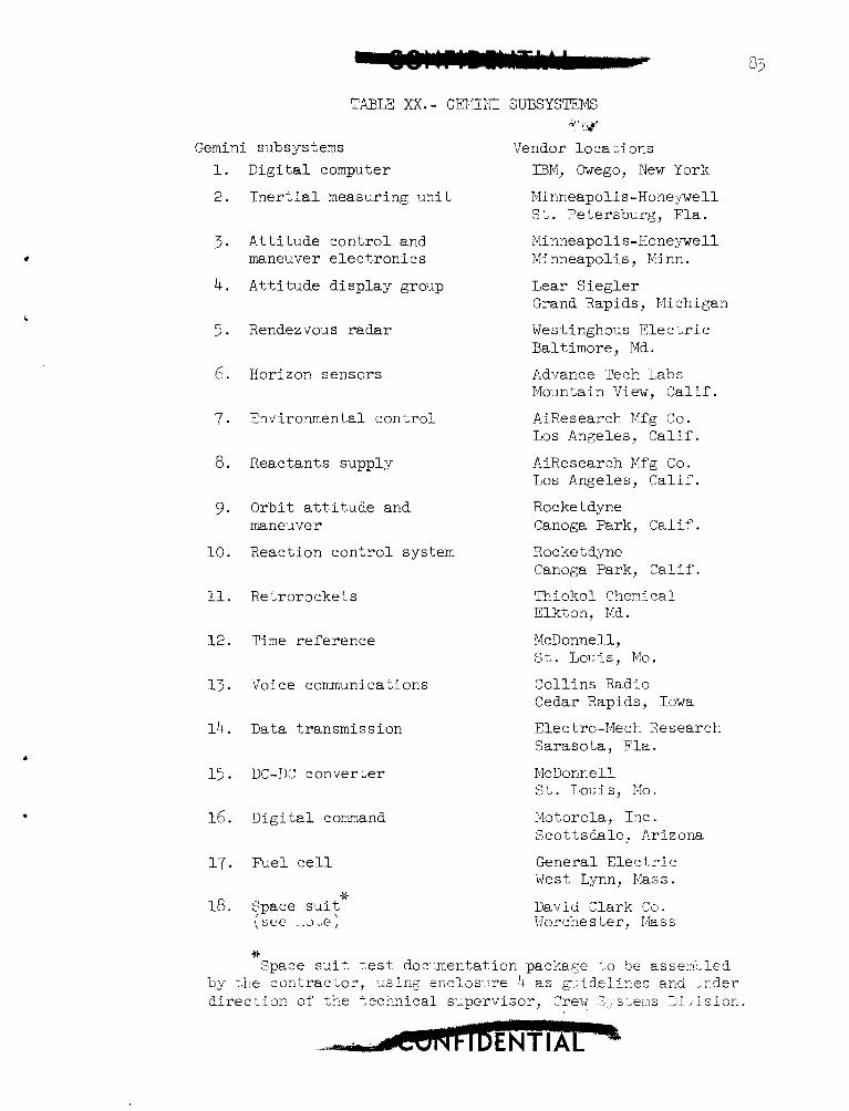
.
Gemini subsystems 1.
2.
3 .
4.
5 .
6.
7.
8 .
9.
10.
11.
12.
13.
14.
15 *
16.
17.
18.
Digital computer
Inertial measuring unit
Attitude control and maneuver electronics
Attitude display group
Rendezvous radar
Horizon sensors
Environmental control
Reactants supply
Orbit attitude and maneuver
Reaction control system
Retrorockets
Time reference
Voice communications
Data transmission
DC-DC converter
Digital command
PJel cell
36 $pace sui: ( s e e J " e )
'a' I ,,$
Vendor locations IBM, Owego, New York
Minneapolis-Honeywell St. Petersburg, Fla. Minneapolis-Honeywell Minneapolis , Minn. Lear Siegler Grand Rapids, Michigan
Westinghous Electric Baltimore, Md.
AdJance Tech Labs Mountain View, Calif.
AiResearch Mfg Co. Los Angeles, Calif.
AiResearch Mfg Co. Los Angeles, Calif.
Rocket dyne Canoga Park, Calif.
Rocket dyne Canoga Park, Calif. "hiokol Chemi ea1 Elkton, Md.
McDonnell, St. Louis, Mo.
Collins Radio Cedar Rapids, Iowa E l e c tro-Mech Research Sarasota, Fla.
McDonnell St. Louis, Mo.
Motorola, Inc. Scottsdale, Arizona
General Electric West Lynn, Nass.
DaviCi :lark 70. \lor che s t er I las s
+e Space s-it test doc.:mentation package i.0 S e asserrLled
by the contractor, -:.sing enclos-;.re 4 as g;ideli-r,es and ,rder direction of the tecknical s.J.pervisor, Crew ,3;,-sl;ems 5i /ision.
J
84
A comparison of spacecraft hardware configurations presently in production, with the configuration used in the Design Approval Tests is being made. from the design approval test configuration will require additional consideration to determine if the results of the tests can be csed to quzlify fully the hardware for manned flight. Future configurations yin@ into design approval tests will be synamomxs with prociuctim rirticlcs.
Those components whose production confiGration differs
A qualification status listing showing the planned and completed qualification status of each part, component, sub-assembly, and higher level assembly is being prepared.
An extensive effort to detect weaknesses in the failure reportin:: and failure analysis program is in process so that a timely and ef'fi- cient program can be realized prior to the first manned flight.
'l'wo reliability meetings were held at MSC to coordinate the reliability activities of 1,EC and the prime contractor.
PROGRAM ANALYSIS AND REVIEW
GEMINI SPACECRAFT
Continual efforts have been made to improve coordination and the flow of meaningful information between the Gemini Program Office, McDonnell Aircraft Corporation, and their subcontractors in the area of status control and cost/schedule correlation. these efforts is the establishment within McDonnell Aircraft CorporaLion of a Cost Evaluation Committee to assist in the timely evaluation of all phases of their Gemini effort. The committee consists of representatives from their engineering, manufacturing, procurement, budget, contracts, and program control organizations.
One of the results of
Evaluation by this committee is oriented primarily toward pre- diction of costs to completion of the various program elements dnder b'IcDonnell Aircraft Corporation * s responsibility, and is principally based upon correlation of accomplishments to date, work remaining, and costs incurred to date. Review and evaluation are Cerformec in cach 0' the approximately forty program control categories. Analysis is made of many factors, includirg engineering, development, test, and hard- ware production status; difficulties encountered or anticipated; effect, of changes and program reorientations; subcontractor performance; schedule maintenance; and manpower requirements history and projections
The r e s u l t s of t he c o r n i t t e e ' s analyses are documented i n b r i e f r e p o r t s s e t t i n g f o r t h pe r t inen t conclusions and recommendations. Upor! review of these conclusions and rscommendations and determinat ion of a c t i o n t o be taken, McDonnell A i r c r a f Y Corporation r e v i s e s t h e i r cos t p ro jec t ions . These r e v i s i o n s are r e f l e c t e d i n t h e N-4SA Form 533, Financ ia l S t a tus Report.
G E M I N I LAUNCH VEHICLE
A s one o f s i x subs id i a ry panels o f t he r e c e n t l y char te red G e a i n i Launch Vehicle Coordination Committee, a Cost, Contracts , and Schedules Panel has been e s t ab l i shed . This panel i s respons ib le f o r eva lua t ion of cos t , con t r ac t , and schedule information; program s t a t u s ; and advance determinat ion o f i tems adverse ly a f f e c t i n g maintenance o f program prog- ress milestones. Methods o f repor t ing c o s t s and c o r r e l a t i o n o f program pro,%ress and expendi ture of resources w i l l be a sub jec t o f primary c m - cern. T%e Cost, Contracts , and Schedule Panel w i l l bte compos?d of r ep res2n ta t ives o f t h e MSC Gemini Program Office, t h e MSC Program Analysis and Resoixces Management Off ice , t he MSC Gemini Procurement Off ice , the A i r Force Space System Divis ion, Martin Marietta Corporatior!/ Baltimore, Aerojet General Corporation, and Martin Mar ie t ta Corporation/ Cape Kenneciy.
REFE REY ZE
1. Evaluat ion o f a Ful l - sca le Gemini Abort System i n a n Al t i tude Tes t C e l l ( U ) , A E D . Z - T ~ R - ~ ~ - ~ ~ O , Confid?nt ia l Dozument, dated November 1963.
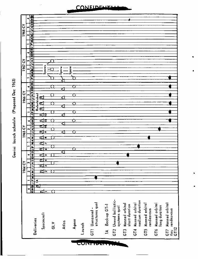
, 1-1
c Y
z V 0, U 0
v, n
0 C Q, cn U
-c U C
0 a -I