Embed Size (px)
Citation preview
1
SolarEdge Quick Installation Guide – North America
For full installation and safety details, you must refer to the SolarEdge Installation Guide. Make sure you read, fully understand and follow the detailed
instructions in the SolarEdge Installation Guide prior to each installation. Failure to do so could result in injury or loss of life and damage or destruction of the
equipment.
Connecting Power Optimizers to Modules
Mount the power optimizers in a shaded location near the PV modules, on the structure or racking to which the module is attached, using both mounting holes.
If possible, avoid mounting power optimizers in locations where they will be exposed to direct sunlight.
Make sure that each power optimizer is positioned within reach of each module’s cables.
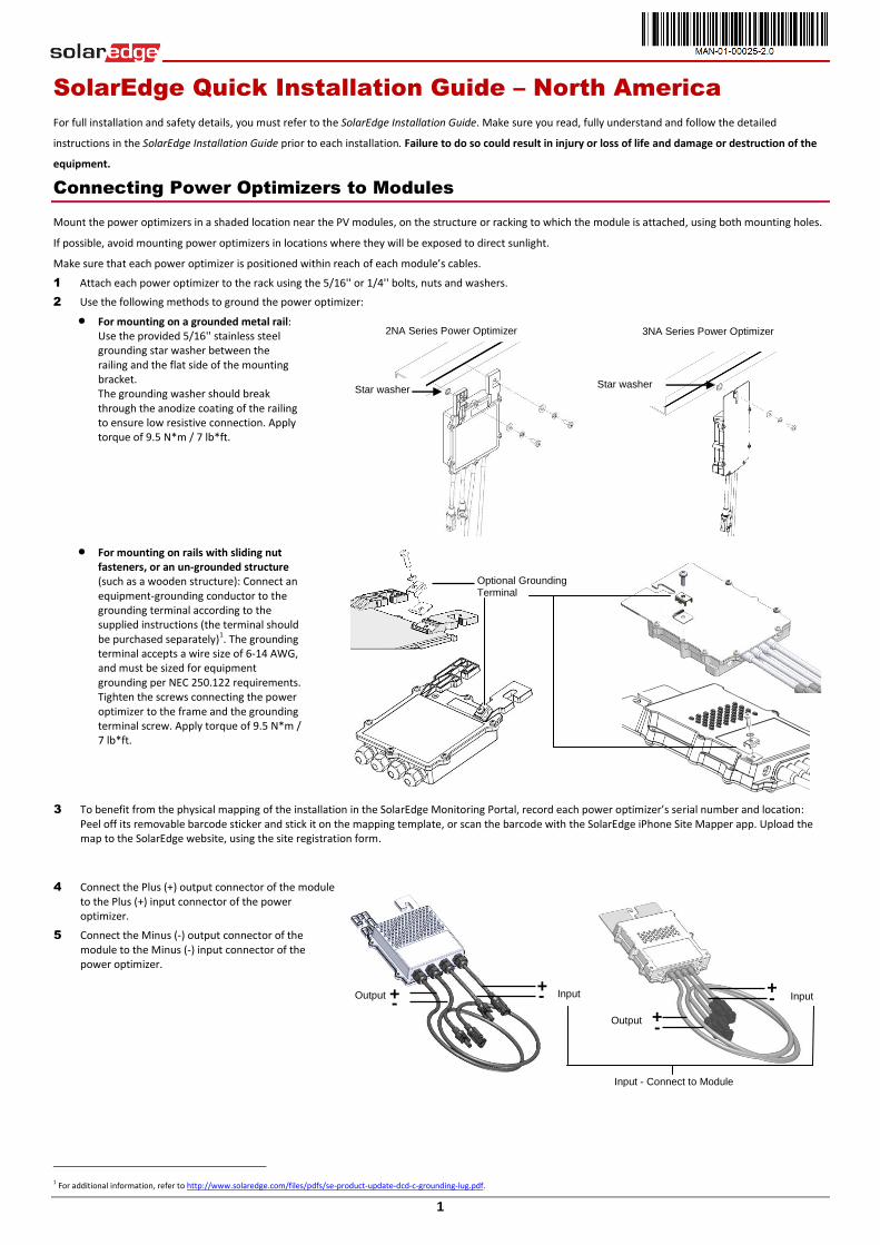
1 Attach each power optimizer to the rack using the 5/16'' or 1/4'' bolts, nuts and washers.
2 Use the following methods to ground the power optimizer:
For mounting on a grounded metal rail: Use the provided 5/16'' stainless steel grounding star washer between the railing and the flat side of the mounting bracket. The grounding washer should break through the anodize coating of the railing to ensure low resistive connection. Apply torque of 9.5 N*m / 7 lb*ft.
For mounting on rails with sliding nut fasteners, or an un-grounded structure (such as a wooden structure): Connect an equipment-grounding conductor to the grounding terminal according to the supplied instructions (the terminal should be purchased separately)1. The grounding terminal accepts a wire size of 6-14 AWG, and must be sized for equipment grounding per NEC 250.122 requirements. Tighten the screws connecting the power optimizer to the frame and the grounding terminal screw. Apply torque of 9.5 N*m / 7 lb*ft.
3 To benefit from the physical mapping of the installation in the SolarEdge Monitoring Portal, record each power optimizer’s serial number and location: Peel off its removable barcode sticker and stick it on the mapping template, or scan the barcode with the SolarEdge iPhone Site Mapper app. Upload the map to the SolarEdge website, using the site registration form.
4 Connect the Plus (+) output connector of the module to the Plus (+) input connector of the power optimizer.
5 Connect the Minus (-) output connector of the module to the Minus (-) input connector of the power optimizer.
1 For additional information, refer to http://www.solaredge.com/files/pdfs/se-product-update-dcd-c-grounding-lug.pdf.
+ -
Input - + Output -
+
Output
Input
-
+
Input - Connect to Module
Optional Grounding Terminal
3NA Series Power Optimizer
Star washer
2NA Series Power Optimizer
Star washer
MAN-01-00025-2.0
2
Mounting Bracket Orientation
Bracket Screw
Loosen these screws
Connecting Power Optimizers to a String
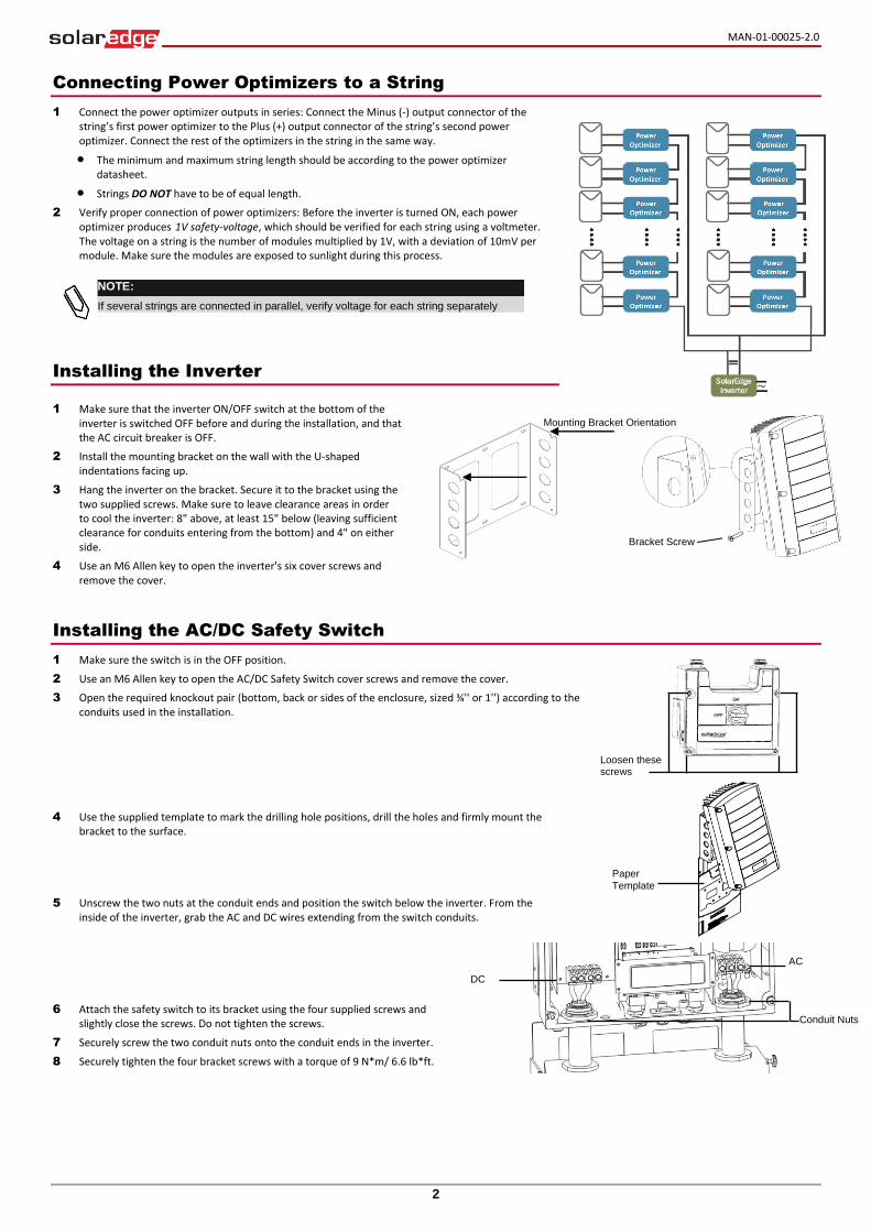
1 Connect the power optimizer outputs in series: Connect the Minus (-) output connector of the string’s first power optimizer to the Plus (+) output connector of the string’s second power optimizer. Connect the rest of the optimizers in the string in the same way.
The minimum and maximum string length should be according to the power optimizer datasheet.
Strings DO NOT have to be of equal length.
2 Verify proper connection of power optimizers: Before the inverter is turned ON, each power optimizer produces 1V safety-voltage, which should be verified for each string using a voltmeter. The voltage on a string is the number of modules multiplied by 1V, with a deviation of 10mV per module. Make sure the modules are exposed to sunlight during this process.
Installing the Inverter
1 Make sure that the inverter ON/OFF switch at the bottom of the inverter is switched OFF before and during the installation, and that the AC circuit breaker is OFF.
2 Install the mounting bracket on the wall with the U-shaped indentations facing up.
3 Hang the inverter on the bracket. Secure it to the bracket using the two supplied screws. Make sure to leave clearance areas in order to cool the inverter: 8" above, at least 15" below (leaving sufficient clearance for conduits entering from the bottom) and 4" on either side.
4 Use an M6 Allen key to open the inverter's six cover screws and remove the cover.
Installing the AC/DC Safety Switch
1 Make sure the switch is in the OFF position.
2 Use an M6 Allen key to open the AC/DC Safety Switch cover screws and remove the cover.
3 Open the required knockout pair (bottom, back or sides of the enclosure, sized ¾'' or 1'') according to the conduits used in the installation.
4 Use the supplied template to mark the drilling hole positions, drill the holes and firmly mount the bracket to the surface.
5 Unscrew the two nuts at the conduit ends and position the switch below the inverter. From the inside of the inverter, grab the AC and DC wires extending from the switch conduits.
6 Attach the safety switch to its bracket using the four supplied screws and slightly close the screws. Do not tighten the screws.
7 Securely screw the two conduit nuts onto the conduit ends in the inverter.
8 Securely tighten the four bracket screws with a torque of 9 N*m/ 6.6 lb*ft.
NOTE:
If several strings are connected in parallel, verify voltage for each string separately
Paper
Template
DC
AC
Conduit Nuts
MAN-01-00025-2.0
3
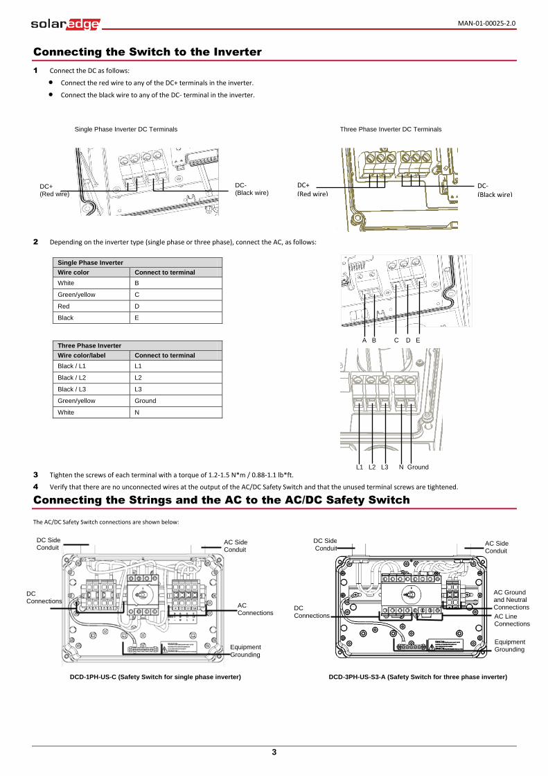
Connecting the Switch to the Inverter
1 Connect the DC as follows:
Connect the red wire to any of the DC+ terminals in the inverter.
Connect the black wire to any of the DC- terminal in the inverter.
2 Depending on the inverter type (single phase or three phase), connect the AC, as follows:
Single Phase Inverter
Wire color Connect to terminal
White B
Green/yellow C
Red D
Black E
Three Phase Inverter
Wire color/label Connect to terminal
Black / L1 L1
Black / L2 L2
Black / L3 L3
Green/yellow Ground
White N
3 Tighten the screws of each terminal with a torque of 1.2-1.5 N*m / 0.88-1.1 lb*ft.
4 Verify that there are no unconnected wires at the output of the AC/DC Safety Switch and that the unused terminal screws are tightened.
Connecting the Strings and the AC to the AC/DC Safety Switch
The AC/DC Safety Switch connections are shown below:
DC+ (Red wire)
DC- (Black wire)
DC+ (Red wire)
Single Phase Inverter DC Terminals Three Phase Inverter DC Terminals
DCD-1PH-US-C (Safety Switch for single phase inverter) DCD-3PH-US-S3-A (Safety Switch for three phase inverter)
AC Side Conduit
DC Side Conduit
Equipment
Grounding
AC Connections
AC Side Conduit
DC Side Conduit
Equipment Grounding
DC Connections AC Line
Connections
AC Ground and Neutral Connections
DC Connections
A B C D E
DC- (Black wire)
L1 L2 L3 N Ground
MAN-01-00025-2.0
4
Mini USB
Ethernet
RS232/RS485
Mini USB
Ethernet (RJ45)
RS232/RS485
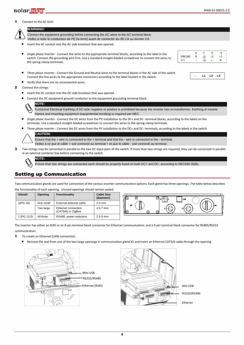
1 Connect to the AC Grid:
Insert the AC conduit into the AC-side knockout that was opened.
Single phase inverter - Connect the wires to the appropriate terminal blocks, according to the label in the switch. Connect the grounding wire first. Use a standard straight-bladed screwdriver to connect the wires to the spring-clamp terminals.
Three phase inverter - Connect the Ground and Neutral wires to the terminal blocks in the AC side of the switch. Connect the line wires to the appropriate connectors according to the label located in the switch.
Verify that there are no unconnected wires.
2 Connect the strings:
Insert the DC conduit into the DC-side knockout that was opened.
Connect the DC equipment ground conductor to the equipment grounding terminal block.
NOTE:
Functional Electrical Earthing of DC-side negative or positive is prohibited because the inverter has no transformer. Earthing of module
frames and mounting equipment (equipotential bonding) is required per NEC.
Single phase inverter - Connect the DC wires from the PV installation to the DC+ and DC- terminal blocks, according to the labels on the terminals. Use a standard straight-bladed screwdriver to connect the wires to the spring-clamp terminals.
Three phase inverter - Connect the DC wires from the PV installation to the DC+ and DC- terminals, according to the labels in the switch
CAUTION:
Ensure that the + wire is connected to the + terminal and that the - wire is connected to the - terminal.
Veillez à ce que le câble + soit connecté au terminal + et que le câble - soit connecté au terminal.
3 Two strings may be connected in parallel to the two DC input pairs of the switch. If more than two strings are required, they can be connected in parallel in an external combiner box before connecting to the switch.
NOTE:
If more than two strings are connected each should be properly fused on both DC+ and DC- according to NEC690.35(B).
Setting up Communication
Two communication glands are used for connection of the various inverter communication options. Each gland has three openings. The table below describes
the functionality of each opening. Unused openings should remain sealed.
Gland# Opening Functionality Cable Size (diameter)
1(PG 16) One small External antenna cable 2-4 mm
Two large Ethernet connection (CAT5/6) or ZigBee
4.5-7 mm
2 (PG 13.5) All three RS485, power reduction 2.5-5 mm
The inverter has either an RJ45 or an 8-pin terminal block connector for Ethernet communication, and a 9-pin terminal block connector for RS485/RS232
communication. 1 To create an Ethernet (LAN) connection:
Remove the seal from one of the two large openings in communication gland #1 and insert an Ethernet CAT5/6 cable through the opening.
WARNING!
Connect the equipment grounding before connecting the AC wires to the AC terminal block.
Veillez à relier le conducteur de PE (la terre) avant de connecter les fils CA au bornier CA.
- L1 L2 L3
MAN-01-00025-2.0
5
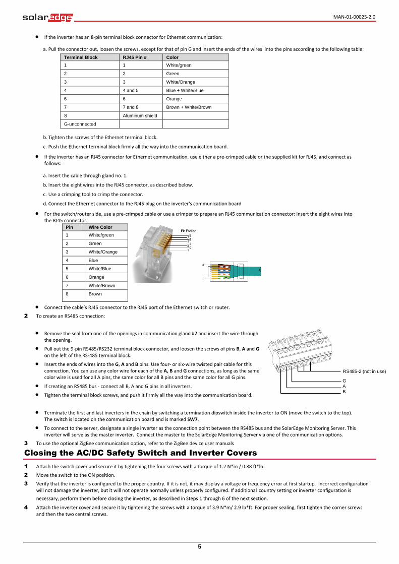
G A B
RS485-2 (not in use)
If the inverter has an 8-pin terminal block connector for Ethernet communication:
a. Pull the connector out, loosen the screws, except for that of pin G and insert the ends of the wires into the pins according to the following table:
Terminal Block RJ45 Pin # Color
1 1 White/green
2 2 Green
3 3 White/Orange
4 4 and 5 Blue + White/Blue
6 6 Orange
7 7 and 8 Brown + White/Brown
S Aluminum shield
G-unconnected
b. Tighten the screws of the Ethernet terminal block.
c. Push the Ethernet terminal block firmly all the way into the communication board.
If the inverter has an RJ45 connector for Ethernet communication, use either a pre-crimped cable or the supplied kit for RJ45, and connect as follows:
a. Insert the cable through gland no. 1.
b. Insert the eight wires into the RJ45 connector, as described below.
c. Use a crimping tool to crimp the connector.
d. Connect the Ethernet connector to the RJ45 plug on the inverter's communication board
For the switch/router side, use a pre-crimped cable or use a crimper to prepare an RJ45 communication connector: Insert the eight wires into the RJ45 connector.
Pin Wire Color
1 White/green
2 Green
3 White/Orange
4 Blue
5 White/Blue
6 Orange
7 White/Brown
8 Brown
Connect the cable’s RJ45 connector to the RJ45 port of the Ethernet switch or router.
2 To create an RS485 connection:
Remove the seal from one of the openings in communication gland #2 and insert the wire through the opening.
Pull out the 9-pin RS485/RS232 terminal block connector, and loosen the screws of pins B, A and G on the left of the RS-485 terminal block.
Insert the ends of wires into the G, A and B pins. Use four- or six-wire twisted pair cable for this connection. You can use any color wire for each of the A, B and G connections, as long as the same color wire is used for all A pins, the same color for all B pins and the same color for all G pins.
If creating an RS485 bus - connect all B, A and G pins in all inverters.
Tighten the terminal block screws, and push it firmly all the way into the communication board.
Terminate the first and last inverters in the chain by switching a termination dipswitch inside the inverter to ON (move the switch to the top). The switch is located on the communication board and is marked SW7.
To connect to the server, designate a single inverter as the connection point between the RS485 bus and the SolarEdge Monitoring Server. This inverter will serve as the master inverter. Connect the master to the SolarEdge Monitoring Server via one of the communication options.
3 To use the optional ZigBee communication option, refer to the ZigBee device user manuals
Closing the AC/DC Safety Switch and Inverter Covers
1 Attach the switch cover and secure it by tightening the four screws with a torque of 1.2 N*m / 0.88 ft*lb:
2 Move the switch to the ON position.
3 Verify that the inverter is configured to the proper country. If it is not, it may display a voltage or frequency error at first startup. Incorrect configuration will not damage the inverter, but it will not operate normally unless properly configured. If additional country setting or inverter configuration is
necessary, perform them before closing the inverter, as described in Steps 1 through 6 of the next section.
4 Attach the inverter cover and secure it by tightening the screws with a torque of 3.9 N*m/ 2.9 lb*ft. For proper sealing, first tighten the corner screws and then the two central screws.
MAN-01-00025-2.0
6
Support and Contact Information
If you have technical problems concerning our products, please contact us:
USA and Canada: +1 (0) 877 360 5292
Worldwide: +972 (0) 73 240-3118
Fax: +1 (0) 530 273-2769
Email to [email protected]
Commissioning and Activating the Installation
1 Verify that the inverter ON/OFF switch is OFF.
2 Activate the inverter according to the activation instructions supplied with the inverter.
3 Turn ON the AC breaker.
WARNING!
High AC voltage is present in the inverter – HANDLE WITH CARE!.
Une haute tension CA est présente dans l’onduleur – MANIPULEZ AVEC PRECAUTIONS !
4 Turn ON the AC/DC Safety Switch. If an additional external DC switch is installed between the power optimizers and the inverter(s) then turn it ON. A message similar to the following appears on the inverter LCD panel:
V a c [ v ] V d c [ v ] P a c [ w ]
2 4 0 . 7 1 4 . 1 0 . 0
P _ O K : 0 0 0 / 0 0 0 < S _ O K >
O F F
5 Verify the following in the LCD display:
Vac: Specifies the grid voltage.
Vdc[V]: The DC input voltage of the longest string connected to the inverter. There should be a safety voltage of 1V for each power optimizer in the string
Pac[W]: AC power production. At this stage, it should be 0w.
P-OK: Specifies the number of properly connected power optimizers.
S-OK: Indicates the status of the connection to the SolarEdge monitoring portal (if connected).
6 Configure the country code, display language and communication configuration using the inverter user buttons and LCD. The buttons are located just above the LCD and are numbered esc, 1, 2, 3/Enter from left to right. Enter the menus by pressing ENTER for five seconds and then inputting the password 12312312. To verify that the country code is set to USA, select Country from the main menu, press Enter and select USA+. In the next menu that appears, select the desired AC grid configuration.
7 Close the inverter cover.
WARNING!
Before proceeding to the next step, make sure that the cover is closed! High DC Voltage will be present in the inverter following the next step!
Avant d’entamer la prochaine étape, assurez vous que le couvercle est fermé ! Une tension DC très haute sera présente durant l’étape suivante !
8 Make sure that the ON/OFF switch at the bottom of the inverter is OFF.
9 To pair the power optimizers to the inverter, press and hold down the inverter LCD button for about 10 seconds. The following message is displayed:
K e e p h o l d i n g b u t t o n
f o r p a i r i n g , r e l e a s e
t o e n t e r m e n u . . .
R e m a i n i n g : 3 s e c
Keep holding for 5 seconds until the following is displayed:
P a i r i n g
T u r n S w i t c h T o O n
10 Turn the inverter ON within 5 seconds. If you wait longer than 5 seconds, the inverter exits the pairing mode. The following message is displayed indicating that the inverter is performing the pairing.
P a i r i n g
R e m a i n i n g [ s e c ] : 1 8 0
11 Wait for the completion of the pairing (remaining seconds is 0). If pairing fails, an error is displayed. In this case, repeat the pairing steps. When pairing succeeds, the following message is displayed:
P a i r i n g
P a i r i n g C o m p l e t e d
12 At the end of the pairing process, the system will start producing power. Verify on the LCD screen that the number next to P_OK equals the number of installed power optimizers. It may take up to 20 minutes until all the power optimizers are indicated.
WARNING!
After you turn ON the inverter ON/OFF switch, the DC cables carry a high voltage and the power optimizers no longer output a safe 1V output.
Après avoir mis l'interrupteur ON/OFF de l'onduleur monophasé sur ON, les câbles DC portent une haute tension et les optimiseurs de puissance ne génèrent plus la tension de sécurité de 1V.
WARNING!
After you turn OFF the inverter ON/OFF switch, wait until the LCD indicates that the DC voltage is safe (<50V), or wait five minutes before
opening the cover or disconnecting the strings.
Apres avoir tourné l’interrupteur ON/OFF sur OFF, attendre jusqu'à ce que l’écran LCD indique que la tension DC est sécurisée (<50V) ou attendre cinq minutes avant d’ouvrir le couvercle ou de déconnecter les strings.
Refer to the SolarEdge Installation Guide for detailed installation
and safety instructions.

![Quick Installation Guide – PS107 - SEH Technology · @ support@seh.de Print Server PS107 Quick Installation Guide Overview [en] This Quick Installation Guide provides a description](https://img.pdfslide.net/doc/110x75/60636d0038f9905e874fdfb6/quick-installation-guide-a-ps107-seh-technology-supportsehde-print-server.jpg)