Embed Size (px)
Citation preview
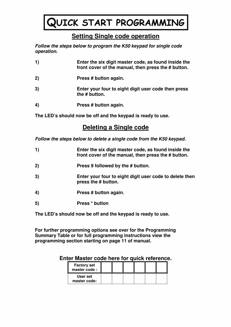
QUICK START PROGRAMMING
Setting Single code operation
Follow the steps below to program the K50 keypad for single code operation. 1) Enter the six digit master code, as found inside the
front cover of the manual, then press the # button. 2) Press # button again. 3) Enter your four to eight digit user code then press
the # button. 4) Press # button again. The LED’s should now be off and the keypad is ready to use.
Deleting a Single code Follow the steps below to delete a single code from the K50 keypad. 1) Enter the six digit master code, as found inside the
front cover of the manual, then press the # button. 2) Press 9 followed by the # button. 3) Enter your four to eight digit user code to delete then
press the # button. 4) Press # button again. 5) Press * button The LED’s should now be off and the keypad is ready to use. For further programming options see over for the Programming Summary Table or for full programming instructions view the programming section starting on page 11 of manual.
Enter Master code here for quick reference.
Factory set master code :
User set master code:

RAYTEL SECURITY SYSTEMS LIMITED
Access Control Keypad
Table of Users and Keypad Parameters
Installation Company: ………………………..………………. Tel: ……………………….…………… Date: ….………….…...…
Name of On-Site Programmer(s): …………………………………………..………………………………………………….…………………….....
Master Code FMC: …………………….………..…….……………...….…..…. UMC (If Set): …………..…..……..….…….……..…..…….…….
Unit Type: ……….…..………..………………….….. Lock Time: .……..……..…Seconds Serial Number: .……………………....….……
Time Zone Periods: TZ1 from to
(If Set) TZ2 from to TZ3 from to
TZ4 from to TZ5 from to
Latch Mode Time: from to Service Mode Time: from to
No. NAME CODE TIME ZONE LATCH CODE SERVICE CODE DATE
1
2
3
4
5
6
7
8
9
10
11
12
13
14
15
16
17
18
19
20
21
22
23
24
25
26
27
28
29
30
31
32
33
34
35
36
37
38
39
40
41
42
43
44
45
46
47
48
49
50
We recommend this page should be filled in and regularly updated and kept in a safe and secure location by the person responsible for the upkeep of the system.

Southern Office Raytel Security Systems Ltd. Northern Office
Tel. 01268 775656 Fax. 01268 745001 Tel. 0141 3324232 Fax. 0141 3326952
The Digitac K50
Access Control System
Installation and User Manual Issue 2 – May 2001
IMPORTANT NOTE
Please keep this manual in a safe
place with the premises Key holder.
The Factory Master Code is inside.

Southern Office Raytel Security Systems Ltd. Northern Office
Tel. 01268 775656 Fax. 01268 745001 Tel. 0141 3324232 Fax. 0141 3326952
1
Factory Master Code
The Factory Master Code allows access to the programming modes of the K50. It is
recommended that this manual be kept in a safe place for future reference.
Factory Master Code
Unit Serial Number
If the Factory Master Code is reprogrammed the new User Master Code should be
noted below.
User Master Code
Declaration of Conformity
We, Raytel Security Systems Ltd, declare that the equipment
referred to within this document, conforms to the European
Commission Electromagnetic Compatibility (EMC) Directive
(Directive 89/336/EEC) when installed in strict accordance with
the guidelines contained within this document.
Technical Support
For all technical enquiries relating to this equipment, engineers are available at the following addresses:
Rayleigh Office Glasgow Office
Raytel House Unit 3, Block 5
Brook Road Oakbank Industrial Estate
Rayleigh Garscube Road
Essex Glasgow
SS6 7XH G20 7LU
Tel: (01268) 749310 Tel (0141) 3324232
Fax: (01268) 745001 Fax (0141) 3326952
Raytel Security reserves the right to change the content of this manual and product
design without prior notice.
VERY IMPORTANT PLEASE KEEP SAFE

Southern Office Raytel Security Systems Ltd. Northern Office
Tel. 01268 775656 Fax. 01268 745001 Tel. 0141 3324232 Fax. 0141 3326952
2
Index
GENERAL DESCRIPTION..................................................................................................................4
OPERATION ..........................................................................................................................................4
AUDIBLE AND VISUAL INDICATIONS ....................................................................................................4
• Key press Confirmation. ...........................................................................................................4
• Valid Code. ...............................................................................................................................4
• Invalid Code .............................................................................................................................4
• Invalid Data..............................................................................................................................4
ADDITIONAL FEATURES ......................................................................................................................5
Code Entry Timer ............................................................................................................................5
Code Capacity ..................................................................................................................................5
Master Code .....................................................................................................................................5
Timed Code Operation.....................................................................................................................5
Tamper Switch .................................................................................................................................5
Timed Lock Operation .....................................................................................................................5
Exit Button .......................................................................................................................................5
Service Mode....................................................................................................................................5
Latch Mode ......................................................................................................................................6
Self Test............................................................................................................................................6
Master Reset.....................................................................................................................................6
INSTALLATION ...................................................................................................................................7
CONTROL UNIT ....................................................................................................................................7
SEALING ...............................................................................................................................................7
POWER SUPPLY....................................................................................................................................7
ELECTRIC RELEASE.............................................................................................................................7
EXIT BUTTON .......................................................................................................................................7
CABLE COLOUR CODE.........................................................................................................................8
WIRING SCHEMATICS ......................................................................................................................9
WIRING FOR K50 USING AN AC SUPPLY WITH AN AC FAIL SECURE RELEASE .............................9
WIRING FOR K50 USING A DC SUPPLY AND DC FAIL SECURE RELEASE.........................................10
WIRING FOR K50 USING A DC SUPPLY AND DC FAIL SAFE RELEASE .............................................11
WIRING FOR K50 TAMPER RELAY AND DC FAIL SAFE RELEASE ...................................................12
WIRING FOR K50 TAMPER RELAY AND DC FAIL SECURE RELEASE...............................................13
WIRING FOR KA1-KA3 AND AC FAIL SECURE RELEASE ................................................................14
WIRING FOR KA1-KA3 AND ELVOX GATE SYSTEM ........................................................................15
WIRING FOR KA1 – KA3 WITH DC FAIL SAFE RELEASE.................................................................16
WIRING FOR KV1 SYSTEM AND AC FAIL SECURE RELEASE ...........................................................17
WIRING FOR KV1 – KV3 AND AC FAIL SECURE RELEASE ..............................................................18
QUICK PROGRAMMING GUIDE. ..................................................................................................19
PROGRAMMING A CODE.....................................................................................................................19
DELETING A CODE..............................................................................................................................19
SETTING THE LOCK RELAY TIME .....................................................................................................20
ACTIVATING THE K50 SELF TEST MODE ...........................................................................................20
K50 Test sequence .........................................................................................................................21
ADVANCED PROGRAMMING GUIDE. .........................................................................................22
PERFORMING A MASTER RESET .......................................................................................................22
SETTING THE LOCK RELAY TIME .....................................................................................................23
INSTALLING USER CODES..................................................................................................................24
SETTING THE CLOCK.........................................................................................................................25
SETTING SERVICE MODE...................................................................................................................26
To Enter Service Mode Manually .................................................................................................26
To exit Service mode......................................................................................................................26
To Set Service Mode for timed operation......................................................................................26

Southern Office Raytel Security Systems Ltd. Northern Office
Tel. 01268 775656 Fax. 01268 745001 Tel. 0141 3324232 Fax. 0141 3326952
3
Index
SETTING LATCH MODE .....................................................................................................................27
To Enter Latch Mode Manually....................................................................................................27
To exit Latch mode ........................................................................................................................27
To Set Latch Mode for timed operation ........................................................................................27
SETTING SOUNDER OPERATION.........................................................................................................28
CODE CAPACITY CHECK ...................................................................................................................29
ACCESS LEVELS AND TIME ZONES ...................................................................................................30
Programming Time Zone settings .................................................................................................31
DELETING A SINGLE USER CODE .......................................................................................................32
DELETING ALL USER CODES.............................................................................................................33
CHANGING THE MASTER CODE ........................................................................................................34
TECHNICAL INFORMATION .........................................................................................................35
PROGRAMMING SUMMARY TABLE ...........................................................................................36

Southern Office Raytel Security Systems Ltd. Northern Office
Tel. 01268 775656 Fax. 01268 745001 Tel. 0141 3324232 Fax. 0141 3326952
4
General Description
Typical K50
Installation
Open
Area
Secure
Area
Power
Supply
Mains
Exit
Push
K50
Electric
Release
General Description
The K50 is a compact self-contained
access control unit, (which may also be
incorporated into audio and video
entrance panels), designed for single
door operation. Installation is quick and
simple, with all programming done via
the keypad.
Operation
A person wishing to gain access to the
secure area will enter their user code via
the keypad. If the correct code has been
entered the lock output relay will operate
for the pre-set time. If the code entered is
incorrect, subsequent key presses will be ignored for six
seconds, the last two seconds of which will be accompanied by a continuous
error tone. This makes code breaking by trial and error more difficult.
Audible and visual indications
During normal operation of the K50 the following audible / visual responses
will be encountered.
• Key press Confirmation.
When a button is pressed, except the *, the K50 will respond with a
short tone accompanied by the RED LED flashing on / off.
• Valid Code.
When a valid user code is entered or the exit button is operated the
output relay will operate for a pre-set time. A tone and illumination of
the GREEN LED accompany this. This will continue while the output
relay is in operation.
• Invalid Code
If an invalid code is entered the K50 waits four seconds before
sounding a low frequency tone; this is accompanied by the illumination
of the RED LED. This error tone lasts for two seconds.
During program mode in addition to the Key press Confirmation and the
indications as detailed in the individual programming tables the following
audible / visual response may be encountered.
• Invalid Data.
If invalid data is entered e.g. trying to add a user code that already
exists the K50 will emit a low frequency tone; this is accompanied by
the illumination of the RED LED. This error tone lasts for two
seconds.

Southern Office Raytel Security Systems Ltd. Northern Office
Tel. 01268 775656 Fax. 01268 745001 Tel. 0141 3324232 Fax. 0141 3326952
5
General Description
Additional Features
Code Entry Timer
A delay of more than four seconds between successive key presses will
register as an incorrect code, subsequent key presses will be ignored for six
seconds, the last two seconds of which will be accompanied by a continuous
error tone.
Code Capacity
The K50 has the capacity to store up to fifty access codes of four to eight
digits. The codes are stored in EPROM and therefore will be retained even if
the power is removed.
Master Code
The Master code is used to access all the programming features. Each unit is
factory programmed with its own unique master code. This code can be found
on the inside cover of this manual. For additional security it is possible to
reprogram the master code. The new code should be noted in the space
provided inside the front cover of this manual, which should then be kept in a
restricted, secure location.
Timed Code Operation
During normal operation, entering a valid code at any time will activate the
door release. Optionally up to two sets of time zone markers may be
programmed into the controller giving six access periods. This allows
different codes to be assigned to different security levels. Please refer to the
section on Access Levels and Time Zones starting on page 30 of this manual.
Tamper Switch
When the unit is installed the tamper switch lever is depressed by contact
against the mounting surface. This makes a short circuit between the two
tamper alarm cables (yellow and white cables in multicore). If the unit is
removed, the tamper switch opens breaking the circuit between the two tamper
alarm cables. This change in state may be used to operate a remote alarm if
required.
Timed Lock Operation
The lock output relay operation time is adjustable between one and ninety nine
seconds in one-second increments.
Exit Button
A normally open push button may be fitted to give lock operation from within
the secure area.
Service Mode
During service mode operation, pressing any button on the keypad will operate
the lock output relay for the pre-set lock time. This option is designed for use
with fail secure releases.

Southern Office Raytel Security Systems Ltd. Northern Office
Tel. 01268 775656 Fax. 01268 745001 Tel. 0141 3324232 Fax. 0141 3326952
6
General Description
Latch Mode
Latch mode is used to latch the lock output relay on. This can be done
manually, using the master code to turn latch mode on or off or, programmed
to automatically operate during certain access periods. This option is only
recommended for use with fail safe door releases.
Self Test
The unit has a self-diagnostic mode. When entered it allows the controller and
keypad functions to be tested with audible and visual confirmation of the
results.
Master Reset
The master reset will clear all user codes and reset all functions to their factory
defaults, including the factory user code.

Southern Office Raytel Security Systems Ltd. Northern Office
Tel. 01268 775656 Fax. 01268 745001 Tel. 0141 3324232 Fax. 0141 3326952
7
Installation
Installation
Control Unit The control unit should be securely attached to a wall adjacent to the entrance
that it controls. Care should be taken to establish that the wall upon which the
unit is to be mounted is of sufficient size and construction to meet the
dimensions and weight of the control unit.
If any risk of flooding or free flowing water is apparent, the control unit
should be fitted in a position that will provide adequate protection from the
ingress of moisture.
The control unit should be mounted at such a height, approximately 1.3
meters, 1.5 meters for integrated audio / video panels, that it can be used
without undue difficulty.
Sealing
Ensure the unit is adequately sealed, using a flexible sealing compound, to
prevent moisture ingress. The unit should be sealed on the top, left and right
edges, the bottom edge should be left unsealed to allow for drainage and
ventilation. For flush installations, ensure that the front edge of the flush box
is installed level with the mounting surface such that when the front panel is
fitted, it rests against this edge without gaps.
Power Supply
The K50 requires a supply of 10 – 16V AC or 10 – 28V DC at 100mA. This
should be located on an inside wall within the secure area and supplied with
240V 50Hz AC mains. If the K50 is to function during mains failure a 12V
DC supply with a battery standby facility should be used.
Electric Release
This should be fitted according to the manufacturer’s instructions and comply
with the relevant statutory regulations. Note that only 12V DC releases can be
used if the unit is to operate during main failure. It is strongly recommended
that a break glass unit be fitted on installations using fail safe releases. For
installations using fail secure releases a mechanical override e.g. internal
handle should be fitted.
Exit Button
This should have normally open contacts and be located within the secure
area.

Southern Office Raytel Security Systems Ltd. Northern Office
Tel. 01268 775656 Fax. 01268 745001 Tel. 0141 3324232 Fax. 0141 3326952
8
Installation
Cable Colour Code
The K50 comes supplied with two meters of twelve-core cable. The following
chart gives details of core usage.
Cable Colour Usage
Red Power input + ve
Black Power Input - ve
Yellow & White Tamper Switch Output
Green & Blue Exit Button Input
Violet & Brown Clean Contact Output (Common)
Grey & Turquoise Clean Contact Output (Normally Closed)
Orange & Pink Clean Contact Output (Normally Open)

Southern Office Raytel Security Systems Ltd. Northern Office
Tel. 01268 775656 Fax. 01268 745001 Tel. 0141 3324232 Fax. 0141 3326952
9
Wiring Schematics
Wiring Schematics
Wiring for K50 using an AC supply with an AC Fail Secure release
DE
SC
RIP
TIO
ND
AT
ET
ITL
ED
RA
WN
CH
EC
KE
DA
PP
RO
VE
DD
AT
E
INIT
IAL
TH
E R
AY
TE
L G
RO
UP
LT
D.
DR
AW
ING
No.
BP
M
ISS
ISS
1
RG
D 5
006
/ 15
INS
TA
LL
AT
ION
WIR
ING
SC
HE
MA
TIC
FO
R A
CC
ES
S C
ON
TR
OL
LE
R K
50
OP
ER
AT
ING
FR
OM
AN
AC
SU
PP
LY
.
25 -
4 -
95
25 -
4 -
95
FU
NC
TIO
NA
CC
ES
S
K5
0
DIG
ITA
C
12
3
45
6
78
9
0
ELV
OX
Art.
08
32
/00
0
Pri
ma
ry2
40
V a
c
50
/60
Hz.
Se
co
nd
ary
12
V a
c 2
0 V
A.
12V
EX
IT
CO
M
NO
NC
RE
D
BL
AC
K
WH
ITE
YE
LL
OW
GR
EE
NB
LU
E
NO
RM
ALL
Y C
LOS
ED
LO
OP
EX
IT B
UT
TO
N
TA
MP
ER
TA
MP
ERT
AM
PE
R
EX
IT
12
Va
c
DO
OR
RE
LE
AS
E
MA
INS
VO
LT
AG
E2
30
Va
c
50
Hz
12
Va
c P
OW
ER
SU
PP
LY
SE
CU
RE
A
RE
A
AC
CE
SS
CO
NT
RO
LL
ER
( V
AR
IAN
TS
K
50
S &
K5
0B
)
JUN
CT
ION
BO
X
MO
DE
L -
K5
0
MO
DE
L -
83
2/0
00
FA
IL S
EC
UR
E (
LO
CK
ED
)
MO
DE
L -
JB
72
0
( VA
RIA
NT
S V
SE
1 &
VFE
1 )
CA
BL
E2
me
tre
s.
MU
LT
ICO
RE
OR
AN
GE
& P
INK
GR
EY
& T
UR
QU
OIS
E
VIO
LE
T &
BR
OW
N
IND
ICA
TE
S O
PT
ION
AL
W
IRIN
G A
ND
EQ
UIP
ME
NT
.
TA
MP
ER
ALA
RM
OU
TP
UT
MO
DE
L - S
E1

Southern Office Raytel Security Systems Ltd. Northern Office
Tel. 01268 775656 Fax. 01268 745001 Tel. 0141 3324232 Fax. 0141 3326952
10
Wiring Schematics
Wiring for K50 using a DC supply and DC Fail Secure release
DE
SC
RIP
TIO
ND
AT
ET
ITL
ED
RA
WN
CH
EC
KE
DA
PP
RO
VE
DD
AT
E
INIT
IAL
TH
E R
AY
TE
L G
RO
UP
LT
D.
DR
AW
ING
No.
BP
M
ISS
ISS
1
RG
D 5
006 /
21
INS
TA
LL
AT
ION
WIR
ING
SC
HE
MA
TIC
FO
R A
CC
ES
S C
ON
TR
OL
LE
R K
50
OP
ER
AT
ING
FR
OM
A D
C S
UP
PL
Y.
2 -
5 -
952
- 5
- 95
FU
NC
TIO
NA
CC
ES
S
K5
0
DIG
ITA
C
12
3
45
6
78
9
0
EX
IT
CO
M
NO
NC
RE
D
BL
AC
K
WH
ITE
YE
LL
OW
GR
EE
NB
LU
E
EX
IT B
UT
TO
N
TA
MP
ER
TA
MP
ER
TA
MP
ER
EX
IT
DO
OR
RE
LE
AS
E
AC
CE
SS
CO
NT
RO
LL
ER
( V
AR
IAN
TS
K
50
S &
K5
0B
)JU
NC
TIO
N B
OX
MO
DE
L -
K5
0
FA
IL S
EC
UR
E (
LO
CK
ED
)MO
DE
L -
JB
72
0
( VA
RIA
NT
S V
SE
1 &
VFE
1 )
CA
BL
E
2 m
etr
es.
MU
LT
ICO
RE
OR
AN
GE
& P
INK
GR
EY
& T
UR
QU
OIS
E
VIO
LE
T &
BR
OW
N
IND
ICA
TE
S O
PT
ION
AL
W
IRIN
G A
ND
EQ
UIP
ME
NT
.
SE
CU
RE
A
RE
A
OU
T
BA
TT
TA
MP
+ - + -T
AM
PE
R A
LAR
M O
UT
PU
TN
OR
MA
LLY
CLO
SE
D L
OO
P
PO
WE
R S
UP
PL
Y U
NIT
MO
DE
L -
13
81
LM
13
.8 V
F 2A
L E N
MA
INS
SU
PP
LY
23
0 V
ac
50
Hz.
12 V
BA
TT
ER
Y E
SS
EN
TIA
LFO
R T
IME
ZON
E O
PE
RA
TIO
N
12
Vd
c
+-
+ -
MO
DE
L - S
E1

Southern Office Raytel Security Systems Ltd. Northern Office
Tel. 01268 775656 Fax. 01268 745001 Tel. 0141 3324232 Fax. 0141 3326952
11
Wiring Schematics
Wiring for K50 using a DC supply and DC Fail Safe release
DE
SC
RIP
TIO
ND
AT
ET
ITL
ED
RA
WN
CH
EC
KE
DA
PP
RO
VE
DD
AT
E
INIT
IAL
TH
E R
AY
TE
L G
RO
UP
LT
D.
DR
AW
ING
No
.
BP
M
ISS
ISS
126
- 4
- 95
26 -
4 -
95
RG
D 5
00
6 / 1
6
INS
TA
LL
AT
ION
WIR
ING
SC
HE
MA
TIC
FO
R A
CC
ES
S C
ON
TR
OL
LE
R K
50
S
OP
ER
AT
ING
FR
OM
A D
C S
UP
PL
Y.
12
3
45
6
78
9
0
FU
NC
TIO
NA
CC
ES
S
DIG
ITAC
#
K50S
SE
CU
RE
AR
EA
OU
T
BA
TT
TA
MP
+ - + -
EX
IT
CO
M
NO
NC
WH
ITE
YE
LL
OW
GR
EE
NB
LU
E
TA
MP
ER
TA
MP
ERT
AM
PE
R
EX
IT
JUN
CT
ION
BO
XM
OD
EL
- J
B7
20
CA
BL
E
2 m
etr
es.
OR
AN
GE
& P
INK
GR
EY
& T
UR
QU
OIS
E
VIO
LE
T &
BR
OW
N
DO
OR
RE
LE
AS
EF
AIL
SA
FE
( O
PE
NE
D )
MU
LT
ICO
RE
12
Vd
c
EX
IT B
UT
TO
N
( VA
RIA
NT
S V
SE
1 &
VFE
1 )
TA
MP
ER
ALA
RM
OU
TP
UT
NO
RM
ALL
Y C
LOS
ED
LO
OP
PO
WE
R S
UP
PL
Y U
NIT
MO
DE
L -
13
81
LM
AC
CE
SS
CO
NT
RO
LL
ER
MO
DE
L -
K5
0S
( V
AR
IAN
TS
K5
0 &
K5
0B
)
13
.8 V
IND
ICA
TE
S O
PT
ION
AL
C
AB
LIN
G A
ND
EQ
UIP
ME
NT
F 2A
L E N
MA
INS
SU
PP
LY
23
0 V
ac
50
Hz.
RE
D
BL
AC
K
+-
+ -
EM
ER
GE
NC
Y R
EL
EA
SE
MO
DE
L -
BG
1
12 V
BA
TT
ER
Y E
SS
EN
TIA
LFO
R T
IME
ZON
E O
PE
RA
TIO
N
MO
DE
L - S
E1

Southern Office Raytel Security Systems Ltd. Northern Office
Tel. 01268 775656 Fax. 01268 745001 Tel. 0141 3324232 Fax. 0141 3326952
12
Wiring Schematics
Wiring for K50 Tamper Relay and DC Fail Safe release
DE
SC
RIP
TIO
ND
AT
ET
ITL
ED
RA
WN
CH
EC
KE
DA
PP
RO
VE
DD
AT
E
INIT
IAL
TH
E R
AY
TE
L G
RO
UP
LT
D.
DR
AW
ING
No.
BP
M
ISS
ISS
1
RG
D 5
006
/ 19
OP
ER
AT
ION
OF
A K
50
WIT
H29
- 4
- 9
529
- 4
- 9
5
INT
ER
FA
CE
RE
LA
Y F
OR
FA
IL
SA
FE
RE
LE
AS
E.
SE
CU
RE
AR
EA
OU
T
BA
TT
TA
MP
+ - + -
EX
IT
CO
M
NO
NC
WH
ITE
YE
LL
OW
GR
EE
NB
LU
E
TA
MP
ER
TA
MP
ERT
AM
PE
R
EX
IT
JUN
CT
ION
BO
XM
OD
EL
- J
B7
20
OR
AN
GE
& P
INK
GR
EY
& T
UR
QU
OIS
E
VIO
LE
T &
BR
OW
N
DO
OR
RE
LE
AS
EF
AIL
SA
FE
( O
PE
NE
D )
12
Vd
c
TA
MP
ER
AL
AR
M O
UT
PU
T
NO
RM
AL
LY
CL
OS
ED
LO
OP
PO
WE
R S
UP
PL
Y U
NIT
MO
DE
L -
13
81
LM
13
.8 V
F 2A
L E N
MA
INS
SU
PP
LY
23
0 V
ac
50
Hz.
RE
D
BL
AC
K
+-
+ -
12
V B
AT
TE
RY
ES
SE
NT
IAL
FO
R T
IME
ZO
NE
OP
ER
AT
ION
FUN
CTI
ON
AC
CE
SS
K5
0
DIG
ITA
C
12
3
45
6
78
9
0
AC
CE
SS
CO
NT
RO
LL
ER
( V
AR
IAN
TS
K
50
S &
K5
0B
)M
OD
EL
- K
50
CA
BLE
2 m
etre
s.M
ULT
ICO
RE
+-
NC
CN
OIN
TE
RF
AC
E B
OA
RD
MO
DE
L -
PC
50
06
/1
TH
E T
YP
E O
F R
ELE
AS
E U
SE
D IN
TH
IS C
IRC
UIT
TH
E C
IRC
UIT
PR
OV
IDE
S A
DD
ITIO
NA
L S
EC
UR
ITY
IN T
HA
T T
HE
RE
LEA
SE
WIL
L LO
CK
WH
EN
TH
E
TA
MP
ER
CLO
SE
D L
OO
P IS
INT
ER
RU
PT
ED
.
IS A
FA
IL S
AFE
DE
VIC
E W
HIC
H L
OC
KS
WH
EN
A B
AT
TE
RY
IS U
SE
D IN
TH
IS A
PP
LIC
AT
ION
.
VO
LTS
AR
E A
PP
LIE
D. I
T IS
ES
SE
NT
IAL
TH
AT
NO
TE
:
CIR
CU
IT A
UT
OM
AT
ICA
LLY
RE
SE
TS
AS
TA
MP
ER
LOO
P IS
RE
- E
ST
AB
LIS
HE
D.
Southern Office Raytel Security Systems Ltd. Northern Office
Tel. 01268 775656 Fax. 01268 745001 Tel. 0141 3324232 Fax. 0141 3326952
13
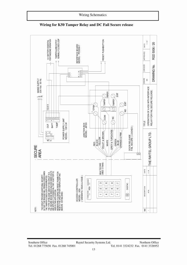
Wiring Schematics
Wiring for K50 Tamper Relay and DC Fail Secure release
DE
SC
RIP
TIO
ND
AT
ET
ITL
ED
RA
WN
CH
EC
KE
DA
PP
RO
VE
DD
AT
E
INIT
IAL
TH
E R
AY
TE
L G
RO
UP
LT
D.
DR
AW
ING
No.
BPM
ISS
ISS
1
RG
D 5
006 / 2
0
OP
ER
AT
ION
OF
A K
50
WIT
H IN
TE
RF
AC
E
RE
LA
Y F
OR
FA
IL S
EC
UR
E R
EL
EA
SE
.
1 -
5 - 9
5
1 -
5 -
95
FU
NC
TIO
NA
CC
ES
SK
50
DIG
ITA
C
12
3
45
6
78
9
0
EX
IT
CO
M
NO
NC
RE
D
BL
AC
K
WH
ITE
YE
LL
OW
GR
EE
NB
LU
E
TA
MP
ER
TA
MP
ER
TA
MP
ER
EX
IT
DO
OR
RE
LE
AS
E
SE
CU
RE
AR
EA
AC
CE
SS
CO
NT
RO
LL
ER
( V
AR
IAN
TS
K
50
S &
K5
0B
)JU
NC
TIO
N B
OX
MO
DE
L -
K5
0
FA
IL S
EC
UR
E (
LO
CK
ED
)
MO
DE
L -
JB
72
0
CA
BLE
2 m
etre
s.M
UL
TIC
OR
E
OR
AN
GE
& P
INK
GR
EY
& T
UR
QU
OIS
E
VIO
LE
T &
BR
OW
N
NC
CNO
INT
ER
FA
CE
BO
AR
DM
OD
EL
- P
C5
00
6/1
OU
T
BA
TT
TA
MP
+ - + -
TA
MP
ER
ALA
RM
OU
TP
UT
NO
RM
ALL
Y C
LOS
ED
LO
OP
PO
WE
R S
UP
PL
Y U
NIT
MO
DE
L -
13
81
LM
13
.8 V
F 2A
L E N
MA
INS
SU
PP
LY
23
0 V
ac
50
Hz.
12 V
BA
TT
ER
Y E
SS
EN
TIA
LFO
R T
IME
ZON
E O
PE
RA
TIO
N
12
Vd
c+
-
+-
RE
SE
T P
US
HB
UT
TO
N
NO
TE
:
TH
E C
IRC
UIT
PR
OV
IDE
S A
DD
ITIO
NA
L S
EC
UR
ITY
TH
E T
AM
PE
R C
LOS
ED
LO
OP
IS IN
TE
RR
UP
TE
D.
IN T
HA
T T
HE
RE
LEA
SE
WIL
L R
EM
AIN
LO
CK
ED
WH
EN
TH
E T
YP
E O
F R
ELE
AS
E U
SE
D IN
TH
IS C
IRC
UIT
IS A
FAIL
SE
CU
RE
DE
VIC
E W
HIC
H U
NLO
CK
S W
HE
N V
OLT
SA
RE
AP
PLI
ED
. IT
IS E
SS
EN
TIA
L T
HA
T A
BA
TT
ER
Y IS
US
ED
IN T
HIS
AP
PLI
CA
TIO
N.
MO
ME
NT
AR
ILY
CLO
SIN
G T
HE
RE
SE
T P
US
HB
UT
TO
N
BE
EN
RE
- E
ST
AB
LIS
HE
D.
RE
SE
TS
TH
E C
IRC
UIT
AFT
ER
TA
MP
ER
LO
OP
HA
S

Southern Office Raytel Security Systems Ltd. Northern Office
Tel. 01268 775656 Fax. 01268 745001 Tel. 0141 3324232 Fax. 0141 3326952
14
Wiring Schematics
Wiring for KA1-KA3 and AC Fail Secure release
DE
SC
RIP
TIO
ND
AT
ET
ITL
ED
RA
WN
CH
EC
KE
DA
PP
RO
VE
DD
AT
E
DR
AW
ING
No
.
ISS
ISS
1IN
ITIA
LK
.H.
12
34
56
SP
EE
CH
UN
ITA
RT
93
0\8
32
56
B1
23
PO
WE
R S
UP
PL
YA
RT
83
2/0
00
24
0V
AC
K5
0 P
CB
CA
LL
PU
SH
BU
TT
ON
S
02
40
01
2
4 7
56
B1
23
4 7
56
B1
23
4 7
12V
0V
CO
M
NC
NO
EX
IT
EX
IT
RE
D
BL
AC
K
BR
OW
N
VIO
LE
T &
GR
EY
&T
UR
QU
OS
E
GR
EE
N
BL
UE
OR
AN
GE
&P
INK
PU
SH
TO
EX
IT
OP
TIO
NA
L E
XIT
BU
TT
ON
06
-01
-96
RA
YT
EL
SE
CU
RIT
Y
SY
ST
EM
S L
TD
.
06
-02
-96
GE
NE
RA
L W
IRIN
G D
IAG
RA
M F
OR
KA
1-K
A3
SY
ST
EM
.
FA
IL S
EC
UR
E R
EL
EA
SE
EN
TR
AN
CE
PA
NE
L M
OD
EL
KA
1 -
KA
3
50
Hz
JUN
CT
ION
BO
XM
OD
EL
- J
B7
20
12
V A
C D
OO
R R
EL
EA
SE
FA
IL S
EC
UR
E (
LO
CK
ED
)
(N\O
OU
TP
UT
)
HA
ND
SE
T 9
00
/00
0
HA
ND
SE
T 9
00
/00
0
HA
ND
SE
T 9
00
/00
0
KE
YC
AL
L W
IRE
S
WIR
ES
C
RO
SS
WIR
ES
C
ON
NE
CT
PU
SH
BU
TT
ON
PI-
00
2-0
1W
ITH
AC
PO
WE
R S
UP
PL
Y A
ND
+-N
O
15
V A
C
C NC
INT
ER
FA
CE
RE
LA
YP
C5
00
6/1

Southern Office Raytel Security Systems Ltd. Northern Office
Tel. 01268 775656 Fax. 01268 745001 Tel. 0141 3324232 Fax. 0141 3326952
15
Wiring Schematics
Wiring for KA1-KA3 and Elvox Gate System
DE
SC
RIP
TIO
ND
AT
ET
ITL
ED
RA
WN
CH
EC
KE
DA
PP
RO
VE
DD
AT
E
DR
AW
ING
No.
ISS
ISS
1IN
ITIA
LK
.H.
12
34
56
SP
EE
CH
UN
ITA
RT
930
\832
56
B1
23
PO
WE
R S
UP
PLY
AR
T 8
32/0
00
240V
AC
K50
PC
B
CA
LLP
US
HB
UT
TO
NS
024
0
012
4 7
56
B1
23
4 7
56
B1
23
4 7
12V
0VC
OM
NC
NO
EX
IT
EX
IT
RE
D
BL
AC
K
BR
OW
NV
IOL
ET
&
GR
EY
&T
UR
QU
OS
E
GR
EE
NB
LU
E
OR
AN
GE
&P
INK
RA
YT
EL S
EC
UR
ITY
SY
ST
EM
S L
TD
.
GE
NE
RA
L W
IRIN
G D
IAG
RA
M F
OR
KA
1-K
A3
SY
ST
EM
.
EN
TR
AN
CE
PA
NE
L M
OD
EL
KA
1 - K
A3
50H
z
JUN
CT
ION
BO
XM
OD
EL
- JB
720
HA
ND
SE
T 9
00/0
00
KE
YC
ALL
WIR
ES
WIR
ES
C
RO
SS
WIR
ES
C
ON
NE
CT
PU
SH
BU
TT
ON
- +
33 32
12V
DC
INP
UT
FRO
M E
LVO
X G
AT
EC
ON
TR
OL
BO
XP
OW
ER
SU
PP
LY
1718
TO
ELV
OX
GA
TE
CO
NT
RO
L
OP
EN
/ C
LOS
E C
OM
MA
ND
BO
X.
TO
INIT
IAT
E T
HE
GA
TE
27-1
1-98
27
-11
-98
PI-00
2-0
1EF
ITT
ED
TO
AN
EL
VO
X A
UT
OM
AT
ICG
AT
E S
YS
TE
M
+-N
O15
V A
C
C NC
INT
ER
FAC
E R
ELA
YP
C50
06/1
HA
ND
SE
T 9
00/0
00
HA
ND
SE
T 9
00/0
00

Southern Office Raytel Security Systems Ltd. Northern Office
Tel. 01268 775656 Fax. 01268 745001 Tel. 0141 3324232 Fax. 0141 3326952
16
Wiring Schematics
Wiring for KA1 – KA3 with DC Fail Safe release
DE
SC
RIP
TIO
ND
AT
ET
ITL
ED
RA
WN
CH
EC
KE
DA
PP
RO
VE
DD
AT
E
DR
AW
ING
No
.
ISS
ISS
1IN
ITIA
LK
.H.
12
34
56
SP
EE
CH
UN
ITA
RT
930
\832
56
B1
23
PO
WE
R S
UP
PLY
AR
T 8
32/0
00
240V
AC
K50
PC
B
CA
LLP
US
HB
UT
TO
NS
024
0
012
4 7
56
B1
23
4 7
56
B1
23
4 7
12V
0V
CO
M
NC
NO
EX
IT
EX
IT
RE
D
BL
AC
K
BR
OW
NV
IOL
ET
&
GR
EY
&T
UR
QU
OS
E
GR
EE
N
BL
UE
OR
AN
GE
&P
INK
PU
SH
TO
EX
IT
OP
TIO
NA
L E
XIT
BU
TT
ON
06-0
1-96
RA
YT
EL
SE
CU
RIT
Y
SY
ST
EM
S L
TD
.
06
-02
-96
GE
NE
RA
L W
IRIN
G D
IAG
RA
M F
OR
KA
1-K
A3
SY
ST
EM
.
EN
TR
AN
CE
PA
NE
L M
OD
EL
KA
1 - K
A3
50H
z
JUN
CT
ION
BO
XM
OD
EL
- JB
720
(N\O
OU
TP
UT
)
HA
ND
SE
T 9
00/0
00
HA
ND
SE
T 9
00/0
00
HA
ND
SE
T 9
00/0
00
KE
YC
ALL
WIR
ES
WIR
ES
CR
OS
SW
IRE
S
CO
NN
EC
T
PU
SH
BU
TT
ON
240V
AC
024
0
012
50H
z
DC
PO
WE
R S
UP
PLY
MO
DE
L 13
81LM
PI-0
02-
02
12V
DC
DO
OR
RE
LEA
SE
FAIL
SA
FE (U
NLO
CK
ED
)
NO
TE
WIT
H D
C F
AIL
SA
FE
RE
LE
AS
E
FAIL
SA
FE L
OC
KS
CO
NN
EC
T0V
AN
D N
C A
S S
HO
WN
FOR
US
E W
ITH
FA
IL S
EC
UR
E L
OC
KS
CO
NN
EC
T L
OC
K T
O 0
V A
ND
NO
+-N
O
15V
AC
C NC
INT
ER
FAC
E R
ELA
YP
C50
06/1

Southern Office Raytel Security Systems Ltd. Northern Office
Tel. 01268 775656 Fax. 01268 745001 Tel. 0141 3324232 Fax. 0141 3326952
17
Wiring Schematics
Wiring for KV1 System and AC Fail Secure release
DE
SC
RIP
TIO
ND
AT
ET
ITL
ED
RA
WN
CH
EC
KE
DA
PP
RO
VE
DD
AT
E
DR
AW
ING
No.
ISS
ISS
INIT
IAL
K.H
.R
AY
TE
L S
EC
UR
ITY
SY
ST
EM
S L
TD
.A
22-0
5-96
22-0
5-96
PI-0
07-0
1
PO
WE
R S
UP
PL
Y
24
0V
AC
K5
0 P
CB
CA
LL
PU
SH
0 01
2V
0V
CO
M
NC
NO
EX
IT
EX
IT
RE
D
BL
AC
K
BR
OW
NV
IOL
ET
&
GR
EY
&T
UR
QU
OS
EG
RE
EN
BL
UE
OR
AN
GE
&P
INK
PU
SH
TO
EX
IT
OP
TIO
NA
L E
XIT
BU
TT
ON
50
Hz
JUN
CT
ION
BO
XM
OD
EL
- J
B7
20
12
V A
C D
OO
R R
EL
EA
SE
FA
IL S
EC
UR
E (
LO
CK
ED
)
(N\O
OU
TP
UT
)
MO
NIT
OR
A
RT
54
79
/01
M1 2 3 4 5 6 7 8 9 10
11
12
V1
V2
AR
T 8
32
/03
0
12
24
0
M*
NO
TE
*C
ON
NE
CT
75
-OH
M R
ES
IST
OR
BE
TW
EE
N M
AN
D V
27
5 O
HM
CA
ME
RA
UN
IT5
47
9/0
1T
76
54
32
1V
M
YE
LL
OW
RE
D
CO
AX
YE
LL
OW
RE
D
BU
TT
ON
CA
BL
E A
RT
2/0
63
K5
0 C
AB
LE
+-N
O1
5V
AC
C NC
INT
ER
FA
CE
RE
LA
YP
C5
00
6/1
12
V0
V
CO
M
NC
NO
EX
IT
EX
IT
RE
D
BL
AC
K
BR
OW
NV
IOL
ET
&
GR
EY
&T
UR
QU
OS
E
GR
EE
NB
LU
E
OR
AN
GE
&P
INK
JU
NC
TIO
N B
OX
MO
DE
L -
JB
72
0
FR
OM
K5
0
FR
OM
EX
IT P
US
HA
ND
IN
TE
RF
AC
E R
EL
AY
DO
OR
RE
LE
AS
E1
2V
DC - +
FR
OM
EX
TE
RN
AL
12
V D
C P
SU
(eg
MO
DE
L 1
38
ILM
)
FO
R F
AIL
SE
CU
RE
LO
CK
S (
LO
CK
ED
)C
ON
NE
CT
TO
NO
CO
NT
AC
TF
OR
FA
IL S
AF
E L
OC
KS
(O
PE
N)
CO
NN
EC
T T
O N
C C
ON
TA
CT
GE
NE
RA
L W
IRIN
G D
IAG
RA
M
FO
R K
V1 S
YS
TE
M
EN
SU
RE
PS
U A
RT
83
2/0
30
IS
LO
CA
TE
D A
S C
LO
SE
TO
TH
EM
ON
ITO
R A
S P
OS
SIB
LE
SU
PP
LIE
D C
AB
LE
IS
FO
R R
UN
S U
P T
O 3
0m
US
E C
OA
XIA
L C
AB
LE
TY
PE
RG
59
AN
DC
AB
LE
OF
1m
m C
SA
.
EN
TR
AN
CE
PA
NE
L M
OD
EL
KV
1
VA
RIA
NT
FO
R O
PE
RA
TIO
N O
F D
C L
OC
KS
FO
R C
AB
LE
RU
NS
UP
TO
10
0m

Southern Office Raytel Security Systems Ltd. Northern Office
Tel. 01268 775656 Fax. 01268 745001 Tel. 0141 3324232 Fax. 0141 3326952
18
Wiring Schematics
Wiring for KV1 – KV3 and AC Fail Secure release
DE
SC
RIP
TIO
ND
AT
ET
ITLE
DR
AW
NC
HE
CK
ED
AP
PR
OV
ED
DA
TE
DR
AW
ING
No
.
ISS
ISS
INIT
IAL
K.H
.R
AY
TE
L S
EC
UR
ITY
SY
ST
EM
S L
TD
.
22-
05-9
6
K50 P
CB
CA
LL
PU
SH
0V
CO
M
NC
NO
EX
IT
EX
IT
RE
D
BLA
CK
BR
OW
NV
IOL
ET
&
GR
EY
&T
UR
QU
OS
EG
RE
EN
BLU
E
OR
AN
GE
&P
INK
PU
SH
TO
EX
IT
OP
TIO
NA
L E
XIT
BU
TT
ON
JUN
CT
ION
BO
XM
OD
EL -
JB
720
FA
IL S
EC
UR
E (
LO
CK
ED
)
(N\O
OU
TP
UT
)
1 2 3 4 5 6 7V1
V2
CA
ME
RA
UN
IT VM
K50
CA
BLE
+-N
O15V
AC
C NC
INT
ER
FA
CE
RE
LA
YP
C5006/1
GE
NE
RA
L W
IRIN
G D
IAG
RA
M
EN
TR
AN
CE
PA
NE
L M
OD
EL K
V1
+T
-8
76
43
554/H
50
M 8 9 10 11
12
V
PS
U A
RT
5680
A B
1 2 3 4 5 6 7V1
V2M 8 9 1
0 11
12
IN T
HE
A P
OS
ITIO
NE
NS
UR
E A
-B S
WIT
CH
IS
PR
I
240V
AC
M1V
1V2
M2
C1 C
21
23
-+
S6
78
-+
TA
M15
0S
1C
1
12
35
69
MO
NIT
OR
CA
BLE
RIS
ER
V1
V2M
CO
NN
EC
T 7
5 O
HM
RE
SIS
TO
RT
O T
HE
LA
ST
MO
NIT
OR
BE
TW
EE
N T
ER
MIN
ALS
V2-M
BU
TT
ON
S
15
V
8
SE
E V
AR
IAN
T F
OR
DC
LO
CK
SO
N D
RA
WIN
G P
I-007
-01
EN
SU
RE
LO
CK
TIM
E (
P3)
IS S
ET
TO
MIN
IMU
M
MO
NIT
OR
A
RT
5601/0
00
MO
NIT
OR
A
RT
5601/0
00
21-0
1-97
FO
R A
C L
OC
K O
PE
RA
TIO
N
12V
DC
DO
OR
RE
LE
AS
E
FO
R K
V5
68
0 1
, 2
& 3
KIT
SR
GD
50
13
/ 6
5
1

Southern Office Raytel Security Systems Ltd. Northern Office
Tel. 01268 775656 Fax. 01268 745001 Tel. 0141 3324232 Fax. 0141 3326952
19
Quick Programming Guide
Quick Programming Guide.
The K50 is programmed using the keyboard. Entering the six digit Master
code accesses the programming mode. The following paragraphs cover initial
programming for a basic access control system. To access the more advanced
features of the K50 please refer to the Advanced Programming Guide section.
Programming a code
When the K50 is delivered there are no user codes in memory. The following
instructions show how to enter a single user code for standard twenty-four
hour operation.
Action Indication Notes Enter six Digit
Master Code
Found on the inside cover of
this manual
Press the # key Red LED lights accompanied by a
long audible tone
Master code accepted
Press the # key Red LED begins to flash every ½
second
Ready to accept a user code
Enter a user code Code can be four to eight
digits in length
Press the # key Red LED begins to flash every
second
The code has been accepted
Press the # key Red LED steady, long audible tone,
Red LED turns off
Exit function and return to
normal operation
Ensure that there is less than four seconds delay between each key press. This
prevents the Code Entry Timer from registering an invalid code.
Deleting a code
The following instructions show how to delete a single user code.
Action Indication Notes Enter six Digit
Master Code
Found on the inside cover of
this manual
Press the # key Red LED lights accompanied by a
long audible tone
Master code accepted
Press 9 followed
by the # key
Red LED begins to flash every ½
second
Delete function entered
Enter the user
code to delete
followed by the #
key
Red LED begins to flash every
second
If the code does not exist the
K50 gives a two-second
audible tone with steady red
LED.
Press the # key Two long audible tones Red LED
off while tone sounds.
The code has been deleted.
Note: To escape without
deleting the code press the *
key instead of the # key. The
K50 will give a two-second
audible tone with steady red
LED.
Press the * key Red LED steady, long audible tone,
Red LED turns off
Exit function and return to
normal operation
Ensure that there is less than four seconds delay between each key press. This
prevents the Code Entry Timer from registering an invalid code.

Southern Office Raytel Security Systems Ltd. Northern Office
Tel. 01268 775656 Fax. 01268 745001 Tel. 0141 3324232 Fax. 0141 3326952
20
Quick Programming Guide
Setting the Lock Relay Time
The lock relay can be set to operate from one to ninety nine seconds when a
valid user code is entered or the exit push button is operated. The factory
setting for the relay time is four seconds. The following instructions show
how to adjust this time if required.
Action Indication Notes Enter six Digit
Master Code
Found on the inside cover of
this manual
Press the # key Red LED lights accompanied by a
long audible tone
Master code accepted
Press 1 followed
by the # key
Red LED begins to flash every ½
second
Set relay time function entered
Enter the required
lock time
(1 – 99 seconds)
followed by the #
key
Relay operates for the number of
seconds entered accompanied by
the Red LED and Green LED lit
and an audible tone
Should the relay time require
adjusting enter the new lock
time before proceeding to the
next step. This can be
repeated as often as required.
Press the # key Two long audible tones Red LED
off while tone sounds.
The lock time has been set
Press the * key Red LED steady, long audible tone,
Red LED turns off
Exit function and return to
normal operation
Ensure that there is less than four seconds delay between each key press. This
prevents the Code Entry Timer from registering an invalid code.
Activating the K50 self test mode
The K50 can test the internal functions and the operation of each button on the
keypad by entering the self-test mode.
Action Indication Notes Turn off the
power to the K50
Hold down the
# and * keys
Return power to
the K50
The Red and Green LED’s will
flash accompanied by an audible
bleep.
Ensure the # and * keys
remain held down
After the fifth
bleep Release the
# and * keys
The unit commences the self-test.
See K50 test sequence for details of
test results.
Releasing the keys before the
fifth bleep exits to normal
mode.
Releasing the keys between
the fifth and ninth bleep enters
self-test mode.
WARNING: If the keys are
not released before the tenth
bleep the K50 will enter
Master Reset this will clear all
the programmed codes.
See the Advanced
Programming section for
details.

Southern Office Raytel Security Systems Ltd. Northern Office
Tel. 01268 775656 Fax. 01268 745001 Tel. 0141 3324232 Fax. 0141 3326952
21
Quick Programming Guide
K50 Test sequence
After entering Self-test the K50 will run through the following sequence of
tests.
1. Red LED flashes twice.
2. Green LED flashes twice.
3. Sounder bleeps twice.
4. Lock Relay operates twice.
5. The K50 tests internal functions. Should a fault be detected the test
sequence will end and the Red and Green LED’s will flash. If no faults
are found the Red and Green LED will illuminate accompanied by a
single audible tone.
6. The K50 is now ready to test the keypad. Press each keypad button in
turn.
7. Press button 1 both LED’s will flash once accompanied by an audible
tone to indicate the button is functioning correctly.
8. Press button 2 both LED’s will flash twice accompanied by an audible
tone to indicate the button is functioning correctly.
9. Press buttons 3 to 9 both LED’s will flash, for the number of times
corresponding to the button pressed, accompanied by an audible tone
to indicate the button is functioning correctly.
10. Press button 0 both LED’s will flash ten times accompanied by an
audible tone to indicate the button is functioning correctly.
11. Press button * both LED’s will flash eleven times accompanied by an
audible tone to indicate the button is functioning correctly.
12. Press the exit button both LED’s will flash twelve times accompanied
by an audible tone to indicate the button is functioning correctly.
13. Press button # both LED’s will give three long flashes accompanied by
an audible tone. The unit then returns to normal mode.
A self-test can be performed at any time without affecting any programmed
settings. Care should be taken however to ensure a Master reset is not
performed, as this would clear all pre programmed settings.

Southern Office Raytel Security Systems Ltd. Northern Office
Tel. 01268 775656 Fax. 01268 745001 Tel. 0141 3324232 Fax. 0141 3326952
22
Advanced Programming Guide
Advanced Programming Guide.
Performing a Master Reset
The Master Reset will perform the following tasks: -
Clear all user codes.
Reinstate the Factory master code.
Clear all time zone functions and settings
Reset sounder operation
Reset relay time to four seconds
Action Indication Notes Turn off the
power to the K50
Hold down the
# and * keys
Return power to
the K50
The Red and Green LED’s will
flash accompanied by an audible
bleep.
Ensure the # and * keys
remain held down
After the tenth
bleep Release the
# and * keys
The unit performs a Master Reset. Releasing the keys before the
fifth bleep exits to normal
mode.
Releasing the keys between
the fifth and ninth bleep enters
self-test mode. See previous
section for details.

Southern Office Raytel Security Systems Ltd. Northern Office
Tel. 01268 775656 Fax. 01268 745001 Tel. 0141 3324232 Fax. 0141 3326952
23
Advanced Programming Guide
Setting the Lock Relay Time
The lock relay can be programmed to operate from one to ninety nine seconds
when a valid user code is entered or the exit push button is operated.
When the K50 is supplied the lock relay time is set at four seconds.
To program the Lock Relay Time
Action Indication Notes Enter six Digit
Master Code
Found on the inside cover of
this manual
Press the # key Red LED lights accompanied by a
long audible tone
Master code accepted
Press 1 followed
by the # key
Red LED begins to flash every ½
second
Set relay time function entered
Enter the required
lock time
(1 – 99 seconds)
followed by the #
key
Relay operates for the number of
seconds entered accompanied by
the Red LED and Green LED lit
and an audible tone
Should the relay time require
adjusting enter the new lock
time before proceeding to the
next step. This can be
repeated as often as required.
Press the # key Two long audible tones Red LED
off while tone sounds.
The lock time has been set
Press the * key Red LED steady, long audible tone,
Red LED turns off
Exit function and return to
normal operation
Ensure that there is less than four seconds delay between each key press. This
prevents the Code Entry Timer from registering an invalid code.

Southern Office Raytel Security Systems Ltd. Northern Office
Tel. 01268 775656 Fax. 01268 745001 Tel. 0141 3324232 Fax. 0141 3326952
24
Advanced Programming Guide
Installing User Codes
The K50 can be programmed with a maximum of fifty user codes of four to
eight digits in length. These user codes can be programmed to operate in
twenty four hour mode, assigned to one of the five timed access periods,
service mode or latch mode.
User codes assigned to access periods 1 to 5 will not function until the clock
and time periods have been set. (See Setting the clock, page 25, and
Programming time zones, page 30, for details of how to do this.) User codes assigned to access period 6 are used to enter Service Mode. User
codes assigned to access period 7 are used to enter Latch Mode.
When the K50 is delivered there are no user codes in memory.
Note: If the first four digits of the code being entered is the same as an existing
code then the new code will overwrite the existing code.
To Install Codes
Action Indication Notes Enter six Digit
Master Code
Found on the inside cover of
this manual
Press the # key Red LED lights accompanied by a
long audible tone
Master code accepted
Press 2 followed
by the # key
Red LED begins to flash every ½
second
Ready to install code
Enter the User
Code
Code can be four to eight
digits in length
Press the # key Red LED flashes every second The code has been accepted
Press the # key
for 24 hour
operation
Or For Timed
operation press
key 1-7 followed
by the # key
Red LED flashes twice
accompanied by a long audible tone
1 to 5 are timed access periods
See Programming time
zones, page 30, for details.
6 is service mode, see page 26
for details of use.
7 is latch mode, see page 27
for details of use.
To add additional
codes repeat
instructions from
highlighted
section inclusive.
OR Press the * key to
exit programming
mode.
Red LED steady, long audible tone,
Red LED turns off
Exit function and return to
normal operation
Ensure that there is less than four seconds delay between each key press. This
prevents the Code Entry Timer from registering an invalid code.

Southern Office Raytel Security Systems Ltd. Northern Office
Tel. 01268 775656 Fax. 01268 745001 Tel. 0141 3324232 Fax. 0141 3326952
25
Advanced Programming Guide
Setting the Clock
The clock must be set to enable the time zone facility. (See Programming time
zones, page 30 and Installing a user code, page 24 for details of how to set
time zones and assign user codes.)
When the K50 is delivered the clock is disabled (set to 00hr 00min). After
programming, should it be desirable, the clock can be disabled by setting the
clock time to 00hr 00min, this has the effect of stopping the clock and
disabling all time zone operations.
Note: The K50 clock is not battery backed. If time zone operation is to
be maintained in the event of mains failure a 12V DC supply with a
battery standby facility should be used.
If a power failure occurs after the clock has been set, when the power is restored
the K50 will bleep three times to indicate the time may require resetting. This
will be repeated every minute until the time is reprogrammed or the clock
function is disabled by setting the clock time to 00hr 00min.
To Set the Time
Action Indication Notes Enter six Digit
Master Code
Found on the inside cover of
this manual
Press the # key Red LED lights accompanied by a
long audible tone
Master code accepted
Press 3 followed
by the # key
Red LED begins to flash every ½
second
Ready to Set the time
Enter the correct
time
Time is to be entered using
24hr format. E.g. 9.30 AM
would be entered 0930 while
9.30 PM would be entered
2130.
Press the # key Red LED flashes every second The time has been accepted
Press the # key Red LED flashes twice
accompanied by a long audible tone
The time has been set
Press the * key Red LED steady, long audible tone,
Red LED turns off
Exit function and return to
normal operation
Ensure that there is less than four seconds delay between each key press. This
prevents the Code Entry Timer from registering an invalid code.
Southern Office Raytel Security Systems Ltd. Northern Office
Tel. 01268 775656 Fax. 01268 745001 Tel. 0141 3324232 Fax. 0141 3326952
26
Advanced Programming Guide
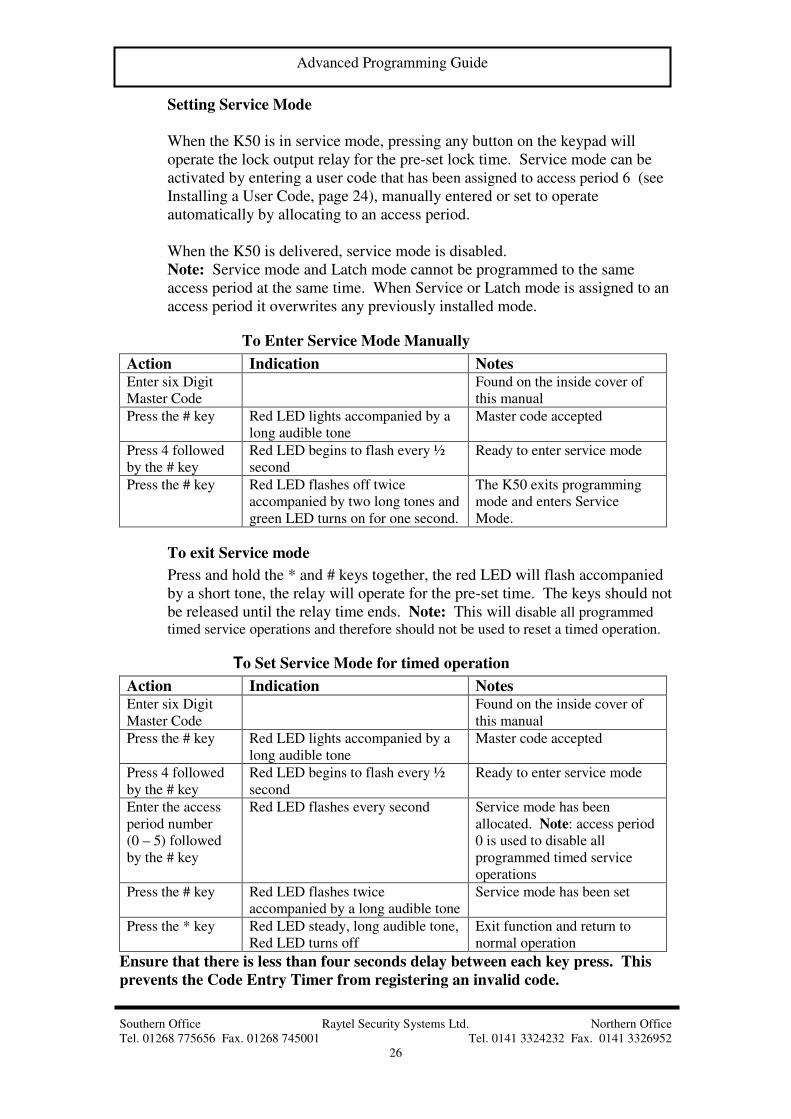
Setting Service Mode
When the K50 is in service mode, pressing any button on the keypad will
operate the lock output relay for the pre-set lock time. Service mode can be
activated by entering a user code that has been assigned to access period 6 (see
Installing a User Code, page 24), manually entered or set to operate
automatically by allocating to an access period.
When the K50 is delivered, service mode is disabled.
Note: Service mode and Latch mode cannot be programmed to the same
access period at the same time. When Service or Latch mode is assigned to an
access period it overwrites any previously installed mode.
To Enter Service Mode Manually
Action Indication Notes Enter six Digit
Master Code
Found on the inside cover of
this manual
Press the # key Red LED lights accompanied by a
long audible tone
Master code accepted
Press 4 followed
by the # key
Red LED begins to flash every ½
second
Ready to enter service mode
Press the # key Red LED flashes off twice
accompanied by two long tones and
green LED turns on for one second.
The K50 exits programming
mode and enters Service
Mode.
To exit Service mode
Press and hold the * and # keys together, the red LED will flash accompanied
by a short tone, the relay will operate for the pre-set time. The keys should not
be released until the relay time ends. Note: This will disable all programmed
timed service operations and therefore should not be used to reset a timed operation.
To Set Service Mode for timed operation
Action Indication Notes Enter six Digit
Master Code
Found on the inside cover of
this manual
Press the # key Red LED lights accompanied by a
long audible tone
Master code accepted
Press 4 followed
by the # key
Red LED begins to flash every ½
second
Ready to enter service mode
Enter the access
period number
(0 – 5) followed
by the # key
Red LED flashes every second Service mode has been
allocated. Note: access period
0 is used to disable all
programmed timed service
operations
Press the # key Red LED flashes twice
accompanied by a long audible tone
Service mode has been set
Press the * key Red LED steady, long audible tone,
Red LED turns off
Exit function and return to
normal operation
Ensure that there is less than four seconds delay between each key press. This
prevents the Code Entry Timer from registering an invalid code.

Southern Office Raytel Security Systems Ltd. Northern Office
Tel. 01268 775656 Fax. 01268 745001 Tel. 0141 3324232 Fax. 0141 3326952
27
Advanced Programming Guide
Setting Latch Mode
Latch mode is used to latch the lock output relay on. Latch mode can be
activated by entering a user code that has been assigned to access period 7 (see
Installing a User Code, page 24), manually entered or set to operate
automatically by allocating to an access period.
When the K50 is delivered latch mode is disabled.
Note1: The exit push button is disabled during latch mode operation.
Note2: Latch mode and Service mode cannot be programmed to the same
access period at the same time. When Latch or Service mode is assigned to an
access period it overwrites any previously installed mode.
To Enter Latch Mode Manually
Action Indication Notes Enter six Digit
Master Code
Found on the inside cover of
this manual
Press the # key Red LED lights accompanied by a
long audible tone
Master code accepted
Press 5 followed
by the # key
Red LED begins to flash every ½
second
Ready to enter latch mode
Press the # key Red LED flashes off twice with two
long tones and the green LED turns
on during relay operation.
The K50 exits programming
mode and enters latch Mode.
Press the * key Red LED steady, long audible tone,
Red LED turns off
Exit function and return to
normal operation
To exit Latch mode
Press the # key or enter a valid user code.
Note: Using the # key to exit will disable all programmed timed latch operations
and therefore should not be used to reset a timed operation. When a user code is used
the sounder and green LED will operate for the pre-set relay time before exiting.
To Set Latch Mode for timed operation
Action Indication Notes Enter six Digit
Master Code
Found on the inside cover of
this manual
Press the # key Red LED lights accompanied by a
long audible tone
Master code accepted
Press 5 followed
by the # key
Red LED begins to flash every ½
second
Ready to enter latch mode
Enter the access
period number
(0 – 5) followed
by the # key
Red LED flashes every second Latch mode has been set.
Note: access period 0 is used
to disable all programmed
timed latch operations
Press the # key Red LED flashes twice
accompanied by a long audible tone
Latch mode has been set
Press the * key Red LED steady, long audible tone,
Red LED turns off
Exit function and return to
normal operation
Ensure that there is less than four seconds delay between each key press. This
prevents the Code Entry Timer from registering an invalid code.
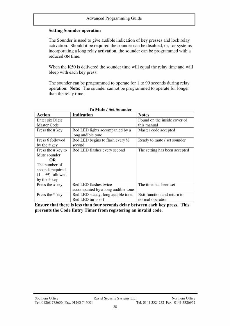
Southern Office Raytel Security Systems Ltd. Northern Office
Tel. 01268 775656 Fax. 01268 745001 Tel. 0141 3324232 Fax. 0141 3326952
28
Advanced Programming Guide
Setting Sounder operation
The Sounder is used to give audible indication of key presses and lock relay
activation. Should it be required the sounder can be disabled, or, for systems
incorporating a long relay activation, the sounder can be programmed with a
reduced ON time.
When the K50 is delivered the sounder time will equal the relay time and will
bleep with each key press.
The sounder can be programmed to operate for 1 to 99 seconds during relay
operation. Note: The sounder cannot be programmed to operate for longer
than the relay time.
To Mute / Set Sounder
Action Indication Notes Enter six Digit
Master Code
Found on the inside cover of
this manual
Press the # key Red LED lights accompanied by a
long audible tone
Master code accepted
Press 6 followed
by the # key
Red LED begins to flash every ½
second
Ready to mute / set sounder
Press the # key to
Mute sounder
OR The number of
seconds required
(1 – 99) followed
by the # key
Red LED flashes every second The setting has been accepted
Press the # key Red LED flashes twice
accompanied by a long audible tone
The time has been set
Press the * key Red LED steady, long audible tone,
Red LED turns off
Exit function and return to
normal operation
Ensure that there is less than four seconds delay between each key press. This
prevents the Code Entry Timer from registering an invalid code.

Southern Office Raytel Security Systems Ltd. Northern Office
Tel. 01268 775656 Fax. 01268 745001 Tel. 0141 3324232 Fax. 0141 3326952
29
Advanced Programming Guide
Code Capacity Check
This function is used to check the number of User Codes programmed into the
K50. When initiated the K50 will give a short audible tone for each User
Code programmed.
Code Capacity Check
Action Indication Notes Enter six Digit
Master Code
Found on the inside cover of
this manual
Press the # key Red LED lights accompanied by a
long audible tone
Master code accepted
Press 7 followed
by the # key
Red LED begins to flash every ½
second
Code capacity check entered
Press the # key
when ready to
count.
Red LED flashes accompanied by a
short tone for each User Code
programmed in the K50.
Each tone indicates one
programmed code.
Red LED flashes twice
accompanied by a long audible tone
Indicates that no more user
codes remain to be counted.
Press the * key Red LED steady, long audible tone,
Red LED turns off
Exit function and return to
normal operation
Ensure that there is less than four seconds delay between each key press. This
prevents the Code Entry Timer from registering an invalid code.

Southern Office Raytel Security Systems Ltd. Northern Office
Tel. 01268 775656 Fax. 01268 745001 Tel. 0141 3324232 Fax. 0141 3326952
30
Advanced Programming Guide
Access Levels and Time Zones
Up to two sets of time zone markers (Start1, End1 – Start2, End2) may be
programmed into the controller to give a maximum of six separate access
levels covering six specific time zones during a 24 hour period. This allows
different codes to be assigned to any one of the six time zones. The method
for assigning access levels to codes can be found under ”Installing User
Codes” on page 24.
The following table shows the way in which the time zone markers are used to
create the six different access levels. 00.00 24.00
hrs Start1 End1 Start2 End2 hrs Access
Level 0
No markers
Default Setting
Access Zone 0 Active, Unlimited Access
Access
Zone 1
active
Level 1
Level 2
Markers
Start1 – End1 Access
Zone 2
active
Access Zone 2 active
Access
Zone 3
active
Level 3
Level 4
Markers
Start2 – End2 Access Zone 4 active Access
Zone 4
active
Level 5 Markers
Start1 – End2
Access Zone 5 active
Level 0 does not require any time zone markers to be set and is the
default setting for all codes. Codes assigned to this level will
have unlimited access during the 24 hour period. (Zone 0).
Level 1 is the time zone commencing Start1 and ending with End1, any
codes assigned to level 1 will only have access during this
period. (Zone 1).
Level 2 is the time zone commencing End1 and ending with Start1, any
codes assigned to level 2 will only have access during this
period. (Zone 2).
Level 3 is the time zone commencing Start2 and ending with End2, any
codes assigned to level 3 will only have access during this
period. (Zone 3).
Level 4 is the time zone commencing End2 and ending with Start2, any
codes assigned to level 4 will only have access during this
period. (Zone 4).
Level 5 is the time zone commencing Start1 and ending with End2, any
codes assigned to level 5 will only have access during this
period. (Zone 5).

Southern Office Raytel Security Systems Ltd. Northern Office
Tel. 01268 775656 Fax. 01268 745001 Tel. 0141 3324232 Fax. 0141 3326952
31
Advanced Programming Guide
It should be noted that once time zone markers have been set for one level,
they remain fixed in those positions for the other levels.
For user codes assigned to access periods to operate correctly the unit clock
must be set. Refer to setting the clock, page 25 for details on setting the
correct time. By setting time zone markers Start1 and End1, access levels 1
and 2 are available for use. Access levels 3, 4 and 5 will not be available until
time zone markers Start2 and End2 have been programmed.
Programming Time Zone markers
Action Indication Notes Enter six Digit
Master Code
Found on the inside cover of
this manual
Press the # key Red LED lights accompanied by a
long audible tone
Master code accepted
Press 8 followed
by the # key
Red LED begins to flash every ½
second
Ready to program time zones
Enter time zone 1
start time (Start1)
in 24 hour format
followed by the #
key. ( E.g. 0900#
for 9 AM)
Red LED flashes every second Start time has been accepted
Enter time zone 1
stop time (End1)
in 24 hour format
followed by the #
key. ( E.g. 1130#
for 11.30 AM)
Red LED flashes every 1½ second Stop time has been accepted
Skip the next two operations if time zone 2 is not required
Enter time zone 2
start time (Start2)
in 24 hour format
followed by the #
key. ( E.g. 1600#
for 4.00 PM)
Red LED flashes every 2 seconds Start time has been accepted
Enter time zone 2
stop time (End2)
in 24 hour format
followed by the #
key. ( E.g. 1830#
for 6.30 PM)
Red LED flashes every 2½ seconds Stop time has been accepted
Press the # key Red LED flashes twice
accompanied by a long audible tone
The time zones have been set
Press the * key Red LED steady, long audible tone,
Red LED turns off
Exit function and return to
normal operation
Ensure that there is less than four seconds delay between each key press. This
prevents the Code Entry Timer from registering an invalid code.
To deactivate time zones programme the start and stop times to 0000.

Southern Office Raytel Security Systems Ltd. Northern Office
Tel. 01268 775656 Fax. 01268 745001 Tel. 0141 3324232 Fax. 0141 3326952
32
Advanced Programming Guide
Deleting a single user code
The following instructions show how to delete a single user code.
Note: The User Master Code cannot be deleted with this function.
Action Indication Notes Enter six Digit
Master Code
Found on the inside cover of
this manual
Press the # key Red LED lights accompanied by a
long audible tone
Master code accepted
Press 9 followed
by the # key
Red LED begins to flash every ½
second
Delete function entered
Enter the user
code to delete
followed by the #
key
Red LED begins to flash every
second
If the code does not exist the
K50 gives a two-second
audible tone with steady red
LED.
Press the # key Two long audible tones Red LED
off while tone sounds.
The code has been deleted.
Note: To escape without
deleting the code press the *
key instead of the # key. The
K50 will give a two-second
audible tone with steady red
LED.
Press the * key Red LED steady, long audible tone,
Red LED turns off
Exit function and return to
normal operation
Ensure that there is less than four seconds delay between each key press. This
prevents the Code Entry Timer from registering an invalid code.

Southern Office Raytel Security Systems Ltd. Northern Office
Tel. 01268 775656 Fax. 01268 745001 Tel. 0141 3324232 Fax. 0141 3326952
33
Advanced Programming Guide
Deleting ALL user codes
This function will delete all user codes. All other programmed parameters and
the Master Code will not be affected.
Action Indication Notes Enter six Digit
Master Code
Found on the inside cover of
this manual
Press the # key Red LED lights accompanied by a
long audible tone
Master code accepted
Press 10 followed
by the # key
Red LED begins to flash every ½
second
Delete function entered
Press the # key Two long audible tones Red LED
off while tone sounds.
Warning: This will delete all
programmed user codes.
Note: To escape without
deleting the code press the *
key instead of the # key. The
K50 will give a two-second
audible tone with steady red
LED.
Press the * key Red LED steady, long audible tone,
Red LED turns off
Exit function and return to
normal operation
Ensure that there is less than four seconds delay between each key press. This
prevents the Code Entry Timer from registering an invalid code.

Southern Office Raytel Security Systems Ltd. Northern Office
Tel. 01268 775656 Fax. 01268 745001 Tel. 0141 3324232 Fax. 0141 3326952
34
Advanced Programming Guide
Changing the Master Code
For increased security the Factory Master Code can be reprogrammed to a
User Master Code. The User Master Code can be reprogrammed as often as
required.
Note: A User Master Code cannot be programmed if its first four digits are
the same as a current User Code, this also means that a user code cannot be
programmed if its first four digits are the same as the current Master Code.
Please note there is no function 11.
Action Indication Notes Enter six Digit
Master Code
Found on the inside cover of
this manual
Press the # key Red LED lights accompanied by a
long audible tone
Master code accepted
Press 12 followed
by the # key
Red LED begins to flash every ½
second
Ready to reprogram the Master
Code
Enter the 6 digit
Master code
followed by the #
key.
Red LED begins to flash every
second
The new Master Code has
been accepted.
Press the # key Two long audible tones Red LED
off while tone sounds.
The new Master Code has
been programmed.
Press the * key Red LED steady, long audible tone,
Red LED turns off
Exit function and return to
normal operation
Ensure that there is less than four seconds delay between each key press. This
prevents the Code Entry Timer from registering an invalid code.

Southern Office Raytel Security Systems Ltd. Northern Office
Tel. 01268 775656 Fax. 01268 745001 Tel. 0141 3324232 Fax. 0141 3326952
35
Technical Information
Technical Information
Power Supply - 10 – 16V AC, 10 – 28V DC.
Power Consumption - 9 mA quiescent, 80 mA during relay
operation.
Lock output - Volt free changeover. Contact rating
50V AC / DC 1.5A inductive.
Tamper Switch - Volt free normally open contact.
Exit Button - Requires normally open switch input.
Code Memory - Permanent retention in E2PROM.
Clock Memory - There is no internal battery. The clock
will require resetting if power is lost.
Power Failure - If the clock has been programmed the
Indication K50 will emit three audible bleeps every
minute after power is restored. To turn
this off set the correct time or disable the
clock.
Connections - Unit is supplied with two metres of
twelve core cable.
Visual Indications - Red LED to indicate keypad entry and
programming status. Green LED to
indicate relay operation.
Dust/Water protection - IP54.
Dimensions (mm)
Model H W D Main Material
K50 136 80 32 ABS housing UL 94-5v
K50 S 146 86 - Stainless Steel grade BS1449/304
K50 B 146 86 - Polished Brass grade BS2870/cz120
K50 C 146 86 30 Stainless Steel grade BS1449/304
K50CB 146 86 30 Polished Brass grade BS2870/cz120
FB146 (for K50S/B) 135 75 35 Zinc Plated Steel, Flush box
SB146/1 (for K50S/B) 151 92 32 Coated Steel / Paint finish, Surface box
KA series (Audio entry panel with keypad) Please contact the office for details
KV series (Video entry panel with keypad) Please contact the office for details

Southern Office Raytel Security Systems Ltd. Northern Office
Tel. 01268 775656 Fax. 01268 745001 Tel. 0141 3324232 Fax. 0141 3326952
36
Technical Information
Programming Summary Table
Steps 1 2 3 4 5 6 7 8
Description Master
code Function No. 1st Data 2nd Data 3rd Data 4th Data Confirm Escape
Enter Program
mode
Master code
#
Single User
Code
Master code
# # User Code # # AUTO
Relay time Master code
# 1# Time(seconds)# # *
Install Codes
(24 hour)
Master code
# 2# User Code # # *
Install Codes
(with time zone)
Master code
# 2# User Code # Time Zone # *
Set Clock Master code
# 3# Time (24Hr) # # *
Services Mode Master code
# 4# Time Zone # # *
Latch Mode Master code
# 5# Time Zone # # *
Sounder Time Master code
# 6# Time(seconds)# # *
Code Capacity Master code
# 7# # *
Time Settings
(T1 and T2)
Master code
# 8# Time 1 # Time 2 # # *
Time Settings
(T1 to T4)
Master code
# 8# Time 1 # Time 2 # Time 3 # Time 4 # # *
Delete Codes Master code
# 9#
Code to Delete
# # *
Delete All User
Codes
Master code
# 10# # *
Reprogram
Master code
Current
Master
Code #
12# New 6 digit
Master Code # # *
Escape Program
Mode *