Embed Size (px)
Citation preview

Quickie® S-646/S-646 HDS-646SE/S-646SE HD
User
Instruction
Manual &
WarrantySUPPLIER:THIS MANUAL MUST BEGIVEN TO THE RIDER OFTHIS WHEELCHAIR.
RIDER:BEFORE USING THISWHEELCHAIR READ THISENTIRE MANUAL AND SAVEFOR FUTURE REFERENCE.
930477 Rev. C
I . I n t r o d u c t i o n 3
SUNRISE LISTENS
Thank you for choosing a Quickie wheelchair. We want to hear your questions or comments about this manual, the safety and reliability of your chair, and the serviceyou receive from your Sunrise supplier. Please feel free to write or call us at theaddress and telephone number below:
SUNRISE MEDICALCustomer Service Department7477 East Dry Creek ParkwayLongmont, Colorado 80503(303) 218-4500 or (800) 333-4000
FOR ANSWERS TO YOUR QUESTIONSYour authorized supplier knows your wheelchair best, and can answer most of yourquestions about chair safety, use and maintenance. For future reference, fill in the following:
Supplier: ______________________________________________________________________________
Address: _______________________________________________________________________________
______________________________________________________________________________________
Telephone: _____________________________________________________________________________
Serial #: _______________________________________ Date/Purchased: ________________________

930477 Rev. C
I I . T a b l e o f C o n t e n t s 5
VIII. TIPS FOR ATTENDANTS........................................................................... 26A. To Climb a Curb or Single Step ............................................................ 26B. To Descend a Curb or Single Step......................................................... 26
IX. SET UP, ADJUSTMENT & USE................................................................... 27A. Notes............................................................................................... 27B. Tools You Will Need ........................................................................... 27C. Check Out......................................................................................... 28D. Battery Removal ................................................................................ 28E. Swing-Away Footrests......................................................................... 29F. Elevating Legrest (Optional)................................................................ 29G. Remote Joystick Installation (Optional) ................................................ 29H. To Adjust the Height of the Remote Joystick ......................................... 30I. Remote Joystick Swing-Away Retractable Mount (Optional)...................... 30J. Dual-Post Height-Adjustable Armrests ................................................... 30K. Height-Adjustable Armrests (Optional).................................................. 31L. Backrest........................................................................................... 32M. Seat Depth ....................................................................................... 32N. Seat Height & Angle Adjustment.......................................................... 32O. Wheel Locks...................................................................................... 33P. Suspension ....................................................................................... 33Q. Check Out......................................................................................... 34
X. OPERATING GUIDE ................................................................................ 35A. Performance Control Settings............................................................... 35B. QTRONIX Programming Pad (Optional)................................................... 35C. Thermal Roll-Back.............................................................................. 36D. Circuit Breakers ................................................................................. 36E. Joystick Assembly.............................................................................. 37F. Motor Locks ...................................................................................... 39
XI. BATTERIES............................................................................................ 40A. Introduction ..................................................................................... 40B. Battery Charger ................................................................................. 40C. Acid Burns........................................................................................ 41D. Connecting Batteries in Battery Box(es) ............................................... 41E. Charging Batteries ............................................................................. 42F. Disposing of Batteries ........................................................................ 43
XII. MAINTENANCE...................................................................................... 44A. Notes............................................................................................... 44B. Cleaning........................................................................................... 44C. Storage Tips...................................................................................... 44D. Battery Maintenance .......................................................................... 45E. Pneumatic Tires................................................................................. 46F. To Repair or Replace a Tire ................................................................. 46G. Motor Brushes................................................................................... 47H. Ordering Parts ................................................................................... 47I. Maintenance Chart ............................................................................. 47
XIII. WIRING DIAGRAMS ............................................................................... 48xIV. SUNRISE LIMITED WARRANTY................................................................. 49
I I . T a b l e o f C o n t e n t s
930477 Rev. C
4
I. INTRODUCTION..................................................................................... 3II. TABLE OF CONTENTS.............................................................................. 4
III. YOUR CHAIR AND ITS PARTS .................................................................. 6IV. NOTICE - READ BEFORE USE ................................................................... 8V. EMI (ELECTROMAGNETIC INTERFERENCE) ................................................. 9
A. What is EMI...................................................................................... 9B. What Effect Can EMI Have................................................................... 9C. Sources of EMI .................................................................................. 9D. Distance From the Source ................................................................... 10E. Immunity Level ................................................................................. 10F. Report All Suspected EMI Incidents ...................................................... 11
VI. GENERAL WARNINGS ............................................................................. 12A. Notice to Rider.................................................................................. 12B. Notice to Attendants.......................................................................... 12C. Weight Limit ..................................................................................... 13D. Controller Settings............................................................................. 13E. EMI ................................................................................................. 13F. Safety Check-List............................................................................... 13G. Changes & Adjustments ...................................................................... 14H. When Seated in a Parked Wheelchair .................................................... 14I. Environmental Conditions ................................................................... 14J. Terrain ............................................................................................. 15K. Street Use ........................................................................................ 15L. Motor Vehicle Safety .......................................................................... 15M. Center of Balance .............................................................................. 15N. Transfers .......................................................................................... 16O. Reaching or Leaning .......................................................................... 17P. Dressing or Changing Clothes .............................................................. 17Q. Obstacles ......................................................................................... 18R. Driving in Reverse ............................................................................. 18S. Ramps, Slopes & Sidehills ................................................................... 18T. To Reduce the Risk of Falls, Tip-over or Loss of Control ........................... 19U. Ramps at Home & Work ...................................................................... 20V. Wheelchair Lifts ................................................................................ 20W. Curbs & Single Steps .......................................................................... 21X. Stairs............................................................................................... 21Y. Escalators......................................................................................... 21
VII. WARNINGS: COMPONENTS & OPTIONS ..................................................... 22A. Anti-Tip Levers.................................................................................. 22B. Armrests .......................................................................................... 22C. Batteries .......................................................................................... 22D. Cushion & Sling Seats ........................................................................ 22E. Fasteners.......................................................................................... 22F. Footrest ........................................................................................... 23G. Motor Lock ....................................................................................... 23H. On/Off Switch .................................................................................. 23I. Pneumatic Tires................................................................................. 23J. Positioning Belts (Optional) ................................................................ 24K. Push Handles .................................................................................... 24L. Rear Wheel Locks (Optional)................................................................ 24M. Seating Systems ................................................................................ 25N. Upholstery Fabric............................................................................... 25
I I I . Y o u r C h a i r & I t s P a r t s
930477 Rev. C 930477 Rev. C
I I I . Y o u r C h a i r & I t s P a r t s 7
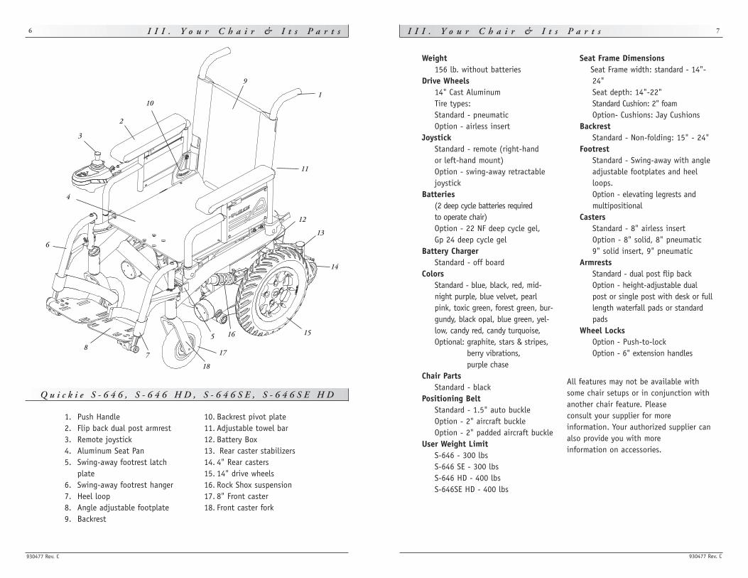
Q u i c k i e S - 6 4 6 , S - 6 4 6 H D , S - 6 4 6 S E , S - 6 4 6 S E H D
6
Weight156 lb. without batteries
Drive Wheels14" Cast AluminumTire types: Standard - pneumaticOption - airless insert
JoystickStandard - remote (right-hand or left-hand mount)Option - swing-away retractablejoystick
Batteries(2 deep cycle batteries required to operate chair)Option - 22 NF deep cycle gel, Gp 24 deep cycle gel
Battery ChargerStandard - off board
ColorsStandard - blue, black, red, mid-night purple, blue velvet, pearlpink, toxic green, forest green, bur-gundy, black opal, blue green, yel-low, candy red, candy turquoise, Optional: graphite, stars & stripes,
berry vibrations, purple chase
Chair PartsStandard - black
Positioning BeltStandard - 1.5" auto buckleOption - 2" aircraft buckleOption - 2" padded aircraft buckle
User Weight LimitS-646 - 300 lbsS-646 SE - 300 lbsS-646 HD - 400 lbsS-646SE HD - 400 lbs
Seat Frame DimensionsSeat Frame width: standard - 14"-24"Seat depth: 14"-22"Standard Cushion: 2" foamOption- Cushions: Jay Cushions
BackrestStandard - Non-folding: 15" - 24"
FootrestStandard - Swing-away with angleadjustable footplates and heelloops.Option - elevating legrests andmultipositional
CastersStandard - 8" airless insertOption - 8" solid, 8" pneumatic9" solid insert, 9" pneumatic
ArmrestsStandard - dual post flip backOption - height-adjustable dualpost or single post with desk or fulllength waterfall pads or standardpads
Wheel LocksOption - Push-to-lockOption - 6" extension handles
All features may not be available withsome chair setups or in conjunction withanother chair feature. Please consult your supplier for more information. Your authorized supplier canalso provide you with more information on accessories.
1. Push Handle2. Flip back dual post armrest3. Remote joystick4. Aluminum Seat Pan5. Swing-away footrest latch
plate6. Swing-away footrest hanger7. Heel loop8. Angle adjustable footplate9. Backrest
10. Backrest pivot plate11. Adjustable towel bar12. Battery Box13. Rear caster stabilizers14. 4" Rear casters15. 14" drive wheels16. Rock Shox suspension17. 8" Front caster18. Front caster fork
1
2
3
4
5
6
78
9
10
11
1516
13
12
14
17
18
930477 Rev. C
V . E M I ( E l e c t r o m a g n e t i c I n t e r f e r e n c e ) 9
Heed all warnings to reduce the risk of unintended brake release or chairmovement:
1. Beware of the danger from hand-held transceivers. Never turn on or use ahand-held transceiver while power to your chair is on. Use extra care if youbelieve that such a device may be in use near your chair.
2. Be aware of nearby radio or TV stations, and avoid coming close to them. 3. If unintended movement occurs, turn your chair off as soon as it is safe to
do so.
A.WHAT IS EMI?
1. EMI means: electromagnetic (EM) interference (I). EMI comes from radio wavesources such as radio transmitters and transceivers. (A “transceiver” is a devicethat both sends and receives radio wave signals).
2. There are a number of sources of intense EMI in your daily environment. Some of these are obvious and easy to avoid. Others are not, and you may notbe able to avoid them.
3. Powered wheelchairs may be susceptible to electromagnetic interference (EMI)emitted from sources such as radio stations, TV stations, amateur radio (HAM)transmitters, two-way radios, and cellular phones.
4. EMI can also be produced by conducted sources or electo-static discharge (ESD).
B. WHAT EFFECT CAN EMI HAVE?
1. EMI can cause your chair, without warning, to: • Release its brakes • Move by itself• Move in unintended directions If any of these occurs, it could result in severe injury to you or others.
2. EMI can damage the control system of your chair. This could create a safety hazard, and lead to costly repairs.
C. SOURCES OF EMI
The sources of EMI fall into three broad types: 1. Hand-Held Transceivers:
The antenna is usually mounted directly on the unit. These include: Citizens band (CB)radios, “Walkie-talkies”, Security, fire and police radios, Cellular phones, Lap-top com-puters with phone or fax, Other personal communication devices
NOTE– These devices can transmit signals while they are on, even if not in use.
I V . N o t i c e – R e a d B e f o r e U s e
930477 Rev. C
8
A. CHOOSE THE RIGHT CHAIR & SAFETY OPTIONS
Sunrise provides a choice of many power wheelchair styles, sizes and adjustments tomeet the needs of the rider. However, final selection of a wheelchair rests solely withyou and your health care professional. Choosing the best chair for you depends onsuch things as:
1. Your size, disability, strength, balance and coordination. 2. Your intended use, and your level of activity.3. The types of hazards you must overcome in daily use (in areas where you are
likely to use your chair). 4. The need for options for your safety and comfort (such as positioning belts
or special seat systems).
B. ADJUST CHAIR TO YOUR ABILITY
You need to work with your doctor, nurse or therapist, and your supplier, to fit thischair and adjust the controller settings for your level of function and ability level.
C. REVIEW THIS MANUAL OFTEN
Before using this chair you, and each person who may assist you, should read thisentire Manual and make sure to follow all instructions. Review the warnings often, untilthey are second nature to you.
D. WARNINGS
The word “WARNING” refers to a hazard or unsafe practice that may cause severe injury ordeath to you or to other persons. The “Warnings” are in four main sections, as follows:
1. V. — EMIHere you will learn about electomagnetic interference and how it can affectyour chair.
2. VI — GENERAL WARNINGS Here you will find a safety checklist and a summary of risks you need to be aware of before you ride this chair.
3. VII — WARNINGS — COMPONENTS & OPTIONSHere you will learn about your chair. Consult your supplier and your healthcare professional to help you choose the best set-up and options for yoursafety.
4. XI — BATTERIESHere you will learn about battery and charger safety, and how to avoid injury.
NOTE– Where they apply, you will also find “Warnings” in other sections of this Manual.
930477 Rev. C
V . E M I ( E l e c t r o m a g n e t i c I n t e r f e r e n c e ) 11
• 5-Zero Touch Switch• Treadle Switch• Ribbon Switch• Disc Switch• Buddy Button• Micro Light• Star Board• Penta Switch• Plate Switch• Soft Switch• Grasp Switch• Wobble Switch
Individuals with physical limitations requiring the use of a specialty controlinput device known not to be immune to 20 V/m, or not known, should exer-cise extra care around known sources of EMI.
There is no way to know the effect on EMI if you add accessories or modifythis chair. Any change to your chair may increase the risk of EMI. Parts fromother suppliers have unknown EMI properties.
F. REPORT ALL SUSPECTED EMI INCIDENTS
You should promptly report any unintended movement or brake release. Be sure toindicate whether there was a radio wave source near your chair at the time.
Contact: Sunrise Medical Customer Service Department at (800) 333-4000.
V . E M I ( E l e c t r o m a g n e t i c I n t e r f e r e n c e )
930477 Rev. C
10
2. Medium-Range Mobile Transceivers:
These include two-way radios used in police cars, fire trucks, ambulances and taxicabs. The antenna is usually mounted on the outside of the vehicle.
3. Long-Range Transceivers:
These include commercial radio and TV broadcast antenna towers and amateur (HAM) radios.
NOTE– The following are not likely to cause EMI problems: Lap-top computers (withoutphone or fax), Cordless phones, TV sets or AM/FM radios, CD or tape players.
D. DISTANCE FROM THE SOURCE
EM energy rapidly becomes more intense as you get closer to the source. For this rea-son, EMI from hand-held devices is of special concern. (See C.1) A person using oneof these devices can bring high levels of EM energy very close to your chair withoutyou knowing it.
E. IMMUNITY LEVEL
1. The level of EM energy is measured in volts per meter (V/m). Every power wheel-chair can resist EMI up to a certain level. This is called its “immunity level”.
2. The higher the immunity level, the less the risk of EMI. It is believed that a 20 V/m immunity level will protect the power wheelchair user from the morecommon sources of radio waves.
3. The configuration tested and found to be immune to at least 20 V/m is:Quickie S-646 (HD)/S-646 SE (HD) power wheelchair with a right hand mountedQTRONIX remote joystick system, 20” seat width, 18” seat depth, dual-postheight adjustable armrests, swing-away hangers and GP 24 gel cell batteries.
4. Specialty input devices with an unknown immunity level because the deviceswere not tested with the S-646 (HD)/S-646 SE (HD) and QTRONIX controllerinclude:• Breath Control• Heavy Duty Switched Joystick• Proportional Head Control• Wafer Board• Tri-Switch Head Array• Proportional Mini-Joystick/Chin Control• Proximity Head Array• Zero Touch Switch• 4-Zero Touch Switch
930477 Rev. C
V I . G e n e r a l W a r n i n g s 13
C. WEIGHT LIMIT
1. Never exceed the following weight capacities: 300 lbs - Quickie S-646 / S-646 SE; 400 lbs - Quickie S-646 HD / S-646SE HD.The weight capacity of your S-646/S-646 SE is identified by a label located onthe inside cover of the battery compartment door.
2. Never use this chair for weight training if the total weight (rider plus weightslifted) exceeds the indicated weight capacity of the wheelchair.
3. Exceeding the weight limit is likely to damage the seat, frame or fasteners andmay cause severe injury to you or others from chair failure.
4. Exceeding the weight limit will void the warranty.
D. CONTROLLER SETTINGS
Be aware that you may need to adjust the controller settings of your chair to reducethe risk of a collision, fall or tip-over.
1. Check and adjust the settings every six to twelve months (or more often, if needed).
2. Consult your supplier to adjust the control settings immediately if you noticeany change in your ability to: • Control the joystick. • Hold your torso erect. • Avoid running into objects.
E. EMI
Read Section V to learn about EMI. To reduce the risk of unintended brake release orchair movement:
1. Never turn on or use a hand-held transceiver while power to your chair is on.Use extra care if you believe that such a device may be in use near your chair.
2. Be aware of nearby radio or TV stations, and avoid coming close to them. 3. If unintended movement or brake release occurs, turn your chair off as soon
as it is safe.
F. SAFETY CHECK-LIST
Before each use of this chair: 1. Make sure the chair operates smoothly. Check for noise, vibration, or a change
in ease of use. (They may indicate low tire pressure, loose fasteners, or damageto your chair). • If you detect a problem, make sure to repair or adjust the chair. Deferring
repair or adjustment could increase the risk for injury. Your supplier can helpyou find and correct the problem.
2. Make sure batteries are charged. Green lights on charge indicator will light upwhen charge is full. Yellow lights indicate battery charge level is getting low.Red lights indicate batteries are in immediate need of charging.
V I . G e n e r a l W a r n i n g s
930477 Rev. C
12
Heed all warnings in this section. If you fail to do so a fall, tip-over or lossof control may occur and cause severe injury to your or others.
A. NOTICE TO RIDER
1. Before using this chair, you should be trained in its safe use by your healthcare professional.
2. Every wheelchair is different. Take the time to learn the feel of this chairbefore you begin riding.
3. Be aware that you must develop your own methods for the safe use of thischair that are best suited to your level of function and ability.
4. Have someone help you practice bending, reaching and transfering until youlearn how to do them safely.
5. Never try a new maneuver on your own unless you are sure it is safe. 6. Get to know the areas where you plan to use your chair. Look for hazards and
learn how to avoid them.
B. NOTICE TO ATTENDANTS
Make sure you heed all warnings and follow all instructions in each section of thismanual. (Be aware that warnings that apply to the rider also apply to you).
Notes:1. You need to work with the rider, and the rider’s doctor, nurse or therapist, to
develop safe methods best suited to your abilities and those of the rider. 2. To manually push the chair you must release the motor locks.
• Make sure you have full control over the chair when you release the motorlocks. When you do so the chair will not have brakes.
3. Propel this chair by the push handles only. They provide secure points for youto hold the rear of the chair to prevent a fall or tip-over. • Check to make sure push handle grips will not rotate or slip off.
Helping The Rider Overcome An Obstacle:1. To prevent injury to your back, use good posture and proper body mechanics.
When you lift or support the rider or tilt the chair, bend your knees slightly andkeep your back as upright and straight as you can.
2. Before each maneuver, tell the rider what you plan to do, and explain what youexpect the rider to do. This will put the rider at ease and reduce the risk of anaccident.
3. Go straight up and straight down a curb or stair. If you turn, or climb ordescend at an angle, a fall or tip-over is likely.
4. Remind the rider to lean back when you tilt the chair backward.5. Lower the chair slowly. Do not let the chair drop to the pavement or ground.
Doing so may damage the chair or injure the rider.
930477 Rev. C
V I . G e n e r a l W a r n i n g s 15
J. TERRAIN
1. This chair is designed for use on firm, even surfaces such as concrete, asphalt and indoor flooring.
2. Do not operate your chair in sand, loose soil or over rough terrain. Doing somay damage wheels, bearings, axles or motors, or loosen fasteners.
K. STREET USE
In most states, power chairs are not legal for use on public roads. Be alert tothe danger of motor vehicles on roads or in parking lots.
1. At night, or when it is hard to see, use reflective tape on your chair and clothing. 2. It may be hard for drivers to see you. Make eye contact with drivers before you
proceed. When in doubt, yield until you are sure it is safe.
L. MOTOR VEHICLE SAFETY
To date, the U.S. Department of Transportation has not approved any tie downsystem for transporting a wheelchair in a motor vehicle.
1. Never sit in this chair while in a moving vehicle. In an accident or sudden stopyou may be thrown from the chair. • Wheelchair belts are designed to position the rider only and will not
protect you in an accident; further injury may result from the belts. 2. Always move to an approved vehicle seat. You must be secured with proper
motor vehicle restraints. 3. Never transport this chair in the front seat of a vehicle. It may shift and
interfere with the driver. 4. Always secure this chair so that it cannot roll or shift.
M. CENTER OF BALANCE
The point where this chair will tip forward, back, or to the side depends onits center of balance and stability.
The Center Of Balance Is Affected By: 1. The seat height and seat angle. 2. A change in your body position, posture or weight distribution. 3. Using this chair on a ramp or slope. 4. The use of a back pack or other options, and the amount of added weight.
To Reduce The Risk Of A Fall Or Tip-Over: 1. Consult your supplier for information on modifications authorized by Sunrise
before you modify or adjust this chair.
Note– You may need to make additional changes to correct the center of balance.
2. Use extreme care until you know the balance points of this chair and how toavoid a fall or tip-over.
V I . G e n e r a l W a r n i n g s
930477 Rev. C
14
G. CHANGES & ADJUSTMENTS
Never use non-Quickie parts or make a changes to your chair unless authorizedby Sunrise. (Doing so will void the Warranty, and may create a safety hazard).
1. If you modify or adjust this chair it may increase the risk of a fall or tip-over. 2. Modifications unauthorized by Sunrise constitutes remanufacturing of the
wheelchair. This voids the warranty. The rider then assumes all future liability for the wheelchair.
H. WHEN SEATED IN A PARKED WHEELCHAIR
1. Always turn off all power to your chair when you are parked, even for amoment. This will prevent: • Accidental movement from contact with the joystick by you or others. • Unintended brake release or movement from EMI sources. (See Section V)
2. Make sure that persons who help you (for example, store clerks) are aware of the joystick and do not touch it. If they do, your chair may move suddenlywhen you do not expect it.
I. ENVIRONMENTAL CONDITIONS
Your chair is not designed for use in a heavy rain storm, or in snowy or icy conditions. 1. Contact with water or excessive moisture can cause an electrical malfunction.
The frame, motors and other chair parts are not water-tight and may rust orcorrode from the inside. To avoid a chair failure:• Minimize exposure of your chair to a rain storm or very wet conditions. • Never take your chair into a shower, tub, pool or sauna. • Do not use your chair in fresh or salt water (such as at the edge of a stream,
lake, or ocean). • Make sure battery cover is secure.• Replace joystick boot if it becomes torn or cracked.• Make sure all electrical connections are secure.• Dry the chair as soon as you can if it gets wet, or if you use water to clean it.
2. Proceed slowly and use extra care if you must operate your chair on a wet orslick surface. • Do so only if you are sure it is safe. • Stop if one or both main wheels lose traction. If this occurs, you may lose
control of your chair or fall. • Never operate your chair on a slope or ramp if there is snow, ice, water or oil
film present. • When in doubt, have someone help you.
3. When not in use, keep your chair in a clean, dry place.
Extra caution should be used when employing the disc switch or the proximi-ty head array as control devices. These two devices are susceptible to mal-function when wet.
930477 Rev. C
V I . G e n e r a l W a r n i n g s 17
O. REACHING OR LEANING
Reaching or leaning affects the center of balance of your chair. If done improp-erly, a fall or tip-over is likely. When in doubt, ask for help or use a device toextend your reach.
To Reduce the Risk of injury and/or Damage to the Chair:1. Never reach or lean if you must shift your weight sideways or rise up off the seat. 2. Never reach or lean if you must move forward in your seat to do so. Always
keep your buttocks in contact with the backrest. 3. Never reach with both hands (you may not be able to catch yourself to prevent
a fall if you lose your balance). 4. Never try to pick up an object from the floor by reaching down between your
knees. 5. Never put pressure on the footrests while reaching. This may cause the chair to
tip if you lean too far. 6. Never reach or lean over the top of the seat back. This may damage the back-
rest and cause you to fall.If You Must Reach Or Lean; Do So at Your Own Risk. Remember to:
1. Move your chair as close as you can to the object you wish to reach. 2. Rotate the front casters until they are as far forward as possible. This makes
the chair more stable.
NOTE– To do this: Move your chair past the object you want to reach, then back upalongside it. Backing up will rotate the casters forward.
3. Turn off all power to your chair. If you fail to do so, you may touch the joy-stick and cause your chair to move when you do not expect it.
4. Firmly grasp a rear wheel or an armrest with one hand. This will help to prevent a fall if the chair tips.
P. DRESSING OR CHANGING CLOTHES
Be aware that your weight will shift if you dress or change clothes whileseated in this chair. To make the chair more stable, rotate the front castersuntil they are forward.
V I . G e n e r a l W a r n i n g s
930477 Rev. C
16
N. TRANSFERS
It is dangerous to transfer on your own. It requires good balance and agility.Be aware that there is a point during every transfer when the wheelchair seatis not below you. To avoid a fall:
1. Always turn off power before you transfer to or from your chair. If you fail todo so you may touch the joystick and cause your chair to move when you donot expect it.
2. Make sure motor locks are engaged. This keeps the chair from moving when you transfer.
3. Work with your health care professional to learn safe methods. • Learn how to position your body and how to support yourself during a transfer. • Have someone help you until you are sure you can do a safe transfer on your
own. 4. Move your chair as close as you can to the seat you are transferring to.
If possible, use a transfer board. 5. Rotate the front casters until they are as far forward as possible. 6. Be careful of the footrests. If you can, remove or swing them out of the way.
• Never stand on footrests when you transfer. Doing so may damage them orcause your chair to tip.
• Make sure your feet do not “hang up” or get caught in the space betweenthe footrests.
7. Make sure armrests do not interfere. 8. Transfer as far back onto the seat surface as you can. This will reduce the risk
that you will miss the seat or fall.
930477 Rev. C
V I . G e n e r a l W a r n i n g s 19
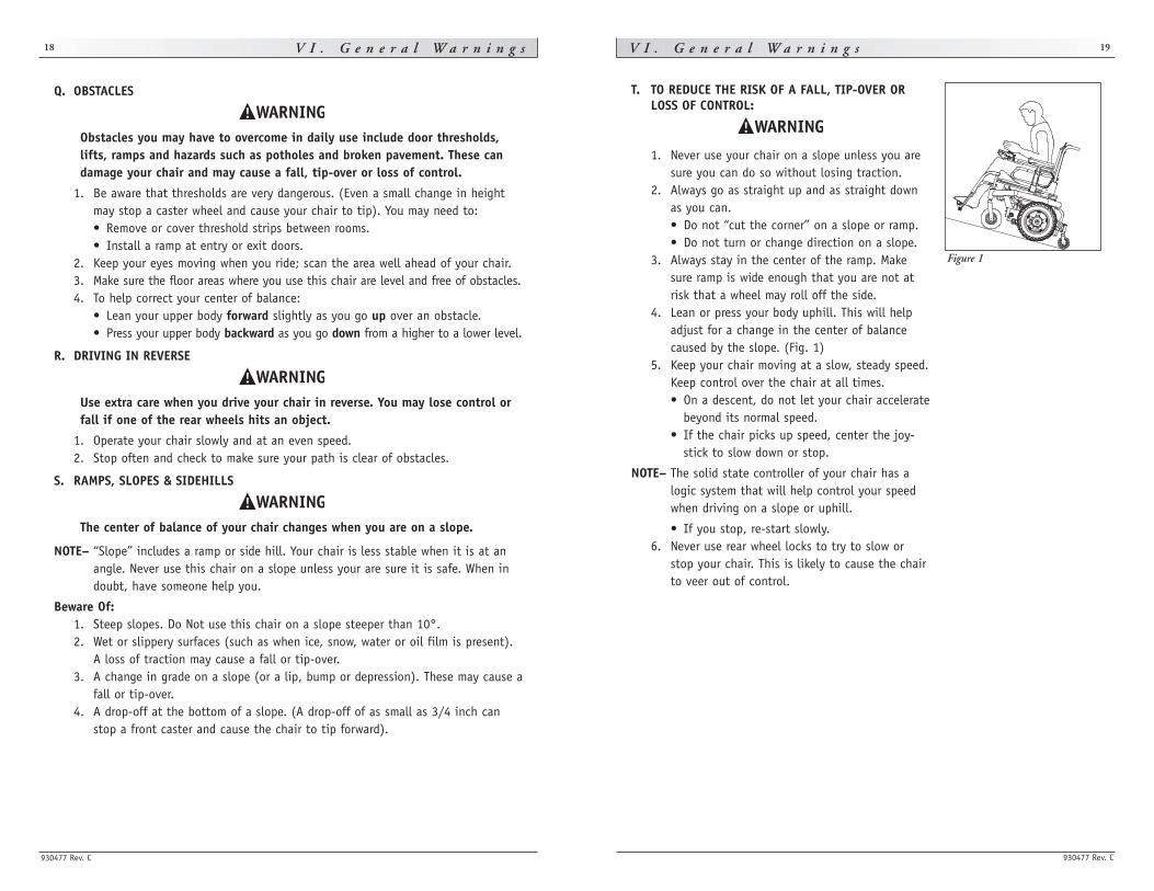
T. TO REDUCE THE RISK OF A FALL, TIP-OVER ORLOSS OF CONTROL:
1. Never use your chair on a slope unless you aresure you can do so without losing traction.
2. Always go as straight up and as straight downas you can. • Do not “cut the corner” on a slope or ramp. • Do not turn or change direction on a slope.
3. Always stay in the center of the ramp. Makesure ramp is wide enough that you are not atrisk that a wheel may roll off the side.
4. Lean or press your body uphill. This will helpadjust for a change in the center of balancecaused by the slope. (Fig. 1)
5. Keep your chair moving at a slow, steady speed.Keep control over the chair at all times. • On a descent, do not let your chair accelerate
beyond its normal speed. • If the chair picks up speed, center the joy-
stick to slow down or stop.
NOTE– The solid state controller of your chair has alogic system that will help control your speedwhen driving on a slope or uphill.
• If you stop, re-start slowly. 6. Never use rear wheel locks to try to slow or
stop your chair. This is likely to cause the chairto veer out of control.
V I . G e n e r a l W a r n i n g s
930477 Rev. C
18
Q. OBSTACLES
Obstacles you may have to overcome in daily use include door thresholds,lifts, ramps and hazards such as potholes and broken pavement. These candamage your chair and may cause a fall, tip-over or loss of control.
1. Be aware that thresholds are very dangerous. (Even a small change in heightmay stop a caster wheel and cause your chair to tip). You may need to: • Remove or cover threshold strips between rooms. • Install a ramp at entry or exit doors.
2. Keep your eyes moving when you ride; scan the area well ahead of your chair. 3. Make sure the floor areas where you use this chair are level and free of obstacles. 4. To help correct your center of balance:
• Lean your upper body forward slightly as you go up over an obstacle. • Press your upper body backward as you go down from a higher to a lower level.
R. DRIVING IN REVERSE
Use extra care when you drive your chair in reverse. You may lose control orfall if one of the rear wheels hits an object.
1. Operate your chair slowly and at an even speed. 2. Stop often and check to make sure your path is clear of obstacles.
S. RAMPS, SLOPES & SIDEHILLS
The center of balance of your chair changes when you are on a slope.
NOTE– “Slope” includes a ramp or side hill. Your chair is less stable when it is at anangle. Never use this chair on a slope unless your are sure it is safe. When indoubt, have someone help you.
Beware Of: 1. Steep slopes. Do Not use this chair on a slope steeper than 10°.2. Wet or slippery surfaces (such as when ice, snow, water or oil film is present).
A loss of traction may cause a fall or tip-over. 3. A change in grade on a slope (or a lip, bump or depression). These may cause a
fall or tip-over.4. A drop-off at the bottom of a slope. (A drop-off of as small as 3/4 inch can
stop a front caster and cause the chair to tip forward).
Figure 1
930477 Rev. C
V I . G e n e r a l W a r n i n g s 21
W. CURBS & SINGLE STEPS
1. Your chair is not designed to drive up or down a curb or step more than two(2) inches high. Doing so may: • Result in a fall or tip-over. • Damage the frame, wheels, axles or other chair parts, or loosen fasteners.
2. To prevent a fall or tip-over, use wheelchair access ramps or have someone helpyou.
3. If you must climb or descend a curb or step alone do so at your own risk anduse extreme care. • Go as straight up or straight down as you can. Never turn or climb or
descend at an angle as a fall or tip-over is likely. • Proceed slowly, at a steady speed.
4. Make sure that persons who assist you review the “Tips For Attendants” andheed all warnings.
X. STAIRS
Never use this chair to go up or down stairs, even with an attendant. Doingso is likely to cause a fall or tip-over.
Y. ESCALATORS
Never take this chair on an escalator, even with an attendant. Doing so islikely to cause a fall or tip-over.
V I . G e n e r a l W a r n i n g s
930477 Rev. C
20
U. RAMPS AT HOME & WORK
Make sure ramps meet all Building Codes for your area.
For your safety, have a licensed contractor build or remodel ramp to meet all standards.
NOTE– The proper design will vary, depending on such things as: the length andheight of the ramp; the need for an intermediate platform; landing size; doors,and the direction of swing, and; whether the ramp includes a turn or angle.
At A Minimum: 1. Open sides of ramp must have side rails to prevent your chair from going over
the edge. 2. Slope must not be steeper than one inch in height for every one foot of slope
length. 3. Ramp surface must be even, and have a non-skid surface. 4. You may need to add a section at the top or bottom to avoid a lip or drop-off. 5. Ramp must be sturdy. Add bracing if needed, so ramp does not “bow” when you
ride on it.
V. WHEELCHAIR LIFTS
Wheelchair lifts are used in vans, buses, and buildings to help you move fromone level to another.
1. Always turn off all power to your chair when you are on a lift. If you fail to doso, you may touch the joystick by accident and cause your chair to drive offthe platform. (Be aware that a “roll-stop” at the end of the platform may notprevent this).
2. Make sure there is not a lip or drop-off at the top or bottom of the platform.These may cause a fall or tip-over. When in doubt, have someone help you.
3. Always position the rider securely in the chair to help prevent falls while on a lift.4. Avoid moving forward if a wheel is “hung up” on the lip of the ramp. Backup,
reposition the caster for a more direct approach. And slowly try again.
930477 Rev. C
V I I . W a r n i n g s : C o m p o n e n t s & O p t i o n s 23
F. FOOTRESTS
1. At the lowest point, footrests should be at least 2 1/2 inches off the ground.If set too LOW, they may “hang up” on obstacles you can expect to find in nor-mal use. This may cause the chair to stop suddenly and tip forward.
2. To avoid a trip or fall when you transfer: • Make sure your feet do not “hang up” or get caught in the space between
the footrests.• Avoid putting weight on the footrests, as the chair may tip forward. • Remove or swing the footrests out of the way, if possible.
3. Never lift this chair by the footrests. Footrests detach and will not bear the weight of this chair. Lift this chair only by non-detachable parts of the main frame.
G. MOTOR LOCKS
1. Do not engage or disengage motor locks unless power to the chair is off. 2. Be aware that the chair will not have brakes when motor locks are in the
free-wheel position. 3. Make sure that the person pushing the chair has full control when motor locks
are disengaged.
H. ON/OFF SWITCH
1. Never use the ON/OFF switch to stop the chair except in an emergency. This will result in an abrupt stop, and may cause you to fall.
2. To slow your chair to a stop, return the joystick to neutral.
I. PNEUMATIC TIRES
Proper inflation extends the life of your tires and makes your chair easier to use.
1. Do not use this chair if any of the tires are under- or over-inflated. Check weekly for proper inflation level, as listed on the tire sidewall.
2. Low pressure in a tire may cause the chair to veer to one side and result in a loss of control.
3. An over-inflated tire may burst. 4. Never use a gas station air pump to inflate a tire. Such pumps provide air at
high volume, and could cause the tire to burst. To prevent tire damage: • Use a hand pump (or a low volume air pump) to inflate tires. • Use a tire gauge to check pressure.
5. Driving over sharp objects may cause damage to pneumatic tires and tubes.
V I I . W a r n i n g s : C o m p o n e n t s & O p t i o n s
930477 Rev. C
22
Note: If you use parts or make changes not authorized by Sunrise it may cre-ate a safety hazard and will void the Warranty.
A. ANTI-TIP LEVERS
Never remove or alter anti-tip levers. They help keep your chair from tippingover backward in normal use. Make sure rubber rollers are in good condition.
B. ARMRESTS
Armrests detach and will not bear the weight of this chair.
1. Never lift this chair by its armrests. They may come loose or break. 2. Lift this chair only by non-detachable parts of the main frame.
C. BATTERIES
1. Only deep cycled sealed case construction batteries should be used in thisdevice.
2. To prevent an acid spill, always keep batteries upright (wet cell batteries only). 3. Never smoke or hold an open flame near batteries. They are a known
explosion hazard.4. Always wear rubber gloves and safety glasses when you handle batteries.5. Read all of section XI Batteries before attempting to change or charge batteries.
D. CUSHIONS & SLING SEATS
1. Quickie sling seats, standard foam cushions, and other body supports, are notdesigned for the relief of pressure.
2. If you suffer from pressure sores, or if you are at risk that they will occur, youmay need a special seat system or a device to control your posture. • Consult your doctor, nurse or therapist to find out if you need such a device
for your well-being.
E. FASTENERS
Many of the screws, bolts and nuts on this chair are special high-strengthfasteners. Use of improper fasteners may cause your chair to fail.
1. Only use fasteners provided by Sunrise.2. If fasteners become loose, tighten them as soon as you can. 3. Over- or under-tightened fasteners may fail or cause damage to chair parts.
• See Section IX, Set-Up. Adjustment, & Use, for proper torque settings.
930477 Rev. C
V I I . W a r n i n g s : C o m p o n e n t s & O p t i o n s 25
M. SEATING SYSTEMS
1. Use of a seating system not approved by Sunrise may alter the center of balance of this chair. This may cause a fall or tip-over.
2. Never change the seating system of your chair unless you consult your supplier first.
N. UPHOLSTERY FABRIC
1. Replace worn or torn fabric of seat sling and seat back as soon as you can. If you fail to do so, the seat may fail and cause you to fall. Worn fabrics mayincrease the potential for a fire hazard.
2. Sling fabric will deteriorate with age and use. Look for fraying, thin spots, orstretching of fabric at rivet holes. Replace fabric as required.
3. “Dropping down” into sling seat will weaken fabric and result in the need toinspect and replace sling on a more frequent basis.
4. Be aware that washing may reduce flame retardation of the fabric.
V I I . W a r n i n g s : C o m p o n e n t s & O p t i o n s
930477 Rev. C
24
J. POSITIONING BELTS (STANDARD OR OPTIONAL)
Use a positioning belt only to help support your posture. Improper use ofsuch belts may cause severe injury or death.
1. Make sure you are not at risk to slide down in the wheelchair seat. If this occurs,you may suffer chest compression or suffocate due to pressure from the belt.
2. A pelvic wedge or a similar device can help keep you from sliding down in theseat. Consult your health care professional to find out if you need such a device.
3. The belt must be snug, but must not be so tight that it interferes with breath-ing. You should be able to slide your open hand, flat, between the belt andyour stomach.
4. Make sure you can easily remove the belt in an emergency. 5. Never use a positioning belt:
• In place of a motor vehicle seat belt. In an accident or sudden stop you maybe thrown from the chair. A positioning belt will not prevent this, and fur-ther injury may result from the belt.
• As a restraint. A restraint requires a doctor’s order. • On a rider who is comatose or agitated.
K. PUSH HANDLES
1. Push handles provide secure points for an attendant to propel and control thechair. This helps to prevent a fall or tip-over.
2. Check to make sure push handle grips will not rotate or slip off.
L. REAR WHEEL LOCKS (OPTIONAL)
If you request them, we will install rear wheel locks at Sunrise.
1. Rear wheel locks are not designed to slow or stop a moving wheelchair. Never apply them when your chair is moving. Doing so may cause you to veerout of control. • Use wheel locks only to keep the rear wheels from rolling when your chair isat a complete stop.
2. Low pressure in a rear tire may cause the wheel lock on that side to slip andmay allow the wheel to turn when you do not expect it.
3. Make sure lock arms embed in tires at least 3/8 inch when locked. If you fail todo so, the locks may not work.
930477 Rev. C
I X . S e t - u p , A d j u s t m e n t & U s e 27
A. NOTES
1. Work Surface For Set-Up:
Use a flat surface, such as a table, to assemble, adjust and check your chair. This makes the steps easier and helps ensure a correct set-up.
2. Fasteners: • Many of the screws and bolts on this chair are special high-strength fasteners
and may have special coatings.• Many nuts are of the Nylock type. They have a plastic insert to help prevent
loosening. • Only use screws, bolts and nuts provided by Sunrise.
1. Use of improper fasteners may cause the chair to fail.2. Over- or under-tightened fasteners may fail or cause damage to chair parts.3. If bolts or screws become loose,tighten them as soon as you can. Loose
bolts or screws can cause damage to other chair parts causing them to fail.3. Washers & Spacers:
• Note the position of washers and spacers before disassembly. • To avoid damage to the frame, replace all washers and spacers when you
reassemble parts. 4. Torque Settings:
A torque setting is the optimal tightening for a particular fastener. Use a torquewrench that measures inch-pounds to secure screws, nuts and bolts on this chair.
NOTE– Unless otherwise noted, use a torque setting of 120 inch-pounds for all fasteners.
B. TOOLS YOU WILL NEED
1. Basic Tool Kit: To set-up, adjust and maintain your chair you will need the following tools:
• 7/16" socket wrench• 1/2" box and open-end wrench• 3/4" box and socket wrench• 5/32" Allen wrench• 3/16" Allen wrench• Phillips screwdriver #2• Custom axle wrench (or a 1/2" open-end wrench)
You can obtain a multi-purpose tool kit from Sunrise, or buy the tools you need from ahardware store.
2. Torque Wrench: If you plan to adjust and maintain this chair yourself, Sunrise recommends that youuse a torque wrench.
NOTE– The wrench must measure inch-pounds. You can buy a torque wrench and prop-er sockets from a hardware store.
V I I I . T i p s f o r A t t e n d a n t s
930477 Rev. C
26
1. Persons who help a rider do one of the following tasks should review andheed the warnings “Notice to Attendants” and all warnings in this Manualfor that task.
2. The “Tips” that follow are suggestions only. Be aware that you will need tolearn safe methods best suited to the rider and to your abilities. Consultyour health care professional for instructions.
A. TO CLIMB A CURB OR SINGLE STEP
The following is one way to safely help a rider climb a curb or single stepgoing forward:
1. Stay behind the chair. 2. Face the curb and tilt the chair up on the rear wheels so that the front casters
clear the curb or step. 3. Move forward, placing the front casters on the upper level as soon as you are
sure they are past the edge. 4. Continue forward until the rear wheels contact the face of the curb or step.
Lift and roll the rear wheels to the upper level.
B. TO DESCEND A CURB OR SINGLE STEP
The following is one way to safely help a rider descend a curb or single stepgoing backward:
1. Stay at the rear of the chair. 2. Several feet before your reach the edge of the curb or step, turn the chair
around and pull it backward. 3. Proceed carefully. Look over your shoulder and carefully step back until you are
off the curb or stair and standing on the lower level. 4. Pull the chair toward you until the rear wheels reach the edge of the curb or
step. Then allow the rear wheels to slowly roll down onto the lower level. 5. When the rear wheels are safely on the lower level, tilt the chair back to its
balance point. This will lift the front casters off the curb or step. 6. Keep the chair in balance and take small steps backward. Be sure to look where
you are going. Turn the chair around and gently lower front casters to the ground.
I X . S e t - u p , A d j u s t m e n t & U s e
930477 Rev. C
28
930477 Rev. C
I X . S e t - u p , A d j u s t m e n t & U s e 29
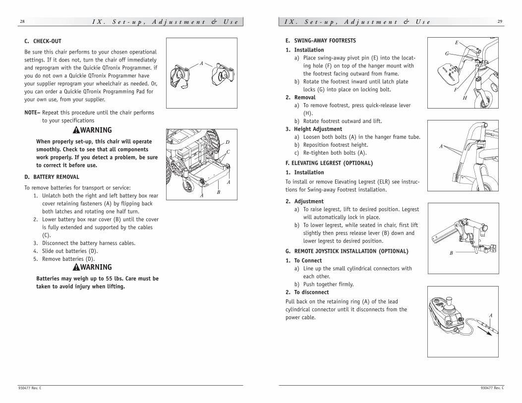
E. SWING-AWAY FOOTRESTS
1. Installationa) Place swing-away pivot pin (E) into the locat-
ing hole (F) on top of the hanger mount withthe footrest facing outward from frame.
b) Rotate the footrest inward until latch platelocks (G) into place on locking bolt.
2. Removala) To remove footrest, press quick-release lever
(H).b) Rotate footrest outward and lift.
3. Height Adjustmenta) Loosen both bolts (A) in the hanger frame tube.b) Reposition footrest height.c) Re-tighten both bolts (A).
F. ELEVATING LEGREST (OPTIONAL)
1. Installation
To install or remove Elevating Legrest (ELR) see instruc-tions for Swing-away Footrest installation.
2. Adjustmenta) To raise legrest, lift to desired position. Legrest
will automatically lock in place.b) To lower legrest, while seated in chair, first lift
slightly then press release lever (B) down andlower legrest to desired position.
G. REMOTE JOYSTICK INSTALLATION (OPTIONAL)
1. To Connecta) Line up the small cylindrical connectors with
each other.b) Push together firmly.
2. To disconnect
Pull back on the retaining ring (A) of the lead cylindrical connector until it disconnects from thepower cable.
C. CHECK-OUT
Be sure this chair performs to your chosen operationalsettings. If it does not, turn the chair off immediatelyand reprogram with the Quickie QTronix Programmer. ifyou do not own a Quickie QTronix Programmer haveyour supplier reprogram your wheelchair as needed. Or,you can order a Quickie QTronix Programming Pad foryour own use, from your supplier.
NOTE– Repeat this procedure until the chair performsto your specifications
When properly set-up, this chair will operatesmoothly. Check to see that all componentswork properly. If you detect a problem, be sureto correct it before use.
D. BATTERY REMOVAL
To remove batteries for transport or service:1. Unlatch both the right and left battery box rear
cover retaining fasteners (A) by flipping backboth latches and rotating one half turn.
2. Lower battery box rear cover (B) until the coveris fully extended and supported by the cables(C).
3. Disconnect the battery harness cables.4. Slide out batteries (D).5. Remove batteries (D).
Batteries may weigh up to 55 lbs. Care must betaken to avoid injury when lifting.
E
H
F
G
A
A
C
D
B
A
A
A
B
930477 Rev. C
I X . S e t - u p , A d j u s t m e n t & U s e 31
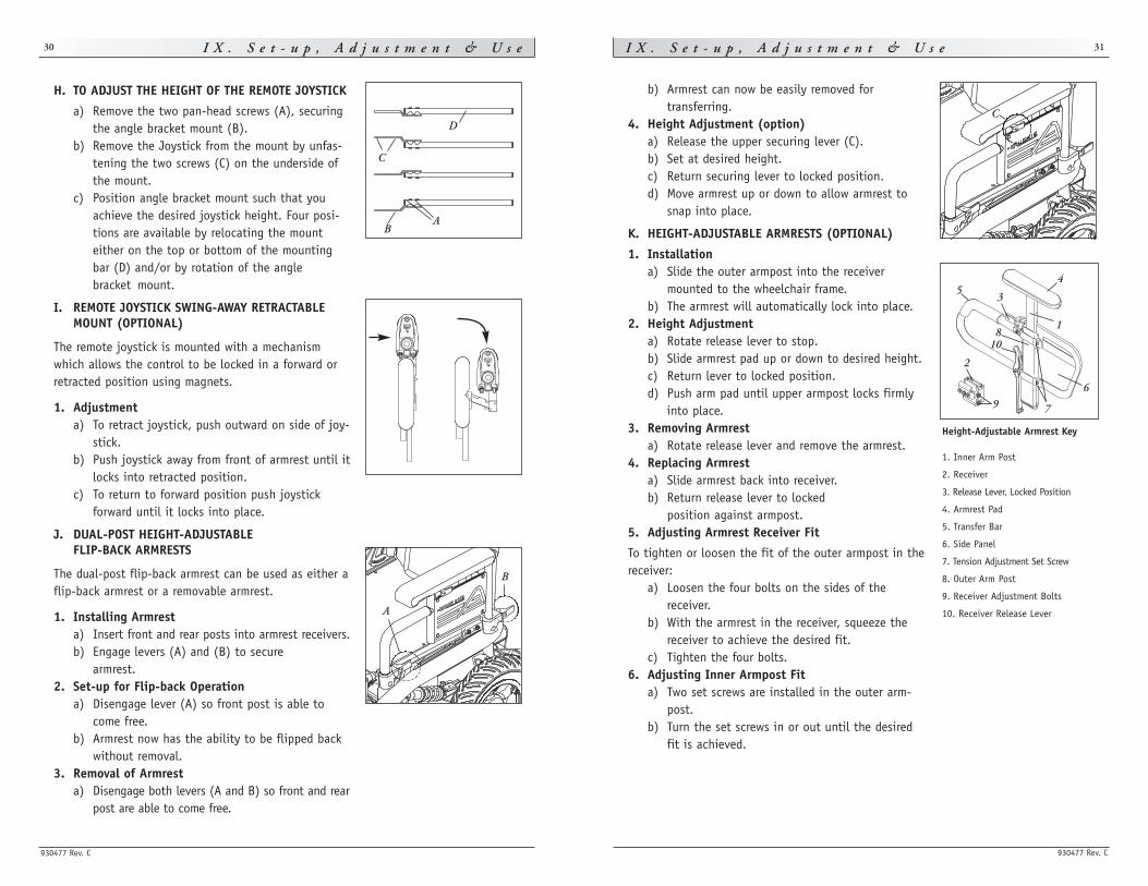
b) Armrest can now be easily removed for transferring.
4. Height Adjustment (option)a) Release the upper securing lever (C).b) Set at desired height.c) Return securing lever to locked position.d) Move armrest up or down to allow armrest to
snap into place.
K. HEIGHT-ADJUSTABLE ARMRESTS (OPTIONAL)
1. Installationa) Slide the outer armpost into the receiver
mounted to the wheelchair frame.b) The armrest will automatically lock into place.
2. Height Adjustmenta) Rotate release lever to stop.b) Slide armrest pad up or down to desired height.c) Return lever to locked position.d) Push arm pad until upper armpost locks firmly
into place.3. Removing Armrest
a) Rotate release lever and remove the armrest.4. Replacing Armrest
a) Slide armrest back into receiver.b) Return release lever to locked
position against armpost.5. Adjusting Armrest Receiver Fit
To tighten or loosen the fit of the outer armpost in thereceiver:
a) Loosen the four bolts on the sides of thereceiver.
b) With the armrest in the receiver, squeeze thereceiver to achieve the desired fit.
c) Tighten the four bolts.6. Adjusting Inner Armpost Fit
a) Two set screws are installed in the outer arm-post.
b) Turn the set screws in or out until the desiredfit is achieved.
I X . S e t - u p , A d j u s t m e n t & U s e
930477 Rev. C
30
H. TO ADJUST THE HEIGHT OF THE REMOTE JOYSTICK
a) Remove the two pan-head screws (A), securingthe angle bracket mount (B).
b) Remove the Joystick from the mount by unfas-tening the two screws (C) on the underside ofthe mount.
c) Position angle bracket mount such that youachieve the desired joystick height. Four posi-tions are available by relocating the mounteither on the top or bottom of the mountingbar (D) and/or by rotation of the anglebracket mount.
I. REMOTE JOYSTICK SWING-AWAY RETRACTABLEMOUNT (OPTIONAL)
The remote joystick is mounted with a mechanismwhich allows the control to be locked in a forward orretracted position using magnets.
1. Adjustmenta) To retract joystick, push outward on side of joy-
stick.b) Push joystick away from front of armrest until it
locks into retracted position.c) To return to forward position push joystick
forward until it locks into place.
J. DUAL-POST HEIGHT-ADJUSTABLE FLIP-BACK ARMRESTS
The dual-post flip-back armrest can be used as either aflip-back armrest or a removable armrest.
1. Installing Armresta) Insert front and rear posts into armrest receivers.b) Engage levers (A) and (B) to secure
armrest.2. Set-up for Flip-back Operation
a) Disengage lever (A) so front post is able tocome free.
b) Armrest now has the ability to be flipped backwithout removal.
3. Removal of Armresta) Disengage both levers (A and B) so front and rear
post are able to come free.
A
B
A
C
B
DC
Height-Adjustable Armrest Key
1. Inner Arm Post
2. Receiver
3. Release Lever, Locked Position
4. Armrest Pad
5. Transfer Bar
6. Side Panel
7. Tension Adjustment Set Screw
8. Outer Arm Post
9. Receiver Adjustment Bolts
10. Receiver Release Lever
1
2
3
45
6
7
8
9
10
930477 Rev. C
I X . S e t - u p , A d j u s t m e n t & U s e 33
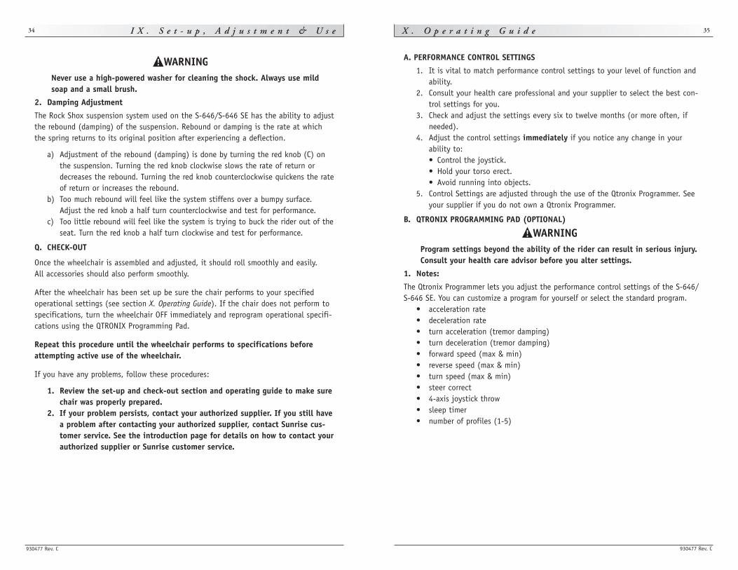
O. WHEEL LOCKS
Wheel locks are installed by Sunrise when requested onthe Quickie S-646/S-646 SE.
1. MountingThe wheel lock mounts to the motor mount. Use a torque setting of 100 in./lbs when adjustingwheel locks.
a) Loosen bolts (D).b) Slide mounting bracket toward rear wheel until
clamp embeds into tire to prevent wheel move-ment when in locked position.
c) Tighten screws.
NOTE– Wheel lock adjustment will be done through thedrive-wheel spokes.
P. SUSPENSION
Note– Equivalent adjustments should be done to boththe right and left suspension element.
It is important to properly adjust the pre-load and damp-ing to ensure proper comfort and control for the rider.
1. Pre-Load Adjustment
With the rider seated in the chair and with batteriesinstalled, insure that the main horizontal member of thebase frame is parallel to the ground. If it is not parallel,adjust spring collar (B) in either direction to adjust. Ifthe rear of the base frame is lower than the front, adjustthe spring collar clockwise when viewed from the rear ofthe chair. If the rear of the base frame is higher thanthe front, adjust the spring collar counter-clockwisewhen viewed from the rear of the chair.
The spring pre-load ring should never beadjusted so that the shock spring is less thanfour inches long with the chair unoccupied andthe batteries installed. Too much spring pre-load may cause the spring to fail.
I X . S e t - u p , A d j u s t m e n t & U s e
930477 Rev. C
32
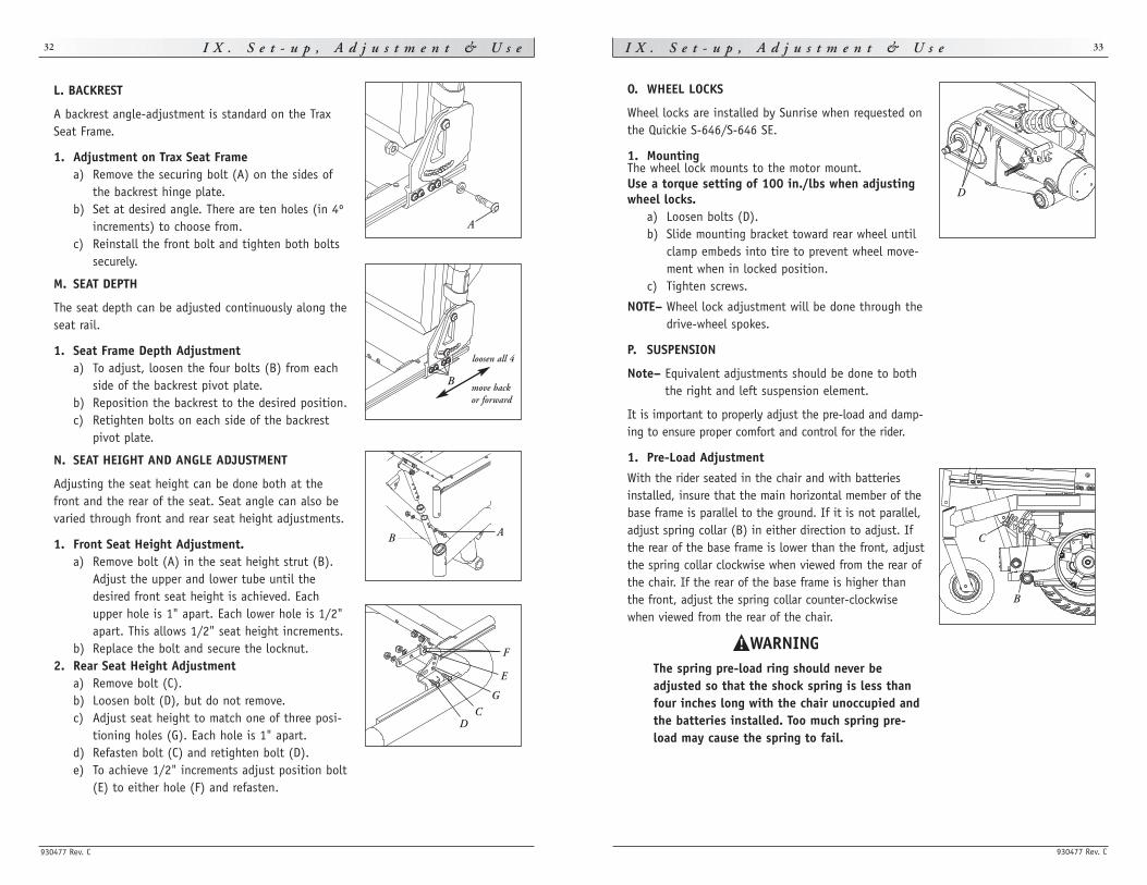
L. BACKREST
A backrest angle-adjustment is standard on the TraxSeat Frame.
1. Adjustment on Trax Seat Framea) Remove the securing bolt (A) on the sides of
the backrest hinge plate.b) Set at desired angle. There are ten holes (in 4º
increments) to choose from.c) Reinstall the front bolt and tighten both bolts
securely.
M. SEAT DEPTH
The seat depth can be adjusted continuously along theseat rail.
1. Seat Frame Depth Adjustmenta) To adjust, loosen the four bolts (B) from each
side of the backrest pivot plate.b) Reposition the backrest to the desired position.c) Retighten bolts on each side of the backrest
pivot plate.
N. SEAT HEIGHT AND ANGLE ADJUSTMENT
Adjusting the seat height can be done both at thefront and the rear of the seat. Seat angle can also bevaried through front and rear seat height adjustments.
1. Front Seat Height Adjustment.a) Remove bolt (A) in the seat height strut (B).
Adjust the upper and lower tube until thedesired front seat height is achieved. Eachupper hole is 1" apart. Each lower hole is 1/2"apart. This allows 1/2" seat height increments.
b) Replace the bolt and secure the locknut.2. Rear Seat Height Adjustment
a) Remove bolt (C).b) Loosen bolt (D), but do not remove.c) Adjust seat height to match one of three posi-
tioning holes (G). Each hole is 1" apart.d) Refasten bolt (C) and retighten bolt (D).e) To achieve 1/2" increments adjust position bolt
(E) to either hole (F) and refasten.
A
Bmove backor forward
loosen all 4
D
AB
E
F
DC
G
C
B
930477 Rev. C
X . O p e r a t i n g G u i d e 35
A. PERFORMANCE CONTROL SETTINGS
1. It is vital to match performance control settings to your level of function andability.
2. Consult your health care professional and your supplier to select the best con-trol settings for you.
3. Check and adjust the settings every six to twelve months (or more often, ifneeded).
4. Adjust the control settings immediately if you notice any change in your ability to: • Control the joystick. • Hold your torso erect. • Avoid running into objects.
5. Control Settings are adjusted through the use of the Qtronix Programmer. Seeyour supplier if you do not own a Qtronix Programmer.
B. QTRONIX PROGRAMMING PAD (OPTIONAL)
Program settings beyond the ability of the rider can result in serious injury.Consult your health care advisor before you alter settings.
1. Notes:
The Qtronix Programmer lets you adjust the performance control settings of the S-646/S-646 SE. You can customize a program for yourself or select the standard program.
• acceleration rate• deceleration rate• turn acceleration (tremor damping)• turn deceleration (tremor damping)• forward speed (max & min)• reverse speed (max & min)• turn speed (max & min)• steer correct• 4-axis joystick throw• sleep timer• number of profiles (1-5)
I X . S e t - u p , A d j u s t m e n t & U s e
930477 Rev. C
34
Never use a high-powered washer for cleaning the shock. Always use mildsoap and a small brush.
2. Damping Adjustment
The Rock Shox suspension system used on the S-646/S-646 SE has the ability to adjustthe rebound (damping) of the suspension. Rebound or damping is the rate at whichthe spring returns to its original position after experiencing a deflection.
a) Adjustment of the rebound (damping) is done by turning the red knob (C) onthe suspension. Turning the red knob clockwise slows the rate of return ordecreases the rebound. Turning the red knob counterclockwise quickens the rateof return or increases the rebound.
b) Too much rebound will feel like the system stiffens over a bumpy surface.Adjust the red knob a half turn counterclockwise and test for performance.
c) Too little rebound will feel like the system is trying to buck the rider out of theseat. Turn the red knob a half turn clockwise and test for performance.
Q. CHECK-OUT
Once the wheelchair is assembled and adjusted, it should roll smoothly and easily. All accessories should also perform smoothly.
After the wheelchair has been set up be sure the chair performs to your specified operational settings (see section X. Operating Guide). If the chair does not perform tospecifications, turn the wheelchair OFF immediately and reprogram operational specifi-cations using the QTRONIX Programming Pad.
Repeat this procedure until the wheelchair performs to specifications beforeattempting active use of the wheelchair.
If you have any problems, follow these procedures:
1. Review the set-up and check-out section and operating guide to make surechair was properly prepared.
2. If your problem persists, contact your authorized supplier. If you still havea problem after contacting your authorized supplier, contact Sunrise cus-tomer service. See the introduction page for details on how to contact yourauthorized supplier or Sunrise customer service.
930477 Rev. C
X . O p e r a t i n g G u i d e 37
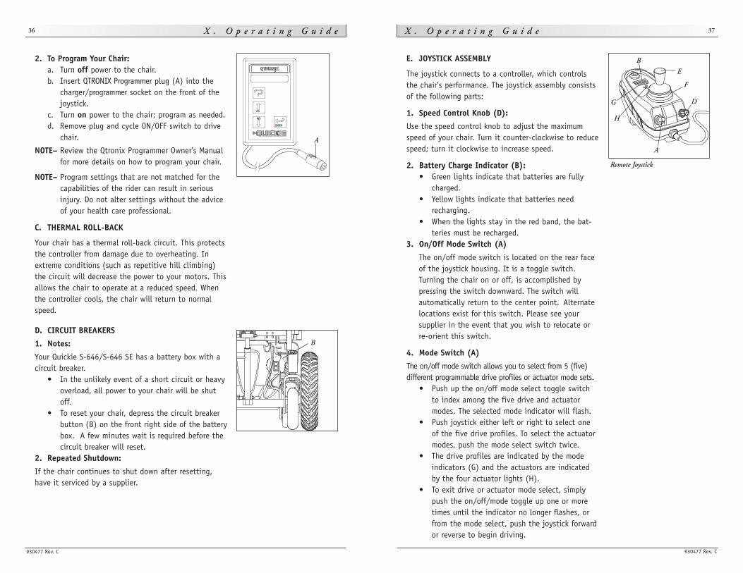
E. JOYSTICK ASSEMBLY
The joystick connects to a controller, which controlsthe chair’s performance. The joystick assembly consistsof the following parts:
1. Speed Control Knob (D):
Use the speed control knob to adjust the maximumspeed of your chair. Turn it counter-clockwise to reducespeed; turn it clockwise to increase speed.
2. Battery Charge Indicator (B):• Green lights indicate that batteries are fully
charged. • Yellow lights indicate that batteries need
recharging. • When the lights stay in the red band, the bat-
teries must be recharged.3. On/Off Mode Switch (A)
The on/off mode switch is located on the rear faceof the joystick housing. It is a toggle switch.Turning the chair on or off, is accomplished bypressing the switch downward. The switch willautomatically return to the center point. Alternatelocations exist for this switch. Please see yoursupplier in the event that you wish to relocate orre-orient this switch.
4. Mode Switch (A)
The on/off mode switch allows you to select from 5 (five)different programmable drive profiles or actuator mode sets.
• Push up the on/off mode select toggle switchto index among the five drive and actuatormodes. The selected mode indicator will flash.
• Push joystick either left or right to select oneof the five drive profiles. To select the actuatormodes, push the mode select switch twice.
• The drive profiles are indicated by the modeindicators (G) and the actuators are indicatedby the four actuator lights (H).
• To exit drive or actuator mode select, simplypush the on/off/mode toggle up one or moretimes until the indicator no longer flashes, orfrom the mode select, push the joystick forwardor reverse to begin driving.
X . O p e r a t i n g G u i d e
930477 Rev. C
36
2. To Program Your Chair: a. Turn off power to the chair. b. Insert QTRONIX Programmer plug (A) into the
charger/programmer socket on the front of thejoystick.
c. Turn on power to the chair; program as needed. d. Remove plug and cycle ON/OFF switch to drive
chair.
NOTE– Review the Qtronix Programmer Owner’s Manualfor more details on how to program your chair.
NOTE– Program settings that are not matched for thecapabilities of the rider can result in seriousinjury. Do not alter settings without the adviceof your health care professional.
C. THERMAL ROLL-BACK
Your chair has a thermal roll-back circuit. This protectsthe controller from damage due to overheating. Inextreme conditions (such as repetitive hill climbing)the circuit will decrease the power to your motors. Thisallows the chair to operate at a reduced speed. Whenthe controller cools, the chair will return to normalspeed.
D. CIRCUIT BREAKERS
1. Notes:
Your Quickie S-646/S-646 SE has a battery box with acircuit breaker.
• In the unlikely event of a short circuit or heavyoverload, all power to your chair will be shutoff.
• To reset your chair, depress the circuit breakerbutton (B) on the front right side of the batterybox. A few minutes wait is required before thecircuit breaker will reset.
2. Repeated Shutdown:
If the chair continues to shut down after resetting,have it serviced by a supplier.
B
AA
D
E
F
G
H
B
Remote Joystick
930477 Rev. C
X . O p e r a t i n g G u i d e 39X . O p e r a t i n g G u i d e
930477 Rev. C
38
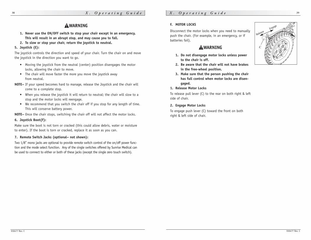
F. MOTOR LOCKS
Disconnect the motor locks when you need to manuallypush the chair. (For example, in an emergency, or ifbatteries fail).
1. Do not disengage motor locks unless powerto the chair is off.
2. Be aware that the chair will not have brakesin the free-wheel position.
3. Make sure that the person pushing the chairhas full control when motor locks are disen-gaged.
1. Release Motor Locks
To release pull lever (C) to the rear on both right & leftside of chair.
2. Engage Motor Locks
To engage push lever (C) toward the front on bothright & left side of chair.
C
Engage
Release1. Never use the ON/OFF switch to stop your chair except in an emergency.
This will result in an abrupt stop, and may cause you to fall.2. To slow or stop your chair, return the joystick to neutral.
5. Joystick (E):
The joystick controls the direction and speed of your chair. Turn the chair on and movethe joystick in the direction you want to go.
• Moving the joystick from the neutral (center) position disengages the motorlocks, allowing the chair to move.
• The chair will move faster the more you move the joystick away from neutral.
NOTE– If your speed becomes hard to manage, release the Joystick and the chair willcome to a complete stop.
• When you release the joystick it will return to neutral; the chair will slow to astop and the motor locks will reengage.
• We recommend that you switch the chair off if you stop for any length of time.This will conserve battery power.
NOTE– Once the chair stops, switching the chair off will not affect the motor locks.
6. Joystick Boot(F):
Make sure the boot is not torn or cracked (this could allow debris, water or moistureto enter). If the boot is torn or cracked, replace it as soon as you can.
7. Remote Switch Jacks (optional– not shown):
Two 1/8” mono jacks are optional to provide remote switch control of the on/off power func-tion and the mode select function. Any of the single switches offered by Sunrise Medical canbe used to connect to either or both of these jacks (except the single zero touch switch).
930477 Rev. C
X I . B a t t e r i e s 41X I . B a t t e r i e s
930477 Rev. C
40
• Never expose charger to rain or snow. • Never unplug charger by pulling on the electrical cord. This will damage the
cord. • Never open a charger or attempt to repair it yourself. Return charger to Sunrise
or have repairs made only by a qualified person. • Keep cord out of the way, where it will not be stepped on, tripped over, or
damaged.3. Caution — To Avoid Damage to the Battery:
• Make sure you use the correct setting for sealed (gel) batteries (located on theoff-board charger).
• Never charge a frozen battery. A fully charged battery will rarely freeze, but thefluid in a discharged battery can freeze at 16 degrees Fahrenheit (minus 9degrees Centigrade). If you suspect a battery is frozen, thaw it before charging.
Lead acid batteries generate explosive gas while charging. Completely readand follow all warnings about the batteries in this user instruction manualand any labels applied to the product. Failure to do so could result in fire,explosion, injury and/or death.
C. ACID BURNS (UNSEALED WET CELL BATTERIES)
Acid in batteries is corrosive. It can cause serious burns to the eyes and skin and candamage floors, furniture, clothing and your wheelchair.
1. Use extreme care not to spill acid when you handle batteries. Keep batteries upright.
2. Avoid contact of acid with bare skin or clothing.3. Always wear rubber gloves and safety glasses when you handle batteries.4. If acid contacts your skin or clothing, wash immediately with soap and
water.5. If acid contacts your eyes, immediately flood eyes with cold running water
for at least 15 minutes. Seek medical attention immediately.
D. CONNECTING BATTERIES IN BATTERY BOX
1. Each battery weighs up to 55 lbs. Take care to avoid injury when lifting.2. Keep batteries upright. Take care not to spill acid (wet cell batteries). 3. Always wear rubber gloves and safety glasses when you handle batteries.4. Before working around batteries, remove all metal personal effects, such as
necklaces, rings, watches, pins, and other metal jewelry that might contactbattery terminal and cause a short.
A. INTRODUCTION
1. Notes:• Batteries supply the power for your chair. They contain a finite amount of ener-
gy and have limits on how long they can store and supply energy. • You can charge batteries only a certain number of times before they will fail
and no longer hold a charge. • For answers to questions about batteries, consult your supplier.
2. Use Proper Batteries:
Your chair operates on two 12 volt batteries. • They should be 22 NF or Gp 24 size with a minimum of 40 ampere hour rating.
Only deep cycle sealed case construction batteries should be used in this device.• When you buy a replacement, insist on a deep cycle sealed case type. Do not
use a car starter battery. 3. Breaking In:
• A battery requires “breaking-in” for the first 6 to 12 charges. It will not accepta full charge for this period.
• It is best to limit the length of your trips until you break the batteries in andyou know the range of your chair.
4. Discharged Batteries:• Never allow a battery to completely discharge. If you operate your wheelchair until
it has almost stopped, you will greatly reduce the life of your batteries. • Never let a battery sit in a discharged condition. Give unused or stored batter-
ies a full charge once per month. • Always fully charge the batteries. Avoid “topping Off” with frequent
charges.
Never connect a life support or auxiliary device to a wheelchair battery. Theelectrical system may fail, and result in severe injury to or death of rider.
B. BATTERY CHARGER
A battery charger produces a direct current (DC). When applied to a discharged battery, this reverses the chemical reaction that led to its discharge.
1. Charge Rate. How fast a battery will charge depends on: • Its electrical capacity; state of charge; electrolyte temperature, and; internal
condition. • The DC output of the charger. (The charge rate will vary if the alternating
current (AC) supply is higher or lower than 110 volts). 2. Caution — To Avoid Damage to the Charger:
• Never place the charger on top of a battery during charging. (Gases from thebattery can damage the charger and may lead to an explosion or fire).
• Never place a battery on top of the charger.
930477 Rev. C
X I . B a t t e r i e s 43X I . B a t t e r i e s
930477 Rev. C
42
3. Never use an extension cord. Use of an improp-er cord could damage the charger, or cause afire or electrical shock.
4. A battery emits explosive hydrogen gas duringcharging. To reduce the risk of fire or explosion:• Make sure area is well vented. Never charge
battery in a closed-in area.• Never smoke or allow a spark, flame or high
heat near battery during charging.• Never allow metal tools or chair parts to
make direct contact across both terminals.5. Never look directly into cells when charging
battery.Always:
1. Use the charger that comes with your wheel-chair. Read and follow all instructions andwarnings.
2. Make sure room is well ventilated. 3. Turn off all power to your chair. 4. Connect and disconnect battery cables with
caution. Only connect the charger to the powersupply after the charger has been connected tothe chair.
5. Make sure to allow enough time to fully chargebatteries.
NOTE– Batteries should never be left for long periodsin the discharged state. Unused or stored bat-teries should be given a charge once permonth.
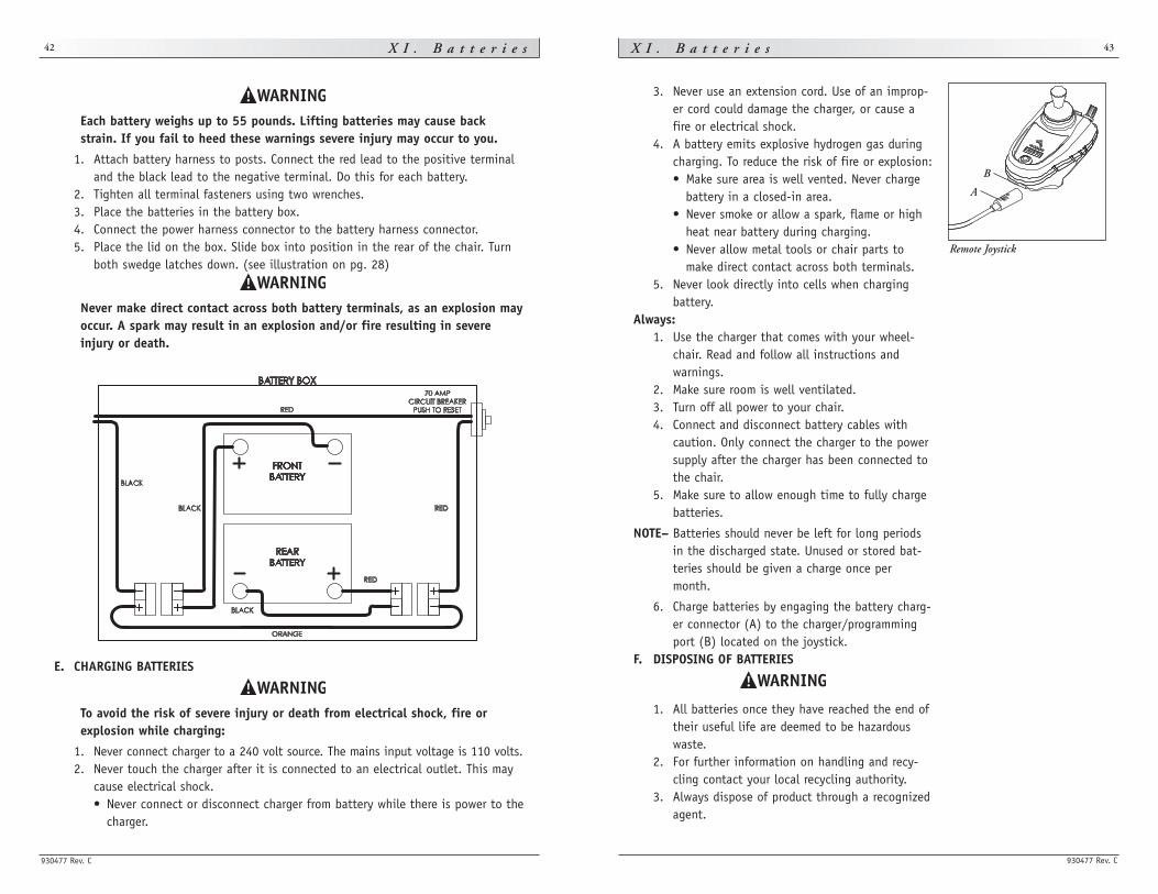
6. Charge batteries by engaging the battery charg-er connector (A) to the charger/programmingport (B) located on the joystick.
F. DISPOSING OF BATTERIES
1. All batteries once they have reached the end oftheir useful life are deemed to be hazardouswaste.
2. For further information on handling and recy-cling contact your local recycling authority.
3. Always dispose of product through a recognizedagent.
Remote Joystick
A
B
Each battery weighs up to 55 pounds. Lifting batteries may cause backstrain. If you fail to heed these warnings severe injury may occur to you.
1. Attach battery harness to posts. Connect the red lead to the positive terminaland the black lead to the negative terminal. Do this for each battery.
2. Tighten all terminal fasteners using two wrenches.3. Place the batteries in the battery box.4. Connect the power harness connector to the battery harness connector.5. Place the lid on the box. Slide box into position in the rear of the chair. Turn
both swedge latches down. (see illustration on pg. 28)
Never make direct contact across both battery terminals, as an explosion mayoccur. A spark may result in an explosion and/or fire resulting in severeinjury or death.
E. CHARGING BATTERIES
To avoid the risk of severe injury or death from electrical shock, fire orexplosion while charging:
1. Never connect charger to a 240 volt source. The mains input voltage is 110 volts.2. Never touch the charger after it is connected to an electrical outlet. This may
cause electrical shock.• Never connect or disconnect charger from battery while there is power to the
charger.
930477 Rev. C
X I I . M a i n t e n a n c e 45X I I . M a i n t e n a n c e
930477 Rev. C
44
D. BATTERY MAINTENANCE
1. To prevent an acid spill, always keep batteries upright (wet cell batteries).2. Never smoke or hold an open flame near batteries.3. Always wear rubber gloves and safety glasses when you handle batteries.
1. Maintenance Schedule:
This varies for different types of batteries. Always follow the instructions supplied withyour batteries.
NOTE– Always wear rubber gloves and safety glasses when you handle or service batteries.
2. Adding Water: (Wet Cells Only)• Wet-type lead acid batteries need periodic replacement of water.
NOTE– Use distilled water only.
• Check the battery fluid level about once a week. When you remove the stoppers(on top of the battery) there should be one-eighth to one-quarter of an inch of fluid above the internal plates. Do not overfill.
3. Corrosion:
Check battery terminals often for corrosion. a) If corrosion is present, use a wire brush to clean the terminals.
NOTE– Always wear safety glasses and rubber gloves.
b) Use baking soda to neutralize acid. c) Use petroleum jelly to re-grease the terminals after connecting cable to bat-
tery. (Completely cover the terminal nut and bolt, cable clip and any exposedcable with jelly).
4. For Answers To Questions: Contact your supplier.
A. NOTES
1. Proper maintenance will improve performance and extend the useful life of your chair.
2. Clean your chair regularly. This will help you find loose or worn parts and willmake your chair easier to use.
3. To protect your investment, have all major service and repair work done by your supplier.
1. Your chair needs regular maintenance for peak performance and to avoidinjury from chair failure, damage or premature wear.
2. Inspect and maintain this chair strictly per the “Maintenance Chart”.3. If you detect a problem, make sure to service or repair the chair before use.4. At least once a year, have a complete safety check and service of your
chair performed by a supplier.
B. CLEANING
1. Paint Finish: • Clean the paint finish with mild soapy water monthly. • Protect the paint with a coat of non-abrasive auto wax every three months.
2. Motors: • Clean around motor area weekly with a slightly damp (not wet) cloth. • Wipe off or blow away any fluff, dust, or dirt on or around the motors.
NOTE– You do not need to grease or oil the chair.
3. Upholstery: • Hand-wash only as needed. Machine washing may damage fabric. • Drip-dry only. Heat from a dryer may damage fabric.
NOTE– Washing the fabric may decrease fire retardant properties.
C. STORAGE TIPS
1. Store your chair in a clean, dry area. If you fail to do so, parts may rust or corrode. 2. Before using your chair, make sure it is in proper working order. Inspect and
service all items on the “Maintenance Chart”. 3. If you store this chair for more than three months, have it inspected by a
supplier before use.
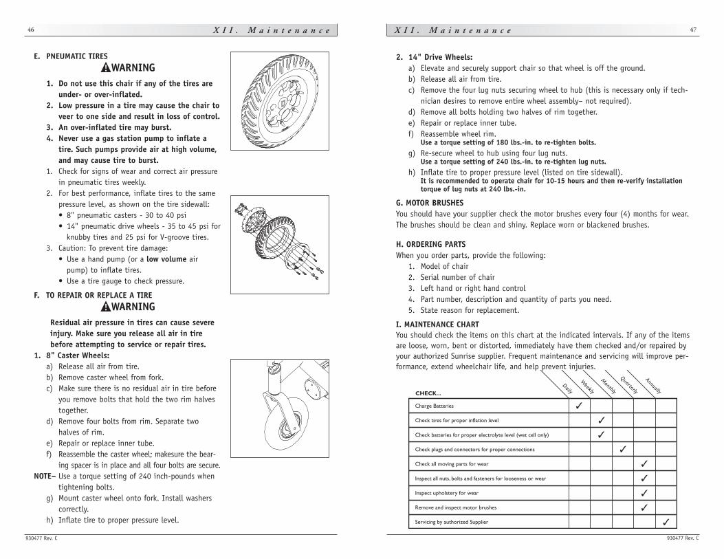
930477 Rev. C
X I I . M a i n t e n a n c e 47X I I . M a i n t e n a n c e
930477 Rev. C
46
2. 14" Drive Wheels: a) Elevate and securely support chair so that wheel is off the ground.b) Release all air from tire.c) Remove the four lug nuts securing wheel to hub (this is necessary only if tech-
nician desires to remove entire wheel assembly– not required).d) Remove all bolts holding two halves of rim together.e) Repair or replace inner tube.f) Reassemble wheel rim.
Use a torque setting of 180 lbs.-in. to re-tighten bolts.g) Re-secure wheel to hub using four lug nuts.
Use a torque setting of 240 lbs.-in. to re-tighten lug nuts.h) Inflate tire to proper pressure level (listed on tire sidewall).
It is recommended to operate chair for 10-15 hours and then re-verify installationtorque of lug nuts at 240 lbs.-in.
G. MOTOR BRUSHES You should have your supplier check the motor brushes every four (4) months for wear.The brushes should be clean and shiny. Replace worn or blackened brushes.
H. ORDERING PARTS When you order parts, provide the following:
1. Model of chair2. Serial number of chair3. Left hand or right hand control4. Part number, description and quantity of parts you need.5. State reason for replacement.
I. MAINTENANCE CHARTYou should check the items on this chart at the indicated intervals. If any of the itemsare loose, worn, bent or distorted, immediately have them checked and/or repaired byyour authorized Sunrise supplier. Frequent maintenance and servicing will improve per-formance, extend wheelchair life, and help prevent injuries.
E. PNEUMATIC TIRES
1. Do not use this chair if any of the tires areunder- or over-inflated.
2. Low pressure in a tire may cause the chair toveer to one side and result in loss of control.
3. An over-inflated tire may burst.4. Never use a gas station pump to inflate a
tire. Such pumps provide air at high volume,and may cause tire to burst.
1. Check for signs of wear and correct air pressurein pneumatic tires weekly.
2. For best performance, inflate tires to the samepressure level, as shown on the tire sidewall: • 8" pneumatic casters - 30 to 40 psi• 14" pneumatic drive wheels - 35 to 45 psi for
knubby tires and 25 psi for V-groove tires.3. Caution: To prevent tire damage:
• Use a hand pump (or a low volume airpump) to inflate tires.
• Use a tire gauge to check pressure.
F. TO REPAIR OR REPLACE A TIRE
Residual air pressure in tires can cause severeinjury. Make sure you release all air in tirebefore attempting to service or repair tires.
1. 8" Caster Wheels: a) Release all air from tire. b) Remove caster wheel from fork. c) Make sure there is no residual air in tire before
you remove bolts that hold the two rim halvestogether.
d) Remove four bolts from rim. Separate twohalves of rim.
e) Repair or replace inner tube. f) Reassemble the caster wheel; makesure the bear-
ing spacer is in place and all four bolts are secure. NOTE– Use a torque setting of 240 inch-pounds when
tightening bolts.g) Mount caster wheel onto fork. Install washers
correctly. h) Inflate tire to proper pressure level.
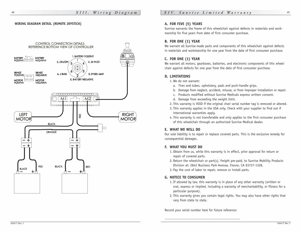
930477 Rev. C
X I V . S u n r i s e L i m i t e d W a r r a n t y 49X I I I . W i r i n g D i a g r a m
930477 Rev. C
48
A. FOR FIVE (5) YEARSSunrise warrants the frame of this wheelchair against defects in materials and work-manship for five years from date of first consumer purchase.
B. FOR ONE (1) YEARWe warrant all Sunrise-made parts and components of this wheelchair against defectsin materials and workmanship for one year from the date of first consumer purchase.
C. FOR ONE (1) YEARWe warrant all motors, gearboxes, batteries, and electronic components of this wheel-chair against defects for one year from the date of first consumer purchase.
D. LIMITATIONS1. We do not warrant:
a. Tires and tubes, upholstery, pads and push-handle grips.b. Damage from neglect, accident, misuse, or from improper installation or repair.c. Products modified without Sunrise Medicals express written consent.d. Damage from exceeding the weight limit.
2. This warranty is VOID if the original chair serial number tag is removed or altered.3. This warranty applies in the USA only. Check with your supplier to find out if
international warranties apply.4. This warranty is not transferable and only applies to the first consumer purchase
of this wheelchair through an authorized Sunrise Medical dealer.
E. WHAT WE WILL DOOur sole liability is to repair or replace covered parts. This is the exclusive remedy forconsequential damages.
F. WHAT YOU MUST DO1. Obtain from us, while this warranty is in effect, prior approval for return or
repair of covered parts.2. Return the wheelchair or part(s), freight pre-paid, to Sunrise Mobility Products
Division at: 2842 Business Park Avenue, Fresno, CA 93727-1328.3. Pay the cost of labor to repair, remove or install parts.
G. NOTICE TO CONSUMER1. If allowed by law, this warranty is in place of any other warranty (written or
oral, express or implied, including a warranty of merchantability, or fitness for aparticular purpose).
2. This warranty gives you certain legal rights. You may also have other rights thatvary from state to state.
Record your serial number here for future reference:
____________________________________________
WIRING DIAGRAM DETAIL (REMOTE JOYSTICK)

Sunrise Medical, Inc.7477 East Dry Creek Parkway • Longmont, Colorado • 80503 USA
(800) 333-4000
In Canada (800) 263-3390
© 2008, Sunrise Medical 8.08
930477 Rev. C