Embed Size (px)
Citation preview

11/15/2010
1
Successes in Accelerated BridgeSuccesses in Accelerated Bridge Construction
Mary Lou Ralls, P.E. Principal
Ralls Newman, LLC
(formerly Texas State Bridge Engineer)
1
Accelerated Bridge Construction (ABC) – Definition
Structural & geotechnical engineering g g gtechnologies that help agencies & the traveling public save time & money when bridge rehabilitation or reconstruction projects are implemented
2
Foundation & Wall Elements
Rapid Embankment Construction
Prefabricated Bridge Elements & Systems
Accelerated Bridge Construction Components
Structural Placement Methods
Fast Track Contracting
Reference: Federal Highway Administration (FHWA)
Continuous Flight Auger Piles
Geosynthetic Reinforced Soil (GRS) Integrated Bridge System
EPS GeofoamSystems
Prefabricated Elements- Superstructure- Substructure
Prefabricated Systems- Superstructure- Substructure- Total Bridge
Self-Propelled Modular Transporters (SPMTs)
Longitudinal launching
Horizontal sliding or skidding
Other heavy lifting equipment & methods
Innovative Contracting- Best value- CMGC
method- Design Build- A+B- A+B+C- Warranties
3
Prefabricated Bridge Elements & Systems (PBES) – Definition
Bridge structural components that g pare built off the bridge alignment to accelerate onsite construction time relative to conventional practice
4
Moving more of the cast‐in‐place construction to an off‐site location 5
How does PBES accelerate bridge construction?
Building the bridge first before youbefore you
set cones,
then quickly move it into place – like
in hours or a weekend!
11/15/2010
2
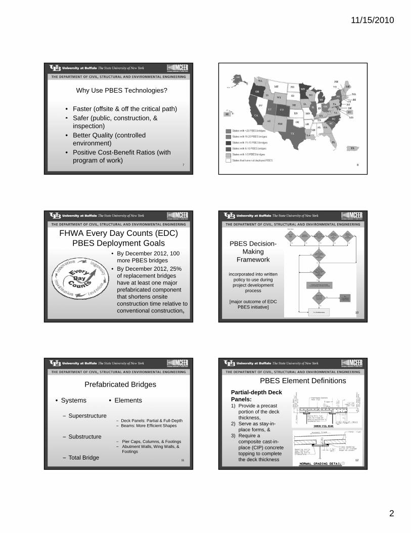
Why Use PBES Technologies?
• Faster (offsite & off the critical path)• Safer (public construction &Safer (public, construction, &
inspection)
• Better Quality (controlled environment)
• Positive Cost-Benefit Ratios (with program of work)
7 8
FHWA Every Day Counts (EDC) PBES Deployment Goals
• By December 2012, 100 more PBES bridges
• By December 2012, 25% of replacement bridges have at least one major prefabricated component that shortens onsite construction time relative to conventional construction9
PBES Decision-Making
Framework
incorporated into written policy to use during project development
process
[major outcome of EDC PBES initiative]
10
• Elements• Systems
S t t
Prefabricated Bridges
– Deck Panels: Partial & Full-Depth– Beams: More Efficient Shapes
– Pier Caps, Columns, & Footings– Abutment Walls, Wing Walls, &
Footings
– Superstructure
– Substructure
– Total Bridge 11
PBES Element Definitions
Partial-depth Deck Panels:1) Provide a precast
portion of the deck pthickness,
2) Serve as stay-in-place forms, &
3) Require a composite cast-in-place (CIP) concrete topping to complete the deck thickness 12

11/15/2010
3
Partial-Depth Deck Panels
13
PBES Element Definitions
Full-depth Deck Panels:
• Prefabricated the full thickness & do not require CIP concrete to complete the deck thickness
• May include concrete, steel, fiber-reinforced polymers, & aluminum
• Overlays may be included
Precast Decks on Steel Framing
Precast Decks on PS Beams
14
George Washington Memorial Parkway, VA – 2002
Replaced deck while
keeping bridge open
to traffic on weekdays 15
Live Oak Creek Bridge, TX – 2008
Erection of deck panels over shear studs on beams
Panels after erection on
Panels designed per NCHRP 12-65,“Full-Depth, Precast-Concrete Deck Panel Systems” – no post-tensioning or overlay
700-ft long, 32-ft wide bridge
86 full-depth, full-width
deck panels, totaling
22,400 sq ft 16
chloride penetrability7-day and Overnight Cure Closure Pour Materials
bond
shrinkage
freeze-thaw durability
Materials
Ref.: NCHRP 10-7117
Fiber-Reinforced Polymer (FRP) Decks
18

11/15/2010
4
Rt. 24 Bridge over Deer Creek, MD – 2001
122.5-ft long, 33-ft wide historic through-truss bridge
FRP deck replacement19
PBES Element DefinitionsBeams/More Efficient Shapes: Beams with innovative shapes
eliminating a construction
activity i e :activity, i.e.:
• Spread precast spliced tub girders
• Adjacent precast beams w/CIP deck
• Adjacent inverted tee beams with
full or partial CIP deck
• Adjacent decked bulb tees with
partial CIP decks
NEXT Beams
20
NCHRP 10-71 – PrecastComposite Slab Span System (PCSSS)based on French Poutre Dalle System from 2004 FHWA International
Scanning Tour
• Span to Depth: 1/28 - 1/30
• Span lengths: 20 ft to 60 ft• Span lengths: 20 ft to 60 ft
(45-ft span – 20-in depth)
• Minimum CIP depth 6 in
• Place ~12 beams in 4 hrs
Reference: NCHRP 10-71, C. French, C. K. Shield, Univ of Minnesota; & Z. J. Ma, Univ of Tenn - Knoxville
21
NCHRP 10-71PCSSS Initial Implementation
Roughened Surfaces
Inverted T Precast Sections
Horizontal and Vertical Shear Reinforcement
8 to 22”
Chamfered Corners
90oTransverse Hook to facilitate “drop-in” cage
Prestressing Tendons
ConstantVariable w/ span length
Constant 6” CIP thickness
Constant 3”
22
NCHRP 10-71 Construction
Center City Bridge (3 span: 22-27-22 ft)
23
PBES Element DefinitionsPier Cap, Column,
and/or Footing: A combination of precast & CIP
concrete interior support elements i econcrete interior support elements, i.e.,
1) Precast pier cap with CIP column(s)
2) Precast pier cap & precast column(s) with CIP pile cap footing, or
3) Precast spread footing with CIP column(s)
Precast piers
Precast pier cap24

11/15/2010
5
Precast Concrete Piers
Precast pier cap
SH 66 over Lake Belton Bridge, Texas
25
Grouted Duct and Cap Pocket Details - Seismic
Grouted Duct
Cap Pocket, Full Ductility (CPFD)
Elevation
Plan Cap Pocket, Limited Ductility (CPLD)
Elevation
Cap
Section ElevationIsometric View of Joint
Ref.: NCHRP 12-7426
NCHRP 12-74 Lateral Load-Displacement for All Specimens
Source: Eric Matsumoto, California State University, Sacramento27
NCHRP 12-74Hysteretic Response
Cast-in-place
Grouted Duct
Cap Pocket,Full Ductility
28
Abutment Wall, Wingwall, and/or Footing: 1) A combination of precast & CIP
concrete abutment elements, i.e., a) Precast abutment wall with
PBES Element Definitions
a) Precast abutment wall withCIP wingwalls,
b) Precast abutment wall &precast wingwalls withCIP footing,
c) Precast footing withCIP abutment wall; or
2) Geosynthetic reinforced soil (GRS) abutment
Precast Cantilever Abutments
29
Mill Street Bridge over Lamprey River, NH – 2004
Placing spread footing segments
Prefabricated HPCSubstructure:10 footing segments11 abutment and
wingwall segments
Precast reinforced concrete substructureafter erection, prior to placing backfill
30

11/15/2010
6
PBES System DefinitionsSuperstructure: 1) Adjacent slab & box beams
w/o CIP deck with or w/o overlay,
2) Deck bulb tee beams w/o2) Deck bulb tee beams w/o CIP deck with or w/o overlay,
3) Composite units with or w/o overlay,
4) Precast segmental box segments,5) Truss spans and arch spans constructed off the
bridge alignment, or6) Total superstructures moved in with SPMTs,
skidded, or launched
Superstructure Span on SPMT
31
143-ft long, 59-ft wide1,300-ton replacement spans built in adjacent staging area
Graves Avenue Bridge over I-4, FL – 2006
Half-hour rolling roadblocks on I-4 to remove 71-ft long, 30-ft wide, 250-ton spans 32
Each new span installed in few hours overnight
Graves Avenue Bridge over I-4, FL – 2006
I-4 closed two partial nights for installations
33
GravesAvenueB idBridge,
FL –2006
34
4500 South Bridge over I-215E, UT - 2007Prefabricated Superstructuredriven into position with SPMTs
• I-215 closed over a weekend• 4500 South closed only 10 days
35
I-80 State Street to 1300 EastMultiple Structures, UT - 2008
I-80W over Highland Drive
I-80W over 900 East Street
I-80W over 700 East Street
I-80W over 500 East Street
I-80W over 300 East Street
I-80W 600 East Ramp Bridge
I-80W over 600 East Street
36

11/15/2010
7
I-80 State Street to 1300 East – Bridge Farm
37
US 15/29 Bridge over Broad Run, VA – 2008 Superstructure Replacement & Roadway Widening
38 Existing Bridge Elevation
Typical Sections
Existing Bridge
[Exterior Edge]
[Median]
2’-6 ½” 28’-0” 2’-6 ½”
2 Lanes @ 12’-0” + 2 Shoulders @ 2’-0”
Widen 5’- 4”
3’-2 ½”3’-2 ½” 8’-10” 9’-0” 8’-10”
Proposed Modular Bridge
36’- 0” Roadway1’- 3” 1’- 3”
7’-10” 8’- 9” 9’-0” 12’-11”
8’-0”Shoulder
12’ Lane 12’ Lane
4’-0”Shoulder
39
Revised Construction of Span ASpan A Span B Span C
Detour SB Traffic
40
Detour SB TrafficDuring Weekend
[Median]
Remove/ReplaceSuperstructure
Steel Beams: Galvanization & Shipping
41Steel beams after galvanizing & shipment to
Coastal Precast Systems, Inc.
Prefabricating Modular Deck Units
42

11/15/2010
8
Revised Construction SequenceRevised Maintenance-of-Traffic Plan for Weekend Closures
4344
Placing Asphalt at Abutment & Sealing Deck Joints
45
Completed Structure with Asphalt Overlay
46
PBES System Definitions
Substructure: Bridges with:
1) Non-prefab deck or superstructuresuperstructure,
2) Prefab interior supports that are connected to precast or CIP foundations if multiple span, &
3) Precast or CIP abutments Precast Integral
Abutments 47
Newark Airport Monorail, NJ
Steel Substructure
48

11/15/2010
9
I-287 Cross Westchester Viaduct, NY – 1999
PrecastConcrete
Substructure
49
PBES System DefinitionsTotal Bridge:1) Bridges with:
a) Superstructure as defined above or superstructure consisting of spread prefab beams & prefab deck,
b) Prefab interior supports that are connected to precast or CIP foundations if multiple span &precast or CIP foundations if multiple span, &
c) Precast or CIP abutments;
2) Prefabricated culverts that
meet the National Bridge
Inventory (NBI) definition, or
3) Geosynthetic reinforced soil
(GRS) integrated bridge system
Everything shown can be prefabricated
Total Bridge Prefabrication50
SH 86 over Mitchell Gulch Bridge, CO – 2002
40-ft long, 43-ft widesingle-span bridgereplaced over aweekend
No impact topeak-hour traffic
weekend
51
Belt Pkwy. over Ocean Pkwy. Bridge, NY- 2004
2-span, 149-ft long,78-ft wide bridge to 3-span, 221-ft long, 134-ft wide bridge
No lane closures during peak-hour traffic
3 de b dge
52
FHWA Geosynthetic Reinforced Soil (GRS) Integrated Bridge System (IBS)
2009 Nova Award for Construction Innovation53
GRS IBS Construction OverviewReinforced Soil Foundation
Wall Construction
Beam Placement
4 years later
54

11/15/2010
10
How is PBES installed?
• Self-Propelled Modular Transporters (SPMTs)
• Longitudinal launchingLongitudinal launching
• Horizontal sliding or skidding
• Other heavy lifting equipment & methods
• Conventional lifting equipment & methods
55
CTA Wells Street Bridge, IL – 2002
111-ft long, 25-ft high, 425-ton truss span installed over a weekend56
I-195 Providence River Bridge, RI – 2006
57
Network Arch:• 400-ft long• 165-ft wide• 10º skew
Assembled in staging area & barged tosite on SPMTs 58
Continuous Launching
59
Fort Lane/I-15 South Layton Interchange, UT – 2010
Longitudinal Launching
60

11/15/2010
11
Fort Lane/I-15 South Layton Interchange
61
Transverse Launching
62
I-80E Bridge at 2300E, UT – 2009
TransverseSliding
Easy Site Conditions
I-80W Bridge at 2300EDifficult Site Conditions
63
Church Street Bridge, CT – 2003Erected in hours over a weekend night to minimize rail disruption
320-ft, 850-ton steeltruss center spanover New HavenRail Yard
64
I-95 over James River Bridge, VA – 2002
102 superstructure spans replaced with no lane closures during peak traffic
65
Benefits of Using PBES for ABC
• Reduced onsite construction time• Minimized traffic disruption – months to
days• Reduced environmental impact• Improved worker & motorist safety • Improved constructability• Increased product quality – controlled
environment, cure times, easier access, …
66

11/15/2010
12
Reduces Onsite Construction Time
• Less time spent onsite
• Traditional tasks can beTraditional tasks can be done offsite
• Minimal impact from weather conditions
Minimizes Traffic Impacts
Minimizes traffic delay & community disruption
I-59 and I-65 Interchange, AL
Reduces detours, lane closures, & narrow lanes
US 59 under Dunlavy, TX
68
Minimizes environmental impact
• Keeps heavy equipment out q pof sensitive environments
• Shortens construction season
Linn Cove Viaduct, NC
Improves Work Zone Safety• Reduces onsite
construction time
Mi i i k• Minimizes work near traffic and power lines, at high elevations, or over water
Meylan Pedestrian Bridge, France 70
Improves Constructability
• Prefabricated elements & systems– Minimized impact
from environmental constraints
– Less work over water, near power lines, …
San Mateo-Hayward Bridge, CA
Increases quality
• Prefabricated in a controlled environment
• Increases quality control• Increases quality control
George P. Coleman Bridge, VA –1995 72

11/15/2010
13
PBES: Improves Quality & Lowers Life-Cycle Costs – to “Stay Out”
• Controlled environmentR d d d d th– Reduced dependence on weather
– Established materials suppliers for consistent quality of materials
– Standardized plant operations for consistent quality of production
– Optimum concrete curing73
Is PBES more cost-effective?
• Depends on type of structure & elements or systems used
• Many systems can cost less than y yconventional construction
• First implementation of new components frequently costs more
• Need a program of projects for economy of scale
74
Declining Cost of Deploying Innovative Technology
• First use typically costs more
• Potential for new methods to cost less
• Promise of time savings
• Positive cost-benefit ratios
• Promise of programmatic cost savings 75
Full-Depth Precast Deck Costs in Utah
76
SPMT Bridge Move Costs in Utah
77
Accelerated Bridge Construction Decision Making & Economic Modeling Tool
Transportation Pooled Fund Study TPF-5(221)
P j t St t D t D b 2009Project Start Date: December 2009
Project End Date: June 2011
Participating: Oregon (lead), California, Iowa, Minnesota, Montana, Texas, Utah, Washington, FHWA
PI: Toni Doolen, Oregon State University 78

11/15/2010
14
Task 3: Develop Models• Develop decision tree & economic
modeling tool for ABC vs conventional construction
• Test & validate model using data from previously-completed ABC projects
• Use MS Visual Basic .NET to create tool incorporating model
• Create user’s guide & training materials79
ABC Decision Making & Economic Modeling Tool
Based on Analytical Hierarchy Process (AHP)
• Evaluates various alternative construction• Evaluates various alternative construction strategies by considering both quantitative & qualitative criteria
• Uses paired comparisons for relative importance
• Considers tangible & intangible factors80
Survey Form
• AHP survey scale is based on previous research & is well-developed, tested, &
lid t d ( S t 1990)validated (e.g., Saaty, 1990)
• AHP survey contains a series of pair-wise comparisons between criteria located at each level of a decision hierarchy
81
Decision Hierarchy
82
Survey Form – Level 1
83
Oregon’s Elk Creek Project
• Project Stage: Completed
• Best Alternative: ABC
84
• Critical Factors: Site Constraints & Work Windows

11/15/2010
15
Accelerated Bridge Construction Decision Making & Economic Modeling Tool
Transportation Pooled Fund Study TPF-5(221)
P j t MProject Manager:
Benjamin Tang, P.E.
Oregon Department of Transportation
Phone: 503-986-3324
Email: [email protected]
85
Questions
1. What are the five major components of accelerated bridge construction (ABC)?
2. What is the definition of prefabricated bridge elements or systems (PBES)?
3. What are the different factors to consider when determining whether to use ABC or conventional construction?
86
Questions
4. Which parts of a bridge can be prefabricated?
5. What are the benefits of using PBES?
6. What are some of the structural placement methods that can be used to move a bridge or bridge component?
87
Open-Ended Questions
1. Evaluate the cost effectiveness of using accelerated bridge construction techniques versus conventional construction.
2. For what types of bridge projects would you consider using self-propelled modular transporters?
88
Thank You
89


![5 roadblocks webinar [slides]](https://img.pdfslide.net/doc/110x75/58ed95061a28ab7f1b8b45bb/5-roadblocks-webinar-slides.jpg)