Embed Size (px)
Citation preview

8/3/2019 Rapier Family Qig g v261
http://slidepdf.com/reader/full/rapier-family-qig-g-v261 1/12
RAPIER SWITCH
QUICK INSTALL GUIDE

8/3/2019 Rapier Family Qig g v261
http://slidepdf.com/reader/full/rapier-family-qig-g-v261 2/12
Rapier Switch Quick Install Guide
Document Number C613-04017-01 REV G.
Copyright © 1999-2003 Allied Telesyn International, Corp.
19800 North Creek Parkway, Suite 200, Bothell, WA 98011, USA.
All rights reserved. No part of this publication may be reproduced without prior written
permission from Allied Telesyn.
Allied Telesyn International, Corp. reserves the right to make changes in specifications
and other information contained in this document without prior written notice. The
information provided herein is subject to change without notice. In no event shall Allied
Telesyn be liable for any incidental, special, indirect, or consequential damages
whatsoever, including but not limited to lost profits, arising out of or related to this
manual or the information contained herein, even if Allied Telesyn has been advised of,
known, or should have known, the possibility of such damages.
All trademarks are the property of their respective owners.
8/3/2019 Rapier Family Qig g v261
http://slidepdf.com/reader/full/rapier-family-qig-g-v261 3/12
Quick Install Guide 3
C613-04017-01 REV G
Models Covered By This Guide
This Quick Install Guide includes information on the following models:
■ Rapier G6
■ Rapier G6F-LX/SC
■ Rapier G6F-SX/SC
■ Rapier G6F-SX/MT
■ Rapier 8/8MT
■ Rapier 8/8SC
■ Rapier 16F-FX/MT
■ Rapier 16Fi-FX/MT
■ Rapier 16F-FX/SC
■ Rapier 16Fi-FX/SC
■ Rapier 24
■ Rapier 24i
■ Rapier 48
■ Rapier 48i
Quick Install Guide updates can be downloaded fromwww.alliedtelesyn.co.nz/support/rapier/.
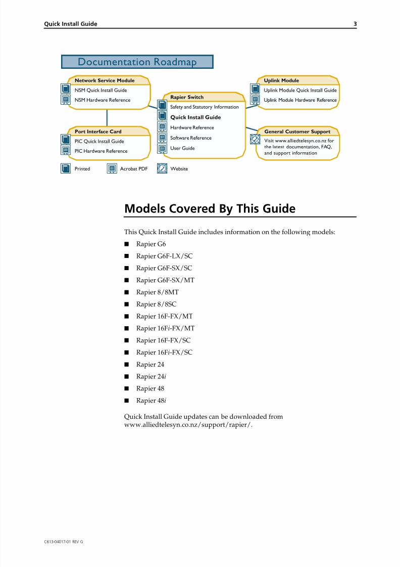
Rapier SwitchSafety and Statutory Information
Quick Install Guide
Hardware Reference
Software Reference
Network Service Module
NSM Quick Install Guide
NSM Hardware Reference
Port Interface Card
PIC Quick Install Guide
PIC Hardware Reference
General Customer Support
Visit www.alliedtelesyn.co.nz for
the latest documentation, FAQ,
and support information
Uplink Module
Uplink Module Quick Install Guide
Uplink Module Hardware Reference
Printed Acrobat PDF Website
Documentation Roadmap
User Guide
8/3/2019 Rapier Family Qig g v261
http://slidepdf.com/reader/full/rapier-family-qig-g-v261 4/12
4 Rapier Switch
C613-04017-01 REV G
Package Contents
The following items are included with each Rapier Switch. Contact your salesrepresentative if any items are damaged or missing.
■ One Rapier Switch.
■ One AC power cord (AC models only).
■ One serial cable for connecting the switch to a terminal or PC.
■ One 19 inch rack-mount kit.
■ One Rapier Switch Quick Install Guide.
■ One Safety and Statutory Information booklet.
■ One Rapier Switch Documentation and Tools CD-ROM (which includesthe complete Rapier Document Set and utilities).
■ One warranty card.
Selecting a Site
The switch can be installed in a standard 19-inch rack or on a level surface suchas a desktop or bench. When installing the switch, choose a site that:
■ Allows adequate airflow around the switch and its vents.
■ Is free of dust and moisture.
■ Will maintain an ambient temperature range of 0-40º C (32-104º F) and a
humidity range of 5-95% non-condensing.■ Has a reliable and earthed (grounded) power supply circuit, preferably
dedicated and filtered.
■ Does not expose cabling to sources of electrical noise, such as radiotransmitters, broadband amplifiers, power lines, electric motors, andfluorescent fixtures.
■ Allows easy access to the switch’s power and cable connections.
■ Will allow all related network devices to be connected to the switchwithout exceeding maximum cable length limitations. See the Rapier Switch Hardware Reference for cable length specifications.
8/3/2019 Rapier Family Qig g v261
http://slidepdf.com/reader/full/rapier-family-qig-g-v261 5/12
Quick Install Guide 5
C613-04017-01 REV G
Installing the Switch
All AC and DC versions of this equipment must be earthed.
Follow these steps to install the switch:
1. Before installing the switch, read the safety information
For safety information, see the Safety and Statutory Information booklet. Acopy of this booklet is supplied with each switch, and can also be found onthe Documentation and Tools CD-ROM or at www.alliedtelesyn.co.nz/support/rapier/.
2. Gather the tools and equipment you will need
If installing a DC version of the switch, you will need a DC power source,DC supply cable, and wire strippers (see step 7).
If the switch is to be connected to a redundant power supply, you will needa redundant power supply unit and cable (see step 9).
3. Unpack the switch
Verify the package contents. If any items are damaged or missing, contactyour sales representative.
4. Install expansion options
If you purchased optional Uplink Modules, a Network Service Module(NSM), or Port Interface Cards (PICs), install them now by following theirindividual installation guides. These guides can be found on the
Documentation and Tools CD-ROM.
5. Place the switch in its operating location
See the previous "Selecting a Site" section for guidelines on choosing asuitable location. If installing the switch in a rack:
• Remove the rubber feet.
• Attach the rack-mounting brackets.
• Mount the switch in the rack.
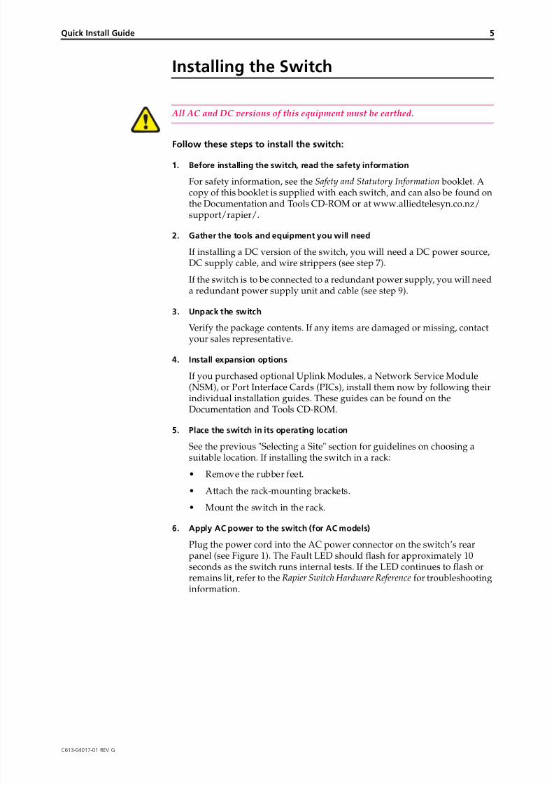
6. Apply AC power to the switch (for AC models)
Plug the power cord into the AC power connector on the switch’s rearpanel (see Figure 1). The Fault LED should flash for approximately 10seconds as the switch runs internal tests. If the LED continues to flash orremains lit, refer to the Rapier Switch Hardware Reference for troubleshootinginformation.
8/3/2019 Rapier Family Qig g v261
http://slidepdf.com/reader/full/rapier-family-qig-g-v261 6/12
6 Rapier Switch
C613-04017-01 REV G
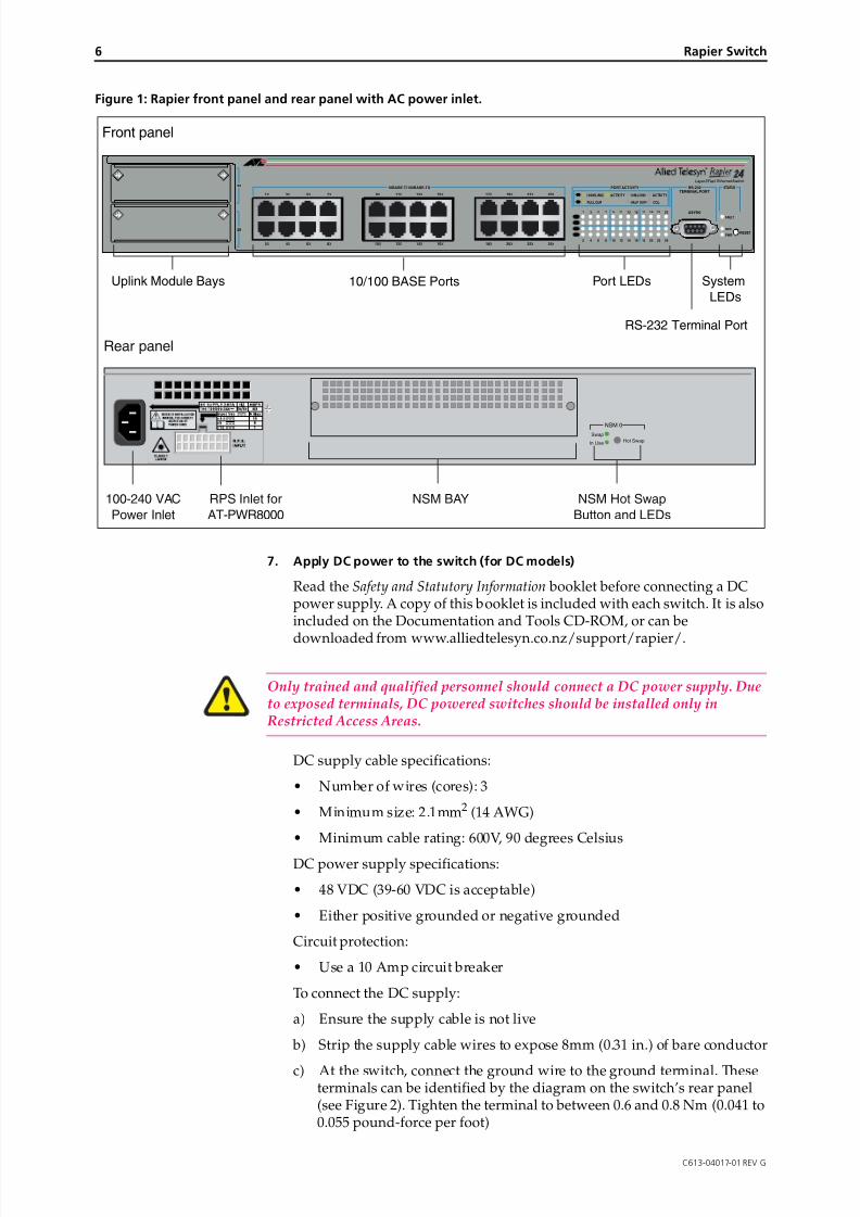
Figure 1: Rapier front panel and rear panel with AC power inlet.
7. Apply DC power to the switch (for DC models)
Read the Safety and Statutory Information booklet before connecting a DCpower supply. A copy of this booklet is included with each switch. It is alsoincluded on the Documentation and Tools CD-ROM, or can be
downloaded from www.alliedtelesyn.co.nz/support/rapier/.
Only trained and qualified personnel should connect a DC power supply. Dueto exposed terminals, DC powered switches should be installed only inRestricted Access Areas.
DC supply cable specifications:
• Number of wires (cores): 3
• Minimum size: 2.1mm2 (14 AWG)
• Minimum cable rating: 600V, 90 degrees Celsius
DC power supply specifications:
• 48 VDC (39-60 VDC is acceptable)
• Either positive grounded or negative grounded
Circuit protection:
• Use a 10 Amp circuit breaker
To connect the DC supply:
a) Ensure the supply cable is not live
b) Strip the supply cable wires to expose 8mm (0.31 in.) of bare conductor
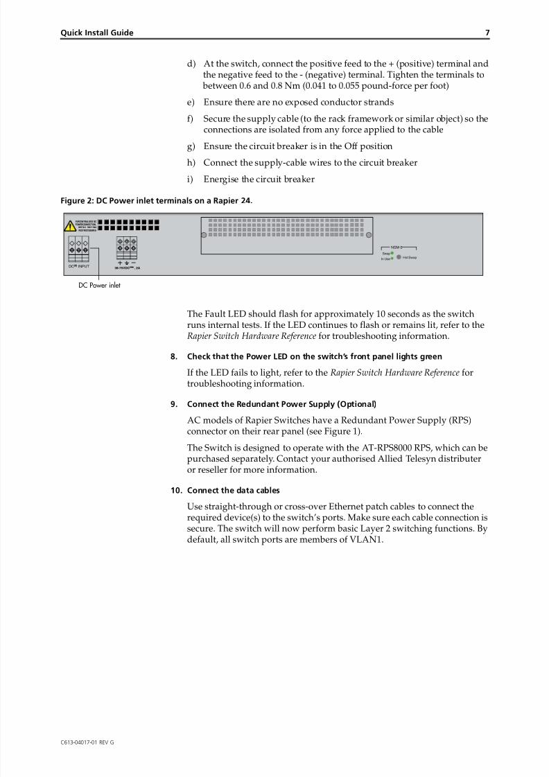
c) At the switch, connect the ground wire to the ground terminal. Theseterminals can be identified by the diagram on the switch’s rear panel(see Figure 2). Tighten the terminal to between 0.6 and 0.8 Nm (0.041 to0.055 pound-force per foot)
STATUS
RESET
FAULT
PWR
RPS
1
2
3
4
5
6
7
8
9
10
11
12
13
14
15
16
17
18
19
20
21
22
23
24
10BASE-T / 100BASE-TX
1X 3X 5X 7X
2X 4X 6X 8X
9X 11X 13X 15X
10X 12X 14X 16X
17X 19X 21X 23X
18X 20X 22X 24X
25
26
RS-232
TERMINAL PORT
100M LINK / ACTIVITY 10M LINK / ACTIVITY
HALF DUP/ COLFULL DUP
PORT ACTIVITY
L/A
L/A
D/C
D/C
L/A
D/C
ASYN0
Layer 3 Fast Ethernet Switch
NSM 0
Hot SwapIn Use
Swap
Front panel
Uplink Module Bays 10/100 BASE Ports Port LEDs System
LEDs
RS-232 Terminal Port
Rear panel
100-240 VAC
Power Inlet
RPS Inlet for
AT-PWR8000
NSM BAY NSM Hot Swap
Button and LEDs
8/3/2019 Rapier Family Qig g v261
http://slidepdf.com/reader/full/rapier-family-qig-g-v261 7/12
Quick Install Guide 7
C613-04017-01 REV G
d) At the switch, connect the positive feed to the + (positive) terminal andthe negative feed to the - (negative) terminal. Tighten the terminals to between 0.6 and 0.8 Nm (0.041 to 0.055 pound-force per foot)
e) Ensure there are no exposed conductor strands
f) Secure the supply cable (to the rack framework or similar object) so theconnections are isolated from any force applied to the cable
g) Ensure the circuit breaker is in the Off position
h) Connect the supply-cable wires to the circuit breaker
i) Energise the circuit breaker
Figure 2: DC Power inlet terminals on a Rapier 24.
The Fault LED should flash for approximately 10 seconds as the switchruns internal tests. If the LED continues to flash or remains lit, refer to the Rapier Switch Hardware Reference for troubleshooting information.
8. Check that the Power LED on the switch’s front panel lights green
If the LED fails to light, refer to the Rapier Switch Hardware Reference fortroubleshooting information.
9. Connect the Redundant Power Supply (Optional)AC models of Rapier Switches have a Redundant Power Supply (RPS)connector on their rear panel (see Figure 1).
The Switch is designed to operate with the AT-RPS8000 RPS, which can bepurchased separately. Contact your authorised Allied Telesyn distributeror reseller for more information.
10. Connect the data cables
Use straight-through or cross-over Ethernet patch cables to connect therequired device(s) to the switch’s ports. Make sure each cable connection issecure. The switch will now perform basic Layer 2 switching functions. By
default, all switch ports are members of VLAN1.
NSM 0
Hot SwapIn Use
Swap
38-75VDC , 2A
FORCENTRALIZED DCPOWERCONNECTION,
INSTALL ONLY INA
RESTRICTEDAREA
DC Power inlet
DC INPUT
8/3/2019 Rapier Family Qig g v261
http://slidepdf.com/reader/full/rapier-family-qig-g-v261 8/12
8 Rapier Switch
C613-04017-01 REV G
Configuring the Switch
Some configuration is necessary if you wish to enable the switch’s advancedswitching capabilities. The switch can be configured by using the CommandLine Interface (CLI) or Graphical User Interface (GUI).
Using the CLI to configure a switch
1. Connect a terminal or PC to the Terminal Port (ASYN0)
Using the supplied RS-232 DB9 straight-through cable, connect a VT100-compatible terminal or the COM port of a PC running a terminalemulation program such as Windows Terminal, to the RS-232 TerminalPort on the switch’s front panel.
2. Set the communication parameters
Set the communication parameters on your terminal or terminal emulationprogram to:
• Baud rate: 9600
• Data bits: 8
• Parity: None
• Stop bits: 1
• Flow control: Hardware
3. Log in and set the password
After the switch has booted, the log-in prompt appears. If the log-inprompt doesn’t appear, press [Enter] two or three times.
When the switch boots for the first time it automatically creates an accountwith manager privileges. The account has the log in name “manager” andthe password is “friend”.
At the log in prompt, enter the log in name and password.
Login: manager
Password: friend
The switch’s command prompt appears and you can now configure theswitch using the command line interface.
Change the password as soon as possible. Leaving the manager account with
the default password is a serious security risk. Make sure you remember thenew password as there is no way to retrieve it if it is lost.
Use the following command to change the account password:
set password
The Command Help lists available commands for each protocol, and theirsyntax. To display a list of help topics, enter:
help
To display help on a specific topic, enter:
help topic
Alternatively, type a question mark (?) at the end of a partially completedcommand to see a list of valid options.
8/3/2019 Rapier Family Qig g v261
http://slidepdf.com/reader/full/rapier-family-qig-g-v261 9/12
Quick Install Guide 9
C613-04017-01 REV G
See the Rapier Switch Software Reference for more information on start-upand configuration procedures (including a list of message definitions).
Using the GUI to configure a switch
This section describes how to access the GUI from a PC via VLAN1, inorder to configure the switch. It assumes that the PC and the switch are in
the same subnet. By default, all switch ports are members of VLAN1.
The GUI requires a PC and web browser. Supported browsers are InternetExplorer 5.0 and greater, or Netscape 6.2.2 or 6.2.3, with JavaScript enabled.Internet Explorer can be found on the Documentation and Tools CD-ROMthat is bundled with your switch.
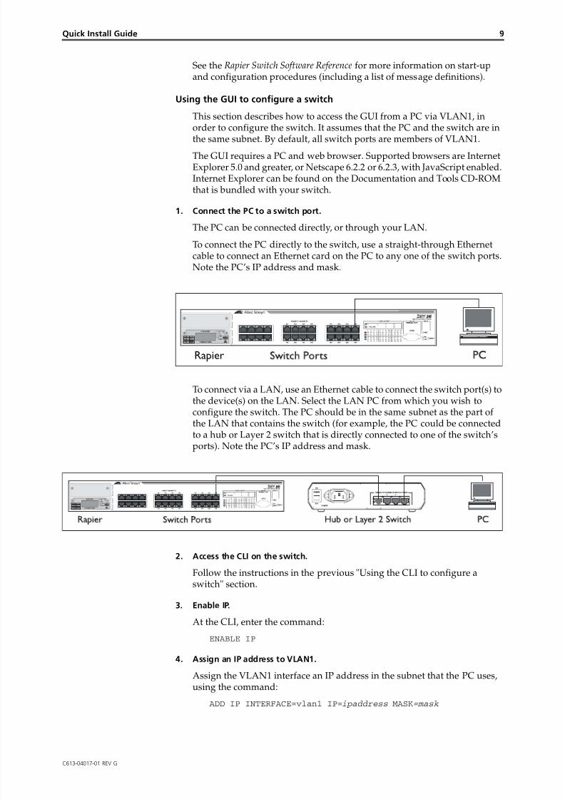
1. Connect the PC to a switch port.
The PC can be connected directly, or through your LAN.
To connect the PC directly to the switch, use a straight-through Ethernetcable to connect an Ethernet card on the PC to any one of the switch ports.Note the PC’s IP address and mask.
To connect via a LAN, use an Ethernet cable to connect the switch port(s) tothe device(s) on the LAN. Select the LAN PC from which you wish toconfigure the switch. The PC should be in the same subnet as the part ofthe LAN that contains the switch (for example, the PC could be connectedto a hub or Layer 2 switch that is directly connected to one of the switch’sports). Note the PC’s IP address and mask.
2. Access the CLI on the switch.Follow the instructions in the previous "Using the CLI to configure aswitch" section.
3. Enable IP.
At the CLI, enter the command:
ENABLE IP
4. Assign an IP address to VLAN1.
Assign the VLAN1 interface an IP address in the subnet that the PC uses,using the command:
ADD IP INTERFACE=vlan1 IP=ipaddress MASK=mask
Rapier
8/3/2019 Rapier Family Qig g v261
http://slidepdf.com/reader/full/rapier-family-qig-g-v261 10/12
10 Rapier Switch
C613-04017-01 REV G
5. Browse to the GUI.
If you access the Internet through a proxy server, set your browser to bypass the proxy for the IP address you just assigned to the VLAN1interface.
Point your web browser at the IP address of the VLAN interface.
6. Log in and set the password.
At the log in prompt, enter the log in name and password. Passwords arecase sensitive.
User Name: manager
Password: friend
The system status page appears and you can now use the GUI to configurethe switch.
To ensure configuration settings are saved correctly, use the GUI menus and buttons tonavigate, not your browser’s buttons.
As a security precaution, change the password as soon as possible.
To change the password, select Management > Users from the sidebarmenu. Select the Manager account and click Modify.
7. To access context-sensitive help in the GUI.
Click on the Help Button [Help]. The Help button is located at the top ofthe sidebar menu or on any popup page.
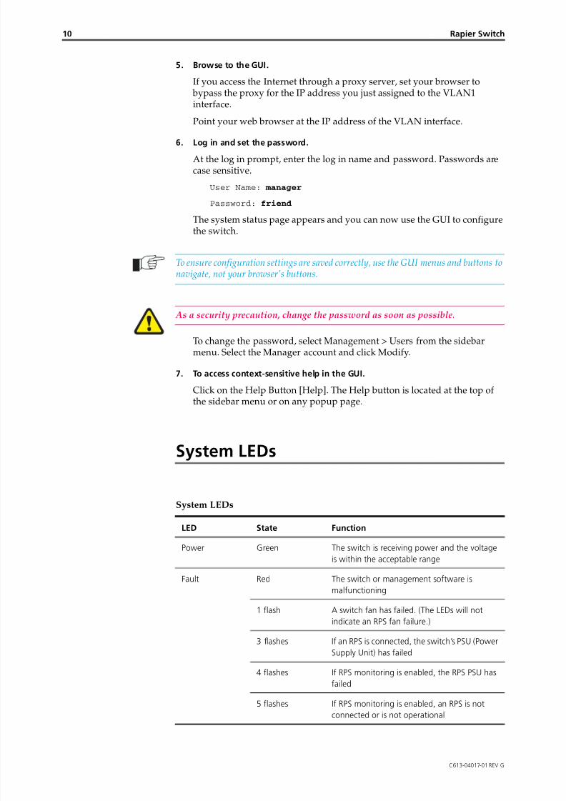
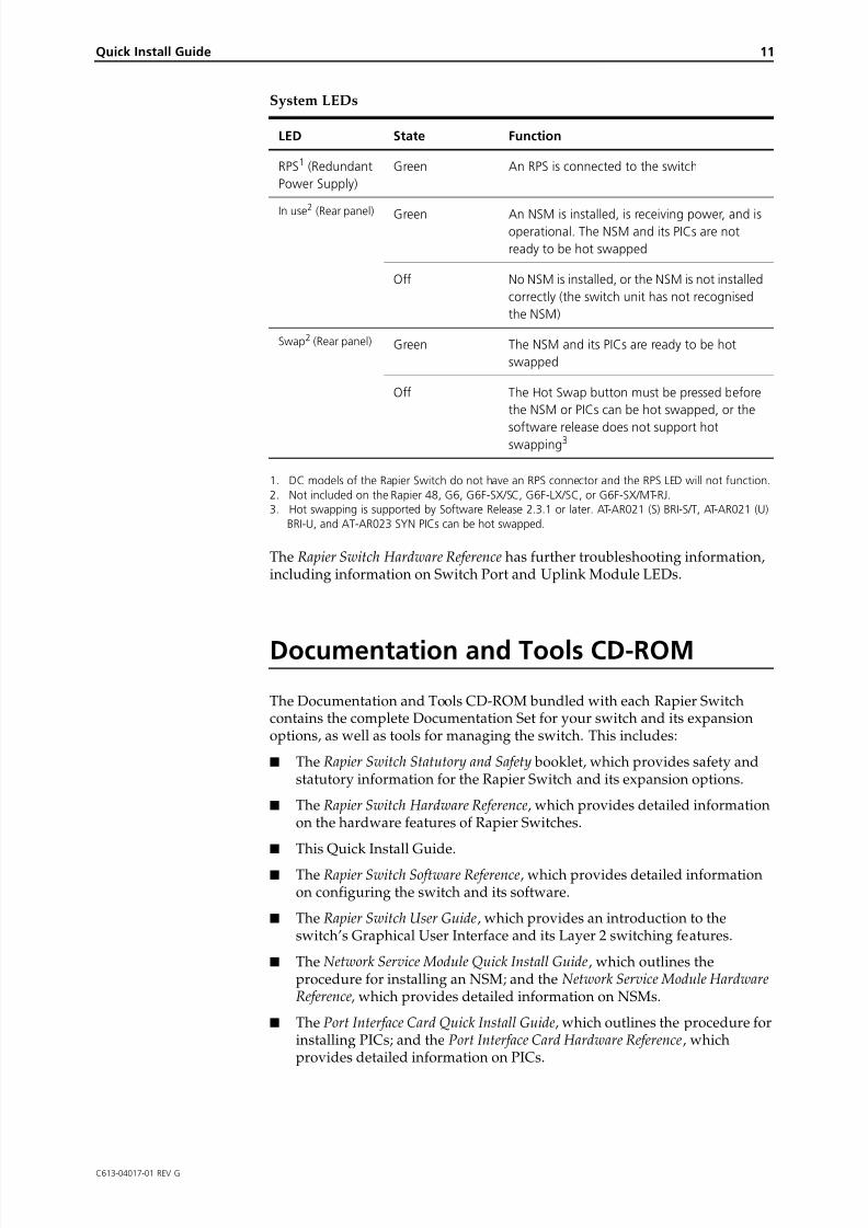
System LEDs
System LEDs
LED State Function
Power Green The switch is receiving power and the voltage
is within the acceptable range
Fault Red The switch or management software is
malfunctioning
1 flash A switch fan has failed. (The LEDs will not
indicate an RPS fan failure.)
3 flashes If an RPS is connected, the switch’s PSU (Power
Supply Unit) has failed
4 flashes If RPS monitoring is enabled, the RPS PSU has
failed
5 flashes If RPS monitoring is enabled, an RPS is notconnected or is not operational
8/3/2019 Rapier Family Qig g v261
http://slidepdf.com/reader/full/rapier-family-qig-g-v261 11/12
Quick Install Guide 11
C613-04017-01 REV G
1. DC models of the Rapier Switch do not have an RPS connector and the RPS LED will not function.
2. Not included on the Rapier 48, G6, G6F-SX/SC, G6F-LX/SC, or G6F-SX/MT-RJ.
3. Hot swapping is supported by Software Release 2.3.1 or later. AT-AR021 (S) BRI-S/T, AT-AR021 (U)
BRI-U, and AT-AR023 SYN PICs can be hot swapped.
The Rapier Switch Hardware Reference has further troubleshooting information,including information on Switch Port and Uplink Module LEDs.
Documentation and Tools CD-ROM
The Documentation and Tools CD-ROM bundled with each Rapier Switchcontains the complete Documentation Set for your switch and its expansionoptions, as well as tools for managing the switch. This includes:
■ The Rapier Switch Statutory and Safety booklet, which provides safety andstatutory information for the Rapier Switch and its expansion options.
■ The Rapier Switch Hardware Reference, which provides detailed informationon the hardware features of Rapier Switches.
■ This Quick Install Guide.
■ The Rapier Switch Software Reference, which provides detailed informationon configuring the switch and its software.
■ The Rapier Switch User Guide, which provides an introduction to theswitch’s Graphical User Interface and its Layer 2 switching features.
■ The Network Service Module Quick Install Guide, which outlines theprocedure for installing an NSM; and the Network Service Module HardwareReference, which provides detailed information on NSMs.
■ The Port Interface Card Quick Install Guide, which outlines the procedure forinstalling PICs; and the Port Interface Card Hardware Reference, whichprovides detailed information on PICs.
RPS1 (Redundant
Power Supply)
Green An RPS is connected to the switch
In use2
(Rear panel) Green An NSM is installed, is receiving power, and isoperational. The NSM and its PICs are not
ready to be hot swapped
Off No NSM is installed, or the NSM is not installed
correctly (the switch unit has not recognised
the NSM)
Swap2 (Rear panel) Green The NSM and its PICs are ready to be hot
swapped
Off The Hot Swap button must be pressed before
the NSM or PICs can be hot swapped, or the
software release does not support hotswapping3
System LEDs
LED State Function

8/3/2019 Rapier Family Qig g v261
http://slidepdf.com/reader/full/rapier-family-qig-g-v261 12/12
12 Rapier Switch
C613-04017-01 REV G
■ The Uplink Module Quick Install Guide, which outlines the procedure forinstalling an Uplink Module; and the Uplink Module Hardware Reference,which provides detailed information on Uplink Modules.
■ AT-TFTP Server for Windows for downloading software releases.
■ Adobe Acrobat Reader for viewing online documentation.
■ Microsoft Internet Explorer.