Embed Size (px)
Citation preview

www.rbf-morph.com
RBF Morph, an ANSYS Inc. Partner
20-21 June 2013
ANSYS UGM 2013
RBF Morph Advanced Mesh Morphing
for optimization and multi-physics
Marco Evangelos Biancolini
University of Rome Tor Vergata

www.rbf-morph.com
RBF Morph, an ANSYS Inc. Partner
20-21 June 2013
ANSYS UGM 2013
Outline
• RBF Morph tool presentation
• Industrial Applications
• Generic Formula 1 Front End
• Ice accretion
• FSI using modal approach

www.rbf-morph.com
RBF Morph, an ANSYS Inc. Partner
20-21 June 2013
ANSYS UGM 2013
RBF Morph tool presentation

www.rbf-morph.com
RBF Morph, an ANSYS Inc. Partner
20-21 June 2013
ANSYS UGM 2013
Morphing & Smoothing
• A mesh morpher is a tool capable to perform mesh
modifications, in order to achieve arbitrary shape changes and
related volume smoothing, without changing the mesh topology.
• In general a morphing operation can introduce a reduction of the
mesh quality
• A good morpher has to minimize this effect, and maximize the
possible shape modifications.
• If mesh quality is well preserved, then using the same mesh
structure it’s a clear benefit (remeshing introduces noise!).

www.rbf-morph.com
RBF Morph, an ANSYS Inc. Partner
20-21 June 2013
ANSYS UGM 2013
RBF Morph Features
• Add on fully integrated within Fluent (GUI, TUI & solving stage) and Workbench
• Mesh-independent RBF fit used for surface mesh morphing and volume mesh smoothing
• Parallel calculation allows to morph large size models (many millions of cells) in a short time
• Management of every kind of mesh element type (tetrahedral, hexahedral, polyhedral, etc.)
• Support of the CAD re-design of the morphed surfaces
• Multi fit makes the Fluent case truly parametric (only 1 mesh is stored)
• Precision: exact nodal movement and exact feature preservation (RBF are better than FFD).

www.rbf-morph.com
RBF Morph, an ANSYS Inc. Partner
20-21 June 2013
ANSYS UGM 2013
Mesh Morphing with Radial Basis Functions
• A system of radial functions is used to fit a solution for the mesh movement/morphing, from a list of source points and their displacements.
• The RBF problem definition does not depend on the mesh
• Radial Basis Function interpolation is used to derive the displacement in any location in the space, each component of the displacement is interpolated:
zyxsv
zyxsv
zyxsv
zzzzN
i
k
z
izz
yyyyN
i
k
y
iyy
xxxxN
i
k
x
ixx
i
i
i
4321
1
4321
1
4321
1
xxx
xxx
xxx

www.rbf-morph.com
RBF Morph, an ANSYS Inc. Partner
20-21 June 2013
ANSYS UGM 2013
One pt at center 80 pts at border
www.rbf-morph.com
RBF Morph, an ANSYS Inc. Partner
20-21 June 2013
ANSYS UGM 2013
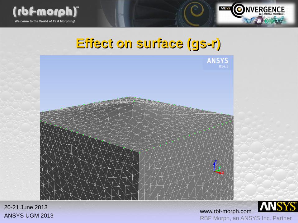
Effect on surface (gs-r)

www.rbf-morph.com
RBF Morph, an ANSYS Inc. Partner
20-21 June 2013
ANSYS UGM 2013
Effect on surface (cp-c4)

www.rbf-morph.com
RBF Morph, an ANSYS Inc. Partner
20-21 June 2013
ANSYS UGM 2013
Control of volume mesh (1166 pts)

www.rbf-morph.com
RBF Morph, an ANSYS Inc. Partner
20-21 June 2013
ANSYS UGM 2013
Morphing the volume mesh

www.rbf-morph.com
RBF Morph, an ANSYS Inc. Partner
20-21 June 2013
ANSYS UGM 2013
How it Works: the problem setup
• The problem must describe
correctly the desired changes
and must preserve exactly
the fixed part of the mesh.
• The prescription of the source
points and their
displacements fully defines the
RBF Morph problem.
• Each problem and its fit define
a mesh modifier or a shape
parameter.

www.rbf-morph.com
RBF Morph, an ANSYS Inc. Partner
20-21 June 2013
ANSYS UGM 2013
Background: accelerating the solver
• The evaluation of RBF at a point has a cost of order N
• The fit has a cost of order N3 for a direct fit (full populated matrix); this limit to ~10.000 the number of source points that can be used in a practical problem
• Using an iterative solver (with a good pre-conditioner) the fit has a cost of order N2; the number of points can be increased up to ~70.000
• Using also space partitioning to accelerate fit and evaluation the number of points can be increased up to ~300.000
• The method can be further accelerated using fast pre-conditioner building and FMM RBF evaluation…
www.rbf-morph.com
RBF Morph, an ANSYS Inc. Partner
20-21 June 2013
ANSYS UGM 2013
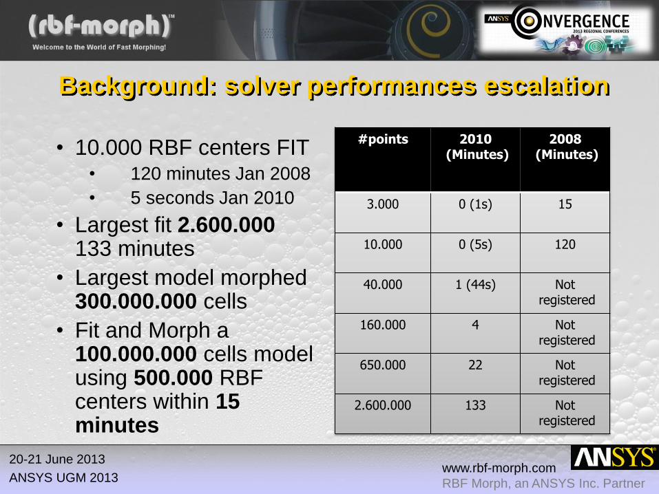
Background: solver performances escalation
• 10.000 RBF centers FIT • 120 minutes Jan 2008
• 5 seconds Jan 2010
• Largest fit 2.600.000 133 minutes
• Largest model morphed 300.000.000 cells
• Fit and Morph a 100.000.000 cells model using 500.000 RBF centers within 15 minutes
#points 2010 (Minutes)
2008 (Minutes)
3.000 0 (1s) 15
10.000 0 (5s) 120
40.000 1 (44s) Not registered
160.000 4 Not registered
650.000 22 Not registered
2.600.000 133 Not registered

www.rbf-morph.com
RBF Morph, an ANSYS Inc. Partner
20-21 June 2013
ANSYS UGM 2013
Coming soon: GPU acceleration!
• Single RBF complete evaluation
• Unit random cube
• GPU: Kepler 20 2496 CUDA Cores GPU Clock 0.71 GHz
• CPU: quad core Intel(R) Xeon(R) CPU E5-2609 0 @ 2.40GHz
#points CPU GPU speed up
5000 0,098402 0,004637 21,2
10000 0,319329 0,011746 27,2
15000 0,667639 0,024982 26,7
20000 1,135127 0,038352 29,6
25000 1,721781 0,054019 31,9
30000 2,451661 0,079459 30,9
35000 3,306897 0,108568 30,5
40000 4,286706 0,134978 31,8
45000 5,390029 0,181181 29,7
50000 6,707721 0,2135 31,4
100000 26,13633 0,745482 35,1
150000 58,96981 1,735367 34,0
200000 115,3628 2,861737 40,3
www.rbf-morph.com
RBF Morph, an ANSYS Inc. Partner
20-21 June 2013
ANSYS UGM 2013
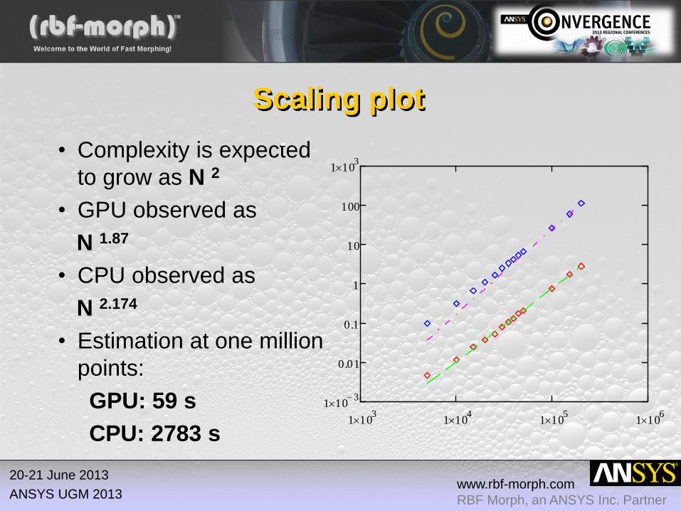
Scaling plot
• Complexity is expected
to grow as N 2
• GPU observed as
N 1.87
• CPU observed as
N 2.174
• Estimation at one million
points:
GPU: 59 s
CPU: 2783 s
1 103
1 104
1 105
1 106
1 103
0.01
0.1
1
10
100
1 103

www.rbf-morph.com
RBF Morph, an ANSYS Inc. Partner
20-21 June 2013
ANSYS UGM 2013
Industrial Applications

www.rbf-morph.com
RBF Morph, an ANSYS Inc. Partner
20-21 June 2013
ANSYS UGM 2013
Mo
torb
ike
Win
dsh
ield
(Bri
co
mo
to,
MR
A)

www.rbf-morph.com
RBF Morph, an ANSYS Inc. Partner
20-21 June 2013
ANSYS UGM 2013
Sails
Tri
m (
Ign
azio
Mari
a V
iola
,
Un
ivers
ity o
f N
ew
ca
stl
e)

www.rbf-morph.com
RBF Morph, an ANSYS Inc. Partner
20-21 June 2013
ANSYS UGM 2013
Exh
au
st
man
ifo
ld
Co
ns
tra
ine
d O
pti
miz
ati
on
Ad
join
t S
olv
er

www.rbf-morph.com
RBF Morph, an ANSYS Inc. Partner
20-21 June 2013
ANSYS UGM 2013
Optimized vs. Original - Streamlines

www.rbf-morph.com
RBF Morph, an ANSYS Inc. Partner
20-21 June 2013
ANSYS UGM 2013
Op
tim
iza
tio
n o
f sw
ee
p a
ng
les
(Pia
gg
io A
ero
In
du
str
ies)

www.rbf-morph.com
RBF Morph, an ANSYS Inc. Partner
20-21 June 2013
ANSYS UGM 2013
Op
tim
iza
tio
n o
f n
ace
lle
(D’Appolonia
)

www.rbf-morph.com
RBF Morph, an ANSYS Inc. Partner
20-21 June 2013
ANSYS UGM 2013
50
:50
:50
Pro
jec
t V
olv
o X
C60
(An
sys
, In
tel, V
olv
o)

www.rbf-morph.com
RBF Morph, an ANSYS Inc. Partner
20-21 June 2013
ANSYS UGM 2013
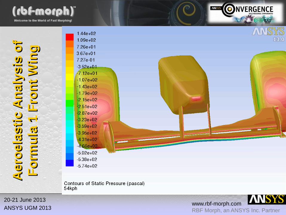
Ae
roe
las
tic A
na
lys
is o
f
Fo
rmu
la 1
Fro
nt
Win
g
Mode Disp(mm) Max err(mm) Max err (%)
1 7,19 1,61 22,39
2 7,19 0,86 12,00
3 6,98 0,85 12,15
4 6,90 0,66 9,50
5 6,85 0,19 2,76
2 Ways FSI 6,98 0,00 0,00
www.rbf-morph.com
RBF Morph, an ANSYS Inc. Partner
20-21 June 2013
ANSYS UGM 2013
Ae
roe
las
tic A
na
lys
is o
f
Fo
rmu
la 1
Fro
nt
Win
g

www.rbf-morph.com
RBF Morph, an ANSYS Inc. Partner
20-21 June 2013
ANSYS UGM 2013
What is MorphLab?
Morph lab is the convergence point of academic research, industrial innovation, software and hardware development, where people, companies
and developers can work together to push knowledge to a higher level.
Why MorphLab?
• partners can find fast solutions to specifical morph related industrial cases,
• hardware and software products can be tested and improved in demanding applications,
• product developers can advance their knowledge in the field of mesh morphing sharing data and workflows.

www.rbf-morph.com
RBF Morph, an ANSYS Inc. Partner
20-21 June 2013
ANSYS UGM 2013

www.rbf-morph.com
RBF Morph, an ANSYS Inc. Partner
20-21 June 2013
ANSYS UGM 2013
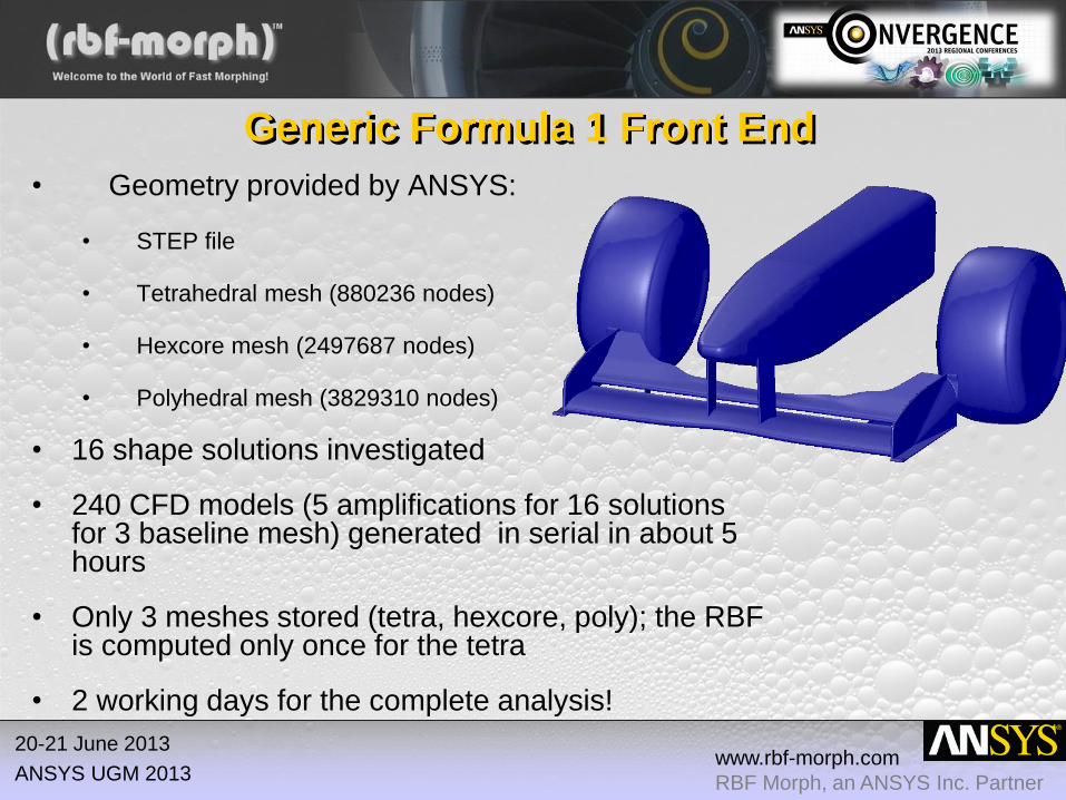
Generic Formula 1 Front End
www.rbf-morph.com
RBF Morph, an ANSYS Inc. Partner
20-21 June 2013
ANSYS UGM 2013
Generic Formula 1 Front End
• Geometry provided by ANSYS:
• STEP file
• Tetrahedral mesh (880236 nodes)
• Hexcore mesh (2497687 nodes)
• Polyhedral mesh (3829310 nodes)
• 16 shape solutions investigated
• 240 CFD models (5 amplifications for 16 solutions for 3 baseline mesh) generated in serial in about 5 hours
• Only 3 meshes stored (tetra, hexcore, poly); the RBF is computed only once for the tetra
• 2 working days for the complete analysis!

www.rbf-morph.com
RBF Morph, an ANSYS Inc. Partner
20-21 June 2013
ANSYS UGM 2013
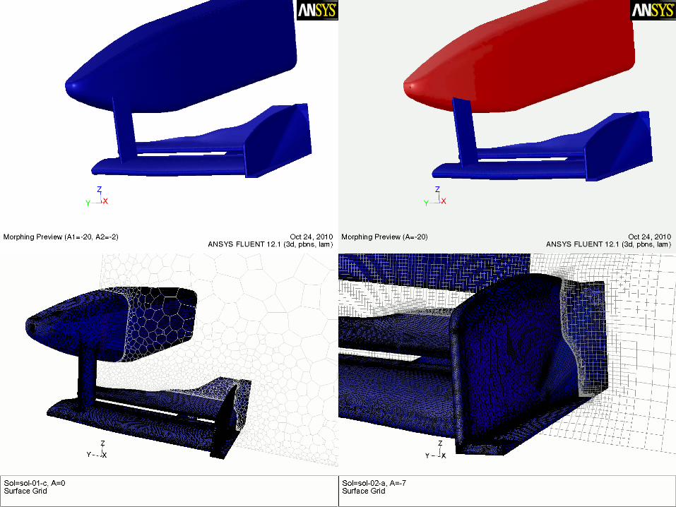
Explored modifiers
1. Spanwise extension of the whole front wing (3 variations)
2. Rotation of the end plate of the front wing (about x and z axis)
3. Rigid movements of the flap (rotation, rigid translation in x and z)
4. Translation in z and x (two variations) of the whole front wing, for the x translation include also the vertical strut
5. Rotation of the whole front wing around the y axis
6. Coupling 4 & 5
7. Bending of the nose of the body (two variations)
8. Wing vane adjust (two variations)

www.rbf-morph.com
RBF Morph, an ANSYS Inc. Partner
20-21 June 2013
ANSYS UGM 2013
Summary (tet mesh case, serial)
Solution Unit Range Solution
Time (s)
Morphing
Time (s)
Skeweness Range
(5 values equal spaced; unreformed 0,8499)
01-a mm 0:-20 1 23 0,8499 0,8569 0,8638 0,9068 0,9457
01-b mm 0:-20 1 21 0,8499 0,8499 0,8566 0,9089 0,9475
01-c mm 0:-20 1 11 0,8499 0,8499 0,8499 0,9075 0,9607
02-a deg -7:7 1 11 0,9562 0,8499 0,8499 0,8606 0,9802
02-b deg -3:3 1 11 0,9935 0,8687 0,8499 0,8499 0,9929
03-a deg -5:5 40 78 0,9957 0,9165 0,8499 0,9323 0,9840
03-b mm -10:10 32 106 0,9999 0,9720 0,8499 0,9921 0,9998
03-c mm -4:10 32 92 0,9998 0,9946 0,8499 0,9715 0,9957
04-a mm -20:30 5 45 0,8583 0,8499 0,8518 0,9306 0,9987
04-b mm -20:20 5 47 0,9043 0,8499 0,8499 0,8535 0,9434
04-c mm -20:20 5 40 0,9044 0,8601 0,8499 0,8731 0,9451
05-a mm -2.5:2.5 6 50 0,9361 0,8499 0,8499 0,8515 0,9644
07-a mm -20:20 6 48 0,8499 0,8499 0,8499 0,8499 0,8499
07-b deg -2:2 6 51 0,8635 0,8536 0,8499 0,8504 0,8532
08-a mm -5:5 8 30 0,9859 0,9258 0,8499 0,8948 0,9746
08-b mm -10:10 8 33 0,8498 0,8498 0,8499 0,8500 0,8501
www.rbf-morph.com
RBF Morph, an ANSYS Inc. Partner
20-21 June 2013
ANSYS UGM 2013

www.rbf-morph.com
RBF Morph, an ANSYS Inc. Partner
20-21 June 2013
ANSYS UGM 2013

www.rbf-morph.com
RBF Morph, an ANSYS Inc. Partner
20-21 June 2013
ANSYS UGM 2013
Importing in the CAD the
new design
• Solution 07-b with ampli = 1 has to be
reversed (nose rotation 1 deg)
• STEP file of original shape is loaded (points
overlap within Fluent GUI)
• Morphed STEP file is generated

www.rbf-morph.com
RBF Morph, an ANSYS Inc. Partner
20-21 June 2013
ANSYS UGM 2013
Conclusions
• A shape parametric CFD model can be defined using ANSYS
Fluent and RBF Morph.
• Such parametric CFD model can be easily coupled with
preferred optimization tools to steer the solution to an optimal
design that can be imported in the preferred CAD platform
(using STEP)
• Proposed approach dramatically reduces the man time required
for set-up widening the CFD calculation capability
• M.E. Biancolini, Mesh morphing and smoothing by means of
Radial Basis Functions (RBF): a practical example using Fluent
and RBF Morph in Handbook of Research on Computational
Science and Engineering: Theory and Practice (http://www.cse-
book.com/).

www.rbf-morph.com
RBF Morph, an ANSYS Inc. Partner
20-21 June 2013
ANSYS UGM 2013
RBF Morph benchmarking
for an icing application
Based on NASA Lewice 2.0 validation
results shapes
Corrado Groth
Marco Evangelos Biancolini

www.rbf-morph.com
RBF Morph, an ANSYS Inc. Partner
20-21 June 2013
ANSYS UGM 2013
Feasibility study
• The method has been implemented both in 3D and then in
2D
• MathCAD tool is used to preprocess data and generate
desired ice accretion profile (2D and 3D)
• All the tasks of this simplified workflow are conducted
using standard commands of Fluent and RBF Morph
• Points panel is used to feed the morpher with ice profile
data
• Capability of mesh morpher is validated using NASA
Lewice 2.0 validation manual shapes

www.rbf-morph.com
RBF Morph, an ANSYS Inc. Partner
20-21 June 2013
ANSYS UGM 2013
Wing profile morphing
Wing models used for the
benchmark:
• NACA0012
• GLC305
GLC305 profile was obtained
morphing the NACA0012
shape
-0,10
-0,05
0,00
0,05
0,10
0,00 0,45 0,90
Y/C
X/C
NACA0012 Clean Airfoil Profile
-0,05
0,00
0,05
0,10
0,00 0,10 0,20 0,30 0,40 0,50 0,60 0,70 0,80 0,90 1,00
Y/C
X/C
GLC305 Clean Airfoil Profile

www.rbf-morph.com
RBF Morph, an ANSYS Inc. Partner
20-21 June 2013
ANSYS UGM 2013
Wing profile morphing

www.rbf-morph.com
RBF Morph, an ANSYS Inc. Partner
20-21 June 2013
ANSYS UGM 2013
Ice accretion morphing
• All the ice shapes were taken from Nasa Lewice 2.0 validation results
manual, picking the most challenging ones.
• Ice accretion has been assumed linear, allowing for an in-flight
simulation during the ice-build up process.

www.rbf-morph.com
RBF Morph, an ANSYS Inc. Partner
20-21 June 2013
ANSYS UGM 2013
Ice accretion morphing

www.rbf-morph.com
RBF Morph, an ANSYS Inc. Partner
20-21 June 2013
ANSYS UGM 2013
Ice a
cc
reti
on
mo
rph
ing

www.rbf-morph.com
RBF Morph, an ANSYS Inc. Partner
20-21 June 2013
ANSYS UGM 2013
Ice accretion morphing

www.rbf-morph.com
RBF Morph, an ANSYS Inc. Partner
20-21 June 2013
ANSYS UGM 2013
Ice accretion morphing

www.rbf-morph.com
RBF Morph, an ANSYS Inc. Partner
20-21 June 2013
ANSYS UGM 2013
3D accretion morphing
Also for the 3D accretion
benchmark the GLC 305 clean
wing was obtained morphing the
NACA0012 profile.
3D accretion was tested
simulating both an even and a
variable profile along the span
Accretion was assumed linear in
the 3D case too.

www.rbf-morph.com
RBF Morph, an ANSYS Inc. Partner
20-21 June 2013
ANSYS UGM 2013
3D accretion morphing

www.rbf-morph.com
RBF Morph, an ANSYS Inc. Partner
20-21 June 2013
ANSYS UGM 2013
3D accretion morphing

www.rbf-morph.com
RBF Morph, an ANSYS Inc. Partner
20-21 June 2013
ANSYS UGM 2013
3D accretion morphing

www.rbf-morph.com
RBF Morph, an ANSYS Inc. Partner
20-21 June 2013
ANSYS UGM 2013
3D accretion morphing

www.rbf-morph.com
RBF Morph, an ANSYS Inc. Partner
20-21 June 2013
ANSYS UGM 2013
3D accretion morphing
Variable accretion along the span was achieved imposing two different ice shapes
at the wing extremities.
For a generic node C at span S the displacement was imposed as
C = A·(S) + B·(1-S)
Where A and B are the displacements of homologous nodes for shapes A and B
Shape A
Span 1
Shape B
Span 0

www.rbf-morph.com
RBF Morph, an ANSYS Inc. Partner
20-21 June 2013
ANSYS UGM 2013
3D accretion morphing

www.rbf-morph.com
RBF Morph, an ANSYS Inc. Partner
20-21 June 2013
ANSYS UGM 2013
3D accretion morphing

www.rbf-morph.com
RBF Morph, an ANSYS Inc. Partner
20-21 June 2013
ANSYS UGM 2013
Conclusions
• Mesh morphing capability for ice profile representation has
been demonstrated (2D and 3D).
• Quality is very good even for most challenging shapes, y+
values is preserved after morphing.
• The workflow can be easily automated without the need of
MathCAD (using Fluent UDM + UDF)
• RBF Morph is capable to fit very large RBF in a reasonable
time (100.000 points in less than 5 minutes) so large
models can be handled using the same tools

www.rbf-morph.com
RBF Morph, an ANSYS Inc. Partner
20-21 June 2013
ANSYS UGM 2013
• Research partnership (since 2009) between Piaggio Aero Industries & University of Rome Tor Vergata addressed to the solution of the aeroelastic problem using mesh morphing.
• Investigated aircraft geometries:
1. Wind tunnel model of a Piaggio business class aircraft in complete configuration.
2. Reference model of 2nd Drag Prediction workshop : DLR-F6 with nacelle.
3. Reference geometry of Aeroelastic Prediction Workshop: HIRENASD
Fluid Structure Interaction by modal superposition

www.rbf-morph.com
RBF Morph, an ANSYS Inc. Partner
20-21 June 2013
ANSYS UGM 2013
• Modal basis is computed using FEM solver
• Modes are imported into CFD model using RBF Morph
• Modal basis is validated using as reference FEM results with mapped CFD pressure
• CFD Model + Modal Basis = Flexible CFD Model
Proposed workflow

www.rbf-morph.com
RBF Morph, an ANSYS Inc. Partner
20-21 June 2013
ANSYS UGM 2013
• CFD Model + Modal Basis = Flexible CFD Model • Flexible CFD model allows to do a steady aeroelastic run at the
same cost of a rigid one
• Flexible CFD model can be used for transient FSI
• Actual modal coordinates can be linked to FEM for stress recovery
Proposed workflow

www.rbf-morph.com
RBF Morph, an ANSYS Inc. Partner
20-21 June 2013
ANSYS UGM 2013
• Radial Basis Function Mesh Morphing provides excellent quality of morphed meshes.
• Fast solver of RBF Morph allows to deal with very large problems even for FSI
• Modal Forces are integrated within Fluent over the CFD surface mesh with actual pressure data
• FSI commands to fast update the mesh using current modal coordinates (steady & transient)
Key RBF Morph features for modal FSI

www.rbf-morph.com
RBF Morph, an ANSYS Inc. Partner
20-21 June 2013
ANSYS UGM 2013
• Before trust the modal results the basis has to be validated with respect to full coupling and/or mapping (mm)
Modal basis validation
Mode F1 Front
Wing DLR-F6 HIRENASD Piaggio
1 7,19 4,97 15,259 4,657
2 7,19 4,797 14,183 4,412
3 6,98 4,75 14,184 4,423
4 6,90 4,76 14,257 4,448
5 6,85 4,79 14,257 4,399
6 * 4,81 14,257 4,431
Mapping 6,87 4,81 14,444 4,596
www.rbf-morph.com
RBF Morph, an ANSYS Inc. Partner
20-21 June 2013
ANSYS UGM 2013
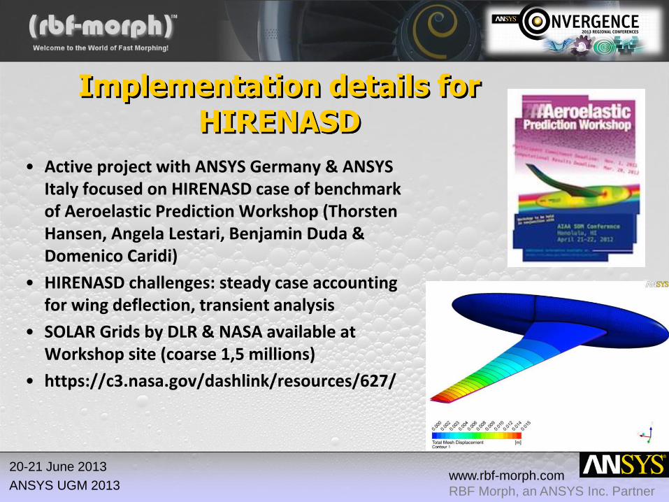
• Active project with ANSYS Germany & ANSYS Italy focused on HIRENASD case of benchmark of Aeroelastic Prediction Workshop (Thorsten Hansen, Angela Lestari, Benjamin Duda & Domenico Caridi)
• HIRENASD challenges: steady case accounting for wing deflection, transient analysis
• SOLAR Grids by DLR & NASA available at Workshop site (coarse 1,5 millions)
• https://c3.nasa.gov/dashlink/resources/627/
Implementation details for HIRENASD

www.rbf-morph.com
RBF Morph, an ANSYS Inc. Partner
20-21 June 2013
ANSYS UGM 2013
• A specific python command is defined to export FEM solutions from ANSYS Mechanical to RBF Morph
• 6 modes and static analysis results are linked
• RBF Morph set-up
• Modal basis is validated within Fluent thanks to Preview panel
• Update command defined using a scheme function and invoked each 25 iterations as a Fluent calculation activity
Set-up of FSI run

www.rbf-morph.com
RBF Morph, an ANSYS Inc. Partner
20-21 June 2013
ANSYS UGM 2013
Results: convergence history
RIGID FSI

www.rbf-morph.com
RBF Morph, an ANSYS Inc. Partner
20-21 June 2013
ANSYS UGM 2013
Results: modal coordinates and forces evolution (updated each 25 its)

www.rbf-morph.com
RBF Morph, an ANSYS Inc. Partner
20-21 June 2013
ANSYS UGM 2013
Results: rigid vs. flexible
• Trailing edge tip position is monitored at deformed and original position
• Rigid results (@ 780) and flexible results (converged @ 876) demonstrate a strong effect on Cd Cl and Cm
• Comparison with experiments will be completed after the completion of run on fine mesh (ongoing activity)

www.rbf-morph.com
RBF Morph, an ANSYS Inc. Partner
20-21 June 2013
ANSYS UGM 2013
• FSI modal approach powered by RBF mesh morphing is now an “out of the box” feature of ANSYS Fluent.
• High performances of RBF Morph allows to implement modal FSI with a minimum overhead (process calculation similar to rigid run)
• Overall procedure is reliable and validated with many industrial application (aircraft wings, F1 wings, turbo machine blades, …)
• Several ongoing activities to investigate transient effects (acceleration of 2nd mode HIRENASD, flapping wings, vibration of probes)
• Modes enforcing as a tool for strength analysis (static & transient)
Conclusions

www.rbf-morph.com
RBF Morph, an ANSYS Inc. Partner
20-21 June 2013
ANSYS UGM 2013
Thank you for your attention!
Dr. Marco Evangelos Biancolini
E-mail: [email protected]
Web: www.rbf-morph.com
YouTube: www.youtube.com/user/RbfMorph