Embed Size (px)
Citation preview

Read all instructions before operating the range hood.
Model number :
Serial Number :
PR-6830AS / PR-6836AS
XP022577(1)


IMPORTANT SAFETY NOTICE
READ AND SAVE THESE INSTRUCTIONS
a) Use this unit only in the manner intended by the manufacturer, if you have questions, contact the manufacturer. b) Before servicing or cleaning unit, switch power off at service panel and lock the service disconnecting means to prevent power from being switched on accidentally. When the service disconnecting means cannot be locked, securely fasten a prominent warning device, such as a tag, to the service panel.
a) Never leave surface units unattended at high settings. Boil overs cause smoking and greasy spillovers that may ignite. Heat oils slowly on low or medium settings. b) Always turn hood ON when cooking at high heat or when flaming food.(i.e.Cherries Jubilee, Peppercom Beef Flambe’).c) Clean ventilating fans frequently. Grease should not be allowed to accumulate on fan or filter.d) Use proper pan size. Always use cookware appropriate for the size of the surface element.e) Keep fan, fillters and grease laden surfaces clean.f ) Use high setting on hood only when necessary. g) Don’t leave hood unattended when cooking.h) Always use cookware and utensils appropriate for the type of and amount of food being prepared.
a) SMOTHER FLAMES with a close-fitting lid, cookie sheet, or metal tray, then turn off the burner. BE CAREFUL TO PREVENT BURNS. If the flames do not go out immediately, EVACUATE AND CALL THE FIRE DEPARTMENT.b) NEVER PICK UP A FLAMING PAN – You may be burned.c) DO NOT USE WATER, including wet dishcloths or towels – a violent steam explosion will result.d) Use an extinguisher ONLY if: 1) You know you have a Class ABC extinguisher, and you already know how to operate it. 2) The fire is small and contained in the area where it started. 3) The fire department is being called. 4) You can fight the fire with your back to an exit
WARNING
WARNINGTO REDUCE THE RISK OF FIRE, ELECTRIC SHOCK, OR INJURY TO PERSONS, OBSERVE THE FOLLOWING:
WARNING -TO REDUCE THE RISK OF A RANGE TOP GREASE FIRE:
WARNING -TO REDUCE THE RISK OF INJURY TO PERSONS IN THE EVENT OF A RANGE TOP FIRE, OBSERVE THE FOLLOWING:
WARNING -TO REDUCE THE RISK OF FIRE, ELECTRIC SHOCK OR INJURY TO PERSONS, OBSERVE THE FOLLOWING:
CAUTIONFor General Ventilating Use Only. Do Not Use To Exhaust Hazardous Or Explosive Materials And Vapors.
TO REDUCE THE RISK OF FIRE OR ELECTRIC SHOCK, DO NOT USE THIS FAN WITH ANY SOLID-STATE CONTROL DEVICE.
IMPORTANT SAFETY NOTICE
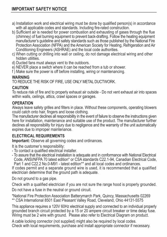
a) Installation work and electrical wiring must be done by qualified person(s) in accordance with all applicable codes and standards. Including fire-rated construction.b) Sufficient air is needed for power combustion and exhausting of gases through the flue (chimney) of fuel burning equipment to prevent back-drafting. Follow the heating equipment manufacturer’s guideline and safety standards such as those published by the National Fire Protection Association (NFPA) and the American Society for Heating, Refrigeration and Air Conditioning Engineers (ASHRAE) and the local code authorities.c) When cutting or drilling into wall or ceiling, do not damage electrical wiring and other hidden utilities.d) Ducted fans must always vent to the outdoors.e) NEVER place a switch where it can be reached from a tub or shower.f ) Make sure the power is off before installing, wiring or maintenancing.WARNINGTO REDUCE THE RISK OF FIRE, USE ONLY METAL DUCTWORK.
ELECTRICAL REQUIREMENTSImportant: Observe all governing codes and ordinances.
OPERATIONAlways leave safety grilles and filters in place. Without these components, operating blowers could catch onto hair, fingers and loose clothing.The manufacturer declines all responsibility in the event of failure to observe the instructions given here for installation, maintenance and suitable use of the product. The manufacturer further declines all responsibility for injury due to negligence and the warranty of the unit automatically expires due to improper maintenance.
CAUTIONTo reduce risk of fire and to properly exhaust air outside - Do not vent exhaust air into spaceswithin walls, ceilings, attics, crawl spaces or garages.
It is the customer’s responsibility:- To contact a qualified electrical installer.- To assure that the electrical installation is adequate and in conformance with National Electrical Code, ANSI/NFPA 70 latest edition* or CSA standards C22.1-94, Canadian Electrical Code, Part 1 and C22.2 No.0-M91 - latest edition** and all local codes and ordinances.If codes permit and a separate ground wire is used, it is recommended that a qualified electrician determine that the ground path is adequate.
*National Fire Protection Association Batterymarch Park, Quincy, Massachusetts 02269** CSA International 8501 East Pleasant Valley Road, Cleveland, Ohio 44131-5575This appliance requires a 120V 60Hz electrical supply and connected to an individual properlygrounded branch circuit protected by a 15 or 20 ampere circuit breaker or time delay fuse. Wiring must be 2 wire with ground. Please also refer to Electrical Diagram on product.A cable locking connector (not supplied) might also be required by local codes. Check with local requirements, purchase and install appropriate connector if necessary.
Do not have a fuse in the neutral or ground circuit.Check with a qualified electrician if you are not sure the range hood is properly grounded.Do not ground to a gas pipe.

Table of Content
I. Product Functions/Performance Specification Chart .......... 1
II. Parts Supplied .................................................................. 2
III. Installation Guidelines ........................................................ 3
IV. Installation Procedures ....................................................... 4
V. Operating Instructions ........................................................ 5
VI. Surface Maintenance ......................................................... 6
VII. Remarks ............................................................................ 7
VIII. Troubleshooting ................................................................ 8

I. Product Functions/Performance Specification Chart
A. Product Functions1. Delay off Button.2. One touch On/Off Button.3. Micro-Computer Programmed functions.4. Push Button: Power, Low Fan Speed, High Fan Speed, Delay-off, Light.
B. Specification Chart
C. Circuit Diagram
Net Weight(lbs)
Models
Measurement(inches)
Maximum Voltage
Exhaust Pipe Diameter
LightMaximum Operating Current
PR-6830AS
2A
120 V – 60 Hz
6 inches
LED light 6W x 2
PR-6836AS
1.
YELLOW
BLUE
WHITE
YELLOW
Motor1
WHITE
BLUE
Motor2
AC120V
BODY
GREEN
WHITE
BLACK
BLUE
FUSE 8A 250VAC
CONTROL PCB
WHITE
BLACK
BLACK
BLACK
WHITE
BROWN
BLACK
BROWN
BROWN
WHITE
LED LED
CIRCUIT DIAGRAM
34 37
(W)29-3/4 x(D)6-1/2 x(H)20-1/2 (W)35-11/16 x(D)6-1/2 x(H)20-1/2

2.
II. Parts Supplied
(1) Hardware Packet
(1) Oil Cup
(1) Bottom panel
(1) Switch assembly
(1) LED light
(1) Hood body
HARDWARE PACKAGE CONTENTS (For USA)
3
4
6
6
A
C
B
D
2
2F
E
G3/16 x 1/2" screws
3/16 x 1/4" screws
Wall Bracket
C
P3 Wire nuts
5 x 12 x 1T Washers
DESCRIPTION Q’ty
HARDWARE PACKAGE CONTENTS (For Canada)
TYPE DESCRIPTION Q’tyTYPE
DESCRIPTION Q’tyTYPE DESCRIPTION Q’tyTYPE
P3 Wire nuts
5 x 12 x 1T Washers
3
4
A
B
#6 x 1-1/2" Wood screws
#6 x 1-1/2" Wood screws
2
2
D
E
4
3/16 x 1/4" screws 2
Round Rubber Stand
Round Rubber Stand
(1) Collar
(1) Housing
(1) Bottom Filters

3.
III. Installation Guidelines
Check the surrounding of range hood. If thereare too many windows or doors nearby, it is advisable to close the windows and doors before turning on the range hood to prevent the external convection and affecting the ventilation. The smoke has to rise up to 10 inches from the stove/grate to be within the range of venting efficiency.
The ideal installation height is a distance of 24 to 30 inches from the bottom of the range hood to the surface of the stove top.
The front, back, right and left of hood must bein parallel and horizontal level, to avoid the oilin the oil tub from spilling over. To ensure that the hood is leveled when installing, it can be measured by the hook mark for the left and right side; and the screws fixed securely onto the wall to ensure the front and back of the hood are parallel.
In order to increase the venting efficiency of the hood, it is recommended to use the 6 inches duct to maintain the best air flow efficiency; the length of ductmust also be as minimal as possible.
Please do not plug the range hood to the circuit breaker with other high electricity consumption appliances.
Before installing the hood, please apply fast drying glue to the collar and securely attach it to the top of the range hood’s vent lid. Install the range hood and attach pipe to the plastic collar and seal with aluminum tape and prevent steam and smoke leakage.
Too many windows, too much convectionFig. 1
Fig. 2
Fig. 3
1. Surrounding Environment (Fig.1)
2. Installation Heights (Fig.2)
3. Hood installed in parallel and horizontal level (Fig.3)
4. Exhaust duct
5. Electrical arrangement
24~30 in

4.
IV. Installation Procedures
Duct covermountingbracket
1. Prepare duct location on hood (vertical). 2. Measure and cut out duct and electrical openings in cabinet or wall to match up with the hood. Ducting and electrical dimensions can be found on Page 1. Note: Makesure duct opening is large enough to apply aluminum duct tape. 3. Reinforce cabinet bottom with wood strips if additional strengthening is required or if cabinets are framed. 4. Remove bottom panel from hood using a Philips head screwdriver to remove each of the (5) screws.
6. Install (4) wood screws to cabinet bottom
5. Stick the two round rubber stands on the sides of hood’s top. (see Fig 2)
These screwswill be used to secure the hood to the cabinet. 7. Lift hood onto screws located on cabinet bottom and lock into place. Make sure all (4)key-holes cover the screws. Tighten each screw to secure hood to cabinet. 8. Install electrical. 9. Install duct work and seal with aluminum duct tape.
10. Power up hood and check for leaks around duct tape and test all functions.11. Reinstall bottom panel and re-connect lighting harness.12. Install oil cups into their openings on the bottom of the hood and re-install the stainless baffle filters into the hood.
wood blocking
installation screwsand key-holes
duct work
electrical
e p a t t c u d
Fig 1
Fig 2
bottom panel
oil cup
baffle filter
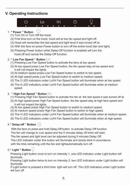
V. Operating Instructions
(1) Pressing Low Fan Speed button to activate the fans at low speed.(2) At low speed press Low Fan Speed button, the fan speed stay at low speed and it will not impact the lights.
(4) At high speed press Low Fan Speed button to switch to medium speed.(3) At medium speed press Low Fan Speed button to switch to low speed.
(5) The 2 LED indicators under Lo/Hi Fan Speed button will illuminate when at low speed.(6) The 4 LED indicators under Lo/Hi Fan Speed button will illuminate when at medium speed.
(5) The 4 LED indicators under Lo/Hi Fan Speed button will illuminate when at medium speed.(6) The 6 LED indicators under Lo/Hi Fan Speed button will illuminate when at high speed.
(1) Pressing High Fan Speed button to activate the fan at the last speed it was turned off at.(2) At high speed press High Fan Speed button, the fan speed stay at high fans speed and it will not impact the lights.(3) At low speed press High Fan Speed button to switch to medium speed.(4) At medium speed press High Fan Speed button to switch to high speed.
(1) Turn On or Turn Off the hood.(2) First time turn on the hood, hood will at low fan speed and light off.(3) Hood will remember the last speed and light level it was turned off at.(4) With the fans on press Power button to turn off the entire hood (fan and light).
With the fans on press and hold Delay-Off button to activate Delay Off function. The fan will change to Low speed and the 5 minutes delay off timer will start. The fan speed and light level can be adjusted during 5 minutes Delay Off. The LED indicator under this button will illuminate and slowly blink in accordance with the time remaining until the fan and lightautomatically turn off.
(5) Pressing Power button while Delay-Off function is enabled will turn the hood off and cancel the Delay-Off function.
1. “ Power ” Button
2. “ Low Fan Speed ” Button
3. “ High Fan Speed ” Button
Pressing Light button once to turn on intensity 1, one LED indicator under Light button will illuminate.Pressing Light button twice to turn on intensity 2, two LED indicators under Light button will illuminate.If Light button is pressed a third time, light will turn off. The LED indicators under Light button will turn off.
5.“ Light ” Button
5.
4.“ Delay-off ” Button

6.
VI. Surface MaintenanceA. Surface Maintenance
1. Please clean the range hood surface regularly with warm soapy water and wipe with a cotton cloth to prevent grease from accumulating.2. Please do not use harsh cleansers or coarse material to clean the surface because that will damage the surface.3. A non-invasive stainless steel polish is recommended to polish the surface after cleaning.4. Please use soft cloth for polishing because it will make your range hood surface shinier.5. Please do not use cleaning solutions that have bleach as an ingredient.
B. Surface Cleaning and Maintenance
1. Always disconnect from power supply before cleaning.2. Clean both exterior and interior of the hood for long lasting. Do not use abrasive cleanser.3.The stainless steel baffle fi lters are intended to trap residue and grease from cooking. Although the filters should never need replacing, they are required to be cleaned every 30 days or more often depending on cooking habits. Filters may be placed in dishwasher at low heat or soaked in hot soapy water Dry filters and re-install before using hood.4. The oil cup in the center of the hood for holding grease can be detached and cleaned regularly.5. Make a habit of turning on the range hood first before turning on the stove to avoid high temperature in the kitchen.

7.
VII. Remarks
1. When filling the range hood with the cleaner mixture, use only the special jar provided with the range hood and take precautions not to overfill the cleaner storage unit.2. Check the oil retainer during the cleaning process to prevent oil spillage. Do not allow dirty oil to exceed the marked level.3. Do not put any other substances into the cleaner compartment unit as this will cause blockage of its injection hole.4. The cleaner storing unit and the supplied jar are of identical size. The cleaner mixture stored can be used for 5 to 6 times. The cleaner storage unit may be refilled by diluted cleaner mixture every time after use. To prevent overfilling,5. Always turn the range hood on first before turning the cooktop on as high heat may damage the range hood.6. If the supply cord is damaged, it must be replaced by the manufacturer or its service agent or a similar qualified person in order to avoid a hazard.
A. Precautions:

8.
VIII. Troubleshooting
Problem
Motor stopsrunning
Possible Cause Solution1. No power (burnedwire or fuse) 1. Replace the PC board
3. Motor copper wire is burned 3. Replace motor
4. Capacitor defected 4. Replace capacitor
1. Distorted capacitor or low power 1. Replace capacitor
1. Short circuit on the motor 1. Replace motor
2. Motor defected 2. Replace motor
2. Replace motor
1. Capacitor defected 1. Replace capacitor
1. Recommend changing your cooking routine slightly
2. Electrical wiring is off 2. Fix the electrical wires
1. Main control PC board failed
2. PC board switch failed
2. PC board switch failed
2. PC board failed switch
1. Short circuit on LED light control power cord
1. Replace main control PC board
1. Water got in the motor 1. Replace motor
1. Main control PC board failed 1. Replace main control PC board
2. Short circuit on the light power cord in the main control PC board
2. Replace main control PC board
2. Replace PC board switch
5. No power (burned wire) or burned fuse 5. Check power meter (replace power cord)
2. Air comes out of the air outlet instead of sucks up
1. Motor stops running when it reaches unusual high temperature, and starts again when it cools down to normal cooking temperature. This is cause by temperature running too high during cooking.
2. Air outlet or exhaust pipe is blocked and needs cleaning
1. Raplace LED light control power cord
3. LED light failed 3. Replace LED light
2. Motor temperature regulator is off and can’t be recovered
2. Replace motor
Motor speedslows downautomatically
Inverted fanblades
Motor doesn’tregulate speed
Motor runs onand off
Delay-offfunction fails
Power leakage
Display unitfailed
LED light notworking
8.
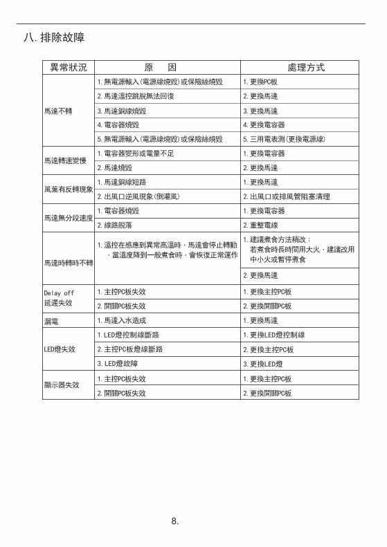
八.排除故障
異常狀況
馬達不轉
原 因 處理方式
馬達轉速變慢
風葉有反轉現象
馬達無分段速度
馬達時轉時不轉
1.無電源輸入(電源線燒毀)或保險絲燒毀
2.馬達溫控跳脫無法回復
3.馬達銅線燒毀
4.電容器燒毀
5.無電源輸入(電源線燒毀)或保險絲燒毀
1.電容器變形或電量不足
2.馬達燒毀
1.馬達銅線短路
2.出風口逆風現象(倒灌風)
1.電容器燒毀
2.線路脫落
1.更換PC板
2.更換馬達
3.更換馬達
2.更換馬達
2.更換馬達
1.更換馬達
2.出風口或排風管阻塞清理
4.更換電容器
1.更換電容器
2.重整電線
1.更換電容器
1.主控PC板失效
2.開關PC板失效 2.更換開關PC板
1.更換主控PC板
1.主控PC板失效
2.開關PC板失效 2.更換開關PC板
1.更換主控PC板
1.馬達入水造成 1.更換馬達
1.LED燈控制線斷路
2.主控PC板燈線斷路
3.LED燈故障 3.更換LED燈
2.更換主控PC板
1.更換LED燈控制線
1.溫控在感應到異常高溫時,馬達會停止轉動
,當溫度降到一般煮食時,會恢復正常運作
1.建議煮食方法稍改:
若煮食時長時間用大火,建議改用
中小火或暫停煮食
5.三用電表測(更換電源線)
Delay off
延遲失效
漏電
顯示器失效
LED燈失效

7.
七.注意事項及警告標示
一.注意事項及警告標示:
1.每次煮食前先開啟抽油煙機,在開始煮食,可防止高溫損壞排油煙機。
2.假若電源線損壞時,必須經由製造廠商或服務站或是類似專業的人員更換,
避免造成危險。

6.
六.機身表面保養和清潔
一.機身表面保養
1.請定期以熱肥皂水和棉布擦拭機身以防油垢堆積。
2.請勿使用腐蝕性洗碗精和材質過粗的布料擦拭,以免傷害到機身表面。
3.擦拭完成後建議使用無刺激性的不鏽鋼拋光劑來進行第二次擦拭。
4.請使用軟布輕擦,您的油煙機表面將會更加光亮。
5.請勿使用含有漂白成分的清潔液。
二.保養和清潔
1.清潔前,務必要切斷電源。
2.定期清潔抽油煙機的內外側,可以保持抽油煙機壽命,
切勿使用研磨性清潔劑。
3.請將不鏽鋼濾網從煙罩取下,濾網可過濾煮食中的油 脂及殘留物。儘管濾網不需要更換,但建議根據煮食 習慣至少每30天清潔一次。 請將濾網置於洗碗機中低溫清洗或浸泡於熱肥皂水中 清洗,待濾網乾燥後重新安裝於煙罩上。
4.將油杯由油槽下方取下並做清潔。
5.在開啟煮食爐前,請先開啟抽油煙機以免廚房溫度太高。

五.按鍵說明
1.“ 電源 ”鍵
(1) 輕按按鍵開啟或關閉排油煙機。
(2) 初次啟動時,風速預設為低速,照明關閉。
(3) 再次啟動時,會自動記憶前次使用之風速及照明段數。
(4) 排油煙機開啟時,輕按此鍵關閉油煙機所有動作。
(2) 排油煙機開啟時,按此鍵可啟動五分鐘延遲關機功能,此鍵下方LED指示燈
會開始閃爍,風扇自動低速運轉、照明段數不變﹔延遲關機功能進行期間
可調整風速及照明,五分鐘後風扇及照明會自動關閉。
(5) 延遲關機啟動狀態下,輕按此鍵關閉油煙機和延遲關機功能。
2.“ 風扇低速”鍵
(1) 輕按此鍵可啟動低速風速。
(2) 風扇低速運轉時,輕按此鍵無作用維持低速運轉,不影響照明。
(4) 風扇高速運轉時,
,
輕按此鍵切換為中速。
(3) 風扇中速運轉時,輕按此鍵切換為低速。
(5) 風扇低速運轉時,按鍵下方兩個LED指示燈會亮起。
。
。
(6) 風扇中速運轉時,按鍵下方四個LED指示燈會亮起。
(6) 風扇高速運轉時,按鍵下方六個LED指示燈會亮起。
3.“ 風扇高速”鍵
(1) 輕按此鍵可啟動之前記憶高速風扇。
(2) 風扇高速運轉時,輕按此鍵無作用維持高速運轉 不影響照明
(3) 風扇低速運轉時,輕按此鍵切換為中速。
(4) 風扇中速運轉時,輕按此鍵切換為高速。
(5) 風扇中速運轉時,按鍵下方四個LED指示燈會亮起。
5.“ 照明”鍵
(1) 輕按此鍵可開啟照明依序微亮 全亮 關閉,不影響風速。
(2) 當LED照明微亮時,按鍵下方一個指示燈會亮起。
(3) 當LED照明全亮時,按鍵下方兩個指示燈會亮起。
5.
4.“ 延遲關機”鍵
(1) 輕按此鍵可啟動延遲功能。延遲功能啟動時,按鍵下方LED指示燈會閃爍﹔
再按一次延遲功能鍵無動作,需輕按(電源鍵)終止延遲功能。

4.
四.安裝步驟
1.請準備安裝位置及空間(上出風)。
2.測量出風口及電源線孔的大小,然後
再鑽孔。
備註:出風口尺寸應要足以安裝鋁
風管。
3.櫥櫃需加強本機固定的地方,建議使
用木條強化在櫥櫃內底部。
4.請用十字螺絲起子移除油機煙罩上5
6.依安裝位置設置4支木螺釘 。
5.在抽油煙機頂部兩端黏貼抬腳(如圖2)
7.安裝時用木螺釘扣上之後,將油機與
櫥櫃用螺絲鎖緊,確保油機穩固的安
裝在櫥櫃上不會掉落。
8.裝設電源。
9.安裝風管並用風管膠帶密封。
10.檢查風管處是否緊密及其他功能是否
正常。
11.將油機煙罩重新鎖上螺絲安裝於油機
下方。
12.將油杯與不鏽鋼濾網重新安裝至油機。
木條
木螺釘鑰匙孔
風管圈孔
電源線孔
風管膠帶
圖 1
圖 2
油杯
不鏽鋼濾網
煙罩
支螺絲(如圖1)並取下油機煙罩。

3.
三.安裝原則
抽油煙機安裝位置,如在窗上或附近有太多門
窗,請在開動抽油煙機前,先關閉門窗,以免
空氣對流大而影響吸力,因當油煙上昇未至10
英吋之有效吸力範圍,則無法充分發揮抽油煙
最佳效果。
1. 周圍環境(圖一):
安裝高度自本機底板至煮食爐面之距離以24~
30英吋為最理想。
2. 安裝高度(圖二):
機體應保持前、後、左、右水平,以免氣流箱,
導油盆積油而溢出。
左、右水平可由掛碼調整,前、後水平則由鋼
釘螺絲鎖緊牆壁,以固定標準。
3. 機體應保持水平(圖三):
4. 排風管:
5. 插座安排:
安裝前先以矽利康注入風管圈後將風管崁入,再用封膠封住風管圈。
為增加吸力效能,請配合使用本機出風管接頭
之直徑6英吋排風管 ,排風管長度應以適合長
度最佳,不宜過長。
請勿與烤箱或冰箱等耗電量較高之電器產品共
用一個插座。
24~30 in
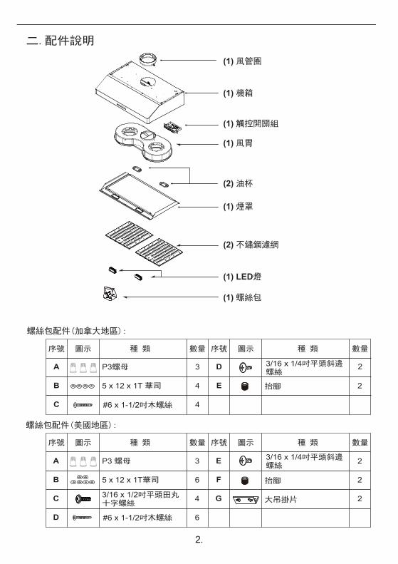
二.配件說明
2.
螺絲包配件(美國地區):
3
4
6
6
A
C
B
D
2
2
2
2
F
E
G
3/16 x 1/4吋平頭斜邊
3/16 x 1/2吋平頭田丸十字螺絲 大吊掛片
C
P3 螺母
5 x 12 x 1T華司
種 類 數量
螺絲包配件(加拿大地區):
序號
P3螺母
5 x 12 x 1T 華司
3
4
A
B
種 類 數量
#6 x 1-1/2吋木螺絲
#6 x 1-1/2吋木螺絲
2D
E
4
(1) 風管圈
(1) 風胃
(2) 不鏽鋼濾網
(1) 煙罩
(1) 螺絲包
(1) 觸控開關組
(1) LED燈
(2) 油杯
(1) 機箱
圖示 序號 圖示
種 類 數量序號 種 類 數量圖示 序號 圖示
抬腳
抬腳
螺絲
3/16 x 1/4吋平頭斜邊螺絲
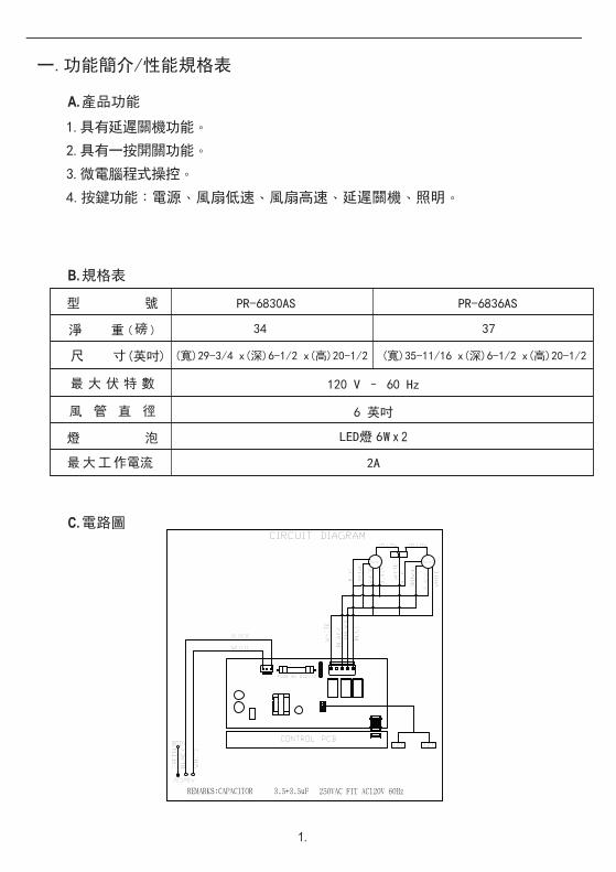
一.功能簡介/性能規格表
1.具有延遲關機功能。
2.具有一按開關功能。
3.微電腦程式操控。
4.按鍵功能:電源、風扇低速、風扇高速、延遲關機、照明。
A.產品功能
B.規格表
C.電路圖
PR-6830AS
磅 34 37淨 重 (
(英吋)
)
型 號
尺 寸
最 大 伏 特 數
風 管 直 徑
燈 泡
最大工作電流
1.
PR-6836AS
120 V – 60 Hz
6 英吋
2A
LED燈 6W x 2
YELLOW
BLUE
WHITE
YELLOW
Motor1
WHITE
BLUE
Motor2
AC120V
BODY
GREEN
WHITE
BLACK
BLUE
FUSE 8A 250VAC
CONTROL PCB
WHITE
BLACK
BLACK
BLACK
WHITE
BROWN
BLACK
BROWN
BROWN
WHITE
LED LED
CIRCUIT DIAGRAM
(寬)29-3/4 x(深)6-1/2 x(高)20-1/2 (寬)35-11/16 x(深)6-1/2 x(高)20-1/2

目錄
一.功能簡介/性能規格表 ................................ 1
二.配件說明 ................................................. 2
三.安裝原則 ................................................. 3
四.安裝步驟 ................................................. 4
五.按鍵說明 ................................................. 5
六.機身表面保養和清潔 ...................................6
七.注意事項 ................................................. 7
八.排除故障 ................................................. 8


(使用前,請先詳細閱讀此說明書 )
抽 油 煙 機
使 用 說 明 書
抽 油 煙 機
使 用 說 明 書
抽油機型號: PR-6830AS / PR-6836AS
序 號:
XP022577(1)