Embed Size (px)
Citation preview
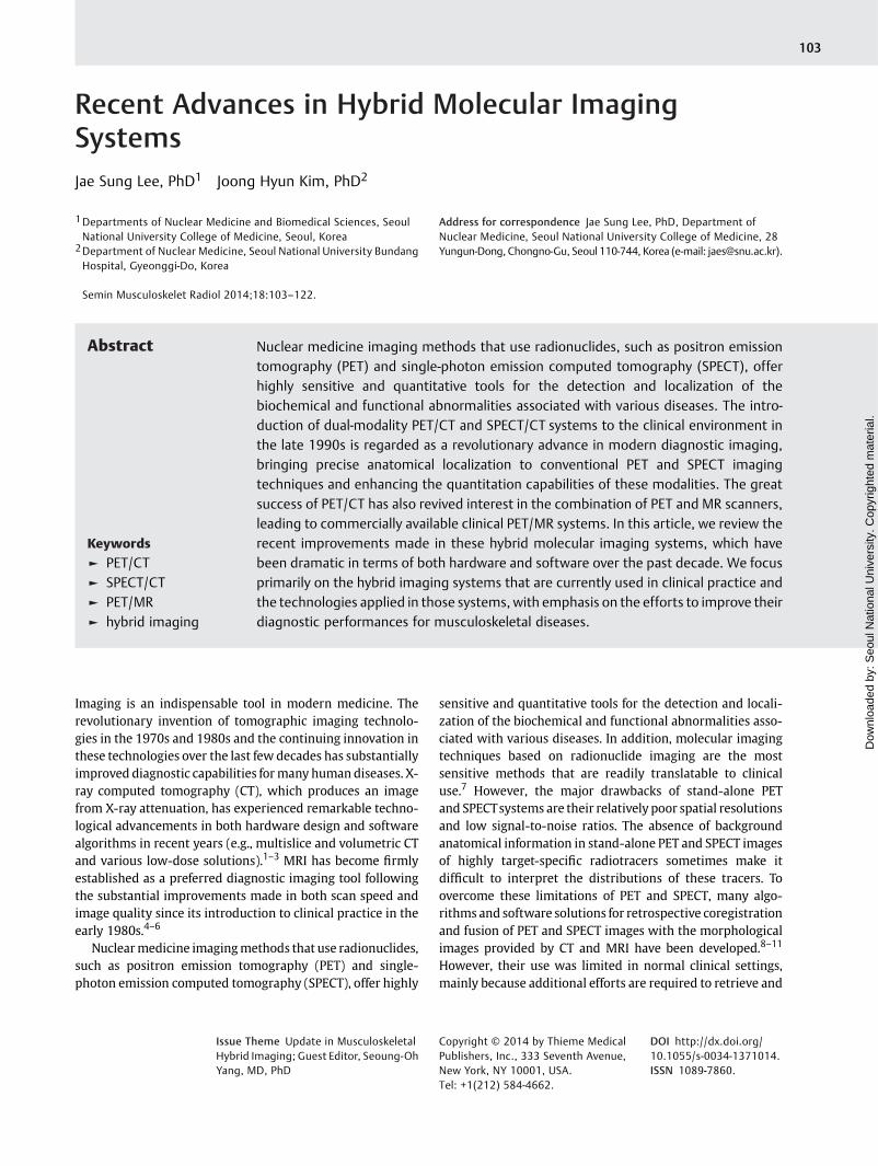
Recent Advances in Hybrid Molecular ImagingSystemsJae Sung Lee, PhD1 Joong Hyun Kim, PhD2
1Departments of Nuclear Medicine and Biomedical Sciences, SeoulNational University College of Medicine, Seoul, Korea
2Department of Nuclear Medicine, Seoul National University BundangHospital, Gyeonggi-Do, Korea
Semin Musculoskelet Radiol 2014;18:103–122.
Address for correspondence Jae Sung Lee, PhD, Department ofNuclear Medicine, Seoul National University College of Medicine, 28Yungun-Dong, Chongno-Gu, Seoul 110-744, Korea (e-mail: [email protected]).
Imaging is an indispensable tool in modern medicine. Therevolutionary invention of tomographic imaging technolo-gies in the 1970s and 1980s and the continuing innovation inthese technologies over the last few decades has substantiallyimproved diagnostic capabilities formany human diseases. X-ray computed tomography (CT), which produces an imagefrom X-ray attenuation, has experienced remarkable techno-logical advancements in both hardware design and softwarealgorithms in recent years (e.g., multislice and volumetric CTand various low-dose solutions).1–3 MRI has become firmlyestablished as a preferred diagnostic imaging tool followingthe substantial improvements made in both scan speed andimage quality since its introduction to clinical practice in theearly 1980s.4–6
Nuclearmedicine imagingmethods that use radionuclides,such as positron emission tomography (PET) and single-photon emission computed tomography (SPECT), offer highly
sensitive and quantitative tools for the detection and locali-zation of the biochemical and functional abnormalities asso-ciated with various diseases. In addition, molecular imagingtechniques based on radionuclide imaging are the mostsensitive methods that are readily translatable to clinicaluse.7 However, the major drawbacks of stand-alone PETand SPECTsystems are their relatively poor spatial resolutionsand low signal-to-noise ratios. The absence of backgroundanatomical information in stand-alone PET and SPECT imagesof highly target-specific radiotracers sometimes make itdifficult to interpret the distributions of these tracers. Toovercome these limitations of PET and SPECT, many algo-rithms and software solutions for retrospective coregistrationand fusion of PET and SPECT images with the morphologicalimages provided by CT and MRI have been developed.8–11
However, their use was limited in normal clinical settings,mainly because additional efforts are required to retrieve and
Keywords
► PET/CT► SPECT/CT► PET/MR► hybrid imaging
Abstract Nuclear medicine imaging methods that use radionuclides, such as positron emissiontomography (PET) and single-photon emission computed tomography (SPECT), offerhighly sensitive and quantitative tools for the detection and localization of thebiochemical and functional abnormalities associated with various diseases. The intro-duction of dual-modality PET/CT and SPECT/CT systems to the clinical environment inthe late 1990s is regarded as a revolutionary advance in modern diagnostic imaging,bringing precise anatomical localization to conventional PET and SPECT imagingtechniques and enhancing the quantitation capabilities of these modalities. The greatsuccess of PET/CT has also revived interest in the combination of PET and MR scanners,leading to commercially available clinical PET/MR systems. In this article, we review therecent improvements made in these hybrid molecular imaging systems, which havebeen dramatic in terms of both hardware and software over the past decade. We focusprimarily on the hybrid imaging systems that are currently used in clinical practice andthe technologies applied in those systems, with emphasis on the efforts to improve theirdiagnostic performances for musculoskeletal diseases.
Issue Theme Update in MusculoskeletalHybrid Imaging; Guest Editor, Seoung-OhYang, MD, PhD
Copyright © 2014 by Thieme MedicalPublishers, Inc., 333 Seventh Avenue,New York, NY 10001, USA.Tel: +1(212) 584-4662.
DOI http://dx.doi.org/10.1055/s-0034-1371014.ISSN 1089-7860.
103
Dow
nloa
ded
by: S
eoul
Nat
iona
l Uni
vers
ity. C
opyr
ight
ed m
ater
ial.

process the image data and because most human organs andsoft tissues have a deformable nature that could lead to imagemismatch.
The introduction of dual-modality PET/CT and SPECT/CTsystems in the late 1990s, in which PET and SPECT arecombined with X-ray CT in a clinical setting, is regarded asa revolutionary advance in modern diagnostic imaging. Inthese systems, the PET or SPECT images are acquired sequen-tially with the CT images using a single device and withoutmoving the patient from the bed, eliminating differences inpatient positioning and minimizing the misalignmentscaused by internal organ motion.12–16 The anatomical infor-mation provided by the CT images enhances the user’sconfidence in the PET and SPECT findings. Additionally, theattenuation map derived from the X-ray CT for the gammarays emitted from the radionuclides offers useful ways tocorrect for the attenuation and scatter artifacts in PET andSPECTwith minimal addition to the scan time and the imagenoise.16–18
The concept of simultaneous acquisition of PET and MRimages was also suggested in the early days of dual-modalitysystems development, and the development of PET/MR scan-ners started in the 1990s.19,20 However, progress in thedevelopment process was relatively slow, and the realizationof clinical PET/MR scanners was greatly delayed because oftechnical difficulties when operating PET and MR scanners inclose proximity combined with a lack of industrial interestand concern over the high cost of the combined device.21 Thegreat success of nuclear medicine imaging modalities whencombined with CT has, however, revived interest in thecombination of PET and MR scanners. The technical advancesmade over the long development period to minimize themutual interferencebetween the PET andMRdata acquisitionprocesses have led to combined clinical PET/MR scannerswith sequential and simultaneous imaging strategies in re-cent years. Themajor advantages of PET/MR include a smallerradiation burden than PET/CT, better soft tissue contrastwhen using MRI rather than CT, and possible simultaneousacquisition of images.
This article reviews the recent advances in hybrid medicalimaging systems. In this review,we focusprimarilyon thehybridimaging systems that are currently available for clinical practiceand the technologies applied in those systems. In each section,thebasic principles,fields of application, and recent advances arereviewed for each hybrid imaging device. It should be noted thatmost of the technical advances in each of the components of thehybrid imaging systems are also available for the stand-alonenuclear medicine and radiologic imaging systems because theoverall performance of each hybrid imaging system is a functionof the performance of the individual components. Although theapplicationsofmostof the technologies introduced in this articleare not limited to musculoskeletal imaging, we emphasize theefforts made to improve the diagnostic performances for mus-culoskeletal diseases.
Advances in SPECT/CT
Basic Principles, Advantages, and ApplicationsSPECT has several advantages over PET, including greateraccessibility, lower cost, and better availability of radio-tracers for the investigation of a wider range of biologicalprocesses.22 Technetium 99m (99mTc) is the most widelyused radioisotope in SPECT; it has a 6-hour half-life and issimply produced using a molybdenum 99 (99Mo)/99mTcgenerator. The local production of many SPECT radiotracersis also possible using commercially available kits. Otherradioisotopes used in SPECT include gallium 67 (67Ga), indi-um 111 (111In), iodine 123 (123I), and iodine 131 (131I).Because these radioisotopes emit gamma rays with differentenergies, simultaneous data acquisition using dual or multi-ple radioisotopes is possible in principle. 99mTc-labeledphosphate-containing compounds, such as 99mTc-methyle-nediphosphonate (99mTc-MDP) and 99mTc-hydroxydi-phosphonate (99mTc-HDP), are the most widely usedradiotracers for bone imaging (►Fig. 1). In the diagnosisof musculoskeletal infection, 99mTc-dicarboxypropane di-phosphonate (99mTc-DPD), 67Ga, 111In-labeled leukocytes,and 99mTc-labeled antigranulocyte antibodies are used.23
Fig. 1 A 76-year-old female patient who experienced lower back pain underwent bone scan and SPECT/CT imaging after injection of 99mTc-MDP tofind the focus of active lesion. (a) On bone scan, a focal increased uptake was found in the left side of the L4–L5 intervertebral area. (b) On SPECT/CT, however, the focal uptake was revealed to be on the right facet joint of L4–L5. (c) In addition, a focal uptake was also found on the left facetjoint of L3–L4 that was not noticed on the bone scan.
Seminars in Musculoskeletal Radiology Vol. 18 No. 2/2014
Hybrid Molecular Imaging Systems Lee, Kim104
Dow
nloa
ded
by: S
eoul
Nat
iona
l Uni
vers
ity. C
opyr
ight
ed m
ater
ial.
Basic Principles and Design of SPECT SystemsIn SPECT imaging, single-, dual- or triple-headed gammacameras attached to a rotating gantry are used for angulardata sampling. The projection data are acquired in eitherstep-and-shoot mode or continuous mode, and they arerearranged into multiple sinograms for tomographic imagereconstruction. The gamma cameras (or SPECT detectors)consist of a collimator and a position-sensitive radiationdetector. The collimator is made from heavy radiation shield-ing material and used to reject gamma-ray photons that arenot within the desired incidence angle for each angularposition of the gamma camera. In general, there is a trade-off between resolution and sensitivity in the collimatorselection process because the collimators used for high-resolution imaging yield low sensitivities because of theirlow geometric efficiency. The radiation detector convention-ally used in gamma cameras is the scintillation detector,which indirectly converts radiation into electronic signals.In the scintillation detector used for SPECT, a large-areacontinuous NaI(Tl) scintillation crystal is coupled to an arrayof photomultipliers (PMTs) via a light guide. The visible lightphotons generated in the scintillation crystal by the gamma-ray interaction are read by the PMT array arranged in ahexagonal pattern to obtain energy and position informationfor each gamma-ray interaction.
Advances in Conventional SPECT DetectorsInmostmodern SPECT detectors based onNaI(Tl) crystals andPMTs, most of the electronics, including the front-end analogcircuit and the analog-to-digital (ADC) converters, aremounted directly on the individual PMTs to minimize signaldistortion in the long signal readout cables.24,25 These digi-tized detectors enable calculation of the gamma-ray interac-tion position and energy and the elimination of pulse pileupsin the software with more sophisticated algorithms thanthose used for conventional analog circuit-based ap-proaches.26,27 In modern gamma cameras, only PMTs with
output signals above a certain threshold are included in theposition and energy calculations. The main purposes of thissignal thresholding process are to suppress noisy signals fromthe PMTs and to allow only the output signals from the smallnumber of PMTs around the gamma-ray interaction positionto be used in the position and energy calculations. Byrestricting the number of PMTs used, the multiple eventsthat occur in different positions in a continuousNaI(Tl) crystalcan be recorded simultaneously.25,28 The modern gammacameras with these advanced hardware technologies yield� 10% full width at halfmaximum (FWHM) energy resolutionfor 99mTc and � 2- to 4-mm FWHM spatial resolution. Eventrates of up to 105 per second are typically supported.29
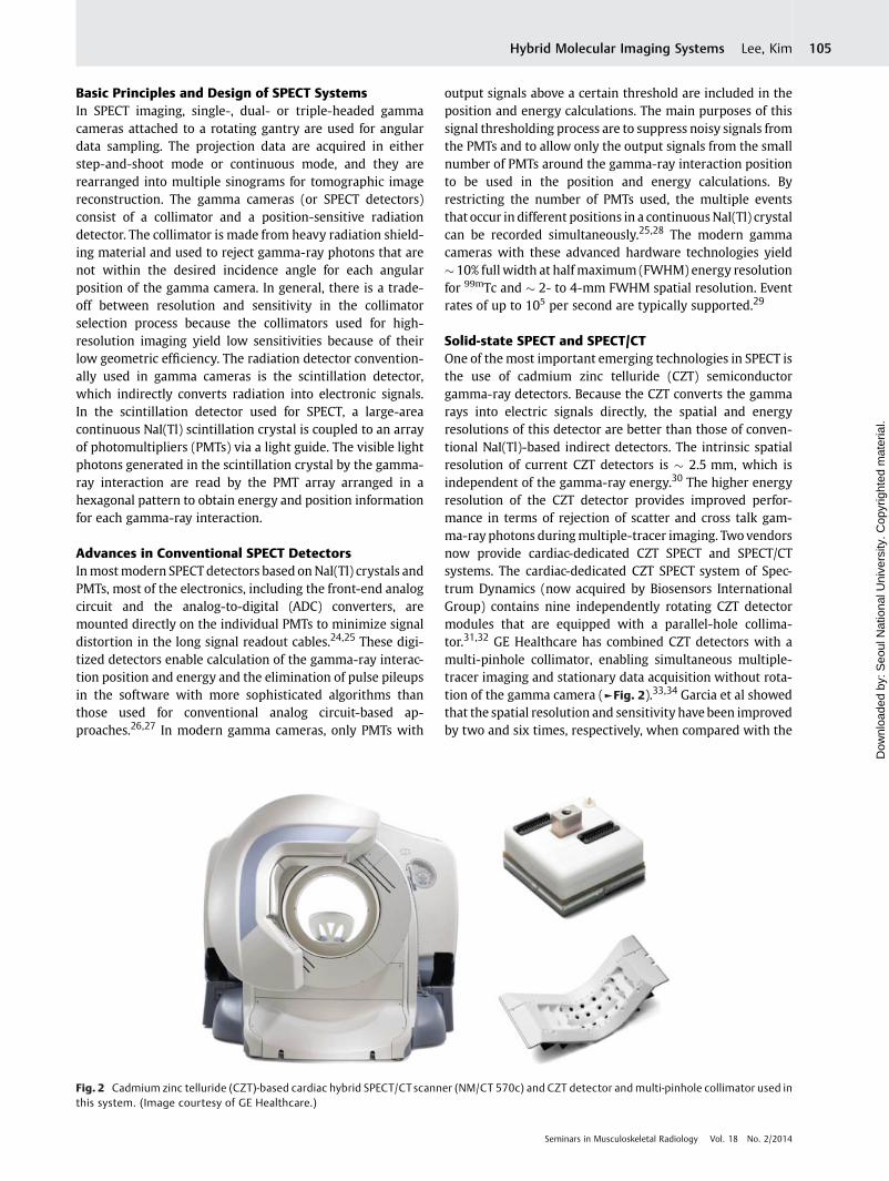
Solid-state SPECT and SPECT/CTOne of themost important emerging technologies in SPECT isthe use of cadmium zinc telluride (CZT) semiconductorgamma-ray detectors. Because the CZT converts the gammarays into electric signals directly, the spatial and energyresolutions of this detector are better than those of conven-tional NaI(Tl)-based indirect detectors. The intrinsic spatialresolution of current CZT detectors is � 2.5 mm, which isindependent of the gamma-ray energy.30 The higher energyresolution of the CZT detector provides improved perfor-mance in terms of rejection of scatter and cross talk gam-ma-ray photons duringmultiple-tracer imaging. Twovendorsnow provide cardiac-dedicated CZT SPECT and SPECT/CTsystems. The cardiac-dedicated CZT SPECT system of Spec-trum Dynamics (now acquired by Biosensors InternationalGroup) contains nine independently rotating CZT detectormodules that are equipped with a parallel-hole collima-tor.31,32 GE Healthcare has combined CZT detectors with amulti-pinhole collimator, enabling simultaneous multiple-tracer imaging and stationary data acquisition without rota-tion of the gamma camera (►Fig. 2).33,34 Garcia et al showedthat the spatial resolution and sensitivity have been improvedby two and six times, respectively, when compared with the
Fig. 2 Cadmium zinc telluride (CZT)-based cardiac hybrid SPECT/CTscanner (NM/CT 570c) and CZT detector and multi-pinhole collimator used inthis system. (Image courtesy of GE Healthcare.)
Seminars in Musculoskeletal Radiology Vol. 18 No. 2/2014
Hybrid Molecular Imaging Systems Lee, Kim 105
Dow
nloa
ded
by: S
eoul
Nat
iona
l Uni
vers
ity. C
opyr
ight
ed m
ater
ial.
properties of conventional NaI(Tl)-based cameras.35 Al-though the application of this innovative semiconductordetector technology is mainly limited to cardiac-dedicatedSPECT and SPECT/CT systems because of the cost, the com-mercial production of general-purpose scanners based onthis technology is expected in the near future.
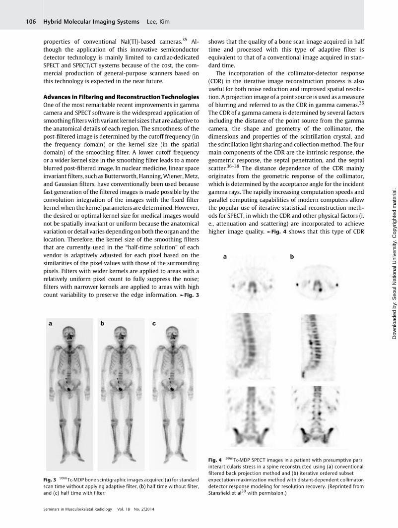
Advances in Filtering and Reconstruction TechnologiesOne of the most remarkable recent improvements in gammacamera and SPECT software is the widespread application ofsmoothingfilterswithvariant kernel sizes that are adaptive tothe anatomical details of each region. The smoothness of thepost-filtered image is determined by the cutoff frequency (inthe frequency domain) or the kernel size (in the spatialdomain) of the smoothing filter. A lower cutoff frequencyor a wider kernel size in the smoothing filter leads to a moreblurred post-filtered image. In nuclear medicine, linear spaceinvariant filters, such as Butterworth, Hanning,Wiener, Metz,and Gaussian filters, have conventionally been used becausefast generation of the filtered images is made possible by theconvolution integration of the images with the fixed filterkernelwhen the kernel parameters are determined. However,the desired or optimal kernel size for medical images wouldnot be spatially invariant or uniform because the anatomicalvariation or detail varies depending on both the organ and thelocation. Therefore, the kernel size of the smoothing filtersthat are currently used in the “half-time solution” of eachvendor is adaptively adjusted for each pixel based on thesimilarities of the pixel values with those of the surroundingpixels. Filters with wider kernels are applied to areas with arelatively uniform pixel count to fully suppress the noise;filters with narrower kernels are applied to areas with highcount variability to preserve the edge information. ►Fig. 3
shows that the quality of a bone scan image acquired in halftime and processed with this type of adaptive filter isequivalent to that of a conventional image acquired in stan-dard time.
The incorporation of the collimator-detector response(CDR) in the iterative image reconstruction process is alsouseful for both noise reduction and improved spatial resolu-tion. A projection image of a point source is used as ameasureof blurring and referred to as the CDR in gamma cameras.36
The CDR of a gamma camera is determined by several factorsincluding the distance of the point source from the gammacamera, the shape and geometry of the collimator, thedimensions and properties of the scintillation crystal, andthe scintillation light sharing and collection method. The fourmain components of the CDR are the intrinsic response, thegeometric response, the septal penetration, and the septalscatter.36–38 The distance dependence of the CDR mainlyoriginates from the geometric response of the collimator,which is determined by the acceptance angle for the incidentgamma rays. The rapidly increasing computation speeds andparallel computing capabilities of modern computers allowthe popular use of iterative statistical reconstruction meth-ods for SPECT, in which the CDR and other physical factors (i.e., attenuation and scattering) are incorporated to achievehigher image quality. ►Fig. 4 shows that this type of CDR
Fig. 3 99mTc-MDP bone scintigraphic images acquired (a) for standardscan time without applying adaptive filter, (b) half time without filter,and (c) half time with filter.
Fig. 4 99mTc-MDP SPECT images in a patient with presumptive parsinterarticularis stress in a spine reconstructed using (a) conventionalfiltered back projection method and (b) iterative ordered subsetexpectation maximization method with distant-dependent collimator-detector response modeling for resolution recovery. (Reprinted fromStansfield et al39 with permission.)
Seminars in Musculoskeletal Radiology Vol. 18 No. 2/2014
Hybrid Molecular Imaging Systems Lee, Kim106
Dow
nloa
ded
by: S
eoul
Nat
iona
l Uni
vers
ity. C
opyr
ight
ed m
ater
ial.
modeling-based iterative reconstruction enhances imagequality by improving image sharpness and the ability todetect lesions when compared with conventional filteredback projection (FBP) reconstruction.39
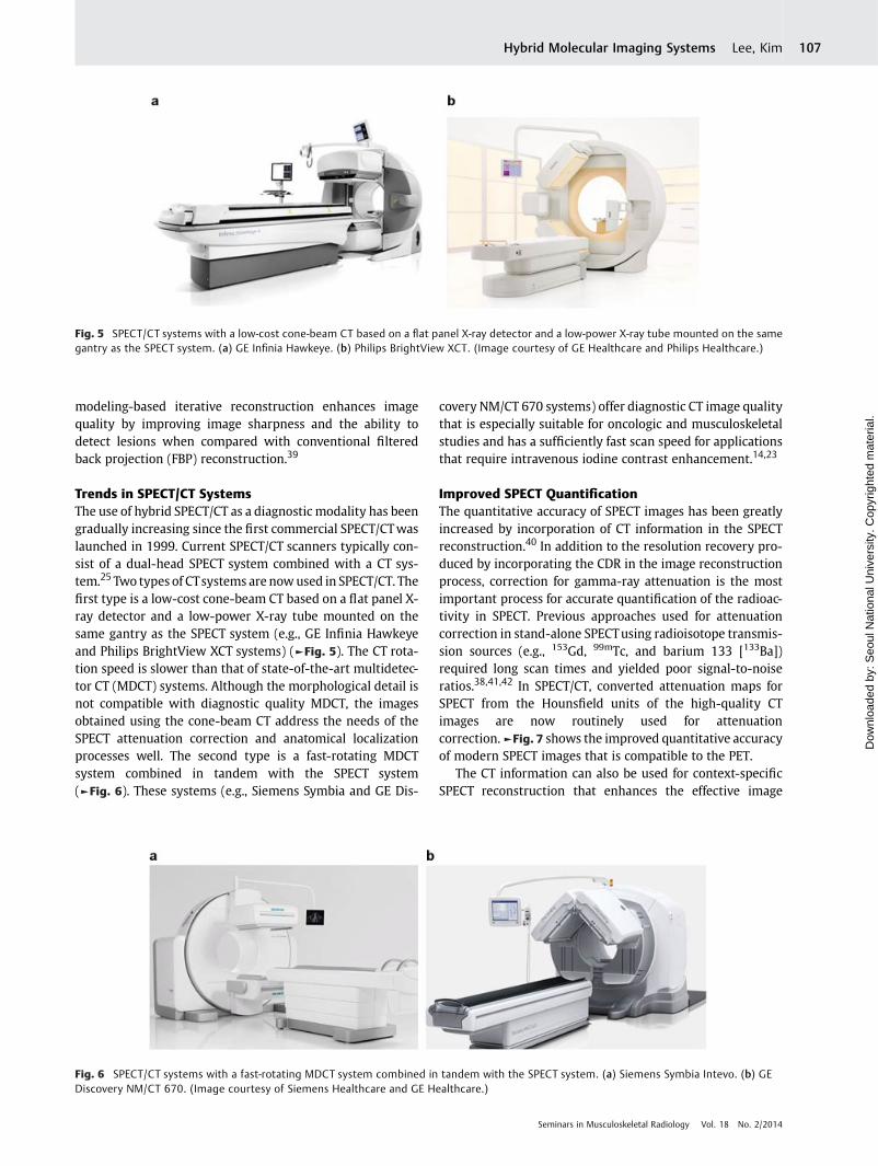
Trends in SPECT/CT SystemsThe use of hybrid SPECT/CT as a diagnostic modality has beengradually increasing since the first commercial SPECT/CTwaslaunched in 1999. Current SPECT/CT scanners typically con-sist of a dual-head SPECT system combined with a CT sys-tem.25 Two types of CTsystems are nowused in SPECT/CT. Thefirst type is a low-cost cone-beam CT based on a flat panel X-ray detector and a low-power X-ray tube mounted on thesame gantry as the SPECT system (e.g., GE Infinia Hawkeyeand Philips BrightView XCT systems) (►Fig. 5). The CT rota-tion speed is slower than that of state-of-the-art multidetec-tor CT (MDCT) systems. Although the morphological detail isnot compatible with diagnostic quality MDCT, the imagesobtained using the cone-beam CT address the needs of theSPECT attenuation correction and anatomical localizationprocesses well. The second type is a fast-rotating MDCTsystem combined in tandem with the SPECT system(►Fig. 6). These systems (e.g., Siemens Symbia and GE Dis-
covery NM/CT 670 systems) offer diagnostic CT image qualitythat is especially suitable for oncologic and musculoskeletalstudies and has a sufficiently fast scan speed for applicationsthat require intravenous iodine contrast enhancement.14,23
Improved SPECT QuantificationThe quantitative accuracy of SPECT images has been greatlyincreased by incorporation of CT information in the SPECTreconstruction.40 In addition to the resolution recovery pro-duced by incorporating the CDR in the image reconstructionprocess, correction for gamma-ray attenuation is the mostimportant process for accurate quantification of the radioac-tivity in SPECT. Previous approaches used for attenuationcorrection in stand-alone SPECTusing radioisotope transmis-sion sources (e.g., 153Gd, 99mTc, and barium 133 [133Ba])required long scan times and yielded poor signal-to-noiseratios.38,41,42 In SPECT/CT, converted attenuation maps forSPECT from the Hounsfield units of the high-quality CTimages are now routinely used for attenuationcorrection.►Fig. 7 shows the improved quantitative accuracyof modern SPECT images that is compatible to the PET.
The CT information can also be used for context-specificSPECT reconstruction that enhances the effective image
Fig. 5 SPECT/CT systems with a low-cost cone-beam CT based on a flat panel X-ray detector and a low-power X-ray tube mounted on the samegantry as the SPECT system. (a) GE Infinia Hawkeye. (b) Philips BrightView XCT. (Image courtesy of GE Healthcare and Philips Healthcare.)
Fig. 6 SPECT/CT systems with a fast-rotating MDCT system combined in tandem with the SPECT system. (a) Siemens Symbia Intevo. (b) GEDiscovery NM/CT 670. (Image courtesy of Siemens Healthcare and GE Healthcare.)
Seminars in Musculoskeletal Radiology Vol. 18 No. 2/2014
Hybrid Molecular Imaging Systems Lee, Kim 107
Dow
nloa
ded
by: S
eoul
Nat
iona
l Uni
vers
ity. C
opyr
ight
ed m
ater
ial.
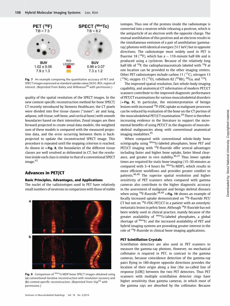
quality of the spatial resolution of the SPECT images. In thenew context-specific reconstruction method for bone SPECT/CT recently introduced by Siemens Healthcare, the CT pixelswere divided into five tissue classes (“zones”: air and lung,adipose, soft tissue, soft bone, and cortical bone) with smoothboundaries based on their intensities. Zonal images are thenforward projected to create zonal data models; the weightedsum of these models is compared with the measured projec-tion data, and the error occurring between them is back-projected to update the reconstructed SPECT image. Thisprocedure is repeated until the stopping criterion is reached.As shown in ►Fig. 8, the boundaries of the different tissueclasses are well resolved as delineated in CT, but the resolu-tion inside each class is similar to that of a conventional SPECTimage.43
Advances in PET/CT
Basic Principles, Advantages, and ApplicationsThe nuclei of the radioisotopes used in PET have relativelysmall numbers of neutrons in comparisonwith those of stable
isotopes. Thus one of the protons inside the radioisotope isconverted into a neutron while releasing a positron, which isthe antiparticle of an electron with the opposite charge. Themutual annihilation of this positron and an electron results inthe simultaneous emission of a pair of annihilation (gamma-ray) photonswith identical energies (511 keV) but in oppositedirections. The radioisotope most widely used in PET isfluorine 18 (18F), which has a � 110-minute half-life and isproduced using a cyclotron. Because of the relatively longhalf-life of 18F, the radiopharmaceuticals labeled with 18F atone location can be provided to the other imaging centers.Other PET radioisotopes include carbon 11 (11C), nitrogen 13(13N), oxygen 15 (15O), rubidium 82 (82Rb), 68Ga, and 124I.
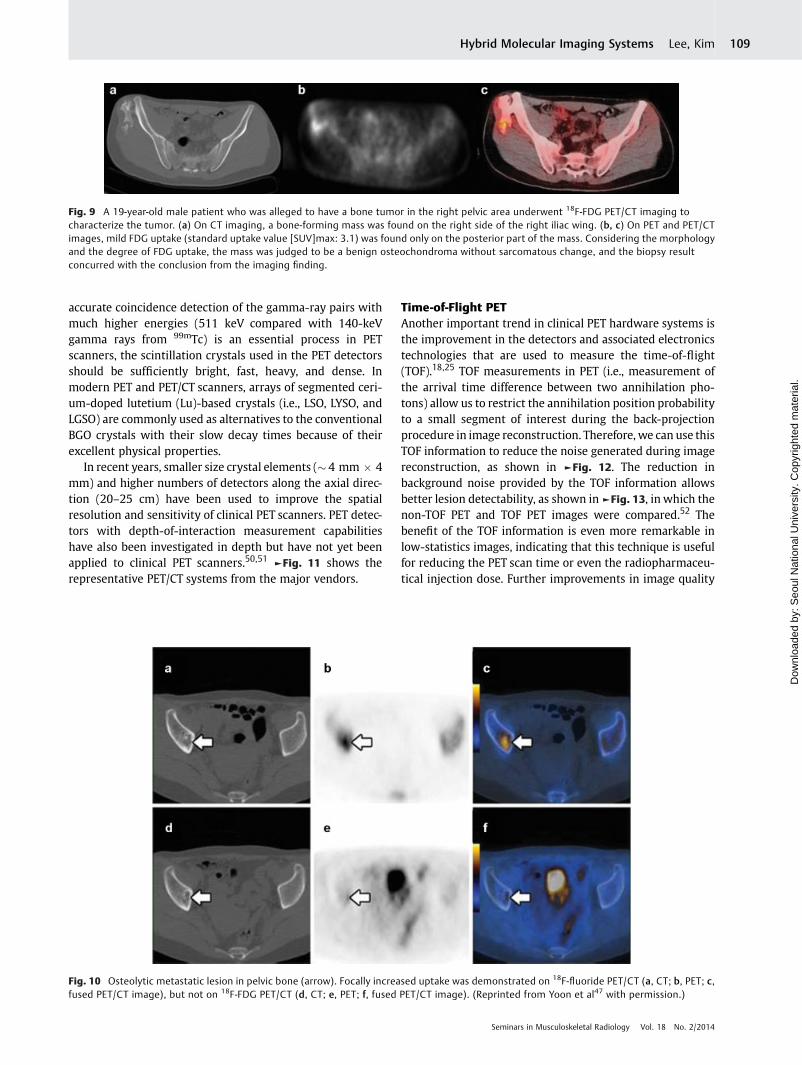
The improved spatial resolution, fast whole-body imagingcapability, and anatomical CT information of modern PET/CTscanners contribute to the improved diagnostic performanceof PET/CT examinations for variousmusculoskeletal disorders(►Fig. 9). In particular, the misinterpretation of benignlesionswith increased 18F-FDGuptake asmalignant processescan be reduced by evaluation of the bone on the CT portion ofthemusculoskeletal PET/CT examination.44 There is thereforeincreasing evidence in the literature to support the incre-mental benefits of using PET/CT in the diagnosis of musculo-skeletal malignancies along with conventional anatomicalimaging modalities.45
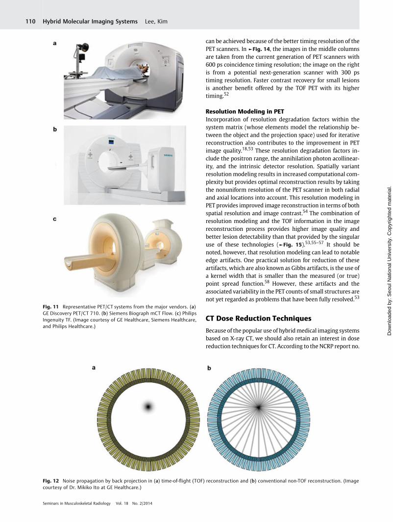
When compared with conventional whole-body bonescintigraphy using 99mTc-labeled phosphates, bone PET andPET/CT imaging with 18F-fluoride offer several advantagesincluding faster and higher bone uptake, faster blood clear-ance, and greater in vivo stability.46,47 Thus lower uptaketimes are required for static bone imaging (15–30 minutes ascompared with 3–4 hours for 99mTc-MDP), which results inmore efficient workflows and provides greater comfort topatients.46,48 The superior spatial resolution and highersensitivity of PET scanners when compared with gammacameras also contribute to the higher diagnostic accuracyin the assessment of malignant and benign skeletal diseaseswhen using 18F-fluoride.48,49 ►Fig. 10 shows an example offocally increased uptake demonstrated on 18F-fluoride PET/CT but not on 18F-FDG PET/CT in a patient with an osteolyticmetastatic lesion in pelvic bone. Although 18F-fluoridehas notbeen widely used in clinical practice, mainly because of thegreater availability of 99mTc-labeled phosphates, a globalshortage of 99mTc and the increased availability of PET andhybrid imaging systems are provoking greater interest in therole of 18F-fluoride in clinical bone imaging applications.
PET Scintillation CrystalsScintillation detectors are also used in PET scanners tomeasure the gamma-ray photons. However, no mechanicalcollimator is required in PET, in contrast to the gammacameras, because coincidence detection of the gamma-raypairs flying in 180-degree opposite directions provides thelocation of their origin along a line (the so-called line ofresponse [LOR]) between the two PET detectors. Thus PETscanners with multiple scintillation detector rings havehigher sensitivity than gamma cameras, in which most ofthe gamma rays are absorbed by the collimator. Because
Fig. 7 An example comparing the quantitative accuracy of PET andSPECT images expressed as standard uptake value (SUV). ROI, region ofinterest. (Reprinted from Bailey and Willowson40 with permission.)
Fig. 8 Comparison of 99mTc-MDP bone SPECT images obtained using(a) conventional iterative reconstruction with resolution recovery and(b) context-specific reconstruction. (Reprinted from Vija43 withpermission.)
Seminars in Musculoskeletal Radiology Vol. 18 No. 2/2014
Hybrid Molecular Imaging Systems Lee, Kim108
Dow
nloa
ded
by: S
eoul
Nat
iona
l Uni
vers
ity. C
opyr
ight
ed m
ater
ial.
accurate coincidence detection of the gamma-ray pairs withmuch higher energies (511 keV compared with 140-keVgamma rays from 99mTc) is an essential process in PETscanners, the scintillation crystals used in the PET detectorsshould be sufficiently bright, fast, heavy, and dense. Inmodern PET and PET/CT scanners, arrays of segmented ceri-um-doped lutetium (Lu)-based crystals (i.e., LSO, LYSO, andLGSO) are commonly used as alternatives to the conventionalBGO crystals with their slow decay times because of theirexcellent physical properties.
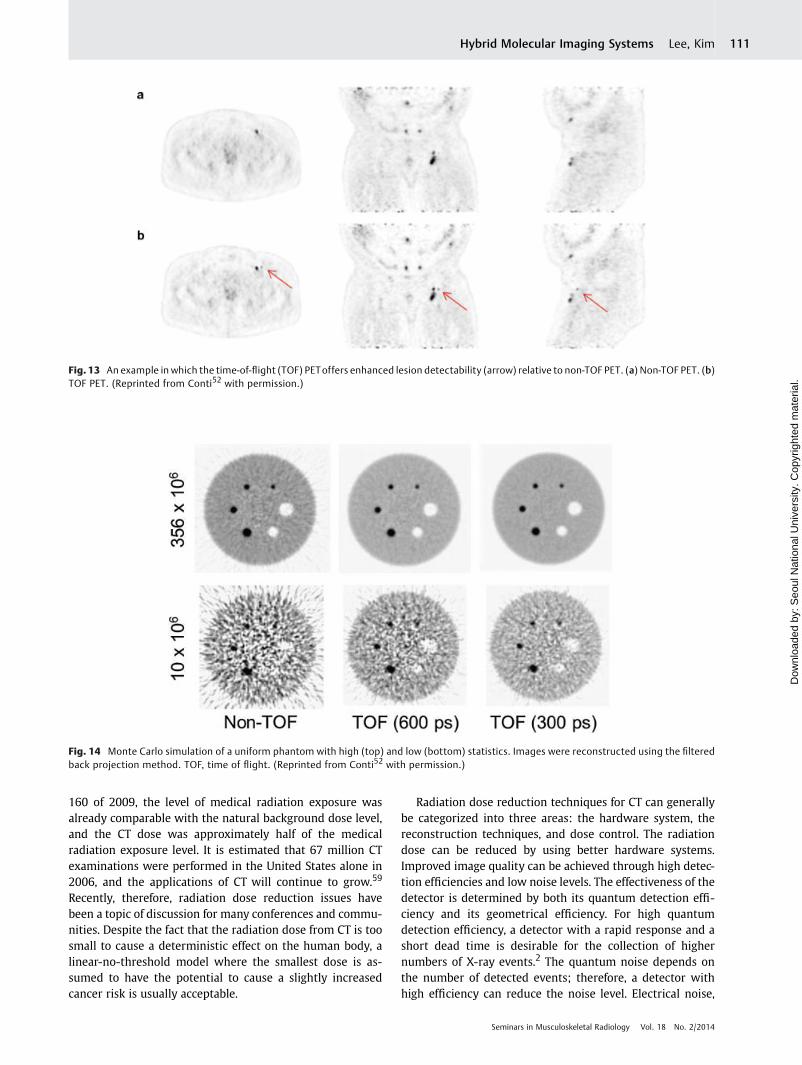
In recent years, smaller size crystal elements (� 4 mm � 4mm) and higher numbers of detectors along the axial direc-tion (20–25 cm) have been used to improve the spatialresolution and sensitivity of clinical PET scanners. PET detec-tors with depth-of-interaction measurement capabilitieshave also been investigated in depth but have not yet beenapplied to clinical PET scanners.50,51 ►Fig. 11 shows therepresentative PET/CT systems from the major vendors.
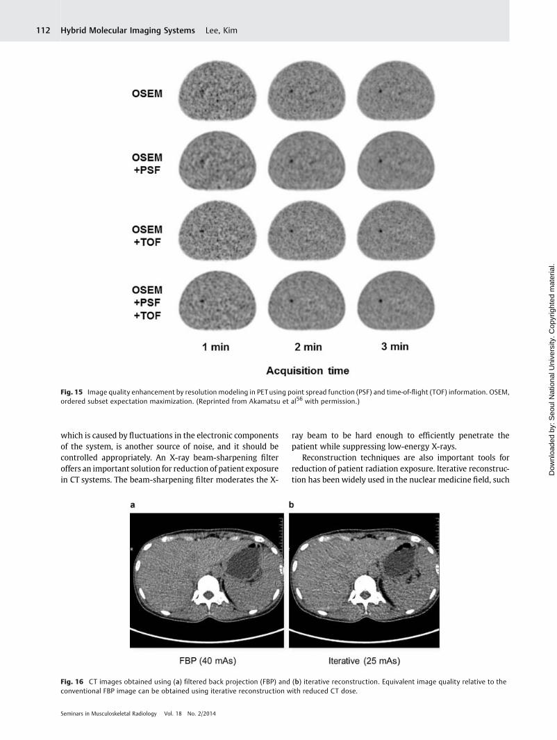
Time-of-Flight PETAnother important trend in clinical PET hardware systems isthe improvement in the detectors and associated electronicstechnologies that are used to measure the time-of-flight(TOF).18,25 TOF measurements in PET (i.e., measurement ofthe arrival time difference between two annihilation pho-tons) allow us to restrict the annihilation position probabilityto a small segment of interest during the back-projectionprocedure in image reconstruction. Therefore, we can use thisTOF information to reduce the noise generated during imagereconstruction, as shown in ►Fig. 12. The reduction inbackground noise provided by the TOF information allowsbetter lesion detectability, as shown in►Fig. 13, in which thenon-TOF PET and TOF PET images were compared.52 Thebenefit of the TOF information is even more remarkable inlow-statistics images, indicating that this technique is usefulfor reducing the PET scan time or even the radiopharmaceu-tical injection dose. Further improvements in image quality
Fig. 9 A 19-year-old male patient who was alleged to have a bone tumor in the right pelvic area underwent 18F-FDG PET/CT imaging tocharacterize the tumor. (a) On CT imaging, a bone-forming mass was found on the right side of the right iliac wing. (b, c) On PET and PET/CTimages, mild FDG uptake (standard uptake value [SUV]max: 3.1) was found only on the posterior part of the mass. Considering the morphologyand the degree of FDG uptake, the mass was judged to be a benign osteochondroma without sarcomatous change, and the biopsy resultconcurred with the conclusion from the imaging finding.
Fig. 10 Osteolytic metastatic lesion in pelvic bone (arrow). Focally increased uptake was demonstrated on 18F-fluoride PET/CT (a, CT; b, PET; c,fused PET/CT image), but not on 18F-FDG PET/CT (d, CT; e, PET; f, fused PET/CT image). (Reprinted from Yoon et al47 with permission.)
Seminars in Musculoskeletal Radiology Vol. 18 No. 2/2014
Hybrid Molecular Imaging Systems Lee, Kim 109
Dow
nloa
ded
by: S
eoul
Nat
iona
l Uni
vers
ity. C
opyr
ight
ed m
ater
ial.
can be achieved because of the better timing resolution of thePET scanners. In ►Fig. 14, the images in the middle columnsare taken from the current generation of PET scanners with600 ps coincidence timing resolution; the image on the rightis from a potential next-generation scanner with 300 pstiming resolution. Faster contrast recovery for small lesionsis another benefit offered by the TOF PET with its highertiming.52
Resolution Modeling in PETIncorporation of resolution degradation factors within thesystem matrix (whose elements model the relationship be-tween the object and the projection space) used for iterativereconstruction also contributes to the improvement in PETimage quality.18,53 These resolution degradation factors in-clude the positron range, the annihilation photon acollinear-ity, and the intrinsic detector resolution. Spatially variantresolution modeling results in increased computational com-plexity but provides optimal reconstruction results by takingthe nonuniform resolution of the PET scanner in both radialand axial locations into account. This resolution modeling inPET provides improved image reconstruction in terms of bothspatial resolution and image contrast.54 The combination ofresolution modeling and the TOF information in the imagereconstruction process provides higher image quality andbetter lesion detectability than that provided by the singularuse of these technologies (►Fig. 15).53,55–57 It should benoted, however, that resolution modeling can lead to notableedge artifacts. One practical solution for reduction of theseartifacts, which are also known as Gibbs artifacts, is the use ofa kernel width that is smaller than the measured (or true)point spread function.58 However, these artifacts and theassociated variability in the PET counts of small structures arenot yet regarded as problems that have been fully resolved.53
CT Dose Reduction Techniques
Because of the popular use of hybridmedical imaging systemsbased on X-ray CT, we should also retain an interest in dosereduction techniques for CT. According to the NCRP report no.
Fig. 11 Representative PET/CT systems from the major vendors. (a)GE Discovery PET/CT 710. (b) Siemens Biograph mCT Flow. (c) PhilipsIngenuity TF. (Image courtesy of GE Healthcare, Siemens Healthcare,and Philips Healthcare.)
Fig. 12 Noise propagation by back projection in (a) time-of-flight (TOF) reconstruction and (b) conventional non-TOF reconstruction. (Imagecourtesy of Dr. Mikiko Ito at GE Healthcare.)
Seminars in Musculoskeletal Radiology Vol. 18 No. 2/2014
Hybrid Molecular Imaging Systems Lee, Kim110
Dow
nloa
ded
by: S
eoul
Nat
iona
l Uni
vers
ity. C
opyr
ight
ed m
ater
ial.
160 of 2009, the level of medical radiation exposure wasalready comparable with the natural background dose level,and the CT dose was approximately half of the medicalradiation exposure level. It is estimated that 67 million CTexaminations were performed in the United States alone in2006, and the applications of CT will continue to grow.59
Recently, therefore, radiation dose reduction issues havebeen a topic of discussion for many conferences and commu-nities. Despite the fact that the radiation dose from CT is toosmall to cause a deterministic effect on the human body, alinear-no-threshold model where the smallest dose is as-sumed to have the potential to cause a slightly increasedcancer risk is usually acceptable.
Radiation dose reduction techniques for CT can generallybe categorized into three areas: the hardware system, thereconstruction techniques, and dose control. The radiationdose can be reduced by using better hardware systems.Improved image quality can be achieved through high detec-tion efficiencies and low noise levels. The effectiveness of thedetector is determined by both its quantum detection effi-ciency and its geometrical efficiency. For high quantumdetection efficiency, a detector with a rapid response and ashort dead time is desirable for the collection of highernumbers of X-ray events.2 The quantum noise depends onthe number of detected events; therefore, a detector withhigh efficiency can reduce the noise level. Electrical noise,
Fig. 13 An example in which the time-of-flight (TOF) PEToffers enhanced lesion detectability (arrow) relative to non-TOF PET. (a) Non-TOF PET. (b)TOF PET. (Reprinted from Conti52 with permission.)
Fig. 14 Monte Carlo simulation of a uniform phantom with high (top) and low (bottom) statistics. Images were reconstructed using the filteredback projection method. TOF, time of flight. (Reprinted from Conti52 with permission.)
Seminars in Musculoskeletal Radiology Vol. 18 No. 2/2014
Hybrid Molecular Imaging Systems Lee, Kim 111
Dow
nloa
ded
by: S
eoul
Nat
iona
l Uni
vers
ity. C
opyr
ight
ed m
ater
ial.
which is caused by fluctuations in the electronic componentsof the system, is another source of noise, and it should becontrolled appropriately. An X-ray beam-sharpening filteroffers an important solution for reduction of patient exposurein CT systems. The beam-sharpening filter moderates the X-
ray beam to be hard enough to efficiently penetrate thepatient while suppressing low-energy X-rays.
Reconstruction techniques are also important tools forreduction of patient radiation exposure. Iterative reconstruc-tion has been widely used in the nuclear medicine field, such
Fig. 15 Image quality enhancement by resolution modeling in PETusing point spread function (PSF) and time-of-flight (TOF) information. OSEM,ordered subset expectation maximization. (Reprinted from Akamatsu et al56 with permission.)
Fig. 16 CT images obtained using (a) filtered back projection (FBP) and (b) iterative reconstruction. Equivalent image quality relative to theconventional FBP image can be obtained using iterative reconstruction with reduced CT dose.
Seminars in Musculoskeletal Radiology Vol. 18 No. 2/2014
Hybrid Molecular Imaging Systems Lee, Kim112
Dow
nloa
ded
by: S
eoul
Nat
iona
l Uni
vers
ity. C
opyr
ight
ed m
ater
ial.
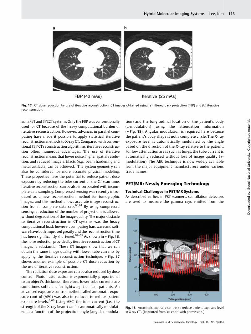
as in PET and SPECTsystems. Only the FBP was conventionallyused for CT because of the heavy computational burden ofiterative reconstruction. However, advances in parallel com-puting have made it possible to apply statistical iterativereconstruction methods to X-ray CT. Compared with conven-tional FBP CT reconstruction algorithms, iterative reconstruc-tion offers numerous advantages. The use of iterativereconstruction means that lower noise, higher spatial resolu-tion, and reduced image artifacts (e.g., beam hardening andmetal artifacts) can be achieved.3 The system geometry canalso be considered for more accurate physical modeling.These properties have the potential to reduce patient doseexposure by reducing the tube current or the CT scan time.Iterative reconstruction can be also incorporatedwith incom-plete data sampling. Compressed sensing was recently intro-duced as a new reconstruction method for tomographicimages, and this method allows accurate image reconstruc-tion from incomplete data sets.60,61 By using compressedsensing, a reduction of the number of projections is allowedwithout degradation of the image quality. The major obstacleto iterative reconstruction in CT systems was the heavycomputational load; however, computing hardware and soft-ware have both improved greatly and the reconstruction timehas been significantly shortened.62–65 As shown in ►Fig. 16,the noise reduction provided by iterative reconstruction of CTimages is substantial. These CT images show that we canobtain the same image quality with lower tube currents byapplying the iterative reconstruction technique. ►Fig. 17
shows another example of possible CT dose reduction bythe use of iterative reconstruction.
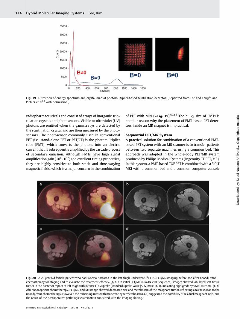
The radiation dose exposure can be also reduced by dosecontrol. Photon attenuation is exponentially proportionalto an object’s thickness; therefore, lower tube currents aresometimes sufficient for lightweight or lean patients. Anadvanced exposure control method called automatic expo-sure control (AEC) was also introduced to reduce patientexposure levels.3,66 Using AEC, the tube current (i.e., thestrength of the X-ray beam) can be automatically modulat-ed as a function of the projection angle (angular modula-
tion) and the longitudinal location of the patient’s body(z-modulation) using the attenuation information(►Fig. 18). Angular modulation is required here becausethe patient’s body shape is not a complete circle. The X-rayexposure level is automatically modulated by the anglebased on the direction of the X-ray relative to the patient.For low attenuation areas such as lungs, the tube current isautomatically reduced without loss of image quality (z-modulation). The AEC technique is now widely availablefrom the major equipment manufacturers under varioustrade names.
PET/MR: Newly Emerging Technology
Technical Challenges in PET/MR SystemsAs described earlier, in PET scanners, scintillation detectorsare used to measure the gamma rays emitted from the
Fig. 17 CT dose reduction by use of iterative reconstruction. CT images obtained using (a) filtered back projection (FBP) and (b) iterativereconstruction.
Fig. 18 Automatic exposure control to reduce patient exposure levelin X-ray CT. (Reprinted from Yu et al3 with permission.)
Seminars in Musculoskeletal Radiology Vol. 18 No. 2/2014
Hybrid Molecular Imaging Systems Lee, Kim 113
Dow
nloa
ded
by: S
eoul
Nat
iona
l Uni
vers
ity. C
opyr
ight
ed m
ater
ial.
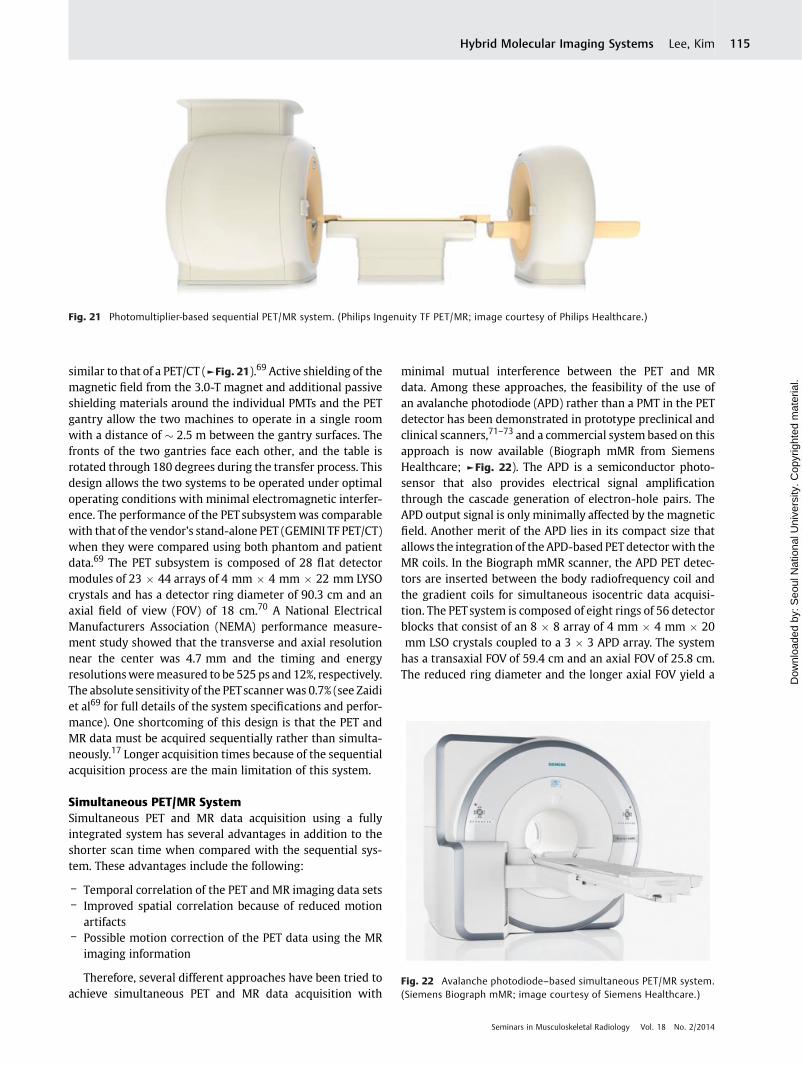
radiopharmaceuticals and consist of arrays of inorganic scin-tillation crystals and photosensors. Visible or ultraviolet (UV)photons are emitted when the gamma rays are detected bythe scintillation crystal and are then measured by the photo-sensors. The photosensor commonly used in conventionalPET (i.e., stand-alone PET or PET/CT) is the photomultipliertube (PMT), which converts the photons into an electriccurrent that is subsequently amplified by the cascade processof secondary emission. Although PMTs have high signalamplification gain (106–107) and excellent timing properties,they are highly sensitive to both static and time-varyingmagnetic fields, which is a major concern in the combination
of PET with MRI (►Fig. 19).67,68 The bulky size of PMTs isanother reason why the placement of PMT-based PET detec-tors inside an MR magnet is impractical.
Sequential PET/MR SystemA practical solution for combination of a conventional PMT-based PET system with an MR scanner is to transfer patientsbetween two separate machines using a common bed. Thisapproach was adopted in the whole-body PET/MR systemproduced by Philips Medical Systems (Ingenuity TF PET/MR).In this system, a PMT-based TOF PET is combinedwith a 3.0-TMRI with a common bed and a common computer console
Fig. 19 Distortion of energy spectrum and crystal map of photomultiplier-based scintillation detector. (Reprinted from Lee and Kang67 andPichler et al68 with permission.)
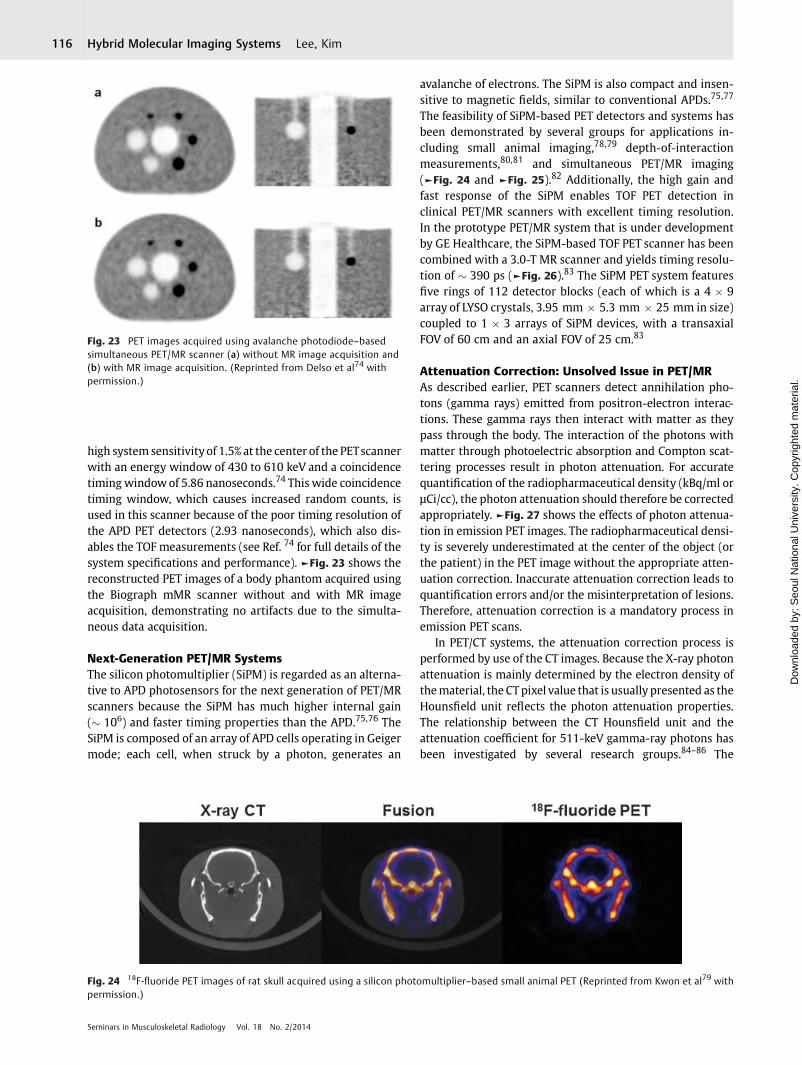
Fig. 20 A 26-year-old female patient who had synovial sarcoma in the left thigh underwent 18F-FDG PET/MR imaging before and after neoadjuvantchemotherapy for staging and to evaluate the treatment efficacy. (a, b) On initial PET/MR (DIXON VIBE sequence), images showed lobulated soft tissuetumor in the posterior aspect of left thigh with intense FDG uptake (standard uptake value [SUV]max: 16.3), indicating high-grade synovial sarcoma. (c, d)After neoadjuvant chemotherapy, PET/MR and MR image showed decreased size and metabolism of the malignant tumor, reflecting a fair response to theneoadjuvant chemotherapy. However, the remaining mass withmoderate hypermetabolism (4.6) suggested the possibility of residual malignant cells, andthe result of the postoperative pathologic examination concurred with the imaging finding.
Seminars in Musculoskeletal Radiology Vol. 18 No. 2/2014
Hybrid Molecular Imaging Systems Lee, Kim114
Dow
nloa
ded
by: S
eoul
Nat
iona
l Uni
vers
ity. C
opyr
ight
ed m
ater
ial.
similar to that of a PET/CT (►Fig. 21).69 Active shielding of themagnetic field from the 3.0-T magnet and additional passiveshielding materials around the individual PMTs and the PETgantry allow the two machines to operate in a single roomwith a distance of � 2.5 m between the gantry surfaces. Thefronts of the two gantries face each other, and the table isrotated through 180 degrees during the transfer process. Thisdesign allows the two systems to be operated under optimaloperating conditions with minimal electromagnetic interfer-ence. The performance of the PET subsystemwas comparablewith that of the vendor’s stand-alone PET (GEMINI TF PET/CT)when they were compared using both phantom and patientdata.69 The PET subsystem is composed of 28 flat detectormodules of 23 � 44 arrays of 4 mm � 4 mm � 22 mm LYSOcrystals and has a detector ring diameter of 90.3 cm and anaxial field of view (FOV) of 18 cm.70 A National ElectricalManufacturers Association (NEMA) performance measure-ment study showed that the transverse and axial resolutionnear the center was 4.7 mm and the timing and energyresolutionsweremeasured to be 525 ps and 12%, respectively.The absolute sensitivity of the PETscanner was 0.7% (see Zaidiet al69 for full details of the system specifications and perfor-mance). One shortcoming of this design is that the PET andMR data must be acquired sequentially rather than simulta-neously.17 Longer acquisition times because of the sequentialacquisition process are the main limitation of this system.
Simultaneous PET/MR SystemSimultaneous PET and MR data acquisition using a fullyintegrated system has several advantages in addition to theshorter scan time when compared with the sequential sys-tem. These advantages include the following:
– Temporal correlation of the PET and MR imaging data sets– Improved spatial correlation because of reduced motion
artifacts– Possible motion correction of the PET data using the MR
imaging information
Therefore, several different approaches have been tried toachieve simultaneous PET and MR data acquisition with
minimal mutual interference between the PET and MRdata. Among these approaches, the feasibility of the use ofan avalanche photodiode (APD) rather than a PMT in the PETdetector has been demonstrated in prototype preclinical andclinical scanners,71–73 and a commercial system based on thisapproach is now available (Biograph mMR from SiemensHealthcare; ►Fig. 22). The APD is a semiconductor photo-sensor that also provides electrical signal amplificationthrough the cascade generation of electron-hole pairs. TheAPD output signal is only minimally affected by the magneticfield. Another merit of the APD lies in its compact size thatallows the integration of the APD-based PET detector with theMR coils. In the Biograph mMR scanner, the APD PET detec-tors are inserted between the body radiofrequency coil andthe gradient coils for simultaneous isocentric data acquisi-tion. The PETsystem is composed of eight rings of 56 detectorblocks that consist of an 8 � 8 array of 4 mm � 4 mm � 20mm LSO crystals coupled to a 3 � 3 APD array. The systemhas a transaxial FOV of 59.4 cm and an axial FOV of 25.8 cm.The reduced ring diameter and the longer axial FOV yield a
Fig. 22 Avalanche photodiode–based simultaneous PET/MR system.(Siemens Biograph mMR; image courtesy of Siemens Healthcare.)
Fig. 21 Photomultiplier-based sequential PET/MR system. (Philips Ingenuity TF PET/MR; image courtesy of Philips Healthcare.)
Seminars in Musculoskeletal Radiology Vol. 18 No. 2/2014
Hybrid Molecular Imaging Systems Lee, Kim 115
Dow
nloa
ded
by: S
eoul
Nat
iona
l Uni
vers
ity. C
opyr
ight
ed m
ater
ial.
high system sensitivity of 1.5% at the center of the PETscannerwith an energy window of 430 to 610 keV and a coincidencetiming windowof 5.86 nanoseconds.74 This wide coincidencetiming window, which causes increased random counts, isused in this scanner because of the poor timing resolution ofthe APD PET detectors (2.93 nanoseconds), which also dis-ables the TOF measurements (see Ref. 74 for full details of thesystem specifications and performance). ►Fig. 23 shows thereconstructed PET images of a body phantom acquired usingthe Biograph mMR scanner without and with MR imageacquisition, demonstrating no artifacts due to the simulta-neous data acquisition.
Next-Generation PET/MR SystemsThe silicon photomultiplier (SiPM) is regarded as an alterna-tive to APD photosensors for the next generation of PET/MRscanners because the SiPM has much higher internal gain(� 106) and faster timing properties than the APD.75,76 TheSiPM is composed of an array of APD cells operating in Geigermode; each cell, when struck by a photon, generates an
avalanche of electrons. The SiPM is also compact and insen-sitive to magnetic fields, similar to conventional APDs.75,77
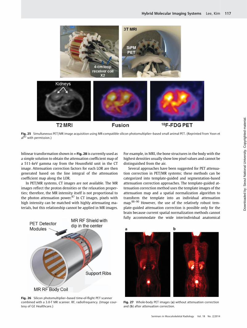
The feasibility of SiPM-based PET detectors and systems hasbeen demonstrated by several groups for applications in-cluding small animal imaging,78,79 depth-of-interactionmeasurements,80,81 and simultaneous PET/MR imaging(►Fig. 24 and ►Fig. 25).82 Additionally, the high gain andfast response of the SiPM enables TOF PET detection inclinical PET/MR scanners with excellent timing resolution.In the prototype PET/MR system that is under developmentby GE Healthcare, the SiPM-based TOF PET scanner has beencombined with a 3.0-T MR scanner and yields timing resolu-tion of � 390 ps (►Fig. 26).83 The SiPM PET system featuresfive rings of 112 detector blocks (each of which is a 4 � 9array of LYSO crystals, 3.95 mm � 5.3 mm � 25 mm in size)coupled to 1 � 3 arrays of SiPM devices, with a transaxialFOV of 60 cm and an axial FOV of 25 cm.83
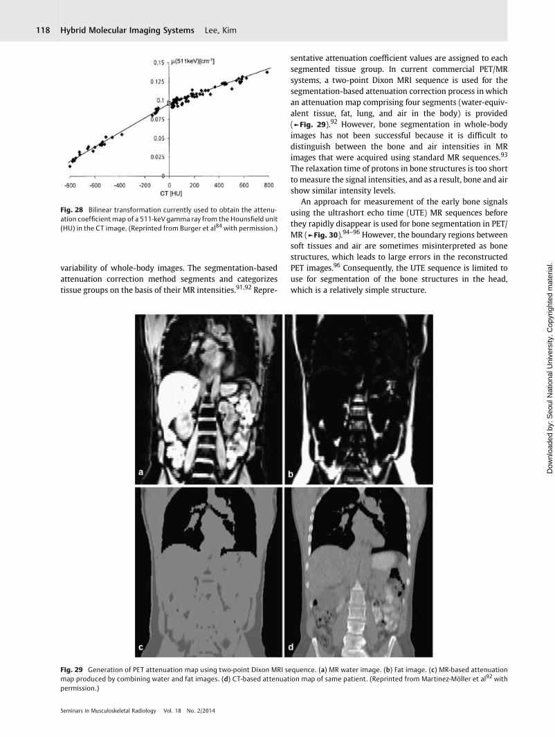
Attenuation Correction: Unsolved Issue in PET/MRAs described earlier, PET scanners detect annihilation pho-tons (gamma rays) emitted from positron-electron interac-tions. These gamma rays then interact with matter as theypass through the body. The interaction of the photons withmatter through photoelectric absorption and Compton scat-tering processes result in photon attenuation. For accuratequantification of the radiopharmaceutical density (kBq/ml orμCi/cc), the photon attenuation should therefore be correctedappropriately. ►Fig. 27 shows the effects of photon attenua-tion in emission PET images. The radiopharmaceutical densi-ty is severely underestimated at the center of the object (orthe patient) in the PET image without the appropriate atten-uation correction. Inaccurate attenuation correction leads toquantification errors and/or the misinterpretation of lesions.Therefore, attenuation correction is a mandatory process inemission PET scans.
In PET/CT systems, the attenuation correction process isperformed by use of the CT images. Because the X-ray photonattenuation is mainly determined by the electron density ofthematerial, the CT pixel value that is usually presented as theHounsfield unit reflects the photon attenuation properties.The relationship between the CT Hounsfield unit and theattenuation coefficient for 511-keV gamma-ray photons hasbeen investigated by several research groups.84–86 The
Fig. 23 PET images acquired using avalanche photodiode–basedsimultaneous PET/MR scanner (a) without MR image acquisition and(b) with MR image acquisition. (Reprinted from Delso et al74 withpermission.)
Fig. 24 18F-fluoride PET images of rat skull acquired using a silicon photomultiplier–based small animal PET (Reprinted from Kwon et al79 withpermission.)
Seminars in Musculoskeletal Radiology Vol. 18 No. 2/2014
Hybrid Molecular Imaging Systems Lee, Kim116
Dow
nloa
ded
by: S
eoul
Nat
iona
l Uni
vers
ity. C
opyr
ight
ed m
ater
ial.
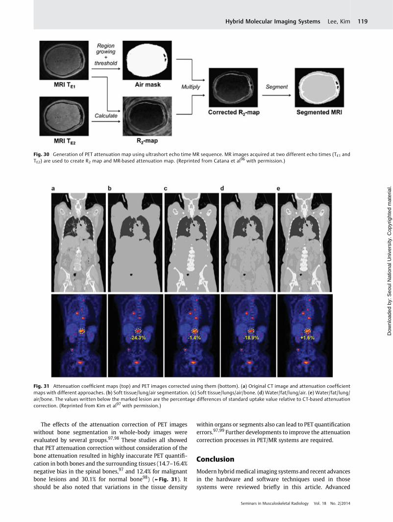
bilinear transformation shown in►Fig. 28 is currently used asa simple solution to obtain the attenuation coefficient map ofa 511-keV gamma ray from the Hounsfield unit in the CTimage. Attenuation correction factors for each LOR are thengenerated based on the line integral of the attenuationcoefficient map along the LOR.
In PET/MR systems, CT images are not available. The MRimages reflect the proton densities or the relaxation proper-ties; therefore, the MR intensity itself is not proportional tothe photon attenuation power.87 In CT images, pixels withhigh intensity can be matched with highly attenuating ma-terials, but this relationship cannot be applied in MR images.
For example, in MRI, the bone structures in the body with thehighest densities usually show low pixel values and cannot bedistinguished from the air.
Several approaches have been suggested for PET attenua-tion correction in PET/MR systems; these methods can becategorized into template-guided and segmentation-basedattenuation correction approaches. The template-guided at-tenuation correction method uses the template images of theattenuation map and a spatial normalization algorithm totransform the template into an individual attenuationmap.88–90 However, the use of the relatively robust tem-plate-guided attenuation correction is possible only for thebrain because current spatial normalization methods cannotfully accommodate the wide interindividual anatomical
Fig. 25 Simultaneous PET/MR image acquisition using MR-compatible silicon photomultiplier–based small animal PET. (Reprinted from Yoon etal82 with permission.)
Fig. 26 Silicon photomultiplier–based time-of-flight PET scannercombined with a 3.0-T MR scanner. RF, radiofrequency. (Image cour-tesy of GE Healthcare.)
Fig. 27 Whole-body PET images (a) without attenuation correctionand (b) after attenuation correction.
Seminars in Musculoskeletal Radiology Vol. 18 No. 2/2014
Hybrid Molecular Imaging Systems Lee, Kim 117
Dow
nloa
ded
by: S
eoul
Nat
iona
l Uni
vers
ity. C
opyr
ight
ed m
ater
ial.
variability of whole-body images. The segmentation-basedattenuation correction method segments and categorizestissue groups on the basis of their MR intensities.91,92 Repre-
sentative attenuation coefficient values are assigned to eachsegmented tissue group. In current commercial PET/MRsystems, a two-point Dixon MRI sequence is used for thesegmentation-based attenuation correction process in whichan attenuation map comprising four segments (water-equiv-alent tissue, fat, lung, and air in the body) is provided(►Fig. 29).92 However, bone segmentation in whole-bodyimages has not been successful because it is difficult todistinguish between the bone and air intensities in MRimages that were acquired using standard MR sequences.93
The relaxation time of protons in bone structures is too shortto measure the signal intensities, and as a result, bone and airshow similar intensity levels.
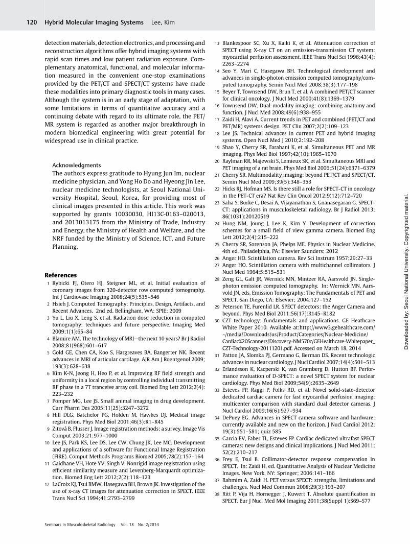
An approach for measurement of the early bone signalsusing the ultrashort echo time (UTE) MR sequences beforethey rapidly disappear is used for bone segmentation in PET/MR (►Fig. 30).94–96 However, the boundary regions betweensoft tissues and air are sometimes misinterpreted as bonestructures, which leads to large errors in the reconstructedPET images.96 Consequently, the UTE sequence is limited touse for segmentation of the bone structures in the head,which is a relatively simple structure.
Fig. 28 Bilinear transformation currently used to obtain the attenu-ation coefficient map of a 511-keV gamma ray from the Hounsfield unit(HU) in the CT image. (Reprinted from Burger et al84 with permission.)
Fig. 29 Generation of PET attenuation map using two-point Dixon MRI sequence. (a) MR water image. (b) Fat image. (c) MR-based attenuationmap produced by combining water and fat images. (d) CT-based attenuation map of same patient. (Reprinted from Martinez-Möller et al92 withpermission.)
Seminars in Musculoskeletal Radiology Vol. 18 No. 2/2014
Hybrid Molecular Imaging Systems Lee, Kim118
Dow
nloa
ded
by: S
eoul
Nat
iona
l Uni
vers
ity. C
opyr
ight
ed m
ater
ial.
The effects of the attenuation correction of PET imageswithout bone segmentation in whole-body images wereevaluated by several groups.97,98 These studies all showedthat PET attenuation correction without consideration of thebone attenuation resulted in highly inaccurate PET quantifi-cation in both bones and the surrounding tissues (14.7–16.4%negative bias in the spinal bones,97 and 12.4% for malignantbone lesions and 30.1% for normal bone98) (►Fig. 31). Itshould be also noted that variations in the tissue density
within organs or segments also can lead to PET quantificationerrors.97,99 Further developments to improve the attenuationcorrection processes in PET/MR systems are required.
Conclusion
Modern hybridmedical imaging systems and recent advancesin the hardware and software techniques used in thosesystems were reviewed briefly in this article. Advanced
Fig. 30 Generation of PET attenuation map using ultrashort echo time MR sequence. MR images acquired at two different echo times (TE1 andTE2) are used to create R2 map and MR-based attenuation map. (Reprinted from Catana et al96 with permission.)
Fig. 31 Attenuation coefficient maps (top) and PET images corrected using them (bottom). (a) Original CT image and attenuation coefficientmaps with different approaches. (b) Soft tissue/lung/air segmentation. (c) Soft tissue/lungs/air/bone. (d) Water/fat/lung/air. (e) Water/fat/lung/air/bone. The values written below the marked lesion are the percentage differences of standard uptake value relative to CT-based attenuationcorrection. (Reprinted from Kim et al97 with permission.)
Seminars in Musculoskeletal Radiology Vol. 18 No. 2/2014
Hybrid Molecular Imaging Systems Lee, Kim 119
Dow
nloa
ded
by: S
eoul
Nat
iona
l Uni
vers
ity. C
opyr
ight
ed m
ater
ial.
detectionmaterials, detection electronics, and processing andreconstruction algorithms offer hybrid imaging systems withrapid scan times and low patient radiation exposure. Com-plementary anatomical, functional, and molecular informa-tion measured in the convenient one-stop examinationsprovided by the PET/CT and SPECT/CT systems have madethese modalities into primary diagnostic tools in many cases.Although the system is in an early stage of adaptation, withsome limitations in terms of quantitative accuracy and acontinuing debate with regard to its ultimate role, the PET/MR system is regarded as another major breakthrough inmodern biomedical engineering with great potential forwidespread use in clinical practice.
AcknowledgmentsThe authors express gratitude to Hyung Jun Im, nuclearmedicine physician, and Yong Ho Do and Hyeong Jin Lee,nuclear medicine technologists, at Seoul National Uni-versity Hospital, Seoul, Korea, for providing most ofclinical images presented in this article. This work wassupported by grants 10030030, HI13C-0163–020013,and 2013013175 from the Ministry of Trade, Industryand Energy, the Ministry of Health and Welfare, and theNRF funded by the Ministry of Science, ICT, and FuturePlanning.
References1 Rybicki FJ, Otero HJ, Steigner ML, et al. Initial evaluation of
coronary images from 320-detector row computed tomography.Int J Cardiovasc Imaging 2008;24(5):535–546
2 Hsieh J. Computed Tomography: Principles, Design, Artifacts, andRecent Advances. 2nd ed. Bellingham, WA: SPIE; 2009
3 Yu L, Liu X, Leng S, et al. Radiation dose reduction in computedtomography: techniques and future perspective. Imaging Med2009;1(1):65–84
4 Blamire AM. The technology of MRI—the next 10 years? Br J Radiol2008;81(968):601–617
5 Gold GE, Chen CA, Koo S, Hargreaves BA, Bangerter NK. Recentadvances in MRI of articular cartilage. AJR Am J Roentgenol 2009;193(3):628–638
6 Kim K-N, Jeong H, Heo P, et al. Improving RF field strength anduniformity in a local region by controlling individual transmittingRF phase in a 7T tranceive array coil. Biomed Eng Lett 2012;2(4):223–232
7 Pomper MG, Lee JS. Small animal imaging in drug development.Curr Pharm Des 2005;11(25):3247–3272
8 Hill DLG, Batchelor PG, Holden M, Hawkes DJ. Medical imageregistration. Phys Med Biol 2001;46(3):R1–R45
9 Zitová B, Flusser J. Image registrationmethods: a survey. Image VisComput 2003;21:977–1000
10 Lee JS, Park KS, Lee DS, Lee CW, Chung JK, Lee MC. Developmentand applications of a software for Functional Image Registration(FIRE). Comput Methods Programs Biomed 2005;78(2):157–164
11 Gaidhane VH, Hote YV, Singh V. Nonrigid image registration usingefficient similarity measure and Levenberg-Marquardt optimiza-tion. Biomed Eng Lett 2012;2(2):118–123
12 LaCroix KJ, Tsui BMW,Hasegawa BH, Brown JK. Investigation of theuse of x-ray CT images for attenuation correction in SPECT. IEEETrans Nucl Sci 1994;41:2793–2799
13 Blankespoor SC, Xu X, Kaiki K, et al. Attenuation correction ofSPECT using X-ray CT on an emission-transmission CT system:myocardial perfusion assessment. IEEE Trans Nucl Sci 1996;43(4):2263–2274
14 Seo Y, Mari C, Hasegawa BH. Technological development andadvances in single-photon emission computed tomography/com-puted tomography. Semin Nucl Med 2008;38(3):177–198
15 Beyer T, Townsend DW, Brun T, et al. A combined PET/CT scannerfor clinical oncology. J Nucl Med 2000;41(8):1369–1379
16 Townsend DW. Dual-modality imaging: combining anatomy andfunction. J Nucl Med 2008;49(6):938–955
17 Zaidi H, Alavi A. Current trends in PET and combined (PET/CT andPET/MR) systems design. PET Clin 2007;2(2):109–123
18 Lee JS. Technical advances in current PET and hybrid imagingsystems. Open Nucl Med J 2010;2:192–208
19 Shao Y, Cherry SR, Farahani K, et al. Simultaneous PET and MRimaging. Phys Med Biol 1997;42(10):1965–1970
20 Raylman RR, Majewski S, Lemieux SK, et al. Simultaneous MRI andPET imaging of a rat brain. Phys Med Biol 2006;51(24):6371–6379
21 Cherry SR. Multimodality imaging: beyond PET/CT and SPECT/CT.Semin Nucl Med 2009;39(5):348–353
22 Hicks RJ, Hofman MS. Is there still a role for SPECT-CT in oncologyin the PET-CT era? Nat Rev Clin Oncol 2012;9(12):712–720
23 Saha S, Burke C, Desai A, Vijayanathan S, Gnanasegaran G. SPECT-CT: applications in musculoskeletal radiology. Br J Radiol 2013;86(1031):20120519
24 Hung NM, Joung J, Lee K, Kim Y. Development of correctionschemes for a small field of view gamma camera. Biomed EngLett 2012;2(4):215–222
25 Cherry SR, Sorenson JA, Phelps ME. Physics in Nuclear Medicine.4th ed. Philadelphia, PA: Elsevier Saunders; 2012
26 Anger HO. Scintillation camera. Rev Sci Instrum 1957;29:27–3327 Anger HO. Scintillation camera with multichannel collimators. J
Nucl Med 1964;5:515–53128 Zeng GL, Galt JR, Wernick MN, Mintzer RA, Aarsvold JN. Single-
photon emission computed tomography. In: Wernick MN, Aars-vold JN, eds. Emission Tomography: The Fundamentals of PET andSPECT. San Diego, CA: Elsevier; 2004:127–152
29 Peterson TE, Furenlid LR. SPECT detectors: the Anger Camera andbeyond. Phys Med Biol 2011;56(17):R145–R182
30 CZT technology: fundamentals and applications. GE HeathcareWhite Paper 2010. Available at:http://www3.gehealthcare.com/~/media/Downloads/us/Product/Categories/Nuclear-Medicine/Cardiac%20Scanners/Discovery-NM570c/GEHealthcare-Whitepaper_CZT-Technology-20111201.pdf. Accessed on March 18, 2014
31 Patton JA, Slomka PJ, Germano G, Berman DS. Recent technologicadvances in nuclear cardiology. J Nucl Cardiol 2007;14(4):501–513
32 Erlandsson K, Kacperski K, van Gramberg D, Hutton BF. Perfor-mance evaluation of D-SPECT: a novel SPECT system for nuclearcardiology. Phys Med Biol 2009;54(9):2635–2649
33 Esteves FP, Raggi P, Folks RD, et al. Novel solid-state-detectordedicated cardiac camera for fast myocardial perfusion imaging:multicenter comparison with standard dual detector cameras. JNucl Cardiol 2009;16(6):927–934
34 DePuey EG. Advances in SPECT camera software and hardware:currently available and new on the horizon. J Nucl Cardiol 2012;19(3):551–581; quiz 585
35 Garcia EV, Faber TL, Esteves FP. Cardiac dedicated ultrafast SPECTcameras: new designs and clinical implications. J Nucl Med 2011;52(2):210–217
36 Frey E, Tsui B. Collimator-detector response compensation inSPECT. In: Zaidi H, ed. Quantitative Analysis of Nuclear MedicineImages. New York, NY: Springer; 2006:141–166
37 Rahmim A, Zaidi H. PET versus SPECT: strengths, limitations andchallenges. Nucl Med Commun 2008;29(3):193–207
38 Ritt P, Vija H, Hornegger J, Kuwert T. Absolute quantification inSPECT. Eur J Nucl Med Mol Imaging 2011;38(Suppl 1):S69–S77
Seminars in Musculoskeletal Radiology Vol. 18 No. 2/2014
Hybrid Molecular Imaging Systems Lee, Kim120
Dow
nloa
ded
by: S
eoul
Nat
iona
l Uni
vers
ity. C
opyr
ight
ed m
ater
ial.

39 Stansfield EC, Sheehy N, Zurakowski D, Vija AH, Fahey FH, TrevesST. Pediatric 99mTc-MDP bone SPECTwith ordered subset expec-tation maximization iterative reconstruction with isotropic 3Dresolution recovery. Radiology 2010;257(3):793–801
40 BaileyDL,WillowsonKP. An evidence-based reviewof quantitativeSPECT imaging and potential clinical applications. J Nucl Med2013;54(1):83–89
41 Bailey DL. Transmission scanning in emission tomography. Eur JNucl Med 1998;25(7):774–787
42 Zaidi H, Hasegawa B. Determination of the attenuation map inemission tomography. J Nucl Med 2003;44(2):291–315
43 Vija H. Introduction to xSPECT technology: evolving multi-modalSPECT to become context-based and quantitative. Siemens Medi-cal Solutions USA Inc. White Paper 2013. Available at:http://www.healthcare.siemens.com/siemens_hwem-hwen_ssxa_websites-con-text-root/wcm/idc/groups/public/@global/@imaging/@molecular/documents/download/mdax/ote3/~edisp/xspect_technical_white_paper-00957532.pdf. Accessed on: March 18, 2014
44 Costelloe CM, Murphy WA Jr, Chasen BA. Musculoskeletal pitfallsin 18F-FDG PET/CT: pictorial review. AJR Am J Roentgenol 2009;193(3, Suppl):WS1–WS13; quiz S26–S30
45 Lakkaraju A, Patel CN, Bradley KM, Scarsbrook AF. PET/CT inprimary musculoskeletal tumours: a step forward. Eur Radiol2010;20(12):2959–2972
46 Fischer DR. Musculoskeletal imaging using fluoride PET. SeminNucl Med 2013;43(6):427–433
47 Yoon SH, Kim KS, Kang SY, et al. Usefulness of 18F-fluoride PET/CTin breast cancer patients with osteosclerotic bone metastases.Nucl Med Mol Imaging 2013;47(1):27–35
48 Grant FD, Fahey FH, Packard AB, Davis RT, Alavi A, Treves ST.Skeletal PETwith 18F-fluoride: applying new technology to an oldtracer. J Nucl Med 2008;49(1):68–78
49 Kang JY, Lee WW, So Y, Lee BC, Kim SE. Clinical usefulness of 18F-fluoride bone PET. Nucl Med Mol Imaging 2010;44(1):55–61
50 Lewellen TK. Recent developments in PET detector technology.Phys Med Biol 2008;53(17):R287–R317
51 Ito M, Hong SJ, Lee JS. Positron emission tomography (PET)detectors with depth-of-interaction (DOI) capability. BiomedEng Lett 2011;1(2):70–81
52 Conti M. Focus on time-of-flight PET: the benefits of improved timeresolution. Eur J Nucl Med Mol Imaging 2011;38(6):1147–1157
53 Rahmim A, Qi J, Sossi V. Resolution modeling in PET imaging:theory, practice, benefits, andpitfalls.MedPhys 2013;40(6):064301
54 Alessio AM, Kinahan PE, Lewellen TK. Modeling and incorporationof system response functions in 3D whole body PET. IEEE Nucl SciSymp Conf Rec 2004;6:3992–3996
55 Kadrmas DJ, Casey ME, Conti M, Jakoby BW, Lois C, Townsend DW.Impact of time-of-flight on PET tumor detection. J Nucl Med 2009;50(8):1315–1323
56 Akamatsu G, Ishikawa K, Mitsumoto K, et al. Improvement in PET/CT image quality with a combination of point-spread function andtime-of-flight in relation to reconstruction parameters. J NuclMed2012;53(11):1716–1722
57 Schaefferkoetter J, Casey M, Townsend D, El Fakhri G. Clinicalimpact of time-of-flight and point response modeling in PETreconstructions: a lesion detection study. Phys Med Biol 2013;58(5):1465–1478
58 Watson CC. Estimating effective model kernel widths for PSFreconstruction in PET. IEEE Nucl Sci Symp Conf Rec 2011:2368–2374
59 National Council on Radiation Protection &Measurements (NCRP).Report no. 160: Ionizing radiation exposure of the population ofthe United States (2009). Available at: http://www.ncrppublica-tions.org/Reports/160. Accessed January 9, 2014
60 Chen GH, Tang J, Leng S. Prior image constrained compressedsensing (PICCS): a method to accurately reconstruct dynamic CTimages from highly undersampled projection data sets. Med Phys2008;35(2):660–663
61 Sidky EY, Pan X. Image reconstruction in circular cone-beamcomputed tomography by constrained, total-variation minimiza-tion. Phys Med Biol 2008;53(17):4777–4807
62 Beekma FJ, Kamphuis C. Ordered subset reconstruction for x-rayCT. Phys Med Biol 2001;46(7):1835–1844
63 Kole JS, Beekman FJ. Evaluation of accelerated iterative x-ray CTimage reconstruction usingfloating point graphics hardware. PhysMed Biol 2006;51(4):875–889
64 Sharp GC, KandasamyN, Singh H, Folkert M. GPU-based streamingarchitectures for fast cone-beam CT image reconstruction anddemons deformable registration. Phys Med Biol 2007;52(19):5771–5783
65 Silva AC, Lawder HJ, Hara A, Kujak J, Pavlicek W. Innovations in CTdose reduction strategy: application of the adaptive statisticaliterative reconstruction algorithm. AJR Am J Roentgenol 2010;194(1):191–199
66 McCollough CH, Bruesewitz MR, Kofler JM Jr. CT dose reductionand dosemanagement tools: overviewof available options. Radio-graphics 2006;26(2):503–512
67 Lee JS, KangKW. PET/MRI. In: Kim EE, LeeMC, Inoue T,WongW-H,eds. Clinical PET and PET/CT: Principles and Applications. NewYork, NY: Springer; 2013:373–390
68 Pichler BJ, Wehrl HF, Kolb A, Judenhofer MS. Positron emissiontomography/magnetic resonance imaging: the next generation ofmultimodality imaging? Semin Nucl Med 2008;38(3):199–208
69 Zaidi H, Ojha N, Morich M, et al. Design and performance evalua-tion of a whole-body Ingenuity TF PET-MRI system. Phys Med Biol2011;56(10):3091–3106
70 Surti S, Kuhn A, Werner ME, Perkins AE, Kolthammer J, Karp JS.Performance of Philips Gemini TF PET/CT scanner with specialconsideration for its time-of-flight imaging capabilities. J NuclMed 2007;48(3):471–480
71 Catana C, Wu Y, Judenhofer MS, Qi J, Pichler BJ, Cherry SR.Simultaneous acquisition of multislice PET and MR images: initialresults with a MR-compatible PET scanner. J Nucl Med 2006;47(12):1968–1976
72 Pichler BJ, Judenhofer MS, Catana C, et al. Performance test of anLSO-APD detector in a 7-T MRI scanner for simultaneous PET/MRI.J Nucl Med 2006;47(4):639–647
73 Schlemmer HP, Pichler BJ, SchmandM, et al. SimultaneousMR/PETimaging of the human brain: feasibility study. Radiology 2008;248(3):1028–1035
74 Delso G, Fürst S, Jakoby B, et al. Performance measurements of theSiemensmMR integratedwhole-body PET/MR scanner. J NuclMed2011;52(12):1914–1922
75 Lee JS, Hong SJ. Geiger-mode avalanche photodiodes for PET/MRI.In: Iniewski K, ed. Electronic Circuits for Radiation Detection. BocaRaton, FL: CRC Press; 2010:179–200
76 Roncali E, Cherry SR. Application of silicon photomultipliers topositron emission tomography. Ann Biomed Eng 2011;39(4):1358–1377
77 Hong SJ, Song IC, Ito M, et al. An investigation into the use ofGeiger-mode solid-state photomultipliers for simultaneous PETand MRI acquisition. IEEE Trans Nucl Sci 2008;55(3):882–888
78 Yamamoto S, Imaizumi M, Watabe T, et al. Development of a Si-PM-based high-resolution PETsystem for small animals. PhysMedBiol 2010;55(19):5817–5831
79 Kwon SI, Lee JS, Yoon HS, et al. Development of small-animal PETprototype using silicon photomultiplier (SiPM): initial results ofphantom and animal imaging studies. J Nucl Med 2011;52(4):572–579
80 Yamaya T, Mitsuhashi T, Matsumoto T, et al. A SiPM-based isotro-pic-3D PET detector X’tal cube with a three-dimensional array of1 mm(3) crystals. Phys Med Biol 2011;56(21):6793–6807
81 Ko GB, Yoon HS, Kwon SI, et al. Development of a front-end analogcircuit for multi-channel SiPM readout and performance verifica-tion for various PET detector designs. Nucl Instr Meth A 2013;703:38–44
Seminars in Musculoskeletal Radiology Vol. 18 No. 2/2014
Hybrid Molecular Imaging Systems Lee, Kim 121
Dow
nloa
ded
by: S
eoul
Nat
iona
l Uni
vers
ity. C
opyr
ight
ed m
ater
ial.

82 Yoon HS, Ko GB, Kwon SI, et al. Initial results of simultaneous PET/MRI experiments with an MRI-compatible silicon photomultiplierPET scanner. J Nucl Med 2012;53(4):608–614
83 Levin C, Glover G, Deller T, McDaniel D, PetersonW,Maramraju SH.Prototype time-of-flight PET ring integrated with a 3T MRI systemfor simultaneous whole-body PET/MR imaging. J Nucl Med 2013;54(Suppl 2):148
84 Burger C, Goerres G, Schoenes S, Buck A, Lonn AH, Von SchulthessGK. PET attenuation coefficients from CT images: experimentalevaluation of the transformation of CT into PET 511-keV attenua-tion coefficients. Eur J NuclMedMol Imaging 2002;29(7):922–927
85 Kinahan PE, Hasegawa BH, Beyer T. X-ray-based attenuationcorrection for positron emission tomography/computed tomog-raphy scanners. Semin Nucl Med 2003;33(3):166–179
86 Carney JP, Townsend DW, Rappoport V, Bendriem B. Method fortransforming CT images for attenuation correction in PET/CTimaging. Med Phys 2006;33(4):976–983
87 Hofmann M, Steinke F, Scheel V, et al. MRI-based attenuationcorrection for PET/MRI: a novel approach combining pattern recog-nition and atlas registration. J Nucl Med 2008;49(11):1875–1883
88 Schreibmann E, Nye JA, Schuster DM, Martin DR, Votaw J, Fox T.MR-based attenuation correction for hybrid PET-MR brain imag-ing systems using deformable image registration. Med Phys 2010;37(5):2101–2109
89 Kim JS, Lee JS, Park MH, et al. Feasibility of template-guidedattenuation correction in cat brain PET imaging. Mol ImagingBiol 2010;12(3):250–258
90 Malone IB, Ansorge RE,Williams GB, Nestor PJ, Carpenter TA, FryerTD. Attenuation correction methods suitable for brain imagingwith a PET/MRI scanner: a comparison of tissue atlas and templateattenuation map approaches. J Nucl Med 2011;52(7):1142–1149
91 Schulz V, Torres-Espallardo I, Renisch S, et al. Automatic, three-segment, MR-based attenuation correction for whole-body PET/MR data. Eur J Nucl Med Mol Imaging 2011;38(1):138–152
92 Martinez-Möller A, Souvatzoglou M, Delso G, et al. Tissue classifi-cation as a potential approach for attenuation correction inwhole-body PET/MRI: evaluation with PET/CT data. J Nucl Med 2009;50(4):520–526
93 Hofmann M, Pichler B, Schölkopf B, Beyer T. Towards quantitativePET/MRI: a reviewofMR-based attenuation correction techniques.Eur J Nucl Med Mol Imaging 2009;36(Suppl 1):S93–S104
94 Johansson A, Karlsson M, Nyholm T. CT substitute derived fromMRI sequences with ultrashort echo time. Med Phys 2011;38(5):2708–2714
95 Catana C, van der Kouwe A, Benner T, et al. Toward implementingan MRI-based PET attenuation-correction method for neurologicstudies on the MR-PET brain prototype. J Nucl Med 2010;51(9):1431–1438
96 Keereman V, Fierens Y, Broux T, De Deene Y, Lonneux M,Vandenberghe S. MRI-based attenuation correction for PET/MRIusing ultrashort echo time sequences. J Nucl Med 2010;51(5):812–818
97 Kim JH, Lee JS, Song IC, Lee DS. Comparison of segmentation-basedattenuation correction methods for PET/MRI: evaluation of boneand liver standardized uptake value with oncologic PET/CT data. JNucl Med 2012;53(12):1878–1882
98 Eiber M, Takei T, Souvatzoglou M, et al. Performance of whole-body integrated 18F-FDG PET/MR in comparison to PET/CT forevaluation of malignant bone lesions. J Nucl Med 2013
99 Marshall HR, Prato FS, Deans L, Théberge J, Thompson RT, StodilkaRZ. Variable lung density consideration in attenuation correctionof whole-body PET/MRI. J Nucl Med 2012;53(6):977–984
Seminars in Musculoskeletal Radiology Vol. 18 No. 2/2014
Hybrid Molecular Imaging Systems Lee, Kim122
Dow
nloa
ded
by: S
eoul
Nat
iona
l Uni
vers
ity. C
opyr
ight
ed m
ater
ial.