Embed Size (px)
Citation preview


CREDITS/COPYRIGHT
Copyright © 2000–2004 Stanley Security Solutions, Inc. and Stanley Logistics, Inc. All rights reserved. Printed in the United States of America.
Information in this document is subject to change without notice and does not represent a commitment on the part of Stanley Security Solutions, Inc. The software described in this document are furnished under a license agreement or nondisclosure agreement.
This publication is intended to be an accurate description and set of instructions pertaining to its subject matter. However, as with any publication of this complexity, errors or omissions are possible. Please call your BEST® distributor or Stanley Security Solutions, Inc., Best Access Systems at (317) 849-2250 if you see any errors or have any questions. No part of this manual and/or databases may be reproduced or transmitted in any form or by any means, electronic or mechanical, including photocopying, recording, or information storage and retrieval systems, for any purpose, without the express written permission of Stanley Security Solutions, Inc.
This document is distributed as is, without warranty of any kind, either express or implied, respecting the contents of this book, including but not limited to implied warranties for the publication’s quality, performance, merchantability, or fitness for any particular purpose. Neither Stanley Security Solutions, Inc., nor its dealers or distributors shall be liable to the user or any other person or entity with respect to any liability, loss, or damage caused or alleged to be caused directly or indirectly by this publication.
The Life Safety Code is a registered trademark of the National Fire Protection Association.
Written and designed by Stanley Security Solutions, Inc. and Avalon Group, Inc., Indianapolis, Indiana.
T56081 Rev B 1798102 ER-7991-6 November 2004

8K Series Service
CONTENTS
FIGURES VII
GETTING STARTED 1–1
Introduction 1–1
Certifications and standards 1–1
8K Series Locks 1–1Electrified Locks 1–1Accessories 1–2
Documentation package 1–2
Technical support 1–3
Support services 1–3Telephone technical support 1–3
FUNCTIONS AND PARTS LISTS 2–1
Function descriptions 2–2
Single-keyed functions 2–3Double-keyed functions 2–5Non-keyed functions 2–6Special applications 2–7Electrified functions 2–10Functions by ANSI designation 2–10
Standard functions 2–11
AB function chassis—entrance lock (ANSI F109) 2–11C function chassis—apartment lock (ANSI F88) 2–12D function chassis—storeroom lock (ANSI F86) 2–13E function chassis—service station lock (ANSI F92) 2–14G function chassis—storeroom lock (ANSI F91) 2–15H function chassis—hotel guest room lock with indicator (ANSI F93)
2–16
Manual iii
Contents
iv
HJ function chassis—hotel guest room lock without indicator 2–16L function chassis—privacy lock (ANSI F76) 2–17N function chassis—passage lock (ANSI F75) 2–18NX function—exit lock (ANSI F89) 2–19P function chassis—patio lock (ANSI F77) 2–20R function chassis—classroom lock (ANSI F84) 2–21S function chassis—communicating lock (ANSI F80) 2–22T function chassis—dormitory lock (ANSI F90) 2–23W function chassis—utility or institutional lock (ANSI F87) 2–24Y function chassis—exit lock 2–25
Non-standard functions 2–26
A function chassis—entrance lock (ANSI F81) 2–26B function chassis—office lock (ANSI F82) 2–27DR function chassis—special lock 2–28DZ function chassis—closet or storeroom lock 2–29EA function chassis—entrance or office lock 2–30LL function chassis—hospital privacy lock 2–31M function chassis—communicating lock (ANSI F78) 2–32Q function chassis—exit lock (ANSI F83) 2–33RD function chassis—special lock 2–34RH function chassis—special lock 2–35RZ function chassis—closet or storeroom lock 2–36XD function chassis—special lock 2–37XR function chassis—special lock 2–38YD function chassis—exit lock 2–39YR function chassis—special lock 2–40Z function chassis—closet lock 2–41
Electrified functions
DEL function chassis—electrically locked fail safe 2–42DEU function chassis—electrically unlocked fail secure 2–44
Function conversion 2–46
Trim parts 2–49
Standard strikes and strike boxes 2–49Non-standard strikes 2–49Lead-lined parts 2–50Roses and rose rings 2–51Roses, rose liners, and rose spacers for electrified functions 2–52Knobs and components 2–54Knob projections from door 2–56Dummy trim 2–578W components 2–58Latches 2–59Installation tools 2–60
8K Series Service Manual

Contents
8K Series Service
SERVICE AND MAINTENANCE 3–1
Maintenance tools 3–2
Replacing components 3–3
Replacing the knob 3–3Replacing the knob driver 3–6Replacing the inside rose assembly 3–7Replacing the outside rose assembly 3–8Replacing the button assembly 3–10Replacing the knob keeper spring 3–12Replacing the key release cam assembly 3–13Replacing the sleeve assembly 3–16
Replacing components for electrified function locks 3–18
Replacing the inside rose and rose liner 3–18Replacing the outside rose and liner assembly 3–19Replacing the RQE rose liner 3–21Replacing the solenoid 3–21
Adding the RQE switch to electrified function locks 3–22
Reversing the solenoid when changing the electrified function 3–22
Lubricating the cores 3–22
Aligning the chassis and trim 3–23
Cam positioning instructions 3–24
Positioning the cam for C function locks 3–24Positioning the cam for G function locks 3–25Positioning the cam for R, S, & T function locks 3–26
Emergency key instructions for H and HJ function locks 3–28
Troubleshooting 3–29
INSTALLATION INSTRUCTIONS A–1
INDEX B–1
Manual v

Contents
vi
8K Series Service Manual
8K Series Service
FIGURES
FUNCTIONS AND PARTS LISTS
Understanding function drawings 2–2
Standard strikes and strike boxes 2–49
Understanding strike lip measurement 2–49
Cross-section of 8K locks showing lead-lined parts 2–50
Standard knob components 2–55
Dummy trim parts 2–57
SERVICE AND MAINTENANCE
Maintenance tools 3–2
Removing the keyed knob 3–3
Removing the plain knob or button knob 3–4
Reinstalling the knob 3–5
Removing the knob driver 3–6
Reinstalling the knob driver 3–7
Removing the inside rose ring with the KD316 spanner wrench 3–7
Reinstalling the inside rose assembly and rose ring 3–8
Removing the outside rose assembly 3–9
Reinstalling the outside rose assembly 3–9
Engaging the retractor in the tailpiece 3–10
Removing the button assembly 3–11
Inserting the button assembly into the sleeve 3–11
Bending the button assembly tab 3–12
Removing the knob keeper spring 3–12
Positioning the knob keeper spring 3–13
Manual vii

Figures
viii
Knob return spring in position 3–13
Separating the chassis 3–14
Removing the key release cam assembly 3–14
Reinstalling the key release cam assembly 3–14
Positioning the retractor 3–15
Reinstalling the retractor 3–15
Removing and replacing the sleeve assembly 3–16
Positioning the sleeve 3–17
Removing the inside rose with the KD317 spanner wrench 3–18
Removing the two through-bolts 3–18
Replacing the inside rose and rose liner 3–19
Removing the outside rose and liner assembly 3–20
Replacing the outside rose and liner assembly 3–20
Engaging the retractor in the latch 3–23
Correct position of the C function inside locking cam 3–24
Correct position of the G function locking cam 3–25
Intermediate position of the G function locking cam 3–26
Correct position of the R, S, & T function locking cam 3–27
Inserting the emergency key 3–28
8K Series Service Manual

1
8K Series Service
GETTING STARTED
INTRODUCTIONThe 8K Series Service Manual contains essential information to help you maintain your 8K Series Lock. This manual addresses standard and electrified 8K Series Locks. Throughout this manual, the term electrified is used to refer to 83KW–93KW DEL, DEU function locks.
CERTIFICATIONS AND STANDARDS
8K Series Locks ■ The locks comply with ANSI A156.2, Series 4000 Grade 1 standards.
■ The locks are listed by Underwriter’s Laboratories for use on 3 Hr., A label single swinging doors.
■ The chassis conforms to ANSI A115.2.
■ The 8KS3 strike fits the standard door frame cutout as specified in ANSI A115.2.
ElectrifiedLocks
■ The 8KW Locks are UL listed for GYQS electrically controlled single point locks or latches.
■ The 8KW Locks are approved by the California State Fire Marshal (CSFM) pursuant to section 13144.1 of the California Health and Safety Code.
■ The 8KW Locks are approved by the city of New York Board of Standards and Appeals under calendar number 730-89-SA. See CSFM listing number 4136-1175:103.
Manual 1–1

Getting Started
1–2 8K Series Service Manual
Accessories ■ The 8W599 transformer is UL listed.
■ The 8WCON AC to DC converter full wave bridge rectifier is UL recognized.
DOCUMENTATION PACKAGE The following documentation is available to help you with the installation, start-up, and maintenance of your 8K Series Lock.
The installation and assembly instructions also can be ordered separately:
The templates required for lock installations also can be ordered separately:
Document Title Doc. No.
Installation Instructions for 8K Cylindrical Locks†
† These installation instructions are included in this manual (see Installation Instructions on page A-1.
T56066
8K "C, R, S, & T" Function Cam Positioning Instructions
T56068
8K H & HJ Function Key Instructions T56070
8K "G" Function Cam Positioning Instructions T56071
Wiring Instructions for 8K and 9K Series
Electrified Cylindrical Locks with RQE†
T56090
Door Wiring Instructions for Electrically-Operated Locks
T61926
Installation Instructions for 8K Dummy Trim T81157
Document Title Doc. No.K08 Template for Door and Frame Preparation for 63K, 73KC, 83K, 93K Cylindrical Locks with Small (STK) Strike
T56052
K09 Template for Door and Frame Preparation for 63K, 73KC, 83K, 93K Cylindrical Locks with Large (S3) Strike
T56053
K10 Template for Door and Frame Preparation for 64K, 84K, 94K Cylindrical Locks with Small (STK) Strike
T56054
K11 Template for Door and Frame Preparation for 64K, 84K, 94K Cylindrical Locks with Large (S3) Strike
T56055
K12 Template for Door Frame Preparationfor 65K, 85K, 95K Cylindrical Locks with Small (STK) Strike
T56056
K13 Template for Door Frame Preparationfor 65K, 85K, 95K Cylindrical Locks with Large (S3) Strike
T56057

Getting Started
TECHNICAL SUPPORT
Supportservices
When you have a problem with the 8K Series Lock, your first resource for help is the 8K Series Service Manual. If you cannot find a satisfactory answer, contact your local BEST Representative.
Telephonetechnical
support
A factory-trained Certified Product Specialist (CPS) is available in your area whenever you need help. Before you call, however, please make sure that the product is in your immediate vicinity, and that you are prepared to give the following information:
■ what happened and what you were doing when the problem arose
■ what you have done so far to correct the problem.
Best Access Systems Representatives provide telephone technical support for all 8K Series products. You may locate the representative nearest you by calling (317) 849-2250 Monday through Friday, between 7:00 a.m. and 4:00 p.m. eastern standard time; or visit the web site, www.BestAccess.com.
K18 Template for Installation of 8K/9K Dummy Trim
T56059
K21 Template for Strike Specification for 6K, 8K, 9K Cylindrical Locks
T56060
Template for 3 3/4" & 5" Backset 6K, 8K, 9K Cylindrical Locks with RQE
T56077
Template for 2 3/4" Backset 6K, 7KC, 8K, 9K Cylindrical Locks with RQE
T56091
W14 Template; Installation Specifications for83KW/93KW–85KW/95KW IDH Max Cylindrical Locks
T60777
W16 Template; Installation Template for83KW/93KW–85KW/95KW IDH Max Cylindrical Locks
T60773
Template for 8K Dummy Trim T81158
Document Title Doc. No.
8K Series Service Manual 1–3

Getting Started
1–4 8K Series Service Manual

2
8K Series Service
FUNCTIONS AND PARTS LISTS
The following pages contain function descriptions for all 8K Series Locks. This chapter also includes exploded diagrams that show all field serviceable mechanical parts, diagrams of trim and other miscellaneous parts, and function conversion information.
Manual 2–1
Functions and Parts Lists
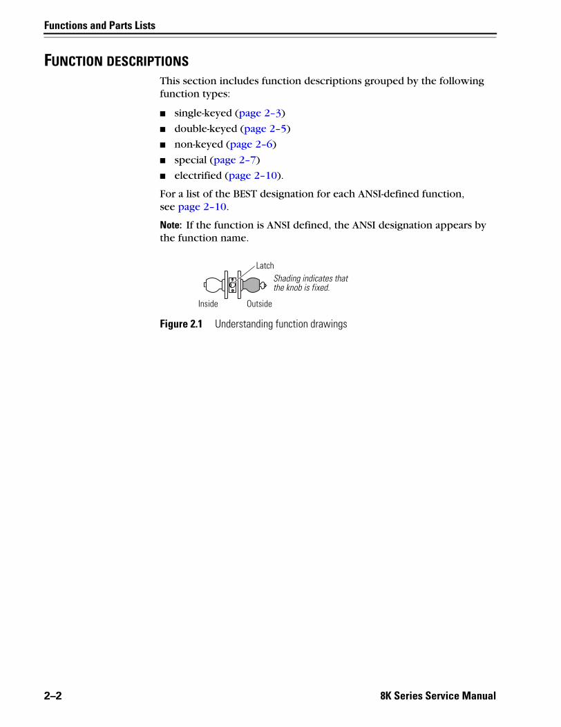
FUNCTION DESCRIPTIONSThis section includes function descriptions grouped by the following function types:
■ single-keyed (page 2–3)
■ double-keyed (page 2–5)
■ non-keyed (page 2–6)
■ special (page 2–7)
■ electrified (page 2–10).
For a list of the BEST designation for each ANSI-defined function, see page 2–10.
Note: If the function is ANSI defined, the ANSI designation appears by the function name.
Figure 2.1 Understanding function drawings
OutsideInside
LatchShading indicates that the knob is fixed.
2–2 8K Series Service Manual

Functions and Parts Lists
Single-keyedfunctions
The following lists describe how the latchbolt, outside knob, and inside knob operate for each single-keyed 8K function.
AB–Entrance (ANSI F109) D–Storeroom (ANSI F86)Latchbolt operated by:■ inside knob■ outside key■ outside knob when the inside
button is in the unlocked position
Outside knob locked by:■ inside button when pushed in■ inside button when pushed in
and rotated clockwiseOutside knob unlocked by:■ inside knob when the inside
button is pushed in but not rotated
■ outside key when the inside button is pushed in but not rotated
■ closing the door when the inside button is pushed in but not rotated
Inside knob is always unlocked
Latchbolt operated by:■ inside knob■ outside keyOutside knob is always fixedInside knob is always unlocked
E–Service station (ANSI F92) H and HJ–Hotel guest room (ANSI F93 for H only)Latchbolt operated by:■ inside knob■ outside key■ outside knob when the inside
button is in the unlocked position
Outside knob locked by:■ inside slotted button■ inside slotted button when
pushed in and rotated clockwise
Outside knob unlocked by:■ inside knob■ inside slotted button when
rotated counterclockwise■ outside key■ closing the door when the
inside button is pushed in but not rotated
Inside knob is always unlocked
Latchbolt operated by:■ inside knob■ outside key when the inside
button is in the unlocked position
■ special emergency key after the core is removed with the control key
Outside knob is always fixedKey block feature released by:■ inside knob■ closing the doorInside knob is always unlocked
Note: For the H function, pushing the inside button projects an “Occupied” indicator in the outside knob and blocks all operating keys. For the HJ function, pushing the inside button blocks all operating keys.
8K Series Service Manual 2–3
Functions and Parts Lists
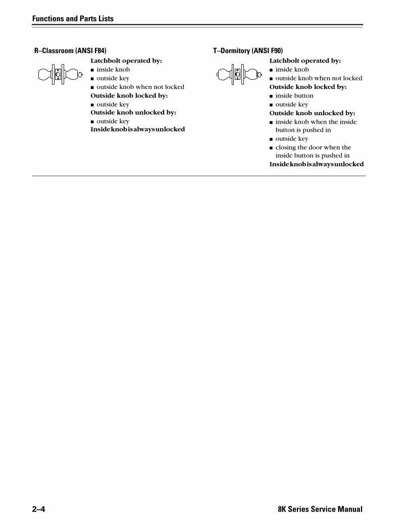
R–Classroom (ANSI F84) T–Dormitory (ANSI F90)Latchbolt operated by:■ inside knob■ outside key■ outside knob when not lockedOutside knob locked by:■ outside keyOutside knob unlocked by:■ outside keyInside knob is always unlocked
Latchbolt operated by:■ inside knob■ outside knob when not locked Outside knob locked by:■ inside button■ outside keyOutside knob unlocked by:■ inside knob when the inside
button is pushed in■ outside key■ closing the door when the
inside button is pushed inInside knob is always unlocked
2–4 8K Series Service Manual

Functions and Parts Lists
Double-keyedfunctions
The following lists describe how the latchbolt, outside knob, and inside knob operate for each double-keyed 8K function.
Warning!
Locks that secure both sides of the door are controlled by building codes and the Life Safety Code®. In an emergency exit situation, failure to quickly unlock the door could be hazardous, or even fatal.
C–Apartment (ANSI F88) G–Storeroom (ANSI F91)Latchbolt operated by:■ inside knob■ outside key■ outside knob when not lockedOutside knob locked by:■ inside keyOutside knob unlocked by:■ inside keyInside knob is always unlocked
Latchbolt operated by:■ inside knob when not locked■ outside knob when not lockedOutside knob locked by:■ inside key■ outside keyOutside knob unlocked by:■ inside key■ outside keyInside knob locked by:■ inside key■ outside keyInside knob unlocked by:■ inside key■ outside key
Note: Turning the key in either the inside or outside knob locks or unlocks both sides.
S–Communicating (ANSI F80) W–Institutional (ANSI F87)Latchbolt operated by:■ inside key■ inside knob when not locked■ outside key■ outside knob when not lockedOutside knob locked by:■ outside keyOutside knob unlocked by:■ outside keyInside knob locked by:■ inside keyInside knob unlocked by:■ inside key
Latchbolt operated by:■ inside key■ outside key Outside knob is always fixedInside knob is always fixed
Note: Turning the key in either knob locks or unlocks that knob independently.
8K Series Service Manual 2–5

Functions and Parts Lists
Non-keyedfunctions
The following lists describe how the latchbolt, outside knob, and inside knob operate for each non-keyed 8K function.
L–Privacy (ANSI F76) N–Passage (ANSI F75)Latchbolt operated by:■ inside knob■ outside knob when the inside
button is in the unlocked position
Outside knob locked by:■ inside buttonOutside knob unlocked by:■ inside knob■ outside slotted button when
pushed in and rotated counterclockwise
■ closing the doorInside knob is always unlocked
Latchbolt operated by:■ inside knob ■ outside knob Outside knob is always unlockedInside knob is always unlocked
NX–Exit (ANSI F89) P–Patio (ANSI F77)Latchbolt operated by:■ inside knobOutside knob is always fixedInside knob is always unlocked
Latchbolt operated by:■ inside knob■ outside knob when the inside
button is in the unlocked position
Outside knob locked by:■ inside buttonOutside knob unlocked by:■ inside knob■ closing the doorInside knob is always unlocked
Y–Exit 1DT–Single dummy trimLatchbolt operated by:■ inside knobInside knob is always unlocked
This assembly is a single, surface mounted knob for an inactive door or a non-latching door. Single dummy trim can be installed on the inside or outside of the door.
2DT–Double dummy trimThis assembly is a through-bolt mounted pair of matching knobs for an inactive door or a non-latching door.
2–6 8K Series Service Manual

Functions and Parts Lists
Specialapplications
The following lists describe how the latchbolt, outside knob, and inside knob operate for each special 8K function.
Warning!
Locks that secure both sides of the door are controlled by building codes and the Life Safety Code®. In an emergency exit situation, failure to quickly unlock the door could be hazardous, or even fatal.
A–Dormitory or storeroom lock (ANSI F81) B–Office (ANSI F82)Latchbolt operated by:■ inside knob■ outside key■ outside knob when the inside
button is in the unlocked position
Outside knob locked by:■ inside buttonOutside knob unlocked by:■ inside buttonInside knob is always unlocked
Latchbolt operated by:■ inside knob■ outside key■ outside knob when the inside
button is in the unlocked position
Outside knob locked by:■ inside buttonOutside knob unlocked by:■ inside knob■ outside keyInside knob is always unlockedNote: Inside button must be rotated
counterclockwise to unlock the outside knob. Note: Inside button is released by turning the key in the outside knob or rotating the inside knob. Closing the door does not release the inside button.
DR–Special DZ–Closet or storeroomLatchbolt operated by:■ inside key■ inside knob when not locked■ outside keyOutside knob is always fixedInside knob locked by:■ inside keyInside knob unlocked by:■ inside key
Latchbolt operated by:■ inside turn knob■ outside keyOutside knob is always fixedInside turn knob is always unlocked
8K Series Service Manual 2–7
Functions and Parts Lists
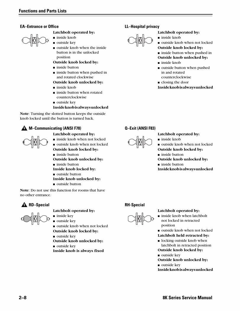
EA–Entrance or Office LL–Hospital privacyLatchbolt operated by:■ inside knob■ outside key■ outside knob when the inside
button is in the unlocked position
Outside knob locked by:■ inside button■ inside button when pushed in
and rotated clockwiseOutside knob unlocked by:■ inside knob■ inside button when rotated
counterclockwise■ outside keyInside knob is always unlocked
Latchbolt operated by:■ inside knob■ outside knob when not lockedOutside knob locked by:■ inside button when pushed inOutside knob unlocked by:■ inside knob■ outside button when pushed
in and rotated counterclockwise
■ closing the doorInside knob is always unlocked
Note: Turning the slotted button keeps the outside knob locked until the button is turned back.
M–Communicating (ANSI F78) Q–Exit (ANSI F83)Latchbolt operated by:■ inside knob when not locked ■ outside knob when not lockedOutside knob locked by:■ inside buttonOutside knob unlocked by:■ inside buttonInside knob locked by:■ outside buttonInside knob unlocked by:■ outside button
Latchbolt operated by:■ inside knob■ outside knob when not lockedOutside knob locked by:■ inside buttonOutside knob unlocked by:■ inside buttonInside knob is always unlocked
Note: Do not use this function for rooms that have no other entrance.
RD–Special RH-SpecialLatchbolt operated by:■ inside key■ outside key■ outside knob when not lockedOutside knob locked by:■ outside keyOutside knob unlocked by:■ outside keyInside knob is always fixed
Latchbolt operated by:■ inside knob when latchbolt
not locked in retracted position
■ outside knob when not lockedLatchbolt held retracted by:■ locking outside knob when
latchbolt in retracted positionOutside knob locked by:■ outside keyOutside knob unlocked by:■ outside keyInside knob is always unlocked
2–8 8K Series Service Manual

Functions and Parts Lists
RZ–Closet or storeroom XD–SpecialLatchbolt operated by:■ inside turn knob■ outside key■ outside knob when not lockedOutside knob locked by:■ outside keyOutside knob unlocked by:■ outside keyInside turn knob is always unlocked
Latchbolt operated by:■ inside keyOutside knob is always fixedInside knob is always fixed
XR–Special YD–ExitLatchbolt operated by:■ inside key■ inside knob when not lockedOutside knob is always fixedInside knob locked by:■ inside keyInside knob unlocked by:■ inside key
Latchbolt operated by:■ inside keyInside knob is always fixed
YR–Special Z–Closet latchLatchbolt operated by:■ inside key■ inside knob when not lockedInside knob locked by:■ inside keyInside knob unlocked by:■ inside key
Latchbolt operated by:■ inside turn knob ■ outside knobOutside knob is always unlockedInside turn blade is always unlocked
8K Series Service Manual 2–9

Functions and Parts Lists
Electrifiedfunctions
The following lists describe how the latchbolt, outside knob, and inside knob operate for each 8K electrified function.
Functionsby ANSI
designation
DEL–Electrically Locked–Fail Safe DEU–Electrically Unlocked–Fail SecureLatchbolt operated by:■ inside knob■ outside knob when electric
power is removed from the solenoid
■ outside keyOutside knob locked by:■ applying 24 VDC to the
solenoid; remains locked only while power continues to be applied
Outside knob unlocked by:■ removing 24 VDC from the
solenoidInside knob is always unlocked
Latchbolt operated by:■ inside knob■ outside knob when electric
power is applied to the solenoid
■ outside keyOutside knob locked by:■ removing 24 VDC from the
solenoidOutside knob unlocked by:■ applying 24 VDC to the
solenoid; remains unlocked only while power continues to be applied
Inside knob is always unlocked
ANSI no. FunctionF75 N
F76 L
F77 P
F78 M
F80 S
F81 A
F82 B
F83 Q
F84 R
F86 D
F87 W
F88 C
F89 NX
F90 T
F91 G
F92 E
F93 H
F109 AB
2–10 8K Series Service Manual
Functions and Parts Lists
8K Series Service Manual
2–11
8
11
Outside
10
AB
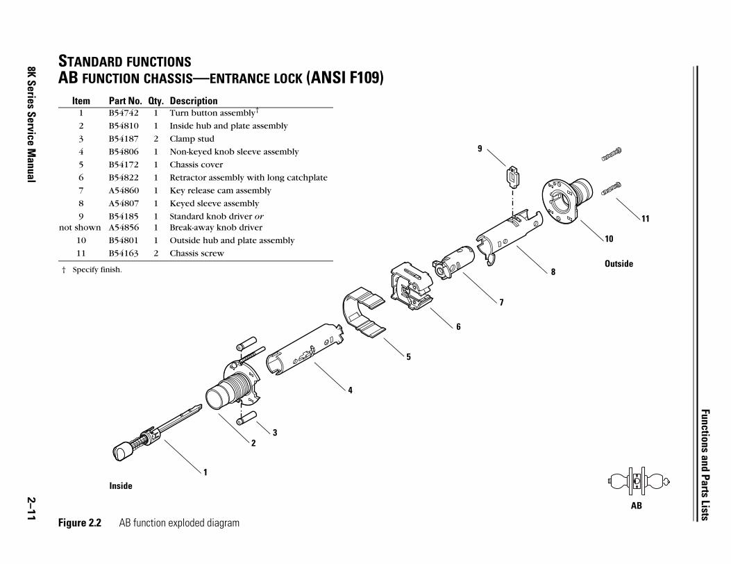
STANDARD FUNCTIONSAB FUNCTION CHASSIS—ENTRANCE LOCK (ANSI F109)
Figure 2.2 AB function exploded diagram
1
32
4
5
6
7
9
Item Part No. Qty. Description1 B54742 1 Turn button assembly†
† Specify finish.
2 B54810 1 Inside hub and plate assembly
3 B54187 2 Clamp stud
4 B54806 1 Non-keyed knob sleeve assembly
5 B54172 1 Chassis cover
6 B54822 1 Retractor assembly with long catchplate
7 A54860 1 Key release cam assembly
8 A54807 1 Keyed sleeve assembly
9not shown
B54185A54856
11
Standard knob driver orBreak-away knob driver
10 B54801 1 Outside hub and plate assembly
11 B54163 2 Chassis screw
Inside

Functions and Parts Lists
2 C FUNCTION CHASSIS—APARTMENT LOCK (ANSI F88)
10
11
Outside
C
–12
8K Series Service Manual Figure 2.3 C function exploded diagram
Item Part No. Qty. Description1 A54810 1 Inside hub and plate assembly
2 B54187 2 Clamp stud
3 B54807 2 Keyed sleeve assembly
4not shown
B54185A54856
22
Standard knob driver orBreak-away knob driver
5 A54863 1 Key release cam assembly
6 B54172 1 Chassis cover
7 A54190 1 Locking bar
8 B54820 1 Retractor assembly without catchplate
9 A54860 1 Key release cam assembly
10 B54801 1 Outside hub and plate assembly
11 B54163 2 Chassis screw
6
5
4
3
9
7
8
12
3
4
Inside

Functions and Parts Lists
8K Series Service Manual
2–13
10
9
Outside
D
D FUNCTION CHASSIS—STOREROOM LOCK (ANSI F86)
Figure 2.4 D function exploded diagram
8
Item Part No. Qty. Description1 A54810 1 Inside hub and plate assembly
2 B54187 2 Clamp stud
3 B54806 1 Non-keyed sleeve assembly
4 B54172 1 Chassis cover
5 B54820 1 Retractor assembly without catchplate
6 A54861 1 Key release cam assembly
7not shown
B54185A54856
11
Standard knob driver orBreak-away knob driver
8 B54807 1 Keyed sleeve assembly
9 B54801 1 Outside hub and plate assembly
10 B54163 2 Chassis screw
3
4
5
6
Inside
7
21
Functions and Parts Lists
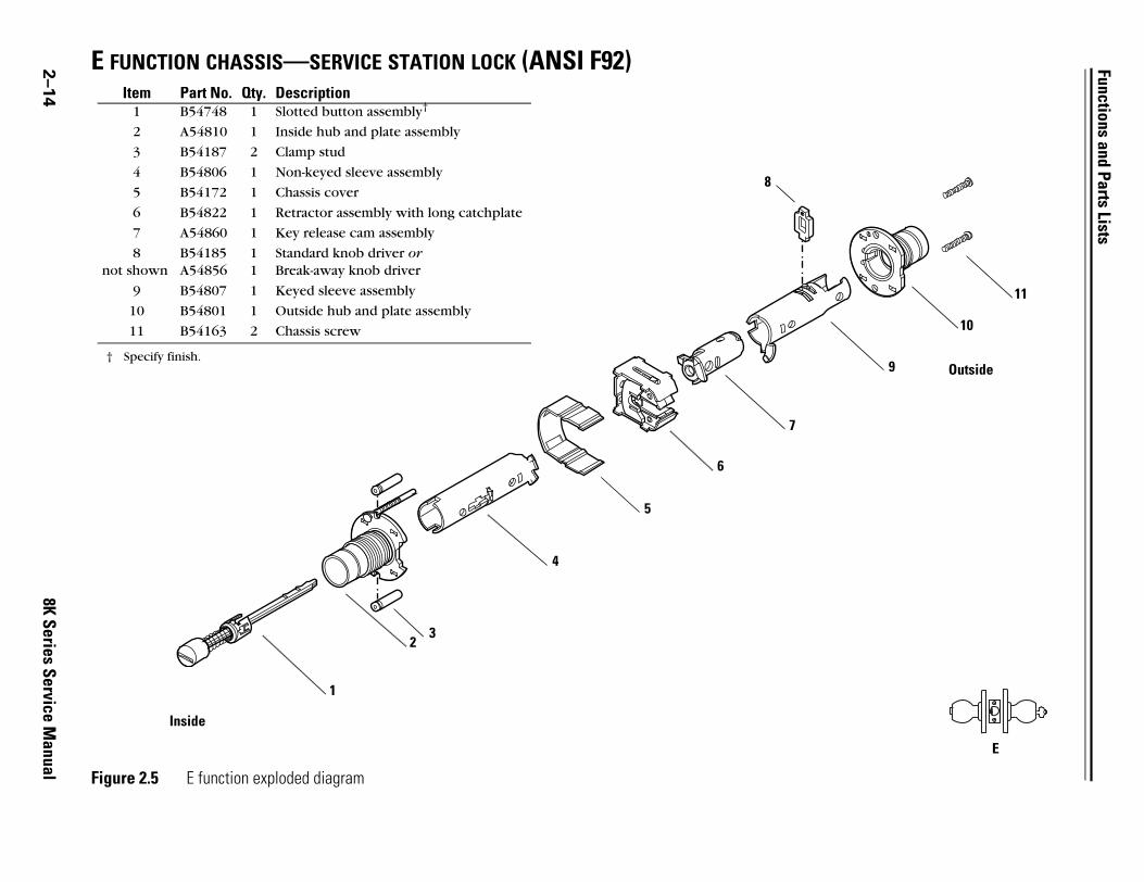
2 E FUNCTION CHASSIS—SERVICE STATION LOCK (ANSI F92)
11
Outside
E
10
9
E
–14
8K Series Service Manual Figure 2.5 E function exploded diagram
8
Item Part No. Qty. Description1 B54748 1 Slotted button assembly†
† Specify finish.
2 A54810 1 Inside hub and plate assembly
3 B54187 2 Clamp stud
4 B54806 1 Non-keyed sleeve assembly
5 B54172 1 Chassis cover
6 B54822 1 Retractor assembly with long catchplate
7 A54860 1 Key release cam assembly
8not shown
B54185A54856
11
Standard knob driver orBreak-away knob driver
9 B54807 1 Keyed sleeve assembly
10 B54801 1 Outside hub and plate assembly
11 B54163 2 Chassis screw
Inside
7
3
4
5
6
2
1

Functions and Parts Lists
8K Series Service Manual
2–15
3
9
Outside
10
G
G FUNCTION CHASSIS—STOREROOM LOCK (ANSI F91)
Figure 2.6 G function exploded diagram
12
3
4
6
7
5
8
5
Item Part No. Qty. Description1 A54810 1 Inside hub and plate assembly
2 B54187 2 Clamp stud
3 B54807 2 Keyed sleeve assembly
4not shown
B54185A54856
22
Standard knob driver orBreak-away knob driver
5 A54864 2 Key release cam assembly
6 B54172 1 Chassis cover
7 B54820 1 Retractor assembly without catchplate
8 A54195 1 Locking bar
9 B54801 1 Outside hub and plate assembly
10 B54163 2 Chassis screw
Inside
4

Functions and Parts Lists
2 H FUNCTION CHASSIS—HOTEL GUEST ROOM LOCK WITH INDICATOR (ANSI F93)
8
9
Outside
H, HJ
–16
8K Series Service Manual
HJ FUNCTION CHASSIS—HOTEL GUEST ROOM LOCK WITHOUT INDICATOR
Figure 2.7 H/HJ function exploded diagram
1
23
4
5
6
7
Item†
† These functions require special throw members. See page 2–55.
Part No. Qty. Description1 B54744 1 Push button assembly‡
‡ Specify finish.
2 B54810 1 Inside hub and plate assembly
3 B54187 2 Clamp stud
4 B54806 1 Non-keyed sleeve assembly
5 B54172 1 Chassis cover
6 B54822 1 Retractor assembly with long catchplate
7 A54865 1 Key release cam assembly
8 B54832 1 Keyed sleeve and hub assembly
9 B54163 2 Chassis screw
Inside

Functions and Parts Lists
8K Series Service Manual
2–17
8
9
11
Outside
L
L FUNCTION CHASSIS—PRIVACY LOCK (ANSI F76)
Figure 2.8 L function exploded diagram
1
23
4
5
6
7
Item Part No. Qty. Description1 B54744 1 Push button assembly†
† Specify finish.
2 A54810 1 Inside hub and plate assembly
3 B54187 2 Clamp stud
4 B54806 1 Non-keyed sleeve assembly
5 B54172 1 Chassis cover
6 B54822 1 Retractor assembly with long catchplate
7 A54860 1 Key release cam assembly
8 B54808 1 Non-keyed sleeve assembly
9 B54801 1 Outside hub and plate assembly
10 A54745 1 Button release assembly†
11 A54163 2 Chassis screw
Inside
10
Functions and Parts Lists
8K Series Service Manual
2–18
7
e
N
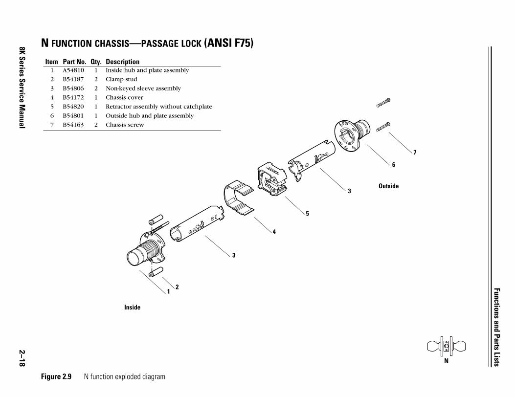
N FUNCTION CHASSIS—PASSAGE LOCK (ANSI F75)
Figure 2.9 N function exploded diagram
12
4
5
3
6
Item Part No. Qty. Description1 A54810 1 Inside hub and plate assembly
2 B54187 2 Clamp stud
3 B54806 2 Non-keyed sleeve assembly
4 B54172 1 Chassis cover
5 B54820 1 Retractor assembly without catchplate
6 B54801 1 Outside hub and plate assembly
7 B54163 2 Chassis screw
Inside
Outsid
3

Functions and Parts Lists
2 NX FUNCTION—EXIT LOCK (ANSI F89)
8
9
Outside
10
NX
–19
8K Series Service Manual
Figure 2.10 NX function exploded diagram
1
23
4
5
6
7
Item Part No. Qty. Description1 B54749 1 Locking bar assembly for NX function†
† Specify finish.
2 B54810 1 Inside hub and plate assembly
3 B54187 2 Clamp stud
4 B54806 1 Non-keyed sleeve assembly
5 B54172 1 Chassis cover
6 B54820 1 Retractor assembly without catchplate
7 A54867 1 Key release cam assembly
8 B54808 1 Non-keyed sleeve assembly
9 B54801 1 Outside hub and plate assembly
10 B54163 2 Chassis screw
Inside

Functions and Parts Lists
8K Series Service Manual
2–20
9
10
Outside
P
P FUNCTION CHASSIS—PATIO LOCK (ANSI F77)
Figure 2.11 P function exploded diagram
1
23
4
5
6
7
8
Item Part No. Qty. Description1 B54744 1 Push button assembly†
† Specify finish.
2 A54810 1 Inside hub and plate assembly
3 B54187 2 Clamp stud
4 B54806 1 Non-keyed sleeve assembly
5 B54172 1 Chassis cover
6 B54822 1 Retractor assembly with long catchplate
7 A54867 1 Key release cam assembly
8 B54808 1 Non-keyed sleeve assembly
9 B54801 1 Outside hub and plate assembly
10 B54163 2 Chassis screw
Inside

Functions and Parts Lists
2 R FUNCTION CHASSIS—CLASSROOM LOCK (ANSI F84)
9
10
Outside
R
–21
8K Series Service Manual
Figure 2.12 R function exploded diagram
12
3
4
5
6
8
7
Item Part No. Qty. Description1 B54810 1 Inside hub and plate assembly
2 B54187 2 Clamp stud
3 B54806 1 Non-keyed sleeve assembly
4 B54172 1 Chassis cover
5 B54820 1 Retractor assembly without catchplate
6 A54862 1 Key release cam assembly
7not shown
B54185A54856
11
Standard knob driver orBreak-away knob driver
8 B54807 1 Keyed sleeve assembly
9 B54801 1 Outside hub and plate assembly
10 B54163 2 Chassis screw
Inside

Functions and Parts Lists
8K Series Service Manual
2–22
9
8
Outside
S
S FUNCTION CHASSIS—COMMUNICATING LOCK (ANSI F80)
Figure 2.13 S function exploded diagram
12
3
6
7
5
5
4
3
Item Part No. Qty. Description1 B54810 1 Inside hub and plate assembly
2 B54187 2 Clamp stud
3 B54807 2 Keyed sleeve assembly
4not shown
B54185A54856
22
Standard knob driver orBreak-away knob driver
5 A54862 2 Key release cam assembly
6 B54172 1 Chassis cover
7 B54820 1 Retractor assembly without catchplate
8 B54801 1 Outside hub and plate assembly
9 B54163 2 Chassis screw
Inside
4
Functions and Parts Lists
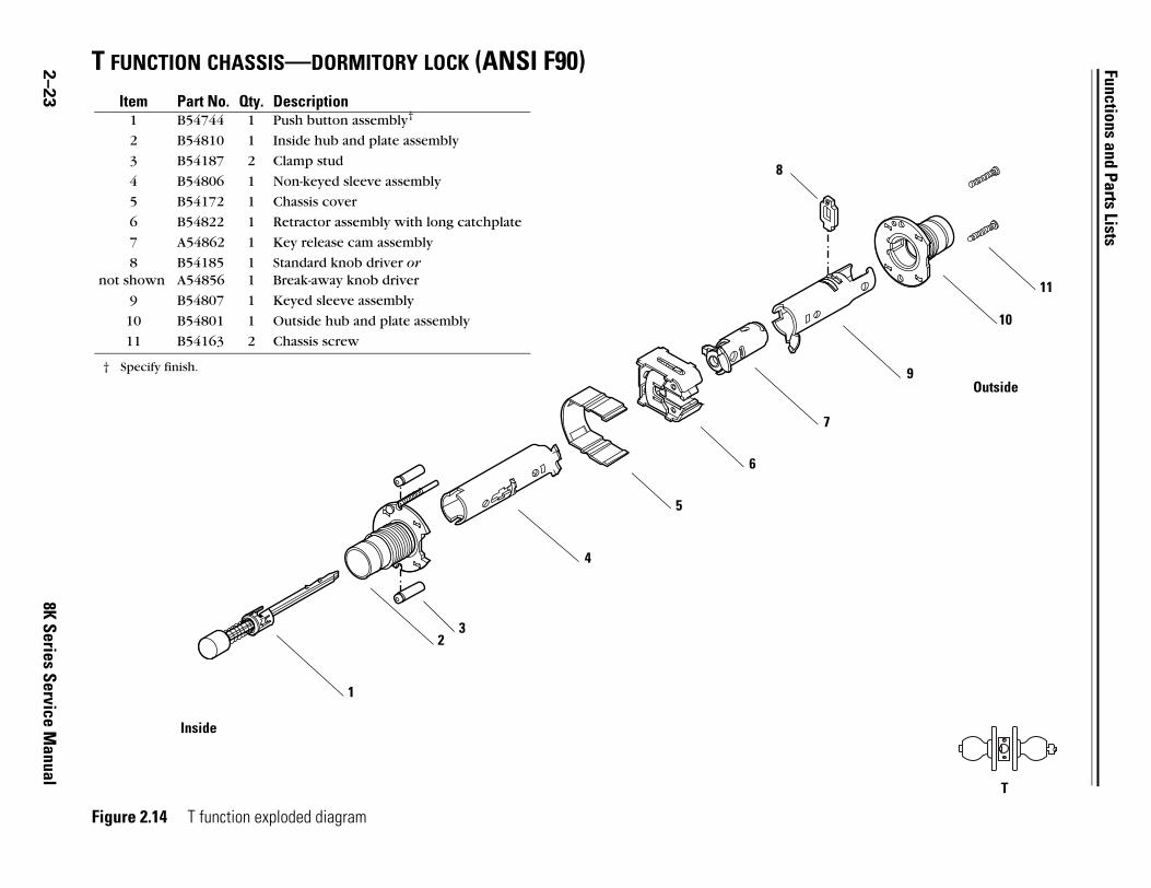
2 T FUNCTION CHASSIS—DORMITORY LOCK (ANSI F90)
9
10
11
Outside
T
–23
8K Series Service Manual
Figure 2.14 T function exploded diagram
1
23
4
5
6
7
8
Item Part No. Qty. Description1 B54744 1 Push button assembly†
† Specify finish.
2 B54810 1 Inside hub and plate assembly
3 B54187 2 Clamp stud
4 B54806 1 Non-keyed sleeve assembly
5 B54172 1 Chassis cover
6 B54822 1 Retractor assembly with long catchplate
7 A54862 1 Key release cam assembly
8not shown
B54185A54856
11
Standard knob driver orBreak-away knob driver
9 B54807 1 Keyed sleeve assembly
10 B54801 1 Outside hub and plate assembly
11 B54163 2 Chassis screw
Inside

Functions and Parts Lists
8K Series Service Manual
2–24
8
9
Outside
W
W FUNCTION CHASSIS—UTILITY OR INSTITUTIONAL LOCK (ANSI F87)
Figure 2.15 W function exploded diagram
12
3
4
6
7
5
3
5
Item Part No. Qty. Description1 B54810 1 Inside hub and plate assembly
2 B54187 2 Clamp stud
3 B54807 2 Keyed sleeve assembly
4not shown
B54185A54856
22
Standard knob driver orBreak-away knob driver
5 A54861 2 Key release cam assembly
6 B54172 1 Chassis cover
7 B54820 1 Retractor assembly without catchplate
8 B54801 1 Outside hub and plate assembly
9 B54163 2 Chassis screw
Inside
4

Functions and Parts Lists
2 Y FUNCTION CHASSIS—EXIT LOCK
7
Outside
Y
8
–25
8K Series Service Manual
Figure 2.16 Y function exploded diagram
12
3
4
5
6
Item Part No. Qty. Description1 B54810 1 Inside hub and plate assembly
2 B54187 2 Clamp stud
3 B54806 1 Non-keyed sleeve assembly
4 B54172 1 Chassis cover
5 B54820 1 Retractor assembly without catchplate
6 B54809 1 Outside hub and plate assembly
7 B54163 2 Chassis screw
8 A54717 1 Outside convex rose for Y function†
† A54717 is the only outside rose available for this function. Specify finish.
Inside

Functions and Parts Lists
8K Series Service Manual
2–26
Outside9
10
A
11
NON-STANDARD FUNCTIONSA FUNCTION CHASSIS—ENTRANCE LOCK (ANSI F81)
Figure 2.17 A function exploded diagram
Item Part No. Qty. Description1 B54742 1 Turn button assembly†
† Specify finish.
2 B54810 1 Inside hub and plate assembly
3 B54187 2 Clamp stud
4 B54806 1 Non-keyed sleeve assembly
5 B54172 1 Chassis cover
6 B54820 1 Retractor assembly without catchplate
7 A54860 1 Key release cam assembly
8not shown
B54185A54856
11
Standard knob driver orBreak-away knob driver
9 B54807 1 Keyed sleeve assembly
10 B54801 1 Outside hub and plate assembly
11 B54163 2 Chassis screw
1
3
4
6
7
8
Inside
2
5

Functions and Parts Lists
2 B FUNCTION CHASSIS—OFFICE LOCK (ANSI F82)
9
10
11
Outside
B
–27
8K Series Service Manual
Figure 2.18 B function exploded diagram
Item Part No. Qty. Description1 B54744 1 Push button assembly†
† Specify finish.
2 B54810 1 Inside hub and plate assembly
3 B54187 2 Clamp stud
4 B54806 1 Non-keyed sleeve assembly
5 B54172 1 Chassis cover
6 B54821 1 Retractor assembly with short catchplate
7 A54860 1 Key release cam assembly
8not shown
B54185A54856
11
Standard knob driver orBreak-away knob driver
9 B54807 1 Keyed sleeve assembly
10 B54801 1 Outside hub and plate assembly
11 B54163 2 Chassis screw
1
3
4
6
7
8
2
5
Inside
Functions and Parts Lists
8K Series Service Manual
2–28
9
10
Outside
DR
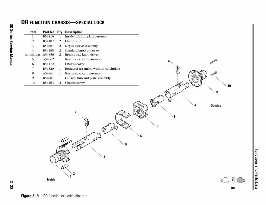
DR FUNCTION CHASSIS—SPECIAL LOCK
Figure 2.19 DR function exploded diagram
Item Part No. Qty. Description1 B54810 1 Inside hub and plate assembly
2 B54187 2 Clamp stud
3 B54807 2 Keyed sleeve assembly
4not shown
B54185A54856
22
Standard knob driver orBreak-away knob driver
5 A54862 1 Key release cam assembly
6 B54172 1 Chassis cover
7 B54820 1 Retractor assembly without catchplate
8 A54861 1 Key release cam assembly
9 B54801 1 Outside hub and plate assembly
10 B54163 2 Chassis screw
3
4
5
7
8
3
2
6
Inside1
4

Functions and Parts Lists
2 DZ FUNCTION CHASSIS—CLOSET OR STOREROOM LOCK
10
11
Outside9
DZ
–29
8K Series Service Manual
Figure 2.20 DZ function exploded diagram
Item Part No. Qty. Description1 A54736 1 Turn blade assembly for “Z” function†
† You need to install an A or C style rose first before installing the turn blade assembly. See page 2–51. Specify finish.
2 B54810 1 Inside hub and plate assembly
3 B54187 2 Clamp stud
4 A54835 1 Non-keyed sleeve assembly
5 B54172 1 Chassis cover
6 B54820 1 Retractor assembly without catchplate
7 A54861 1 Key release cam assembly
8not shown
B54185A54856
11
Standard knob driver orBreak-away knob driver
9 B54807 1 Keyed sleeve assembly
10 B54801 1 Outside hub and plate assembly
11 B54163 2 Chassis screw
4
5
7
8
6
23
Inside
1

Functions and Parts Lists
8K Series Service Manual
2–30
9
10
11
Outside
EA
EA FUNCTION CHASSIS—ENTRANCE OR OFFICE LOCK
Figure 2.21 EA function exploded diagram
Item Part No. Qty. Description1 B54748 1 Slotted button assembly†
† Specify finish.
2 B54810 1 Inside hub and plate assembly
3 B54187 2 Clamp stud
4 B54806 1 Non-keyed sleeve assembly
5 B54172 1 Chassis cover
6 B54821 1 Retractor assembly with short catchplate
7 A54860 1 Key release cam assembly
8not shown
B54185A54856
11
Standard knob driver orBreak-away knob driver
9 B54807 1 Keyed sleeve assembly
10 B54801 1 Outside hub and plate assembly
11 B54163 2 Chassis screw
1
3
4
5
6
7
8
2
Inside

Functions and Parts Lists
2 LL FUNCTION CHASSIS—HOSPITAL PRIVACY LOCK
9
11
10
Outside
12
LL
–31
8K Series Service Manual
Figure 2.22 LL function exploded diagram
Item Part No. Qty. Description1 B54744 1 Push button assembly†
† Specify finish.
2 B54810 1 Inside hub and plate assembly
3 B54187 2 Clamp stud
4 B54806 1 Non-keyed sleeve assembly
5 B54172 1 Chassis cover
6 B54822 1 Retractor assembly with long catchplate
7 A54860 1 Key release cam assembly
8not shown
B54185A54856
11
Standard knob driver orBreak-away knob driver
9 B54807 1 Keyed sleeve assembly
10 B54801 1 Outside hub and plate assembly
11 B54742 1 Turn button assembly†
12 B54163 2 Chassis screw
1
3
4
5
6
7
8
2
Inside

Functions and Parts Lists
8K Series Service Manual
2–32
4
9
1
Outside
10
M
M FUNCTION CHASSIS—COMMUNICATING LOCK (ANSI F78)
Figure 2.23 M function exploded diagram
Item Part No. Qty. Description1 B54742 2 Turn button assembly†
† Specify finish.
2 B54810 1 Inside hub and plate assembly
3 B54187 2 Clamp stud
4 B54808 2 Non-keyed sleeve assembly
5 A54866 2 Key release cam assembly
6 B54172 1 Chassis cover
7 A54204 1 Bridge bar
8 B54820 1 Retractor assembly without catchplate
9 B54801 1 Outside hub and plate assembly
10 B54163 2 Chassis screw
1
23
4
5
6
7
5
8
Inside

Functions and Parts Lists
2 Q FUNCTION CHASSIS—EXIT LOCK (ANSI F83)
8
9
10
Outside
Q
–33
8K Series Service Manual
Figure 2.24 Q function exploded diagram
Item Part No. Qty. Description1 B54742 1 Turn button assembly†
† Specify finish.
2 B54810 1 Inside hub and plate assembly
3 B54187 2 Clamp stud
4 B54806 1 Non-keyed sleeve assembly
5 B54172 1 Chassis cover
6 B54820 1 Retractor assembly without catchplate
7 A54867 1 Key release cam assembly
8 B54808 1 Non-keyed sleeve assembly
9 B54801 1 Outside hub and plate assembly
10 B54163 2 Chassis screw
1
3
4
5
6
2
Inside
7

Functions and Parts Lists
8K Series Service Manual
2–34
10
Outside
9
RD
RD FUNCTION CHASSIS—SPECIAL LOCK
Figure 2.25 RD function exploded diagram
Item Part No. Qty. Description1 B54810 1 Inside hub and plate assembly
2 B54187 2 Clamp stud
3 B54807 2 Keyed sleeve assembly
4 A54861 1 Key release cam assembly
5not shown
B54185A54856
22
Standard knob driver orBreak-away knob driver
6 B54172 1 Chassis cover
7 B54820 1 Retractor assembly without catchplate
8 A54862 1 Key release cam assembly
9 B54801 1 Outside hub and plate assembly
10 B54163 2 Chassis screw
3
4
5
6
7
8
5
3
21
Inside
Functions and Parts Lists
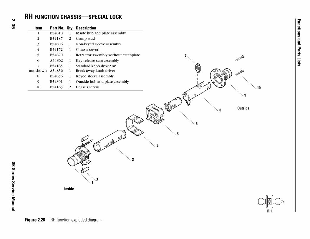
2 RH FUNCTION CHASSIS—SPECIAL LOCK
9
10
Outside
RH
–35
8K Series Service Manual
Figure 2.26 RH function exploded diagram
Item Part No. Qty. Description1 B54810 1 Inside hub and plate assembly
2 B54187 2 Clamp stud
3 B54806 1 Non-keyed sleeve assembly
4 B54172 1 Chassis cover
5 B54820 1 Retractor assembly without catchplate
6 A54862 1 Key release cam assembly
7not shown
B54185A54856
11
Standard knob driver orBreak-away knob driver
8 B54836 1 Keyed sleeve assembly
9 B54801 1 Outside hub and plate assembly
10 B54163 2 Chassis screw
1
3
4
5
6
8
7
2
Inside

Functions and Parts Lists
8K Series Service Manual
2–36
Outside
11
10
RZ
RZ FUNCTION CHASSIS—CLOSET OR STOREROOM LOCK
Figure2.27 RZ function exploded diagram
Item Part No. Qty. Description1 A54736 1 Turn blade assembly for Z function†
† You need to install an A or C style rose first before installing the turn blade assembly. See page 2–51. Specify finish.
2 B54810 1 Inside hub and plate assembly
3 B54187 2 Clamp stud
4 A54835 1 Non-keyed sleeve assembly
5 B54172 1 Chassis cover
6 B54820 1 Retractor assembly without catchplate
7 A54862 1 Key release cam assembly
8not shown
B54185A54856
11
Standard knob driver orBreak-away knob driver
9 B54807 1 Keyed sleeve assembly
10 B54801 1 Outside hub and plate assembly
11 B54163 2 Chassis screw
4
5
6
7
8
9
3
Inside1
2

Functions and Parts Lists
2 XD FUNCTION CHASSIS—SPECIAL LOCK
10
Outside
9
XD
–37
8K Series Service Manual
Figure 2.28 XD function exploded diagram
Item Part No. Qty. Description1 B54810 1 Inside hub and plate assembly
2 B54187 2 Clamp stud
3 B54807 1 Keyed sleeve assembly
4not shown
B54185A54856
11
Standard knob driver orBreak-away knob driver
5 A54861 1 Key release cam assembly
6 B54172 1 Chassis cover
7 B54820 1 Retractor assembly without catchplate
8 B54808 1 Non-keyed sleeve assembly
9 B54801 1 Outside hub and plate assembly
10 B54163 2 Chassis screw
2
3
4
5
6
7
8
1
Inside
Functions and Parts Lists
8K Series Service Manual
2–38
11
10
Outside
XR
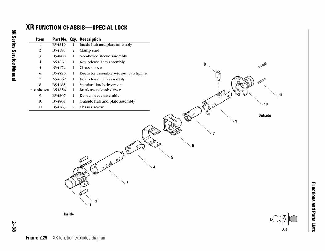
XR FUNCTION CHASSIS—SPECIAL LOCK
Figure 2.29 XR function exploded diagram
Item Part No. Qty. Description1 B54810 1 Inside hub and plate assembly
2 B54187 2 Clamp stud
3 B54808 1 Non-keyed sleeve assembly
4 A54861 1 Key release cam assembly
5 B54172 1 Chassis cover
6 B54820 1 Retractor assembly without catchplate
7 A54862 1 Key release cam assembly
8not shown
B54185A54856
11
Standard knob driver orBreak-away knob driver
9 B54807 1 Keyed sleeve assembly
10 B54801 1 Outside hub and plate assembly
11 B54163 2 Chassis screw
1
3
5
6
7
8
9
2
4
Inside
Functions and Parts Lists
8K Series Service Manual
2–39
8Outside
9
YD
10
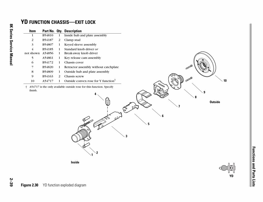
YD FUNCTION CHASSIS—EXIT LOCK
Figure 2.30 YD function exploded diagram
Item Part No. Qty. Description1 B54810 1 Inside hub and plate assembly
2 B54187 2 Clamp stud
3 B54807 1 Keyed sleeve assembly
4not shown
B54185A54856
11
Standard knob driver orBreak-away knob driver
5 A54861 1 Key release cam assembly
6 B54172 1 Chassis cover
7 B54820 1 Retractor assembly without catchplate
8 B54809 1 Outside hub and plate assembly
9 B54163 2 Chassis screw
10 A54717 1 Outside convex rose for Y function†
† A54717 is the only available outside rose for this function. Specify finish.
12
3
4
5
6
7
Inside

Functions and Parts Lists
2 YR FUNCTION CHASSIS—SPECIAL LOCK
8
9
Outside
YR
10
–40
8K Series Service Manual Figure 2.31 YR function exploded diagram
Item Part No. Qty. Description1 B54810 1 Inside hub and plate assembly
2 B54187 2 Clamp stud
3 B54807 1 Keyed sleeve assembly
4not shown
B54185A54856
11
Standard knob driver orBreak-away knob driver
5 A54862 1 Key release cam assembly
6 B54172 1 Chassis cover
7 B54820 1 Retractor assembly without catchplate
8 B54809 1 Outside hub and plate assembly
9 B54163 2 Chassis screw
10 A54717 1 Outside rose for Y function†
† A54717 is the only available outside rose for this function. Specify finish.
12
3
5
7
4
6
Inside
Functions and Parts Lists
8K Series Service Manual
2–41
8
9
Outside
Z
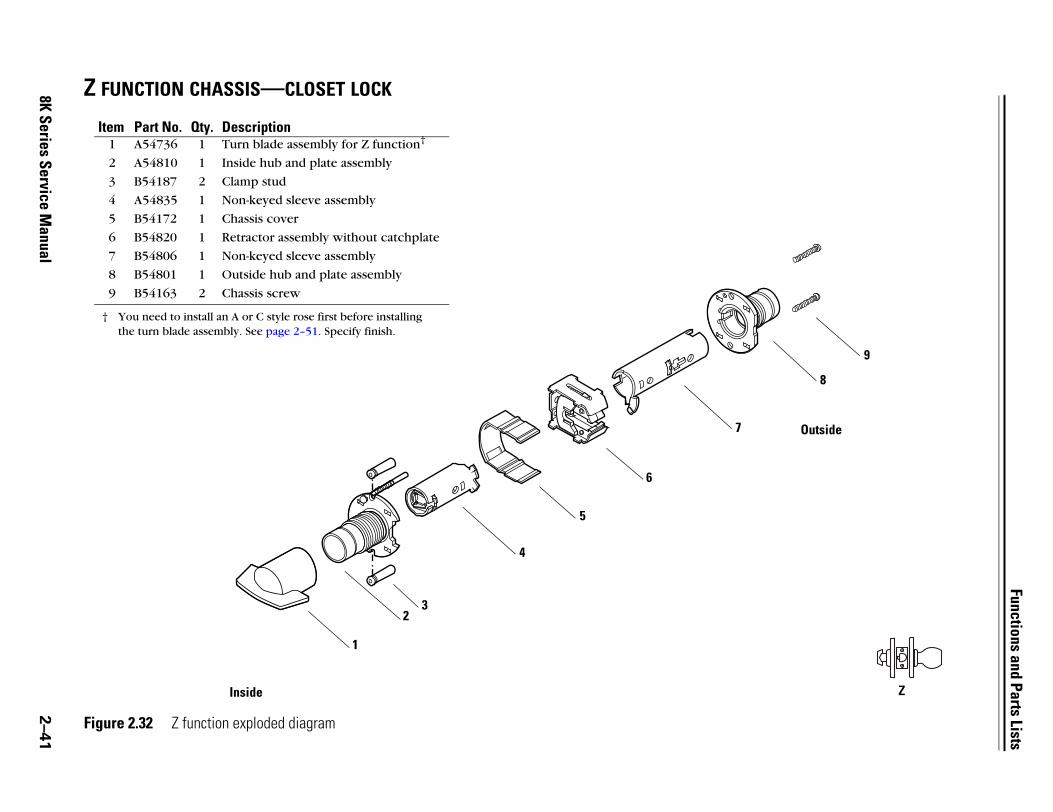
Z FUNCTION CHASSIS—CLOSET LOCK
Figure 2.32 Z function exploded diagram
Item Part No. Qty. Description1 A54736 1 Turn blade assembly for Z function†
† You need to install an A or C style rose first before installing the turn blade assembly. See page 2–51. Specify finish.
2 A54810 1 Inside hub and plate assembly
3 B54187 2 Clamp stud
4 A54835 1 Non-keyed sleeve assembly
5 B54172 1 Chassis cover
6 B54820 1 Retractor assembly without catchplate
7 B54806 1 Non-keyed sleeve assembly
8 B54801 1 Outside hub and plate assembly
9 B54163 2 Chassis screw
23
4
5
6
7
Inside
1

Functions and Parts Lists
2 ELECTRIFIED FUNCTIONS
DEL
DEU
5
13
124
14
15Outside
–42
8K Series Service Manual
DEL FUNCTION CHASSIS—ELECTRICALLY LOCKED FAIL SAFE
Figure 2.33 DEL function exploded diagram
2
6
3
45
7
9
10
11
8
Inside
1

Functions and Parts Lists
DEL chassisparts list
Refer to Figure 2.33 and the table below to find the part you need.
Item Part no. Qty. Description1 B60207 1 Switch plunger
2 A55685 1 Inside hub assembly or
not shown C60206 1 Inside hub assembly for RQE
3 B60418 1 Modified drive collar & non-keyed sleeve assembly
4 B60420 2 Knob return spring
5 B55504 2 Thrust plate
6 B60470 1 Wire protector cap
7 B54172 1 Chassis cover
not shown A60227 1 ID label (affixed to the chassis cover)
8 C60232 1 Solenoid
9 C60224 1 Solenoid spring
10 B60463 1 Chassis frame and retractor assembly
11 A60541 1 Key release cam assembly
12 C55515 1 Spring drive plate
13 A60424 1 Keyed sleeve assembly
14 D55571 1 Outside hub or
not shown D56003 1 Outside hub, lost motion
15 A55505 2 Chassis screw
8K Series Service Manual 2–43

Functions and Parts Lists
2 DEU FUNCTION CHASSIS—ELECTRICALLY UNLOCKED FAIL SECURE
DEU
5
13
124
14
15Outside
–44
8K Series Service Manual
Figure 2.34 DEU function exploded diagram
2
6
3
45
7
9
10
11
8
Inside
1

Functions and Parts Lists
DEU chassisparts list
Refer to Figure 2.34 and the table below to find the part you need.
Item Part no. Qty. Description1 B60207 1 Switch plunger
2 A55685 1 Inside hub assembly or
not shown C60206 1 Inside hub assembly for RQE
3 B60418 1 Modified drive collar & non-keyed sleeve assembly
4 B60420 2 Knob return spring
5 B55504 2 Thrust plate
6 B60470 1 Wire protector cap
7 B54172 1 Chassis cover
not shown A60227 1 ID label (affixed to the chassis cover)
8 C60231 1 Solenoid
9 C60223 1 Solenoid spring
10 B60463 1 Chassis frame and retractor assembly
11 A60531 1 Key release cam assembly
12 C55515 1 Spring drive plate
13 A60424 1 Keyed sleeve assembly
14 D55571 1 Outside hub or
not shown D56003 1 Outside hub, lost motion
15 A55505 2 Chassis screw
8K Series Service Manual 2–45
Functions and Parts Lists
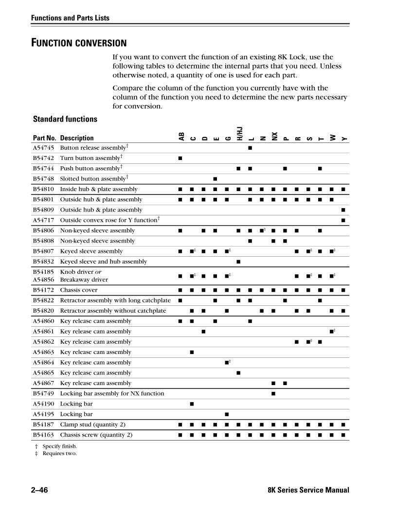
FUNCTION CONVERSIONIf you want to convert the function of an existing 8K Lock, use the following tables to determine the internal parts that you need. Unless otherwise noted, a quantity of one is used for each part.
Compare the column of the function you currently have with the column of the function you need to determine the new parts necessary for conversion.
Standard functions
Part No. Description AB
C D E G H/H
J
L N NX
P R S T W Y
A54745 Button release assembly†■
B54742 Turn button assembly†■
B54744 Push button assembly†■ ■ ■ ■
B54748 Slotted button assembly†■
B54810 Inside hub & plate assembly ■ ■ ■ ■ ■ ■ ■ ■ ■ ■ ■ ■ ■ ■ ■
B54801 Outside hub & plate assembly ■ ■ ■ ■ ■ ■ ■ ■ ■ ■ ■ ■ ■
B54809 Outside hub & plate assembly ■
A54717 Outside convex rose for Y function†■
B54806 Non-keyed sleeve assembly ■ ■ ■ ■ ■ ■‡ ■ ■ ■ ■
B54808 Non-keyed sleeve assembly ■ ■ ■
B54807 Keyed sleeve assembly ■ ■‡ ■ ■ ■‡ ■ ■‡ ■ ■‡
B54832 Keyed sleeve and hub assembly ■
B54185A54856
Knob driver orBreakaway driver
■ ■‡ ■ ■ ■‡ ■ ■‡ ■ ■‡
B54172 Chassis cover ■ ■ ■ ■ ■ ■ ■ ■ ■ ■ ■ ■ ■ ■ ■
B54822 Retractor assembly with long catchplate ■ ■ ■ ■ ■ ■
B54820 Retractor assembly without catchplate ■ ■ ■ ■ ■ ■ ■ ■ ■
A54860 Key release cam assembly ■ ■ ■ ■
A54861 Key release cam assembly ■ ■‡
A54862 Key release cam assembly ■ ■‡ ■
A54863 Key release cam assembly ■
A54864 Key release cam assembly ■‡
A54865 Key release cam assembly ■
A54867 Key release cam assembly ■ ■
B54749 Locking bar assembly for NX function ■
A54190 Locking bar ■
A54195 Locking bar ■
B54187 Clamp stud (quantity 2) ■ ■ ■ ■ ■ ■ ■ ■ ■ ■ ■ ■ ■ ■ ■
B54163 Chassis screw (quantity 2) ■ ■ ■ ■ ■ ■ ■ ■ ■ ■ ■ ■ ■ ■ ■
† Specify finish.‡ Requires two.
2–46 8K Series Service Manual

Functions and Parts Lists
Z
Non-standard functionsPart No. Description A B DR DZ EA LL M Q RD RH RZ XD XR YD YR
A54736 Turn blade assembly for Z function†■ ■ ■
B54742 Turn button assembly†■ ■ ■‡ ■
B54744 Push button assembly†■ ■
B54748 Slotted button assembly†■
B54810 Inside hub and side plate assembly ■ ■ ■ ■ ■ ■ ■ ■ ■ ■ ■ ■ ■ ■ ■ ■
B54801 Outside hub & plate assembly ■ ■ ■ ■ ■ ■ ■ ■ ■ ■ ■ ■ ■ ■
B54809 Outside hub & plate assembly ■ ■
A54717 Outside convex rose for Y function†■ ■
B54806 Non-keyed sleeve assembly ■ ■ ■ ■ ■ ■ ■
B54808 Non-keyed sleeve assembly ■‡ ■ ■ ■
A54835 Non-keyed sleeve assembly ■ ■ ■
B54836 Keyed sleeve assembly ■
B54807 Keyed sleeve assembly ■ ■ ■‡ ■ ■ ■ ■‡ ■ ■ ■ ■
B54185A54856
Knob driver orBreakaway driver
■ ■ ■‡ ■ ■ ■ ■‡ ■ ■ ■ ■ ■ ■
B54172 Chassis cover ■ ■ ■ ■ ■ ■ ■ ■ ■ ■ ■ ■ ■ ■ ■ ■
A54204 Bridge bar ■
B54820 Retractor assembly without catchplate ■ ■ ■ ■ ■ ■ ■ ■ ■ ■ ■ ■ ■
B54821 Retractor assembly with short catchplate ■ ■
B54822 Retractor assembly long catchplate ■
A54860 Key release cam assembly ■ ■ ■ ■
A54861 Key release cam assembly ■ ■ ■ ■ ■
A54862 Key release cam assembly ■ ■ ■ ■ ■ ■
A54866 Key release cam assembly ■‡
A54867 Key release cam assembly ■
B54187 Clamp stud (quantity 2) ■ ■ ■ ■ ■ ■ ■ ■ ■ ■ ■ ■ ■ ■ ■ ■
B54163 Chassis screw (quantity 2) ■ ■ ■ ■ ■ ■ ■ ■ ■ ■ ■ ■ ■ ■ ■ ■
† Specify finish.‡ Requires two.
8K Series Service Manual 2–47

Functions and Parts Lists
Electrical functions
Part No. Description DEL
DEU
B60207 Switch plunger ■ ■
A55685 Inside hub assembly or ■ ■
C60206 Inside hub assembly for RQE ■ ■
B60418 Modified drive collar & non-keyed sleeve assembly ■ ■
B60420 Knob return spring ■ ■
B55504 Thrust plate†
† Requires two.
■ ■
B60470 Wire protector cap ■ ■
B54172 Chassis cover ■ ■
A60227 ID label (affixed to the chassis cover) ■ ■
C60232 Solenoid ■
C60231 Solenoid ■
C60224 Solenoid spring ■
C60223 Solenoid spring ■
B60463 Chassis frame and retractor assembly ■ ■
A60541 Key release cam assembly ■
A60531 Key release cam assembly ■
C55515 Spring drive plate ■ ■
A60424 Keyed sleeve assembly ■ ■
D55571 Outside hub or ■ ■
D56003 Outside hub, lost motion ■ ■
A55505 Chassis screw†■ ■
2–48 8K Series Service Manual

Functions and Parts Lists
TRIM PARTS
Standard strikesand strike boxes
Standard strikes and strike boxes parts list
Non-standardstrikes
Non-standard strikes parts list
Figure 2.35 Standard strikes and strike boxes
1
2
4
3
5
ItemNomen–clature Part no. Description
1 30HS4 B34380 ANSI Plastic strike box
2 8KS3†
† Use the nomenclature to order the ANSI strike package, which includes the strike, two A25359 screws, and two A18724 screws. Specify finish.
B25641 ANSI Strike
3 8KS3-7/8† C63016 ANSI 7/8″ flat lip strike
4 8KS1 B25640 Standard steel strike box
5 8KS2‡
‡ Use the nomenclature to order the standard strike package, which includes the strike and four A25359 screws. Specify finish.
B25639 Standard strike package
Figure 2.36 Understanding strike lip measurement
The measurement is taken from the edge of the lip to the center of the screw holes.
Part no.† X dimensionB54063 7/8″B54064 1 ″B54065 1 1/8″B54066 1 1/2″B54067 1 3/4″B54068 2″B54069 2 1/4″B54070 2 1/2″B54071 3″B54072 4″
† Specify finish.
x
2 34
8K Series Service Manual 2–49
Functions and Parts Lists
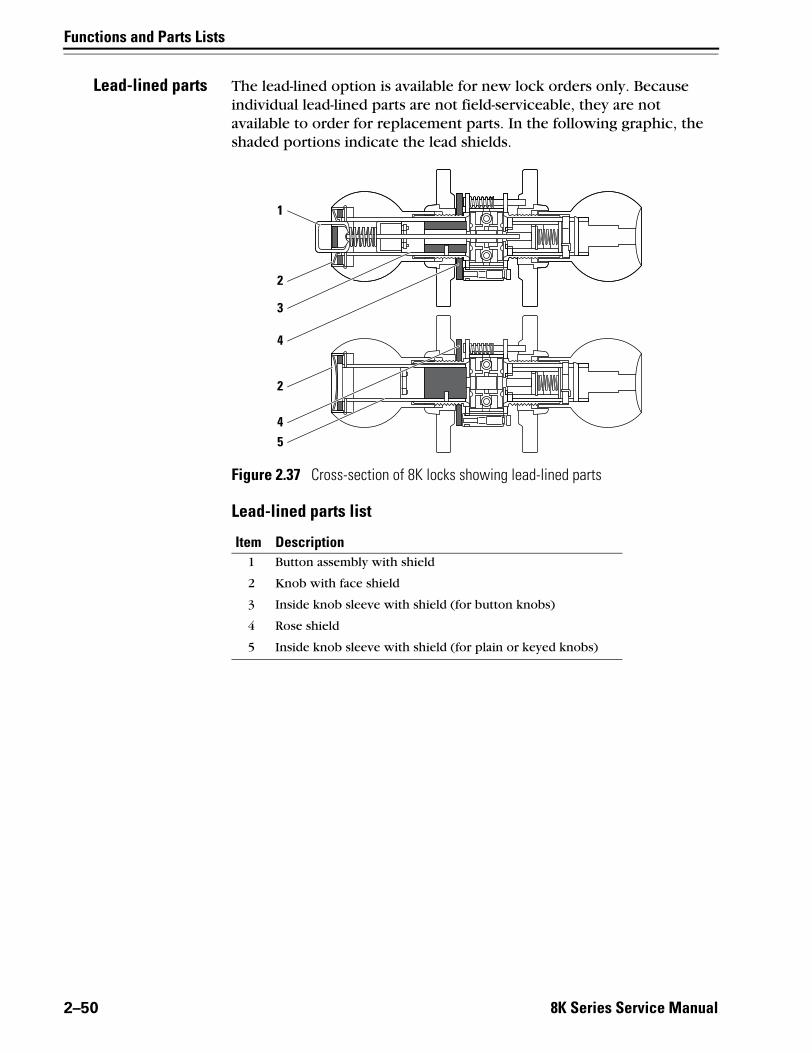
Lead-lined parts The lead-lined option is available for new lock orders only. Because individual lead-lined parts are not field-serviceable, they are not available to order for replacement parts. In the following graphic, the shaded portions indicate the lead shields.
Lead-lined parts list
Figure 2.37 Cross-section of 8K locks showing lead-lined parts
1
2
3
4
2
45
Item Description1 Button assembly with shield
2 Knob with face shield
3 Inside knob sleeve with shield (for button knobs)
4 Rose shield
5 Inside knob sleeve with shield (for plain or keyed knobs)
2–50 8K Series Service Manual

Functions and Parts Lists
Roses androse rings
Roses and rose rings parts list
Figure 2.38 Roses and rose rings
3
2
1
3
5
4
10
96
7
Style A Style C
Style D Style E
8
Item Style Part no. Qty. Description1 A B54702 1 Outside rose assembly—large concave2 A B54700 1 Inside rose assembly—large concave3 A & C A54720 1 Inside rose ring—large concave4 C B54713 1 Outside rose assembly—small concave5 C B54712 1 Inside rose assembly—small concave6 D A54716 1 Outside rose assembly—small concave7 D B54715 1 Inside rose assembly—large convex8 D A54714 1 Inside rose ring—large convex9 E A54723 1 Outside rose assembly—thin door
10 E A54722 1 Inside rose assembly—thin door
8K Series Service Manual 2–51

Functions and Parts Lists
Roses, rose liners,and rose spacers forelectrified functions
Figure 2.39 Roses, rose liners, and rose spacers
Style C
Small spacer Large spacer
Style K
Style D
Style L
1
3
2
4
1
5
3
2
4
5
72
8
9
7
6
102
8
9
10
12
Large RQE rose linerSmall RQE rose liner
1413
2–52 8K Series Service Manual

Functions and Parts Lists
Roses, rose liners, and rose spacers parts list
Rose and rose liner assemblies parts list
Item Style Part no. Description1 C B55015†
† Inside and outside are the same.
Small rose
2 C, D, K, L A55557 Through-bolt screws
3 C & K C55556 Small inside rose liner
4 C & K B55603 Small outside rose liner
5 K B55018† Small rose
6 C & K B55043‡
‡ Two (2) spacers are required for 1 3/8” thick doors.
Small rose spacer
7 N/A A55711 Y function outside rose assembly
8 D B55007† Large rose
9 D & L C55555 Large inside rose liner
10 D & L B55602 Large outside rose liner
11 L B55017† Large rose
12 D & L B55044‡ Large rose spacer
13 N/A B61049 Small RQE rose liner
14 N/A B60221 Large RQE rose liner
Item Style Part no. Description1 & 3 C B55609 Small inside rose and liner assembly
1 & 4 C B55605 Small outside rose and liner assembly
3 & 5 K B55607 Small inside rose and liner assembly
4 & 5 K B55604 Small outside rose and liner assembly
8 & 9 D B55608 Large inside rose and liner assembly
8 & 10 D B55601 Large outside rose and liner assembly
9 & 11 L B55606 Large inside rose and liner assembly
10 & 11 L B55600 Large outside rose and liner assembly
8K Series Service Manual 2–53

Functions and Parts Lists
Knobs and components
Knobs parts list
Figure 2.40 Knobs
1
2
3
4
5
6
7
8
9
Knob style #6 Knob style #4 Lever style #9
Style Item Description Standard Tactile Knurled1 Plain tulip knob B54705 N/A B54756
6 2 Button tulip knob B54706 N/A B54757
3 Keyed tulip knob B54703 N/A B54755
4 Plain round knob B54707 B54731 N/A
4 5 Button round knob B54708 B54732 N/A
6 Keyed round knob B54704 B54730 N/A
7 Plain lever handle†
† Lever handles are not available for electrified functions.
B54778 N/A N/A
9 8 Button lever handle† B54779 N/A N/A
9 Keyed lever handle† B54777 N/A N/A
2–54 8K Series Service Manual

Functions and Parts Lists
Knob components parts list
Figure 2.41 Standard knob components
1
2
4
3
5
Item Part no. Qty. Description1 A55697 1 “H” throw member
2 A55696 1 “HJ” throw member
3 B54200 1†
† Single-keyed locks require one (1); double-keyed locks require two (2).
Seven pin throw member‡
‡ For information about cores and keys, see the Core and Key Service Manual.
4 1882120 50 Six pin spacer
5 B54182 1 Lever keeper spring
8K Series Service Manual 2–55
Functions and Parts Lists
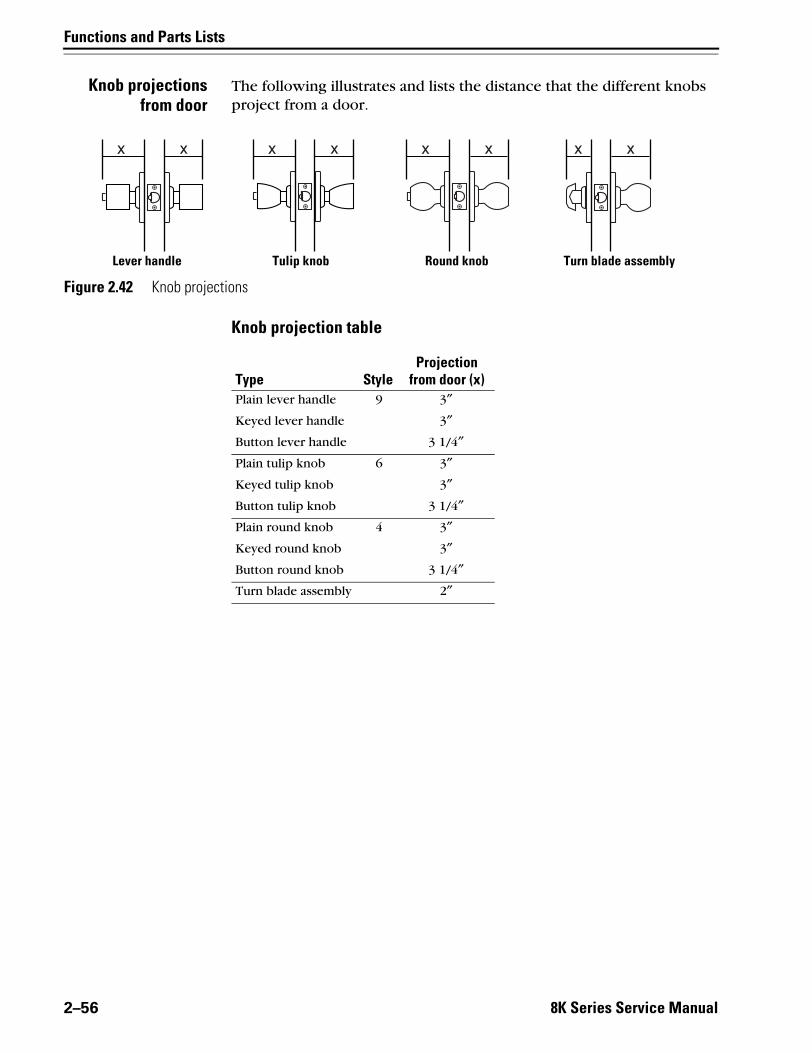
Knob projectionsfrom door
The following illustrates and lists the distance that the different knobs project from a door.
Knob projection table
Figure 2.42 Knob projections
Lever handle Tulip knob Round knob Turn blade assembly
Type StyleProjection
from door (x)Plain lever handle 9 3″Keyed lever handle 3″Button lever handle 3 1/4″Plain tulip knob 6 3″Keyed tulip knob 3″Button tulip knob 3 1/4″Plain round knob 4 3″Keyed round knob 3″Button round knob 3 1/4″Turn blade assembly 2″
2–56 8K Series Service Manual

Functions and Parts Lists
Dummy trim
Single dummy trim parts list
Double dummy trim parts list
Figure 2.43 Dummy trim parts
6
4
51
4
2
3
2
Item Part No. Qty. Description1 B54884 1 Chassis dummy trim assembly
2 A54465 1 “O” ring
3 A39217 2 #8 × 1 PFH type AB screw
4 B55051B55050
11
Small liner and ring assembly orLarge liner and ring assembly
Item Part No. Qty. Description1 B54884 1 Chassis dummy trim assembly
2 A54465 2 “O” ring
4 B55051B55050
22
Small liner and ring assembly orLarge liner and ring assembly
5 B54885 1 Chassis dummy trim assembly
6 A18991 2 #8-32 × 1 1/8 Phil. FHMS screw
8K Series Service Manual 2–57

Functions and Parts Lists
8Wcomponents
8W components parts list
Refer to Figure 2.44 and the table below to find the part you need.
Figure 2.44 8W components
5 76
4321
ItemNomen-clature Description
1 8W599 Transformer
2 8WCON AC to DC converter full wave bridge rectifier
3 8WMOV Metal oxide varistor
4 8WDTL Door transfer loop
5 8WBU-1-A Standard plate for RQE switch
6 8WBU-1-N Narrow plate for RQE switch
7 8WTCM Temperature control module
2–58 8K Series Service Manual

Functions and Parts Lists
Latches
Latches parts list
Figure 2.45 Latches
1 3 4
5 6 7
2
Item Latch type Backset Part no.Nomen-clature†
† Specify finish.
Description1 Deadlocking 2 3/4″ C54680 8KL3‡
‡ Use the nomenclature to order the latch package, which includes the latch and two A25359 screws.
Latch
2 Deadlocking 2 3/4″ A54661 8KL3-3/4‡ Latch with 3/4″ throw
3 Deadlocking 3 3/4″ C54682 8KL4‡ Latch
4 Deadlocking 5″ C54684 8KL5‡ Latch
5 Spring 2 3/4″ C54681 8KSL3‡ Latch
6 Spring 3 3/4″ C54683 8KSL4‡ Latch
7 Spring 5″ C54685 8KSL5‡ Latch
8K Series Service Manual 2–59

Functions and Parts Lists
Installation tools
Installation tools parts list
Figure 2.46 Installation tools
1
54
2 3
ItemNomen-clature Part no. Description
1 KD325 A01514 Strike plate locating pin
2not shown
KD315KD312
13503931487975
Faceplate marking chisel (1 1/8″ × 2 1/4″ )Faceplate marking chisel (1″ × 2 1/4″ )
3 KD316 C54466 KD316 spanner wrench
4 KD309 A54084 2 1/8″ diameter chassis hole bit assembly†
† Use with the boring jig.
5 KD318 A54085 1″ diameter drill bit assembly†
2–60 8K Series Service Manual

Functions and Parts Lists
Boring jig kit parts list
Figure 2.47 Boring jig kit
1
4
56
3
2
ItemNomen-clature Part no. Description
1 N/A N/A Boring jig†
2 KD325 A01514 Strike plate locating pin
3 KD315 1350393 Faceplate marking chisel (1 1/8″ × 2 1/4″ )
not shown KD312 1487975 Faceplate marking chisel (1″ × 2 1/4″ )4 KD309 A54084 2 1/8″ diameter chassis hole bit assembly
5 KD318 A54085 1″ diameter drill bit assembly
6 N/A N/A Adaptor for 3/8″ drill chuck†
† Can only be ordered as part of the KD304A boring jig kit.
1–6 KD304A N/A Boring jig kit
8K Series Service Manual 2–61

Functions and Parts Lists
2–62 8K Series Service Manual
3
8K Series Service
SERVICE AND MAINTENANCE
This chapter contains instructions for replacing components, servicing and maintaining components, and troubleshooting common problems.
ToSee page
Replace knobs 3–3
Replace the knob driver 3–6
Replace roses 3–7
Replace button assemblies 3–10
Replace the knob keeper spring 3–12
Replace the key release cam assembly 3–13
Replace the sleeve assembly 3–16
Replace electrified function roses 3–18
Replace the RQE rose liner 3–21
Replace the solenoid 3–21
Add the RQE switch to a function 3–22
Reverse the solenoid when changing functions 3–22
Lubricate cores 3–22
Align chassis and trim 3–23
Position the locking cam for C function locks 3–24
Position the locking cam for G function locks 3–25
Position the locking cam for R, S, & T function locks 3–26
Use the emergency key for H and HJ function locks 3–28
Troubleshoot common problems 3–29
Manual 3–1

Service and Maintenance
MAINTENANCE TOOLS
Maintenancetools parts list
Figure 3.1 Maintenance tools
1
2 3
ItemNomen-clature Part no. Description
1 KD316 C54466 KD316 spanner wrench
2 KD317 C55506 KD317 spanner wrench
3 A25586 Emergency driver†
† For use with hotel function locks (H and HJ).
3–2 8K Series Service Manual

Service and Maintenance
REPLACING COMPONENTS
Replacing theknob
To remove the keyed knob:1. Insert the control key into the core and rotate the key 15 degrees to
the right.
2. Remove the core and throw member from the knob.
3. Insert a flat blade screwdriver into the figure-8 core hole and into the knob keeper.
4. Press the screwdriver blade in the direction of the arrow, as shown in Figure 3.2.
Note: You will not be able to remove the knob if the screwdriver blade is inserted too far past the keeper.
5. Slide the knob off of the sleeve.
Figure 3.2 Removing the keyed knob
Insert the screwdriver here.
Knob keeper
Figure-8 core hole
8K Series Service Manual 3–3

Service and Maintenance
To remove the plain knob or button knob:1. Insert the long protrusion on the KD316 spanner wrench into the
hole on the shaft of the knob, as shown in Figure 3.3.
2. Slide the knob off the sleeve.
To reinstall the knob:1. Align the two drive lugs (plain or button knob) or notches (keyed
knob) with the two slots in the sleeve, as shown in Figure 3.4.
2. Slide the knob onto the sleeve and firmly push on the knob until it is seated.
Figure 3.3 Removing the plain knob or button knob
Long protrusion on the KD316 spanner wrench
Knob shaft
Inside of LH door
3–4 8K Series Service Manual
Service and Maintenance
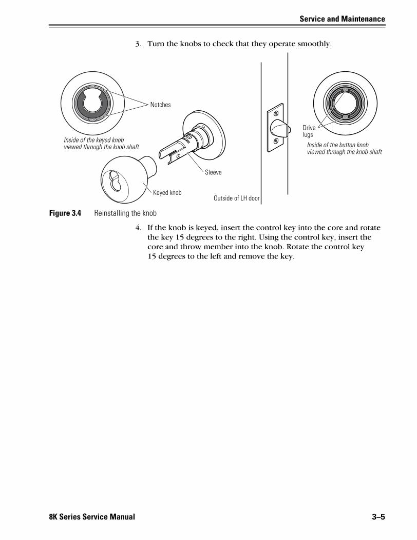
3. Turn the knobs to check that they operate smoothly.
4. If the knob is keyed, insert the control key into the core and rotate the key 15 degrees to the right. Using the control key, insert the core and throw member into the knob. Rotate the control key 15 degrees to the left and remove the key.
Figure 3.4 Reinstalling the knob
Sleeve
Notches
Inside of the keyed knob viewed through the knob shaft
Outside of LH doorKeyed knob
Drive lugs
Inside of the button knob viewed through the knob shaft
8K Series Service Manual 3–5

Service and Maintenance
Replacing theknob driver
To remove the knob driver:1. Remove the keyed knob (page 3–3).
2. Use a flat blade screwdriver to press down on the knob driver tab, which is visible through the cutout in the top of the sleeve, as shown in Figure 3.5. The knob driver should fall out through the cutout in the bottom of the sleeve.
To reinstall the knob driver:1. Position the knob driver as shown in Figure 3.6.
2. Insert the knob driver into the sleeve until it snaps into place. The knob driver tab should be visible through the cutout in the top of the sleeve.
Figure 3.5 Removing the knob driver
Press with the screwdriver here.
Outside of door
Knob driver tab
3–6 8K Series Service Manual

Service and Maintenance
3. Reinstall the keyed knob (page 3–4).
Replacing theinside rose
assembly
To remove the inside rose assembly:1. Remove the inside knob (page 3–4).
2. Insert the short protrusion on the KD316 spanner wrench into the hole on the rose ring and rotate it until you can remove the rose ring, as shown in Figure 3.7.
3. Slide the rose assembly off of the sleeve.
Figure 3.6 Reinstalling the knob driver
Outside of door
Knob driver
Cutout in sleeve
Figure 3.7 Removing the inside rose ring with the KD316 spanner wrench
Inside of door
Short protrusion on the KD316 spanner wrench
Rose ring
8K Series Service Manual 3–7

Service and Maintenance
To reinstall the inside rose assembly:1. Slide the rose assembly onto the sleeve, as shown in Figure 3.8.
2. Thread the rose ring onto the sleeve until the rose assembly is snug against the door.
3. Reinstall the knob (page 3–4).
Replacing theoutside rose
assembly
To remove the outside rose assembly:1. Remove the following components:
■ knobs (page 3–3)
■ inside rose assembly (page 3–7).
2. Slide the chassis assembly out of the door.
3. Retract the rose locking pin, and rotate the rose assembly until it is free from the hub. See Figure 3.9.
Figure 3.8 Reinstalling the inside rose assembly and rose ring
Inside of door
Inside sleeve
Rose assembly
Rose ring
3–8 8K Series Service Manual

Service and Maintenance
4. Remove the outside rose assembly from the sleeve.
To reinstall the outside rose assembly:1. Retract the rose locking pin. See Figure 3.10. When reinstalling the
chassis and rose assembly in the door, rotate the rose assembly until it is positioned so that the chassis is centered in the door and the rose assembly is flush against the door.
2. Release the rose locking pin into a groove in the rose liner. The pin should lock into the rose liner.
Figure 3.9 Removing the outside rose assembly
Rose assembly
Outside sleeveRose locking pin
Inside sleeve
Figure 3.10 Reinstalling the outside rose assembly
Rose assembly
Outside sleeveRose locking pin
Inside sleeve
8K Series Service Manual 3–9
Service and Maintenance
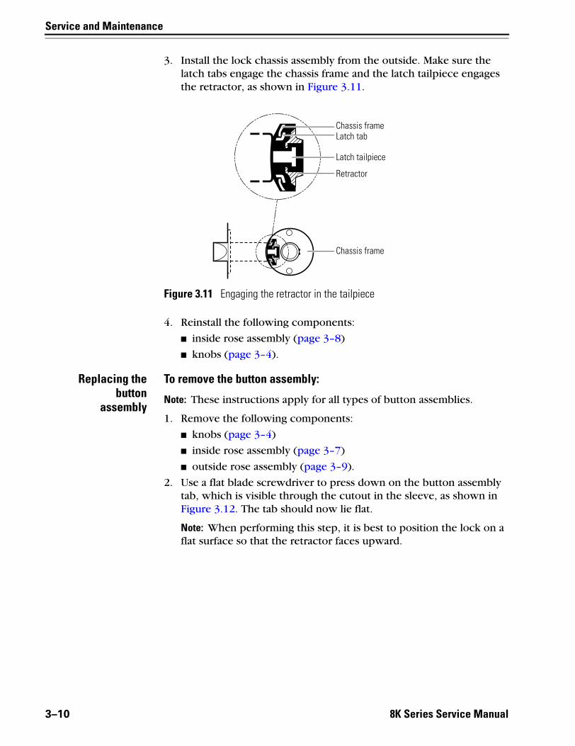
3. Install the lock chassis assembly from the outside. Make sure the latch tabs engage the chassis frame and the latch tailpiece engages the retractor, as shown in Figure 3.11.
4. Reinstall the following components:
■ inside rose assembly (page 3–8)
■ knobs (page 3–4).
Replacing thebutton
assembly
To remove the button assembly:
Note: These instructions apply for all types of button assemblies.
1. Remove the following components:
■ knobs (page 3–4)
■ inside rose assembly (page 3–7)
■ outside rose assembly (page 3–9).
2. Use a flat blade screwdriver to press down on the button assembly tab, which is visible through the cutout in the sleeve, as shown inFigure 3.12. The tab should now lie flat.
Note: When performing this step, it is best to position the lock on a flat surface so that the retractor faces upward.
Figure 3.11 Engaging the retractor in the tailpiece
Chassis frameLatch tab
Latch tailpiece
Retractor
Chassis frame
3–10 8K Series Service Manual

Service and Maintenance
3. Press down on the retractor and slide the button assembly out of the sleeve.
To reinstall the button assembly:1. Insert the new button assembly into the sleeve, as shown in
Figure 3.13, until the tab lines up with the cutout in the sleeve. It may be necessary to slightly press in the retractor with your thumb so that the locking bar can properly align itself through the chassis and into the key release cam assembly.
Note: The button assembly should not pop out of the sleeve. If it does, the assembly is misaligned and will not function properly.
Figure 3.12 Removing the button assembly
Retractor
Sleeve
Button assembly tab
Figure 3.13 Inserting the button assembly into the sleeve
Locking bar
Cutout in sleeve
Button assembly tab
Retractor
8K Series Service Manual 3–11

Service and Maintenance
2. Insert a small screwdriver into the cutout in the sleeve and under the button assembly tab. Bend the tab into the cutout, as shown in Figure 3.14.
Note: Do not bend the tab so that it protrudes further than the diameter of the sleeve. It could interfere with the knob function.
3. Reinstall the following components:
■ outside rose assembly (page 3–9)
■ inside rose assembly (page 3–7)
■ knobs (page 3–4).
Replacing theknob keeper
spring
To remove the knob keeper spring:1. Remove the following components:
■ knobs (page 3–4)
■ inside rose assembly (page 3–7)
■ outside rose assembly (page 3–8)
■ button assembly, if present (page 3–10).
2. Using a pair of needle-nosed pliers, reach into the sleeve and remove the knob keeper spring. See Figure 3.15.
Figure 3.14 Bending the button assembly tab
Sleeve
Button assembly tab
Figure 3.15 Removing the knob keeper spring
Knob keeper spring
Knob keeper
Head-on view of the knob keeper inside the sleeve
3–12 8K Series Service Manual

Service and Maintenance
To reinstall the knob keeper spring:1. Position the knob keeper spring as shown in Figure 3.16.
2. Use a pair of needle-nosed pliers to insert the knob keeper spring into the sleeve. Using the pliers, work the spring into position so that the spring is gripping the knob keeper, as shown in Figure 3.17.
Note: If the knob keeper spring is not installed correctly, the knob may fall off the chassis.
3. Reinstall the following components:
■ button assembly, if present (page 3–11)
■ outside rose assembly (page 3–9)
■ inside rose assembly (page 3–7)
■ knobs (page 3–4).
Replacing thekey release
cam assembly
To remove the key release cam assembly:1. Remove the following components:
■ knobs (page 3–4)
■ inside rose assembly (page 3–7)
■ outside rose assembly (page 3–8)
■ button assembly, if present (page 3–10).
Figure 3.16 Positioning the knob keeper spring
Knob keeper spring
Outside sleeve assembly
Figure 3.17 Knob return spring in position
Knob keeper spring
Knob keeper
Head-on view of the knob keeper inside the sleeve
8K Series Service Manual 3–13

Service and Maintenance
2. Remove the two chassis screws shown in Figure 3.18, and separate the hub and sleeve assembly from the rest of the chassis. Save the two screws.
3. Rotate the ear on the key release cam 45 degrees and pull the key release cam assembly out of the sleeve, as shown in Figure 3.19.
To reinstall the key release cam assembly:1. Make sure that the deep slot in the sleeve lines up with the slot in
the hub.
2. Insert the key release cam assembly into the sleeve so that the locking lug fits into the slot in the sleeve, as shown in Figure 3.20.
Figure 3.18 Separating the chassis
Chassis screws
Keyed sleeve assembly
Hub
Figure 3.19 Removing the key release cam assembly
Key release cam assembly
Ear in rotated position
Figure 3.20 Reinstalling the key release cam assembly
Locking lug
Slot in the sleeve
Key release cam assembly
3–14 8K Series Service Manual

Service and Maintenance
3. Slide the chassis cover over the retractor assembly.
4. Align the open end of the retractor assembly with the ears on the key release cam assembly and sleeve in the inside hub assembly.
5. Press the retractor toward the retractor springs and insert the feet of the retractor assembly into the notches in the inside hub, as shown in Figure 3.21.
6. Align the feet of the retractor assembly with the notches in the outside hub assembly, and the rose locking pin with the smaller of the two holes on the outside assembly, as shown in Figure 3.22. Press the retractor toward the retractor springs and slide the two sections together.
7. Install the two chassis screws.
Figure 3.21 Positioning the retractor
Notches in the inside hub
Open end of the retractor assembly
Feet of the retractor assembly
Ear on the key releasecam assembly
Figure 3.22 Reinstalling the retractor
Retractor
Rose locking pin
Smaller hole
Outside hub assembly
8K Series Service Manual 3–15

Service and Maintenance
8. Reinstall the following components:
■ button assembly, if present (page 3–11)
■ outside rose assembly (page 3–9)
■ inside rose assembly (page 3–7)
■ knobs (page 3–3).
Replacing thesleeve assembly
To remove the sleeve assembly:1. Remove the following components:
■ knobs (page 3–3)
■ knob driver of the sleeve you are replacing (page 3–6)
■ inside rose assembly (page 3–7)
■ outside rose assembly (page 3–8)
■ button assembly, if present (page 3–10)
■ key release cam assembly (page 3–13).
2. Position the sleeve as shown in Figure 3.23. Push the sleeve through the hub as far as possible.
3. From the end of the sleeve that is opposite of the hub, insert a flat blade screwdriver through the sleeve and into the knob keeper.
4. Press the screwdriver blade in the direction of the arrow in Figure 3.23. Push the sleeve through the hub, keeping the knob keeper pushed in until it clears the hub.
To reinstall the sleeve assembly:1. Insert the sleeve through the hub as far as possible.
2. Insert a flat blade screwdriver through the sleeve and into the knob keeper.
3. Press the screwdriver blade in the direction of the arrow in Figure 3.23. Push the sleeve the rest of the way through the hub.
Figure 3.23 Removing and replacing the sleeve assembly
Head-on view of the knob keeper inside the sleeve
Sleeve
Hub assembly
Knob keeper
3–16 8K Series Service Manual
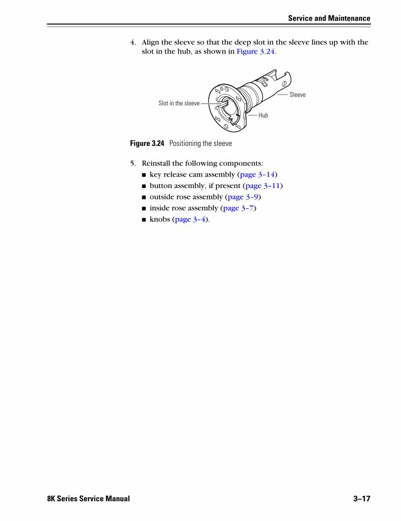
Service and Maintenance
4. Align the sleeve so that the deep slot in the sleeve lines up with the slot in the hub, as shown in Figure 3.24.
5. Reinstall the following components:
■ key release cam assembly (page 3–14)
■ button assembly, if present (page 3–11)
■ outside rose assembly (page 3–9)
■ inside rose assembly (page 3–7)
■ knobs (page 3–4).
Figure 3.24 Positioning the sleeve
Sleeve
Hub
Slot in the sleeve
8K Series Service Manual 3–17

Service and Maintenance
REPLACING COMPONENTS FOR ELECTRIFIED FUNCTION LOCKS
Replacing theinside rose and
rose liner
To remove the inside rose and rose liner:1. Remove the inside knob (page 3–3).
2. Insert the solid, curved end of the KD317 spanner wrench in between the rose and the sleeve, as shown in Figure 3.25. Pry the rose until it pops off of the liner.
3. Unscrew the two through-bolts, as shown in Figure 3.26. Save the through-bolts.
4. If there is an RQE rose liner, disconnect it.
5. Slide the liner off of the sleeve.
Figure 3.25 Removing the inside rose with the KD317 spanner wrench
KD317 spanner wrench
Inside rose
Sleeve
Figure 3.26 Removing the two through-bolts
Through-bolt
Through-bolt
Liner
3–18 8K Series Service Manual

Service and Maintenance
To reinstall the inside rose and rose liner:1. Align the holes in the liner with the holes prepared in the door.
2. Install the two through-bolts through the liner and door in the top and bottom holes.
3. Tighten the liner onto the door with the through-bolts.
4. If there is an RQE rose liner, connect it.
5. Install the rose.
6. Reinstall the knob (page 3–4).
Replacing theoutside rose
and linerassembly
To remove the outside rose and liner assembly:1. Remove the following components:
■ knobs (page 3–3)
■ inside rose and rose liner (page 3–18).
2. Slide the chassis assembly out of the door.
3. Retract the rose locking pin, and rotate the rose and liner assembly counterclockwise until it is free from the hub.
Figure 3.27 Replacing the inside rose and rose liner
Through-bolt
Through-bolt
Rose liner
Rose
8K Series Service Manual 3–19

Service and Maintenance
4. Remove the rose and liner assembly from the sleeve.
To reinstall the outside rose and liner assembly:1. Retract the rose locking pin, and rotate the rose and liner assembly
clockwise until the proper door thickness groove on the through-bolt stud lines up with the hub face.
2. Release the rose locking pin. It should lock into the rose liner.
3. Install the lock chassis assembly from the outside. Make sure the latch tabs engage the chassis frame and the latch tailpiece engages the retractor.
Figure 3.28 Removing the outside rose and liner assembly
Sleeve
Rose and liner assembly Rose locking pinRetractor-side view of the chassis
RetractorInside sleeve
Head-on view of the rose and liner assembly from the inside sleeve side
Rose locking pin
Retractor
Rose and liner assembly
Figure 3.29 Replacing the outside rose and liner assembly
Rose and liner assembly
Through-bolt studDoor thickness groove
3–20 8K Series Service Manual

Service and Maintenance
4. Reinstall the following components:
■ inside rose and rose liner (page 3–8)
■ knobs (page 3–3).
Replacing theRQE rose liner
To remove the RQE rose liner:1. Remove the following components:
■ knobs (page 3–3)
■ inside rose and rose liner (page 3–18).
2. Disconnect the RQE connector.
3. Remove the through-bolts and the RQE rose liner.
To reinstall the RQE rose liner:1. Place the RQE rose liner on the chassis, aligning the holes in the
rose liner with the holes prepared in the door.
Caution
Make sure that there is clearance for the solenoid wire between the RQE rose liner and the door.
2. Install the through-bolts through the RQE rose liner and door in the top and bottom holes.
3. Tighten the RQE rose liner on the door with the through-bolts.
4. Connect the RQE connector.
5. Reinstall the following components:
■ inside rose and rose liner (page 3–8)
■ knobs (page 3–3).
Replacing thesolenoid
Because of the complex nature of this procedure, BEST recommends that you order a new cylindrical chassis. Contact your BEST representative.
Use the part numbers listed in Reversing the solenoid when changing the function when ordering a new cylindrical chassis. See page 3–22.
8K Series Service Manual 3–21
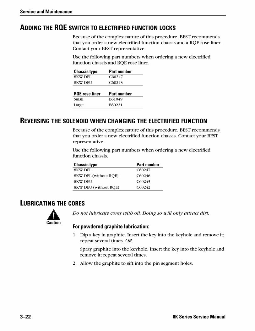
Service and Maintenance
ADDING THE RQE SWITCH TO ELECTRIFIED FUNCTION LOCKSBecause of the complex nature of this procedure, BEST recommends that you order a new electrified function chassis and a RQE rose liner. Contact your BEST representative.
Use the following part numbers when ordering a new electrified function chassis and RQE rose liner.
REVERSING THE SOLENOID WHEN CHANGING THE ELECTRIFIED FUNCTIONBecause of the complex nature of this procedure, BEST recommends that you order a new electrified function chassis. Contact your BEST representative.
Use the following part numbers when ordering a new electrified function chassis.
LUBRICATING THE CORES
Caution
Do not lubricate cores with oil. Doing so will only attract dirt.
For powdered graphite lubrication:1. Dip a key in graphite. Insert the key into the keyhole and remove it;
repeat several times. OR
Spray graphite into the keyhole. Insert the key into the keyhole and remove it; repeat several times.
2. Allow the graphite to sift into the pin segment holes.
Chassis type Part number8KW DEL C60247
8KW DEU C60243
RQE rose liner Part numberSmall B61049
Large B60221
Chassis type Part number8KW DEL C60247
8KW DEL (without RQE) C60246
8KW DEU C60243
8KW DEU (without RQE) C60242
3–22 8K Series Service Manual

Service and Maintenance
For silicone type lubrication:1. Clean all existing lubricant out of the core.
Caution
Do not mix graphite with a silicone-type lubricant.
2. With the core inverted, spray the lubricant into the key opening allowing the spray to penetrate the pin segment holes.
Note: When cores are installed and exposed to harsh weather conditions, silicone-type lubricants can help displace moisture as well as spread into pin segment holes and other surfaces.
ALIGNING THE CHASSIS AND TRIMEstablish a schedule to inspect locks, doors, and door hardware for proper alignment and operation. Occasionally a lock chassis and/or rose trim may become loose and require tightening.
To retighten a loose or misaligned chassis or rose trim:1. Remove the inside trim. Instructions begin on page 3–3.
2. Align the chassis with the latch. Make sure that the latch tabs engage the chassis frame and the latch tailpiece engages the retractor, as shown in Figure 3.30.
3. Tighten the chassis screws.
4. Test the knob operation to make sure that the latch tailpiece does not bind with the chassis retractor.
5. Reinstall the inside trim. Instructions begin on page 3–3.
Figure 3.30 Engaging the retractor in the latch
Chassis frameLatch tab
Latch tailpiece
Retractor
Chassis frame
8K Series Service Manual 3–23

Service and Maintenance
CAM POSITIONING INSTRUCTIONS
Positioning the camfor C function locks
Vibration during the shipment of the C function locks may cause the inside locking cam to rotate out of position. It is possible to insert the core and throw member in this incorrect position, but faulty operation will result. You might notice this problem in one of the following ways.
■ The inside key does not rotate the full 360 degrees and the outside key does not rotate the full 135 degrees. Remove the inside core and throw member, and perform the steps below to reposition the inside locking cam.
■ Before you install the core and throw member, you can see that the inside locking cam is not positioned as shown in Figure 3.31. Perform the following steps to reposition the inside locking cam.
To reposition the locking cam:1. Be sure the inside knob locking cam, which engages the throw
member, is rotated. Looking into the figure-8 core hole in the inside knob, turn the locking cam ears to match the position shown in Figure 3.31.
2. With the lock in the locked position, install the core and throw member.
3. Check the operation of the knobs while the door is open. The outside knob is locked by rotating the inside key 360 degrees clockwise and unlocked by rotating the inside key 360 degrees counterclockwise.
Figure 3.31 Correct position of the C function inside locking cam
Locking cam ears
Figure-8 core hole
3–24 8K Series Service Manual

Service and Maintenance
Positioning thecam for G function
locks
Vibration during the shipment of the G function locks may cause the inside locking cam to rotate out of position. It is possible to insert the core and throw member in this incorrect position, but faulty operation will result. You might notice this problem in one of the following ways.
■ With the knobs in the locked position, both the inside and outside keys do not rotate one full turn in both directions. Remove both cores and throw members, and perform the following steps to reposition the locking cam.
■ Before you install the core and throw member, you can see that the locking cam is not positioned as shown in Figure 3.32. Perform the following steps to reposition the locking cam.
To reposition the locking cam:1. Looking through the figure-8 core hole in either knob, turn the
locking cam drive slot to match the position shown in Figure 3.32.
2. With the lock in the locked position, install that knob’s core and throw member.
Figure 3.32 Correct position of the G function locking cam
Locking cam drive slot
Figure-8 core hole
8K Series Service Manual 3–25

Service and Maintenance
3. Looking into the figure-8 core hole in the other knob, turn the locking cam drive slot until it stops, as shown in Figure 3.33.
4. Turn the drive slot clockwise to match the position shown in Figure 3.32.
5. Reinstall that knob’s core and throw member.
6. Check the operation of the knobs while the door is open. The knobs are locked by rotating the key 1 1/4 turns counterclockwise and unlocked by rotating the key 1 1/4 turns clockwise.
Positioning the camfor R, S, & T function
locks
Vibration during the shipment of the R, S, & T function locks may cause the locking cam to rotate out of position. It is possible to insert the core and throw member in this incorrect position, but the lock will not function properly. You might notice this problem in one of the following ways.
■ The inside key does not rotate the full 360 degrees and/or the outside key does not rotate the full 135 degrees. Remove the core and throw member, and perform the steps below to reposition the inside locking cam.
■ Before you install the core and throw member, you can see that the locking cam is not positioned as shown in Figure 3.34. Perform the following steps to reposition the locking cam.
Figure 3.33 Intermediate position of the G function locking cam
Locking cam drive slot
Figure-8 core hole
3–26 8K Series Service Manual

Service and Maintenance
To reposition the locking cam:1. Be sure the locking cam, which engages the throw member, is
rotated counterclockwise. Looking into the figure-8 core hole in the knob, turn the locking cam ears counterclockwise to match the position shown in Figure 3.34.
2. With the lock in the locked position, install the core and throw member.
For the S function, repeat Steps 1 and 2 for the other side of the lock. For the R and T functions, go to Step 3.
3. Check the operation of the knobs while the door is open. The knob is locked by rotating the key 360 degrees counterclockwise and unlocked by rotating the key 360 degrees clockwise.
Note: For T function locks, when the outside knob is locked by the key, the knob remains locked even though the push button is released from turning the inside knob or closing the door.
Figure 3.34 Correct position of the R, S, & T function locking cam
Locking cam ears
Figure-8 core hole
8K Series Service Manual 3–27

Service and Maintenance
EMERGENCY KEY INSTRUCTIONS FOR H AND HJ FUNCTION LOCKS
To use the emergency key:1. Remove the core and throw member (page 3–3).
2. Insert the blade of the emergency key into the slot of the figure-8 core hole, as shown in Figure 3.35.
3. Turn the key and retract the latch.
Figure 3.35 Inserting the emergency key
Emergency key
Figure-8 core hole
Outside of door
3–28 8K Series Service Manual

Service and Maintenance
TROUBLESHOOTINGThis table summarizes the possible causes for certain lock problems. The causes are listed in the order of likelihood. (The most likely cause is first, and so forth.)
You notice… Possible causes include… You should…Knob won’t return to its normal position.
There is binding between the knob and rose.
Ensure that the lock chassis is centered within the door (pg. 3-23).
Key spins freely, but won’t retract the latch or unlock the door.
a. Throw member is not installed. a. Install the throw member.
b. 6-pin core is installed with a 7-pin throw member.
b. Change the core or throw member.
c. Knob driver is not installed. c. Install the knob driver (pg. 3-6).
Core doesn’t fit into the knob core hole.
a. 7- pin core is installed with a 6-pin throw member.
a. Change the core or throw member.
b. Keyed knob is defective. b. Replace the keyed knob (pg. 3-4).
Button doesn’t pop out as expected. Button shaft is damaged or bent. Replace the button assembly (pg. 3-10).
Latch doesn’t retract. a. Latch tailpiece is broken. a. Replace the latch assembly.
b. Latch tailpiece didn’t engage the retractor correctly during installation.
b. Reinstall the lock chassis (pg. 3-23).
For a C function lock, the inside key does not rotate the full 360°, and the outside key doesn’t rotate the full 135°.
Inside locking cam is out of position. Reposition the inside locking cam (pg. 3-24).
For a G function lock with knobs in the locked position, the key doesn’t rotate one full turn in both directions.
Locking cam is out of position. Reposition the locking cam (pg. 3-25).
For R, S, and T function locks, the key doesn’t rotate one full turn in both directions.
Locking cam is out of position. Reposition the locking cam (pg. 3-26).
Cannot remove the operating key from an H or HJ function lock.
Key is turned 180 degrees past the correct position.
Push the inside button, turn the key back 180°, and remove the key.
8K Series Service Manual 3–29

Service and Maintenance
3–30 8K Series Service Manual

A
8K Series Service
INSTALLATION INSTRUCTIONS
The following pages contain the Installation Instructions for 8K Cylindrical Locks and the Wiring Instructions for 8K & 9K Series Electrified Cylindrical Locks.
Manual A–1

Installation Instructions
A–2 8K Series Service Manual

BEST ACCESS SYSTEMSIndianapolis, Indiana
1
Preparing the door
For factory prepared doors only
1 Install the latch so that the bevel on the latchbolt faces the strike lip.
2 Adjust the outside rose so that the chassis is centered in the door. Install the chassis from the outside of the door.
3 Install the inside rose, rose ring, knob, and strike plate.
Caution: If you use fabricated hollow metal doors, determine whether the doors are reinforced enough to support the lock. If the door reinforce-ment is not adequate, consult the door manufac-turer for information on proper reinforcement.
Note: For detailed installation instructions, see the fol-lowing steps.
1 Position template
1 Fold the template and place it in position on the high edge of the door bevel. (See Figure 2.)
2 Mark the drill points.
Note: Suggested height from floor to centerline of the lock is 40 5/16″. If steel frames are used, the latch center-line must be in line with the center of the strike prepara-tion.
Figure 1 Overview diagram
Rose ring
Rose
Latch
Deadlock-ing plunger
Bevel on latchbolt
Lock chassis
Figure 2 Marking the drill points
High edge of door bevel
Installation Instructions for 83K–85K Cylindrical Locks

Installation Instructions for 83K–85K Cylindrical Locks
BEST ACCESS SYSTEMSIndianapolis, Indiana
T56066/Rev A 1797947 ER-7991-12 May 20032
Preparing the lock
2 Bore holes and install latch
1 Bore a 2 1/8″ diameter hole from both sides of the door to the center of the door. (See Figure 3.)
2 Drill a 1″ diameter hole from the edge of the door that intersects the 2 1/8″ hole.
3 Mortise the door edge for the latch face.4 Install the latch and check the door swing. Latch tabs
should project into the 2 1/8″ diameter hole. See Task 5, Install chassis.
3 Remove inside knob and trim
For inside knobs with button or blank face:
1 Insert the spanner wrench tip into the knob keeper hole and depress the keeper. (See Figure 4.)
2 Slide the knob off.3 Unthread the rose ring and remove the rose.
For keyed inside knobs:
1 Remove the core and throw member (if not already removed). For instructions on removing the core, see Task 9, Install core.
2 Insert a screwdriver into the figure-8 core hole and into the keeper. (See Figure 4, top.)
3 Using the edge of the screwdriver, press down on the keeper and slide the keyed knob off of the sleeve.
Caution: You will not be able to remove the knob if you put the screwdriver blade too far past the keeper.
4 Center lock in door
Check to see if the lock retractor is centered in the door.
■ If centered, proceed to Task 5, Install core.■ If not centered, use the door as a reference and center
the retractor in the door. Do this by pulling the rose locking pin and rotating the outside rose in or out. (See Figure 5.)
Caution: Center the retractor before proceeding to Step 5, Install chassis.
Figure 3 Boring holes and installing the latch
2 1/8″ dia hole
1″ dia hole
Latch tabs
Latch face
Figure 4 Removing inside knob and trim
Figure-8 core hole
Knob keeper
Knob keeper spring
Insert screwdriver blade here
Spanner wrench
Knob keeper hole
Figure 5 Marking the centerlines
Rose
Retractor
Pull pin to rotate rose

Installation Instructions for 83K–85K Cylindrical Locks
BEST ACCESS SYSTEMSIndianapolis, Indiana
3
Installation Instructions for 83K–85K Cylindrical Locks
Installing the lock
Note 1: Make sure the locking pin locks back into the rose liner.
Note 2: Locks with standard trim will fit doors 1 3/8″ to 2 1/8″ thick. Locks with ‘E’ trim will fit doors 2 1/4″ to 3″ thick.
5 Install chassis
■ After the retractor has been centered, and with the latch in place, install the chassis from the outside of the door. Make sure the latch tabs fit into the chassis frame and the latch tailpiece fits into the retractor. (See Figure 6.)
6 Install inside rose and knob
Note: For lead lined locksets, slide the lead shield (not shown) over the sleeve and into the 2 1/8″ hole.
1 Slide the rose over the sleeve, then thread the rose ring onto the threaded hub and tighten snugly with the spanner wrench.
For non-keyed inside knobs:2 Align the knob keeper hole with the knob keeper in
the sleeve as shown in Figure 7. Firmly push the knob on until seated.
For keyed inside knobs:2 Align either of the knob driver slots with the knob
driver in the sleeve as shown in Figure 8. Firmly push the knob on until seated.
Figure 6 Installing the chassis
Chassis frameLatch tab
Latch tailpiece
Retractor
Chassis
Enlarged view
Figure 7 Installing the inside knob and rose
Spanner wrenchRose
Rose ring
SleeveKnob keeper
Knob keeper hole
Figure 8 Installing the inside keyed knob
Knob driver slots
Knob keeper
Knob driver

Installation Instructions for 83K–85K Cylindrical Locks
BEST ACCESS SYSTEMSIndianapolis, Indiana
T56066/Rev A 1797947 ER-7991-12 May 20034
Completing the installation
7 Install strike plate
1 Mortise the door jamb to fit the strike box and strike plate. Make sure to align the strike plate and latchbolt centers.
Caution: The deadlocking plunger of the latchbolt must not enter the strike plate. The plunger deadlocks the latchbolt and prevents forcing the latch when the door is closed. Excessive gap may reduce security and/or cause malfunction of the latchbolt assembly. A maxi-mum door gap of 1/8″ is recommended.
2 Insert the strike box and secure the strike plate with the screws provided.
8 Check handing
Note: When Best 8K locksets are properly installed, the figure-8 hole must be in the upper half of the knob. If it is not, change the hand of the lock.
To change the hand of the lock:■ Rotate the knob face 180 degrees so that the figure-8
is in the upper half of the knob.
9 Install core
For 6-pin core users only: Slide the spacer — sup-plied with your 6-pin cores — over the 7-pin throw member (see Figure 11, top right).
Note: If you have ordered 6-pin cores, you will get one spacer per core with your order. Spacers are not supplied with locks.
1 Insert the throw member (or throw member and spacer) into the back of the core (see Figure 11, top).
2 Put the control key into the core and turn the key 15 degrees clockwise.
3 Put the core and throw member into the knob with the control key (see Figure 11, bottom).
4 Turn the key 15 degrees counterclockwise and remove the key.
Caution: Since the control key is a high-security key, make sure to keep it protected.
Figure 9 Installing the strike
Door jamb
Strike box
Strike plate
Figure 10 Turning the knob face to correct the handing of the lock
Incorrect Correct
Rotate Knob faceFigure-8 hole
1
2
Figure 11 Installing the figure-8 core
BEST
BE
ST
7-pin core 6-pin core
Spacer
Control key in core

BEST ACCESS SYSTEMS
Indianapolis, Indiana
Electrical requirements
The following table describes the voltage and current specifications for
the 8K and 9K locks, with RQE (REX) switch, and door monitoring switch.
Parts list
The following table describes the parts illustrated in Figure 1. You may
substitute most components with equivalent parts.
Unit
Voltage
Current
8K (RQE not available)
24 volts DC
0.18 amp continuous
duty
9K with and without
RQE
24 volts DC
0.169 amp continu-
ous duty
RQE switch
30 volts DC maxi-
mum
0.7 amp inductive
0.7 amp resistive
Part number
Description
8W599
Transformer—24 volt AC, 40 volt-amps. See the
examples under Installation Hints on the reverse side.
8WDTL
Door transfer loop. You may substitute this with a
power transfer hinge.
8WMOV
Metal oxide varistor
8WCON
AC to DC converter (full-wave bridge rectifier)
Wiring diagram
The diagram below shows how to wire 8K and 9K electrified locks.
Figure 1—Wiring diagram for 8K and 9K electrified locks (9K with RQE shown)
8WMOVUse this component on power wires to reduce electrical surges.
Run wires through the door or mount wires to the door sur-face with wire molding.To find the correct wire gauge for wire runs, see Figure 2 on the reverse side.
RQE (Request-to-exit) wires are normally used with access control systems.
8WDTL Door transfer loop
Ceiling
Brown (common)
Orange (Normally open)
Green (Normally closed)
24 volts AC 60 Hz. in
120 volts AC 60 Hz. in
Electrified cylindrical chassis — 9K shown with RQE
24 volts DC 60 Hz. out
8W599Transformer
8WCONAC to DC converter
RQE (Request-to-exit) wires
(Over)
T56090/Rev A 1800760 ER-7991-19 Mar 2000
Wiring Instructions for 8K and 9K Series
Electrified Cylindrical Locks with Request-to-exit

BEST ACCESS SYSTEMS
Indianapolis, Indiana
Minimum gauge wire chart for lock circuits
The chart in Figure 2 helps you find the minimum wire gauge needed for a specific length wire run. It assumes that the lock circu
it is made of two con-
ductor cable. The chart also factors in a 15% voltage loss at 24 volts.
Figure 2—Minimum gauge wire chart for lock circuits
10 AWG wire12 AWG wire14 AWG wire16 AWG wire
18 AWG wire20 AWG wire
Example
Do not use this chart for any plots made to this shaded area.
1.500
1.375
1.250
1.125
1.000
.875
.750
.625
.500
.375
.250
.125
0
500'
1000
'
1500
'
2000
'
2500
'
3000
'
3500
'
4000
'
Maximumlock current
(in amps)
Total footage of two conductor cable for lock circuit (in feet)
To find the correct gauge wire
1
Determine the maximum lock current and find that value on the left
side of the chart.
2
Determine the total footage of cable to be used in the lock circuit
and find that value at the bottom of the chart.
3
Locate the intersection of current and footage. The line above or to
the right of the intersection shows what minimum gauge wire you
need.
Example▲
Lock current:
0.169 amp maximum▲
Total wire run:
1000 feet
Wire gauge needed:
20 AWG two conductor cable
Note:
For 12 volt locks, double the maximum lock current, then use
that value on the left side of the chart.
Installation hints
1
Wire gauge (or size) determines how efficiently the lock will operate.
Consider wire gauge before installation. To find the recommended
minimum wire gauge for all wire runs, see Figure 2.
2
Use wire of 20 AWG (gauge) or larger. We do not recommend using a
smaller wire gauge than 20 AWG.
3
When wiring two or more locks to a single power supply, make sure
that the power rating of the power supply is 1
½
times greater than
the sum of the lock’s power requirement.
Example
For two locks powered by one supply:
▲
Lock 1 (8K) is rated at 24 volts, 0.18 amps—
24 volts ×
0.18 amps
= 4.32 volt-amps▲
Lock 2 (35H) is rated at 24 volts, 0.75 amps—
24 volts ×
0.75 amps
= 18 volt-amps
Choose a transformer with a rating of at least: (4.32 volt-amps + 18
volt-amps) ×
1
½
=
33.48 volt-amps
T56090/Rev A 1800760 ER-7991-19 Mar 2000

B
8K Series Service
INDEX
Numerics8W components 2–58
AA chassis
function conversion for 2–47function description for 2–7part numbers and drawings for 2–26
AB chassisfunction conversion for 2–46function description for 2–3part numbers and drawings for 2–11
AC to DC converter 2–58aligning the chassis and trim 3–23
BB chassis
function conversion for 2–47function description for 2–7part numbers and drawings for 2–27
boring jig kit 2–61bridge bar 2–32button assembly
button release assembly 2–17push button assembly 2–16 to 2–17,
2–20, 2–23, 2–27, 2–31reinstalling 3–11removing 3–10slotted button assembly 2–14, 2–30turn button assembly 2–11, 2–26, 2–31
to 2–33
CC chassis
cam positioning instructions for 3–24, 3–26
function conversion for 2–46function description for 2–5part numbers and drawings for 2–12
cam positioning instructionsfor C chassis 3–24, 3–26for G chassis 3–25for R, S, and T chassis 3–26
certifications and standards 1–1chassis cover 2–11 to 2–41chassis screw 2–11 to 2–41clamp stud 2–11 to 2–41cores, lubricating 3–22
DD chassis
function conversion for 2–46function description for 2–3part numbers and drawings for 2–13
DEL chassisfunction conversion for 2–48function description for 2–10
DEU chassisfunction conversion for 2–48function description for 2–10
diagrams, explodedsee part numbers and drawings
documentation package 1–2door projections 2–56door transfer loop 2–58
Manual B-1

Index
double dummy trimfunction description for 2–6part numbers and drawings for
2–57DR chassis
function conversion for 2–47function description for 2–7part numbers and drawings for
2–28drawings, of parts
see part numbers and drawingsdummy trim
double 2–6, 2–57single 2–6, 2–57
DZ chassisfunction conversion for 2–47function description for 2–7part numbers and drawings for
2–29
EE chassis
function conversion for 2–46function description for 2–3part numbers and drawings for
2–14EA chassis
function conversion for 2–47function description for 2–8part numbers and drawings for
2–30emergency driver 3–2exploded diagrams
see part numbers and drawings
Ffaceplate marking chisel 2–60 to
2–61function conversion
reversing the solenoid 3–22function description
for A chassis 2–7for AB chassis 2–3for B chassis 2–7for C chassis 2–5for D chassis 2–3for DEL chassis 2–10for DEU chassis 2–10for double dummy trim 2–6for DR chassis 2–7for DZ chassis 2–7for E chassis 2–3for EA chassis 2–8
for G chassis 2–5for H and HJ chassis 2–3for L chassis 2–6for LL chassis 2–8for M chassis 2–8for N chassis 2–6for NX chassis 2–6for P chassis 2–6for Q chassis 2–8for R chassis 2–4for RD chassis 2–8for RH chassis 2–8for RZ chassis 2–9for S chassis 2–5for single dummy trim 2–6for T chassis 2–4for W chassis 2–5for XD chassis 2–9for XR chassis 2–9for Y chassis 2–6for YD chassis 2–9for YR chassis 2–9for Z chassis 2–9
GG chassis
cam positioning instructions for 3–25
function conversion for 2–46function description for 2–5part numbers and drawings for
2–15
HH and HJ chassis
function conversion for 2–46function description for 2–3key instructions for 3–28part numbers and drawings for
2–16
Iinside hub and plate assembly 2–11
to 2–41
Kkey instructions for H and HJ chassis
3–28key release cam assembly 2–11 to
2–17, 2–19 to 2–24, 2–26 to 2–40
reinstalling 3–14
removing 3–13knob driver 2–11 to 2–15, 2–21 to
2–24, 2–26 to 2–31, 2–34 to 2–40
reinstalling 3–6removing 3–6
knob keeper springreinstalling 3–13removing 3–12
knobspart numbers and drawings for
2–51, 2–54, 2–56reinstalling 3–4removing 3–3 to 3–4
LL chassis
function conversion for 2–46function description for 2–6part numbers and drawings for
2–17latches 2–59lead-lined parts 2–50lever keeper spring 2–55LL chassis
function conversion for 2–47function description for 2–8part numbers and drawings for
2–31lock chassis
aligning 3–23reinstalling in the door 3–10,
3–20removing from the door 3–8,
3–19locking bar 2–12, 2–15locking bar assembly for NX
function 2–19lubricating cores 3–22
MM chassis
function conversion for 2–47function description for 2–8part numbers and drawings for
2–32metal oxide varistor 2–58
NN chassis
function conversion for 2–46function description for 2–6part numbers and drawings for
B-2 8K Series Service Manual
Index
non-standard strikes 2–49numbers, for parts
see part numbers and drawingsNX chassis
function conversion for 2–46function description for 2–6
Ooutside hub and plate assembly
2–11 to 2–15, 2–17 to 2–41
outside rose for Y function 2–25, 2–39 to 2–40
PP chassis
function conversion for 2–46function description for 2–6part numbers and drawings for
2–20part numbers and drawings
for 8W components 2–58for A chassis 2–26for AB chassis 2–11for B chassis 2–27for C chassis 2–12for D chassis 2–13for double dummy trim 2–57for DR chassis 2–28for DZ chassis 2–29for E chassis 2–14for EA chassis 2–30for G chassis 2–15for H and HJ chassis 2–16for L chassis 2–17for latches 2–59for LL chassis 2–31for M chassis 2–32for N chassis 2–18for non-standard strikes 2–49for P chassis 2–20for Q chassis 2–33for R chassis 2–21for RD chassis 2–34for RH chassis 2–35for roses and rose rings 2–51for roses, rose liners, and rose
spacers 2–52 to 2–53for RZ chassis 2–36for S chassis 2–22for single dummy trim 2–57for standard knobs 2–51, 2–54,
2–56for standard strikes and strike
boxes 2–49
for T chassis 2–23for W chassis 2–24for XD chassis 2–37for XR chassis 2–38for Y chassis 2–25for YD chassis 2–39for YR chassis 2–40for Z chassis 2–41
plate 2–58projections, from door 2–56
QQ chassis
function conversion for 2–47function description for 2–8part numbers and drawings for
2–33
RR chassis
cam positioning instructions for 3–26
function conversion for 2–46function description for 2–4part numbers and drawings for
2–21RD chassis
function conversion for 2–47function description for 2–8part numbers and drawings for
2–34reinstalling
button assembly 3–11inside rose and rose liner 3–19inside rose assembly 3–8key release cam assembly 3–14knob driver 3–6knob keeper spring 3–13knobs 3–4lock chassis in the door 3–10,
3–20outside rose and liner assembly
3–20outside rose assembly 3–9RQE rose liner 3–21sleeve assembly 3–16solenoid 3–21
removingbutton assembly 3–10inside rose and rose liner 3–18inside rose assembly 3–7key release cam assembly 3–13keyed knob 3–3knob driver 3–6knob keeper spring 3–12
lock chassis from the door 3–8, 3–19
outside rose and liner assembly 3–19
outside rose assembly 3–8plain or button knob 3–4sleeve assembly 3–16solenoid 3–21
retractor assemblywith long catchplate 2–11
, 2–14, 2–16 to 2–17, 2–20, 2–23, 2–31
with short catchplate 2–27, 2–30
without catchplate 2–12 to 2–13, 2–15, 2–18 to 2–19, 2–21 to 2–22, 2–24 to 2–26, 2–28 to 2–29, 2–32 to 2–41
RH chassisfunction conversion for 2–47function description for 2–8part numbers and drawings for
2–35RQE rose liner
reinstalling 3–21RZ chassis
function conversion for 2–47function description for 2–9part numbers and drawings for
2–36
SS chassis
cam positioning instructions for 3–26
function conversion for 2–46function description for 2–5part numbers and drawings for
2–22single dummy trim
function description for 2–6part numbers and drawings for
2–57sleeve assembly
keyed 2–11 to 2–15, 2–21 to 2–24, 2–26 to 2–31, 2–34 to 2–40
keyed sleeve and hub assembly 2–16
non-keyed 2–11, 2–13 to 2–14, 2–16 to 2–21, 2–23, 2–25 to 2–27, 2–29 to 2–33, 2–35 to 2–38, 2–41
8K Series Service Manual B-3

Index
non-keyed sleeve and driver assembly 2–30
reinstalling 3–16removing 3–16
solenoidreinstalling 3–21removing 3–21reversing for function
conversion 3–22spanner wrench
part number and drawing for 3–2
part number for 3–2using 3–4, 3–7, 3–18
standard strikes and strike boxes 2–49
strike plate locating pin 2–60 to 2–61
support, technical 1–3
TT chassis
cam positioning instructions for 3–26
function conversion for 2–46function description for 2–4part numbers and drawings for
2–23technical documentation package
1–2technical support 1–3temperature control module 2–58transformer 2–58trim
double dummy 2–57knobs 2–54latches 2–59non-standard stikes 2–49roses 2–51single dummy 2–57standard strikes and strike
boxes 2–49troubleshooting questions 3–29turn blade assembly for Z function
2–36, 2–41
WW chassis
function conversion for 2–46function description for 2–5part numbers and drawings for
2–24
XXD chassis
function conversion for 2–47function description for 2–9part numbers and drawings for
2–37XR chassis
function conversion for 2–47function description for 2–9part numbers and drawings for
2–38
YY chassis
function conversion for 2–46function description for 2–6part numbers and drawings for
2–25YD chassis
function conversion for 2–47function description for 2–9part numbers and drawings for
2–39YR chassis
function conversion for 2–47function description for 2–9part numbers and drawings for
2–40
ZZ chassis
function conversion for 2–47function description for 2–9part numbers and drawings for
2–41
B-4 8K Series Service Manual


![Adaptively Secure Distributed PRFs from LWE · A pseudorandom function (PRF) family [35] is a set Fof keyed functions with common domainDom andrangeRng suchthatno ppt adversarycandistinguisharealexperiment,](https://img.pdfslide.net/doc/110x75/5be63fdd09d3f23a518c908d/adaptively-secure-distributed-prfs-from-lwe-a-pseudorandom-function-prf-family.jpg)