Embed Size (px)
Citation preview
Low ambient kit para Roof Top D4IC y B4IH- 360, 480Instrucciones de Instalación
Ref: N-40207 0508
E
3 - 8
Low ambient Kit for Roof Top D4IC and B4IH- 360, 480Installation Instructions
GB
9 - 10
ITITIT
F
P
D
I
NL
N
Low ambient kit pour Roof Top D4IC et B4IH- 360, 480Instructions d'Installation 11 - 12
Low ambient kit para Roof Top D4IC e B4IH- 360, 480Instruções de Instalação 13 - 14
Kit low ambient per Roof TopD4IC e B4IH- 360, 480Istruzioni per l'Installazione 15 - 16
Low Ambient Kit für Roof Top D4IC und B4IH- 360, 480Hinweise zum Einbau 17 - 18
Low Ambient kit voor Roof Top D4IC en B4IH- 360, 480Installatie-instructies 19- 20
Low Ambient kit for Roof Top D4IC og B4IH- 360, 480Installasjonsinstrukser 21 - 22
� � � � � � � ����������������������
���������������
�����
�������������
������
Johnson Controls Manufacturing España, S.L. participa no Programa de Certificação EUROVENT.Os produtos correspondem aos referidos no Directório EUROVENT de Produtos Certificados, no programa AC1, AC2, AC3, LCP e FC.O programa LCP abrange instalações arrefecedoras condensadas por ar e bombas de calor até 600 kW.
Johnson Controls Manufacturing España, S.L. participa en el Programa de Certificación EUROVENT.Los productos se corresponden con los relacionados en el Directorio EUROVENT de Productos Certificados, en el programa AC1, AC2, AC3, LCP y FC.El LCP, abarca plantas enfriadoras condensadas por aire y bombas de calor hasta 600 kW.
Johnson Controls Manufacturing España, S.L. is participating in the EUROVENT Certification Programme.Products are as listed in the EUROVENT Directory of Certified Products, in the program AC1, AC2, AC3, LCP and FC.The LCP program covers air condensed water chillers and heat pumps of up to 600 kW
Johnson Controls Manufacturing España, S.L. participe au Programme de Certification EUROVENT.Les produits figurent dans l'Annuaire EUROVENT des Produits Certifiés, dans le programme AC1, AC2, AC3, LCP et FC.Le programme LCP recouvre les groupes refroidisseurs de liquides froid seul et réversible, à con-densation par air jusqu'à 600 kW.
Johnson Controls Manufacturing España, S.L. partecipa al Programma di Certificazione EUROVENT.I prodotti interessati figurano nell'Annuario EUROVENT dei Prodotti Certificati, nel programma AC1, AC2, AC3, LCP e FC.Il programma LCP è valido per refrigeratori d'acqua raffreddati ad aria e pompe di calore sino a 600 kW.
Johnson Controls Manufacturing España, S.L. ist am Zertifikationsprogramm EUROVENT beteiligt.Die entsprechend gekennzeichneten Produkte sind im EUROVENT-Jahrbuch im Programm AC1, AC2, AC3, LCP und FC. enthalten.Das LCP- Programm umfasst luftgekühlte Kühlanlagen und Wärmepumpen bis 600 kW.
Johnson Controls Manufacturing España, S.L. neemt deel aan het EUROVENT-certificatieprogramma.De produkten zijn opgenomen in het EUROVENT-jaarboek van de gecertificeerde produkten, in de programma AC1, AC2, AC3, LCP en FC.Het LCP programma omvat door lucht gecondenseerde koelaggregaten en warmtepompen tot 600 kW.
Johnson Controls Manufacturing España, S.L. deltar i EUROVENT sertifiseringsprogram.Produktene er oppført i EUROVENT's katalog over sertifiserte produkt, i kategoriene AC1, AC2, AC3, LCP og FC.LCP-programmet omfatter luftkondenserte kjøleanlegg og varmepumper opptil 600 kW.

3
Fig.1
�� �����
�
����
�
��
�
��
���
�� ����
��
��
���
�� �� �� �� �������� �����
��
������ ��� ���
��� ��� ��� ��� ���
������
��
�
�� ��
�����������������������
�
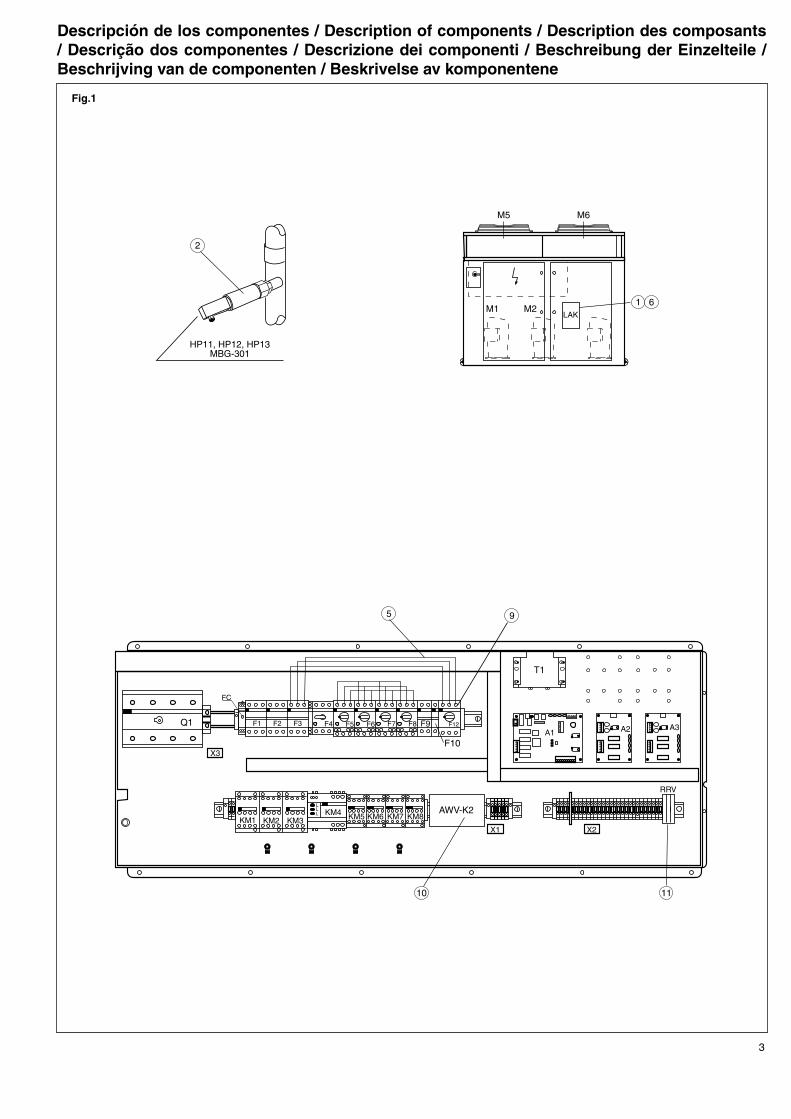
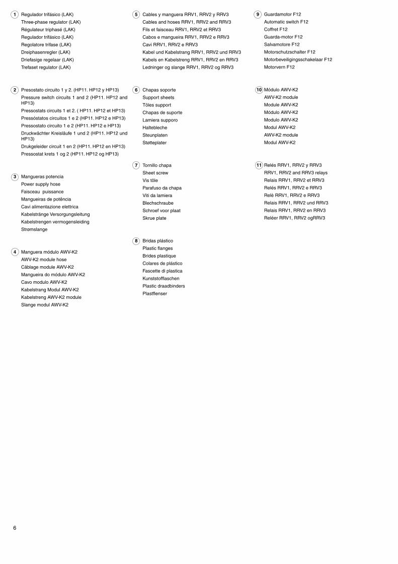
Descripción de los componentes / Description of components / Description des composants / Descrição dos componentes / Descrizione dei componenti / Beschreibung der Einzelteile / Beschrijving van de componenten / Beskrivelse av komponentene
4
Fig.2
�����
��� ���
�����
�����
�����
��
��
����������������������������������������������������������������������������������������������
������������������������������������������������������������������������������������������������������������������������������������������������������������������������
���������������������������������������������������������������������
�����������������������������������������������������
���������������������������������������������������
�����������������������������������������������������������
�����������������������������������������������������
���������������������������������������������������
�����������������������������������������������������������
��������������������������������������������������������������������������������������������
�
�
�
����
������� ���
����
����
�����
������������������������������������������������������������������������������������������������������������������������������������������������������������������������
���������������������������������������������������������������������
�����������������������������������������������������
���������������������������������������������������
�����������������������������������������������������������
�����������������������������������������������������
���������������������������������������������������
�����������������������������������������������������������
��� ���
�����
������
������
��
��
���������������������������������������������������������������������
���������������������������������������������������������������������
������������������������������������������������
������������������������������������������������
�����������������������������������������������������������
�����������������������������������������������������������
5
Fig.3
��� ���
�����
���
��
�
�
���������������������������������������������������
��������������������������������������������������������
���
���������������������������������������������������������������������������������������������
���������������������������������������������������������������������
�����������������������������������������������������������
�����������������������������������������������������������
���������������������������������������������������
��������������������������������������������������������
���������������������������������������������������������������������
����� ���
�����
������
������
��
��
�����������������������������������������������������������������������������������������
�����������������������������������������������������������
�����������������������������������������������������������
�����������������������������������������������������
�����������������������������������������������������
�������������������������������������������
����������������
� �������
�
��������������������������
��������������������
�������
� �������
� ������� ���
� � ������� ���
� ������� ��
� ��
� ��
�� ��
�� ��� ����� ����
�� ��� ����� ���
�� ��� ���
�� ��� ���
���������������������������������������������������
����������������������������������
���
��������������������
�������������
�����������������������������������������
�����������������������������������
������������������
��������������
�������������������������������������������
������������
�����������������������������������������������������������������
������������������������
�����������������������������������������
�����������
��������������������������������������
��������������������������������������
�
���
���
���
���
�
�
�
�
������������������������������������������
���������
����������������������
�����������������������
�������������������������
�������������������������
�������
�������
�������
�����
�����
����
����
����
�����
�����
�����
�������
�������
�������
�������
����
����
����
����
�
�
�
�
������������������������������������������
���������
��������������������������
��������������������
��������������������������
��������������������
����������������������������������������������
�����������
����������������������������������������������
�����������
����������������������������������������������
�����������
����������������������������������������������
�����������
�������������������������
�������������������������
�������������������������
�������������������������
6
1 Regulador trifásico (LAK)
Three-phase regulator (LAK)
Régulateur triphasé (LAK)
Regulador trifásico (LAK)
Regolatore trifase (LAK)
Dreiphasenregler (LAK)
Driefasige regelaar (LAK)
Trefaset regulator (LAK)
2 Presostato circuito 1 y 2. (HP11. HP12 y HP13)
Pressure switch circuits 1 and 2 (HP11. HP12 and HP13)
Pressostats circuits 1 et 2. ( HP11. HP12 et HP13)
Pressóstatos circuitos 1 e 2 (HP11. HP12 e HP13)
Pressostato circuito 1 e 2 (HP11. HP12 e HP13)
Druckwächter Kreisläufe 1 und 2 (HP11. HP12 und HP13)
Drukgeleider circuit 1 en 2 (HP11. HP12 en HP13)
Pressostat krets 1 og 2 (HP11. HP12 og HP13)
3 Mangueras potencia
Power supply hose
Faisceau puissance
Mangueiras de potência
Cavi alimentazione elettrica
Kabelstränge Versorgungsleitung
Kabelstrengen vermogensleiding
Strømslange
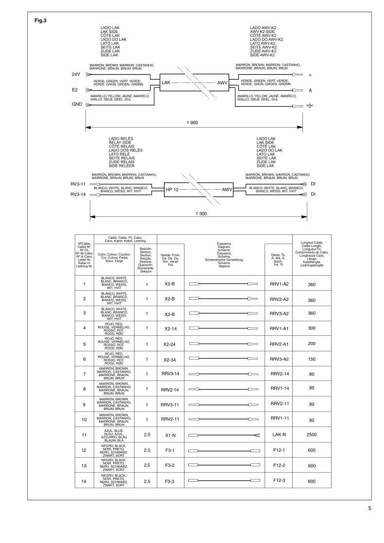
4 Manguera módulo AWV-K2
AWV-K2 module hose
Câblage module AWV-K2
Mangueira do módulo AWV-K2
Cavo modulo AWV-K2
Kabelstrang Modul AWV-K2
Kabelstreng AWV-K2 module
Slange modul AWV-K2
5 Cables y manguera RRV1, RRV2 y RRV3
Cables and hoses RRV1, RRV2 and RRV3
Fils et faisceau RRV1, RRV2 et RRV3
Cabos e mangueira RRV1, RRV2 e RRV3
Cavi RRV1, RRV2 e RRV3
Kabel und Kabelstrang RRV1, RRV2 und RRV3
Kabels en Kabelstreng RRV1, RRV2 en RRV3
Ledninger og slange RRV1, RRV2 og RRV3
6 Chapas soporte
Support sheets
Tôles support
Chapas de suporte
Lamiera supporo
Haltebleche
Steunplaten
Støtteplater
7 Tornillo chapa
Sheet screw
Vis tôle
Parafuso da chapa
Viti da lamiera
Blechschraube
Schroef voor plaat
Skrue plate
8 Bridas plástico
Plastic flanges
Brides plastique
Colares de plástico
Fascette di plastica
Kunststofflaschen
Plastic draadbinders
Plastflenser
9 Guardamotor F12
Automatic switch F12
Coffret F12
Guarda-motor F12
Salvamotore F12
Motorschutzschalter F12
Motorbeveiligingsschakelaar F12
Motorvern F12
10 Módulo AWV-K2
AWV-K2 module
Module AWV-K2
Módulo AWV-K2
Modulo AWV-K2
Modul AWV-K2
AWV-K2 module
Modul AWV-K2
11 Relés RRV1, RRV2 y RRV3
RRV1, RRV2 and RRV3 relays
Relais RRV1, RRV2 et RRV3
Relés RRV1, RRV2 e RRV3
Relè RRV1, RRV2 e RRV3
Relais RRV1, RRV2 und RRV3
Relais RRV1, RRV2 en RRV3
Reléer RRV1, RRV2 ogRRV3
7
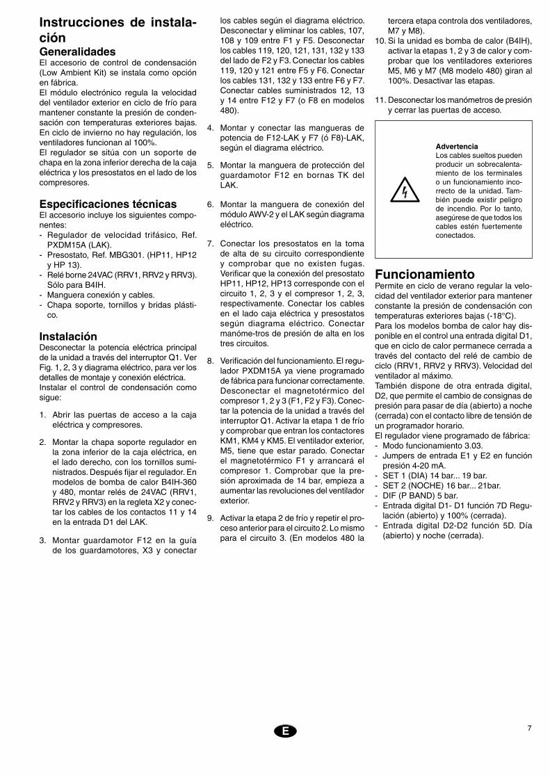
Instrucciones de instala-ciónGeneralidadesEl accesorio de control de condensación (Low Ambient Kit) se instala como opción en fábrica.El módulo electrónico regula la velocidad del ventilador exterior en ciclo de frío para mantener constante la presión de conden-sación con temperaturas exteriores bajas. En ciclo de invierno no hay regulación, los ventiladores funcionan al 100%.El regulador se sitúa con un soporte de chapa en la zona inferior derecha de la caja eléctrica y los presostatos en el lado de los compresores.
Especificaciones técnicasEl accesorio incluye los siguientes compo-nentes:- Regulador de velocidad trifásico, Ref.
PXDM15A (LAK).- Presostato, Ref. MBG301. (HP11, HP12
y HP 13).- Relé borne 24VAC (RRV1, RRV2 y RRV3).
Sólo para B4IH.- Manguera conexión y cables.- Chapa soporte, tornillos y bridas plásti-
co.
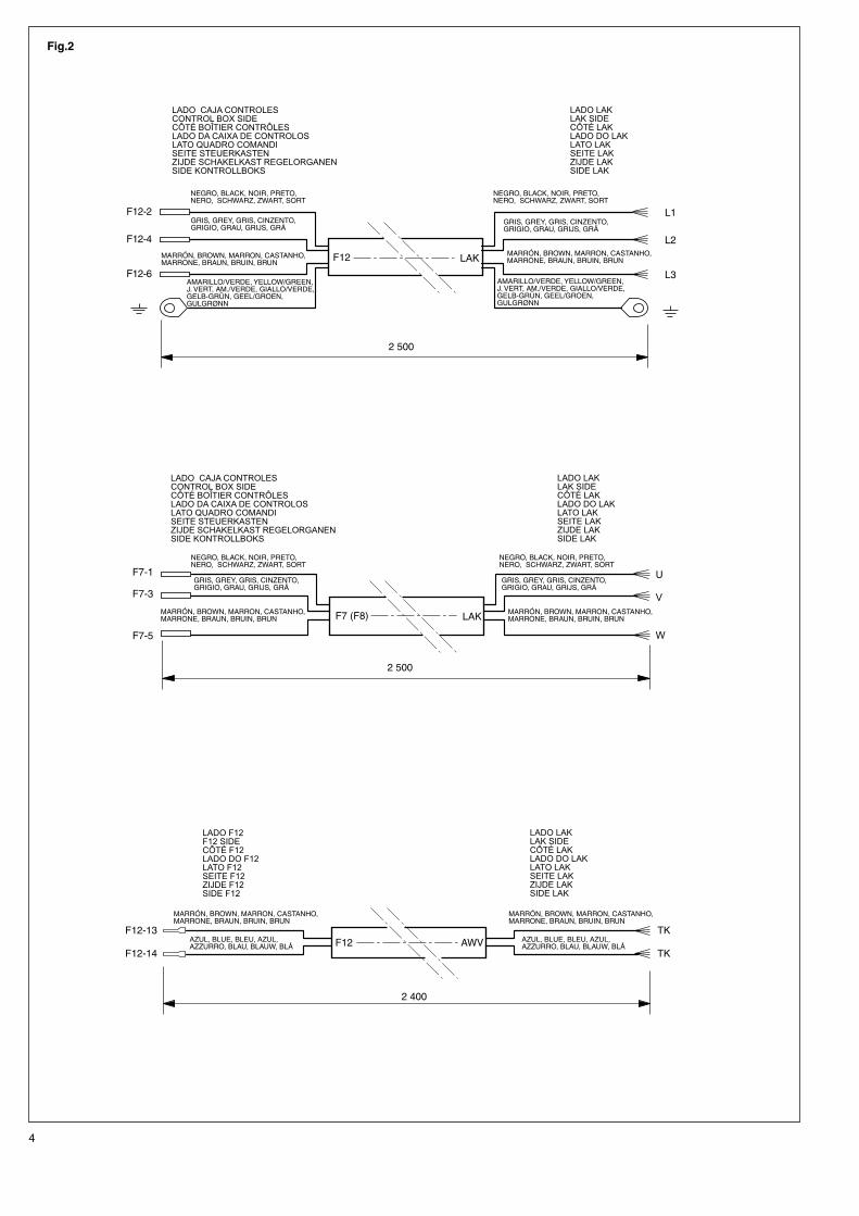
InstalaciónDesconectar la potencia eléctrica principal de la unidad a través del interruptor Q1. Ver Fig. 1, 2, 3 y diagrama eléctrico, para ver los detalles de montaje y conexión eléctrica.Instalar el control de condensación como sigue:
1. Abrir las puertas de acceso a la caja eléctrica y compresores.
2. Montar la chapa soporte regulador en la zona inferior de la caja eléctrica, en el lado derecho, con los tornillos sumi-nistrados. Después fijar el regulador. En modelos de bomba de calor B4IH-360 y 480, montar relés de 24VAC (RRV1, RRV2 y RRV3) en la regleta X2 y conec-tar los cables de los contactos 11 y 14 en la entrada D1 del LAK.
3. Montar guardamotor F12 en la guía de los guardamotores, X3 y conectar
los cables según el diagrama eléctrico. Desconectar y eliminar los cables, 107, 108 y 109 entre F1 y F5. Desconectar los cables 119, 120, 121, 131, 132 y 133 del lado de F2 y F3. Conectar los cables 119, 120 y 121 entre F5 y F6. Conectar los cables 131, 132 y 133 entre F6 y F7. Conectar cables suministrados 12, 13 y 14 entre F12 y F7 (o F8 en modelos 480).
4. Montar y conectar las mangueras de potencia de F12-LAK y F7 (ó F8)-LAK, según el diagrama eléctrico.
5. Montar la manguera de protección del guardamotor F12 en bornas TK del LAK.
6. Montar la manguera de conexión del módulo AWV-2 y el LAK según diagrama eléctrico.
7. Conectar los presostatos en la toma de alta de su circuito correspondiente y comprobar que no existen fugas. Verificar que la conexión del presostato HP11, HP12, HP13 corresponde con el circuito 1, 2, 3 y el compresor 1, 2, 3, respectivamente. Conectar los cables en el lado caja eléctrica y presostatos según diagrama eléctrico. Conectar manóme-tros de presión de alta en los tres circuitos.
8. Verificación del funcionamiento. El regu-lador PXDM15A ya viene programado de fábrica para funcionar correctamente. Desconectar el magnetotérmico del compresor 1, 2 y 3 (F1, F2 y F3). Conec-tar la potencia de la unidad a través del interruptor Q1. Activar la etapa 1 de frío y comprobar que entran los contactores KM1, KM4 y KM5. El ventilador exterior, M5, tiene que estar parado. Conectar el magnetotérmico F1 y arrancará el compresor 1. Comprobar que la pre-sión aproximada de 14 bar, empieza a aumentar las revoluciones del ventilador exterior.
9. Activar la etapa 2 de frío y repetir el pro-ceso anterior para el circuito 2. Lo mismo para el circuito 3. (En modelos 480 la
E
AdvertenciaLos cables sueltos pueden producir un sobrecalenta-miento de los terminales o un funcionamiento inco-rrecto de la unidad. Tam-bién puede existir peligro de incendio. Por lo tanto, asegúrese de que todos los cables estén fuertemente conectados.
FuncionamientoPermite en ciclo de verano regular la velo-cidad del ventilador exterior para mantener constante la presión de condensación con temperaturas exteriores bajas (-18°C). Para los modelos bomba de calor hay dis-ponible en el control una entrada digital D1, que en ciclo de calor permanece cerrada a través del contacto del relé de cambio de ciclo (RRV1, RRV2 y RRV3). Velocidad del ventilador al máximo.También dispone de otra entrada digital, D2, que permite el cambio de consignas de presión para pasar de día (abierto) a noche (cerrada) con el contacto libre de tensión de un programador horario.El regulador viene programado de fábrica:- Modo funcionamiento 3.03.- Jumpers de entrada E1 y E2 en función
presión 4-20 mA.- SET 1 (DIA) 14 bar... 19 bar. - SET 2 (NOCHE) 16 bar... 21bar.- DIF (P BAND) 5 bar. - Entrada digital D1- D1 función 7D Regu-
lación (abierto) y 100% (cerrada).- Entrada digital D2-D2 función 5D. Día
(abierto) y noche (cerrada).
tercera etapa controla dos ventiladores, M7 y M8).
10. Si la unidad es bomba de calor (B4IH), activar la etapas 1, 2 y 3 de calor y com-probar que los ventiladores exteriores M5, M6 y M7 (M8 modelo 480) giran al 100%. Desactivar las etapas.
11. Desconectar los manómetros de presión y cerrar las puertas de acceso.
8 E
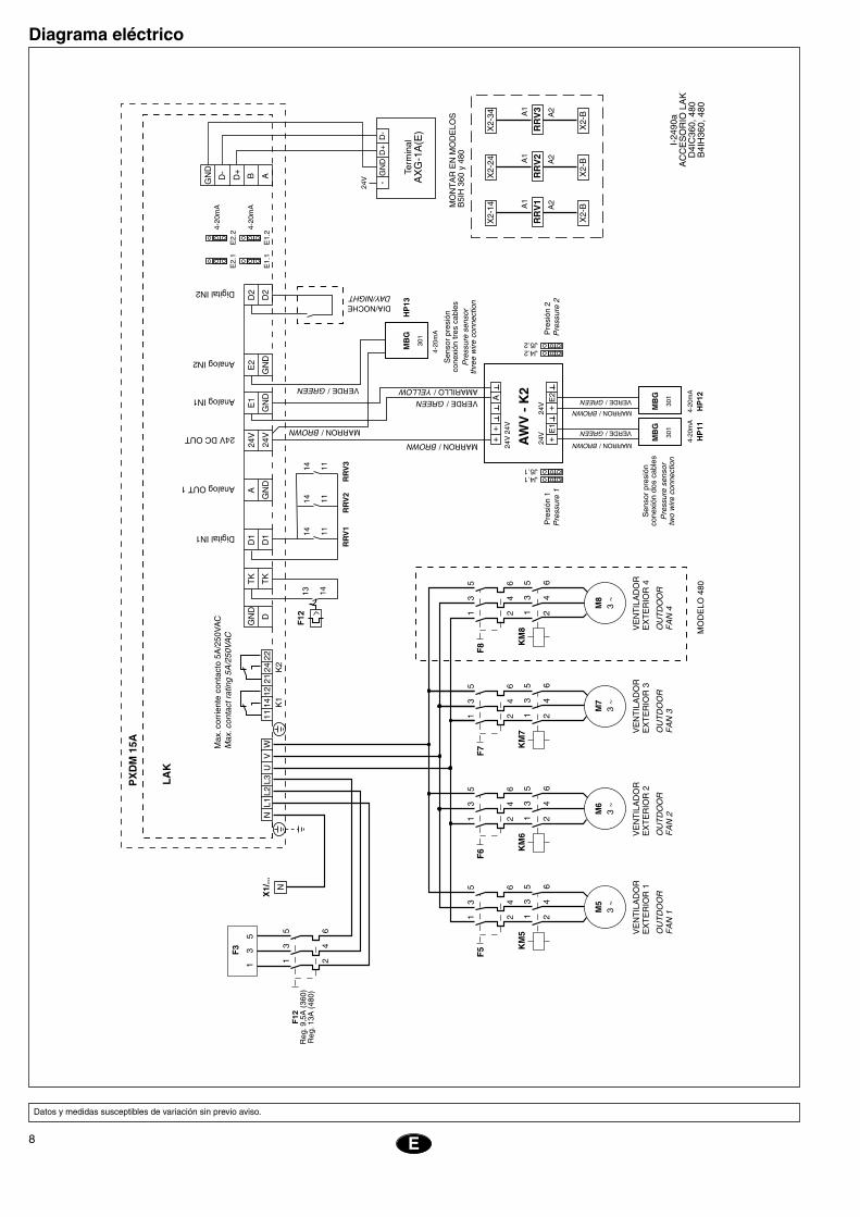
Diagrama eléctrico
Datos y medidas susceptibles de variación sin previo aviso.
����
���
���������
����
���
���
����
�����
���
����
��
��
�
��
���
���
�����
�����
�����
�����
����
��
��
�
��
�
���
����
��
�
��
���
������
����
�������
���
�������
������ �
��
��
��
�
��
��
�
��
�
��
���
������
����
�������
���
�������
������ �
��
��
��
�
��
��
�
��
�
��
���
������
����
�������
���
�������
������ �
��
��
��
�
��
��
�
��
�
��
���
������
����
�������
���
�������
������ �
��
��
��
�
��
��
�
��
�
������
����
����
����
�����
���
�
����
��
��
��
���
��� �
��������
���
�����
����
���
������
��
�����������
������������
����������
����������
����������
�����������
��������������
�������������
��������������
�������������
������������������
���
����
����
����
����
������
����
�������
��
�����
�
���
������
�����
����
����
����
����
���
���
����
����
����
����
����
����
�������
��������������
�������������
��������������
�������������
���
���
���
���
���
���
����
��
���
����
�����
����
���
���
����
�����
����
���
��������
��������
��
�
���
���
���
���
����
��
����
����
���
������
�����
����
����
�����
����
���
�����������������
����
���
�� ��
��
���
�
����
���
��
���
���
��
����
���
��
���
���
��
����
����
����
�
���
���
����
����
��
��
�� ��
����
���
��
��
���
��
��
�
���
���
���
��
���
��
���
��
��
���
�����
�����
����
����
����
���
����
��
�����
����
������
����
����
����
�
���
�
���
�
���
�
���
�
���
����
��
����
��
�� ��
����
�� ��
����
�� ��
����
���
���
����
��
����
9
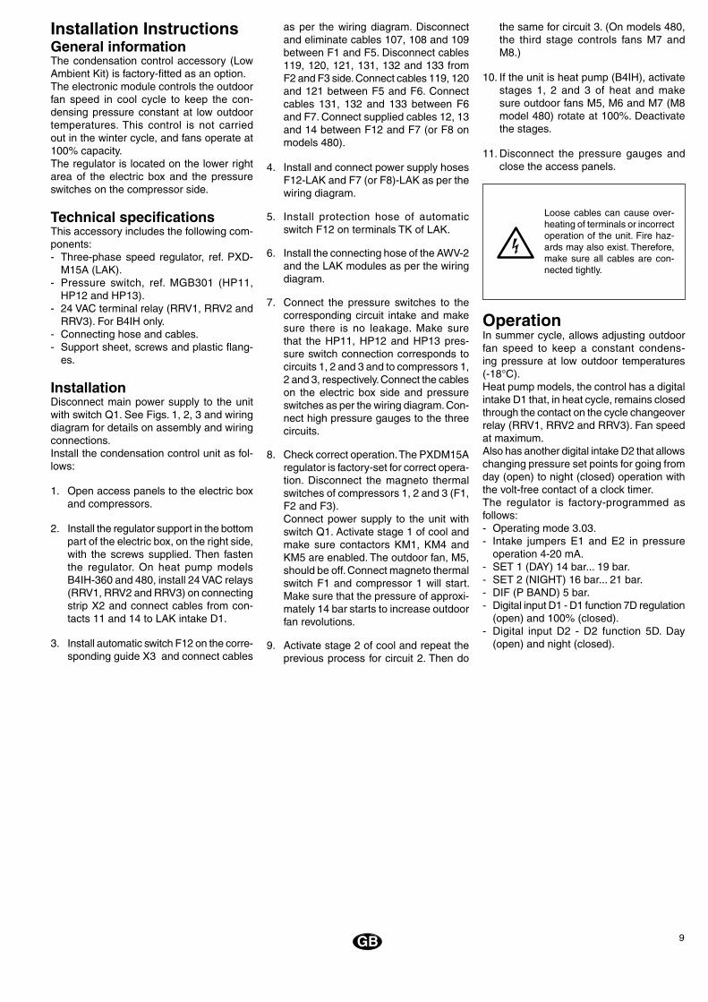
Installation InstructionsGeneral informationThe condensation control accessory (Low Ambient Kit) is factory-fitted as an option.The electronic module controls the outdoor fan speed in cool cycle to keep the con-densing pressure constant at low outdoor temperatures. This control is not carried out in the winter cycle, and fans operate at 100% capacity.The regulator is located on the lower right area of the electric box and the pressure switches on the compressor side.
Technical specificationsThis accessory includes the following com-ponents:- Three-phase speed regulator, ref. PXD-
M15A (LAK).- Pressure switch, ref. MGB301 (HP11,
HP12 and HP13).- 24 VAC terminal relay (RRV1, RRV2 and
RRV3). For B4IH only.- Connecting hose and cables.- Support sheet, screws and plastic flang-
es.
InstallationDisconnect main power supply to the unit with switch Q1. See Figs. 1, 2, 3 and wiring diagram for details on assembly and wiring connections.Install the condensation control unit as fol-lows:
1. Open access panels to the electric box and compressors.
2. Install the regulator support in the bottom part of the electric box, on the right side, with the screws supplied. Then fasten the regulator. On heat pump models B4IH-360 and 480, install 24 VAC relays (RRV1, RRV2 and RRV3) on connecting strip X2 and connect cables from con-tacts 11 and 14 to LAK intake D1.
3. Install automatic switch F12 on the corre-sponding guide X3 and connect cables
as per the wiring diagram. Disconnect and eliminate cables 107, 108 and 109 between F1 and F5. Disconnect cables 119, 120, 121, 131, 132 and 133 from F2 and F3 side. Connect cables 119, 120 and 121 between F5 and F6. Connect cables 131, 132 and 133 between F6 and F7. Connect supplied cables 12, 13 and 14 between F12 and F7 (or F8 on models 480).
4. Install and connect power supply hoses F12-LAK and F7 (or F8)-LAK as per the wiring diagram.
5. Install protection hose of automatic switch F12 on terminals TK of LAK.
6. Install the connecting hose of the AWV-2 and the LAK modules as per the wiring diagram.
7. Connect the pressure switches to the corresponding circuit intake and make sure there is no leakage. Make sure that the HP11, HP12 and HP13 pres-sure switch connection corresponds to circuits 1, 2 and 3 and to compressors 1, 2 and 3, respectively. Connect the cables on the electric box side and pressure switches as per the wiring diagram. Con-nect high pressure gauges to the three circuits.
8. Check correct operation. The PXDM15A regulator is factory-set for correct opera-tion. Disconnect the magneto thermal switches of compressors 1, 2 and 3 (F1, F2 and F3).
Connect power supply to the unit with switch Q1. Activate stage 1 of cool and make sure contactors KM1, KM4 and KM5 are enabled. The outdoor fan, M5, should be off. Connect magneto thermal switch F1 and compressor 1 will start. Make sure that the pressure of approxi-mately 14 bar starts to increase outdoor fan revolutions.
9. Activate stage 2 of cool and repeat the previous process for circuit 2. Then do
the same for circuit 3. (On models 480, the third stage controls fans M7 and M8.)
10. If the unit is heat pump (B4IH), activate stages 1, 2 and 3 of heat and make sure outdoor fans M5, M6 and M7 (M8 model 480) rotate at 100%. Deactivate the stages.
11. Disconnect the pressure gauges and close the access panels.
Loose cables can cause over-heating of terminals or incorrect operation of the unit. Fire haz-ards may also exist. Therefore, make sure all cables are con-nected tightly.
OperationIn summer cycle, allows adjusting outdoor fan speed to keep a constant condens-ing pressure at low outdoor temperatures (-18°C). Heat pump models, the control has a digital intake D1 that, in heat cycle, remains closed through the contact on the cycle changeover relay (RRV1, RRV2 and RRV3). Fan speed at maximum.Also has another digital intake D2 that allows changing pressure set points for going from day (open) to night (closed) operation with the volt-free contact of a clock timer.The regulator is factory-programmed as follows:- Operating mode 3.03.- Intake jumpers E1 and E2 in pressure
operation 4-20 mA.- SET 1 (DAY) 14 bar... 19 bar.- SET 2 (NIGHT) 16 bar... 21 bar.- DIF (P BAND) 5 bar.- Digital input D1 - D1 function 7D regulation
(open) and 100% (closed).- Digital input D2 - D2 function 5D. Day
(open) and night (closed).
GB

10
Wiring diagram
Data and dimensions subject to change without prior notice.
GB
����
���
�����
��������
���
���
����
�����
���
����
��
��
�
��
���
���
�����
�����
�����
�����
����
��
��
�
��
�
���
����
��
�
��
���
������
����
�������
���
�������
������ �
��
��
��
�
��
��
�
��
�
��
���
������
����
�������
���
�������
������ �
��
��
��
�
��
��
�
��
�
��
���
������
����
�������
���
�������
������ �
��
��
��
�
��
��
�
��
�
��
���
������
����
�������
���
�������
������ �
��
��
��
�
��
��
�
��
�
������
����
����
����
�����
���
�
����
��
��
��
���
��� �
�����
����
���
�����
���
���
����
����
��
�����������
������������
����������
����������
����������
�����������
��������������
�������������
��������������
�������������
������������������
���
����
����
����
����
������
����
�������
��
�����
�
���
������
�����
����
����
����
����
���
���
����
����
����
����
����
����
�������
��������������
�������������
��������������
�������������
���
���
���
���
���
���
����
��
���
����
�����
����
���
���
����
�����
����
���
��������
��������
��
�
���
���
���
���
����
��
����
����
���
������
�����
����
����
�����
����
���
�����������������
����
���
�� ��
��
���
�
����
���
��
���
���
��
����
���
��
���
���
��
����
����
����
�
���
���
����
����
��
��
�� ��
����
���
��
��
���
��
��
�
���
���
���
��
���
��
���
��
��
���
�����
�����
����
����
����
���
����
��
�����
����
������
����
����
����
�
���
�
���
�
���
�
���
�
���
����
��
����
��
�� ��
����
�� ��
����
�� ��
����
���
���
����
��
����
11F
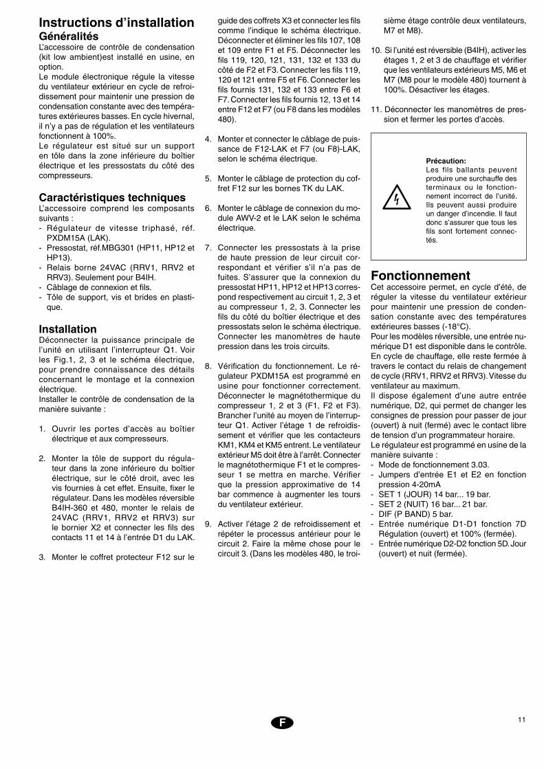
Instructions d’installationGénéralitésL’accessoire de contrôle de condensation (kit low ambient)est installé en usine, en option.Le module électronique régule la vitesse du ventilateur extérieur en cycle de refroi-dissement pour maintenir une pression de condensation constante avec des tempéra-tures extérieures basses. En cycle hivernal, il n’y a pas de régulation et les ventilateurs fonctionnent à 100%.Le régulateur est situé sur un support en tôle dans la zone inférieure du boîtier électrique et les pressostats du côté des compresseurs.
Caractéristiques techniquesL’accessoire comprend les composants suivants :- Régulateur de vitesse triphasé, réf.
PXDM15A (LAK).- Pressostat, réf.MBG301 (HP11, HP12 et
HP13).- Relais borne 24VAC (RRV1, RRV2 et
RRV3). Seulement pour B4IH.- Câblage de connexion et fils.- Tôle de support, vis et brides en plasti-
que.
InstallationDéconnecter la puissance principale de l’unité en utilisant l’interrupteur Q1. Voir les Fig.1, 2, 3 et le schéma électrique, pour prendre connaissance des détails concernant le montage et la connexion électrique.Installer le contrôle de condensation de la manière suivante :
1. Ouvrir les portes d’accès au boîtier électrique et aux compresseurs.
2. Monter la tôle de support du régula-teur dans la zone inférieure du boîtier électrique, sur le côté droit, avec les vis fournies à cet effet. Ensuite, fixer le régulateur. Dans les modèles réversible B4IH-360 et 480, monter le relais de 24VAC (RRV1, RRV2 et RRV3) sur le bornier X2 et connecter les fils des contacts 11 et 14 à l’entrée D1 du LAK.
3. Monter le coffret protecteur F12 sur le
guide des coffrets X3 et connecter les fils comme l’indique le schéma électrique. Déconnecter et éliminer les fils 107, 108 et 109 entre F1 et F5. Déconnecter les fils 119, 120, 121, 131, 132 et 133 du côté de F2 et F3. Connecter les fils 119, 120 et 121 entre F5 et F6. Connecter les fils fournis 131, 132 et 133 entre F6 et F7. Connecter les fils fournis 12, 13 et 14 entre F12 et F7 (ou F8 dans les modèles 480).
4. Monter et connecter le câblage de puis-sance de F12-LAK et F7 (ou F8)-LAK, selon le schéma électrique.
5. Monter le câblage de protection du cof-fret F12 sur les bornes TK du LAK.
6. Monter le câblage de connexion du mo-dule AWV-2 et le LAK selon le schéma électrique.
7. Connecter les pressostats à la prise de haute pression de leur circuit cor-respondant et vérifier s’il n’a pas de fuites. S’assurer que la connexion du pressostat HP11, HP12 et HP13 corres-pond respectivement au circuit 1, 2, 3 et au compresseur 1, 2, 3. Connecter les fils du côté du boîtier électrique et des pressostats selon le schéma électrique. Connecter les manomètres de haute pression dans les trois circuits.
8. Vérification du fonctionnement. Le ré-gulateur PXDM15A est programmé en usine pour fonctionner correctement. Déconnecter le magnétothermique du compresseur 1, 2 et 3 (F1, F2 et F3). Brancher l’unité au moyen de l’interrup-teur Q1. Activer l’étage 1 de refroidis-sement et vérifier que les contacteurs KM1, KM4 et KM5 entrent. Le ventilateur extérieur M5 doit être à l’arrêt. Connecter le magnétothermique F1 et le compres-seur 1 se mettra en marche. Vérifier que la pression approximative de 14 bar commence à augmenter les tours du ventilateur extérieur.
9. Activer l’étage 2 de refroidissement et répéter le processus antérieur pour le circuit 2. Faire la même chose pour le circuit 3. (Dans les modèles 480, le troi-
sième étage contrôle deux ventilateurs, M7 et M8).
10. Si l’unité est réversible (B4IH), activer les étages 1, 2 et 3 de chauffage et vérifier que les ventilateurs extérieurs M5, M6 et M7 (M8 pour le modèle 480) tournent à 100%. Désactiver les étages.
11. Déconnecter les manomètres de pres-sion et fermer les portes d’accès.
Précaution:Les fils ballants peuvent produire une surchauffe des terminaux ou le fonction-nement incorrect de l’unité. Ils peuvent aussi produire un danger d’incendie. Il faut donc s’assurer que tous les fils sont fortement connec-tés.
FonctionnementCet accessoire permet, en cycle d’été, de réguler la vitesse du ventilateur extérieur pour maintenir une pression de conden-sation constante avec des températures extérieures basses (-18°C).Pour les modèles réversible, une entrée nu-mérique D1 est disponible dans le contrôle. En cycle de chauffage, elle reste fermée à travers le contact du relais de changement de cycle (RRV1, RRV2 et RRV3). Vitesse du ventilateur au maximum.Il dispose également d’une autre entrée numérique, D2, qui permet de changer les consignes de pression pour passer de jour (ouvert) à nuit (fermé) avec le contact libre de tension d’un programmateur horaire.Le régulateur est programmé en usine de la manière suivante :- Mode de fonctionnement 3.03.- Jumpers d’entrée E1 et E2 en fonction
pression 4-20mA- SET 1 (JOUR) 14 bar... 19 bar.- SET 2 (NUIT) 16 bar... 21 bar.- DIF (P BAND) 5 bar.- Entrée numérique D1-D1 fonction 7D
Régulation (ouvert) et 100% (fermée).- Entrée numérique D2-D2 fonction 5D. Jour
(ouvert) et nuit (fermée).
12 F
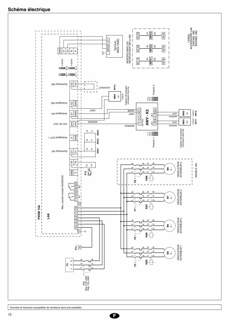
Schéma électrique
Données et mesures susceptibles de variations sans avis préalable.
����
���
���������
���
��
���
���
����
�����
���
����
��
��
�
��
���
���
�����
�����
�����
�����
����
��
��
�
��
�
��
���
�����
����
��
�������
����
� �
��
��
��
�
��
��
�
��
�
��
���
�����
����
��
�������
����
� �
��
��
��
�
��
��
�
��
�
��
���
�����
����
��
�������
����
� �
��
��
��
�
��
��
�
��
�
��
���
�����
����
��
�������
����
� �
��
��
��
�
��
��
�
��
�
������
����
����
����
�����
���
�
��������
�����
��
������
���
�����
����
�����
�������������
����������������
����������
��������������
��������������
�������������
������
����
������
����
���������
��
�����
�
���
����
����
����
����
����
������
����
�����
������
����
������
����
���
����
����
����
����
����
������
����������
�����
����
���
�� ��
��
���
�
����
���
��
���
���
��
����
���
��
���
���
��
����
����
����
�
���
���
����
����
��
��
�� ��
����
���
��
��
���
��
��
�
���
���
���
��
���
��
���
��
��
���
�����
����
����
������
���
����
�
���
�
���
�
���
�
���
�
���
����
��
����
��
�� ��
����
�� ��
����
�� ��
����
���
���
����
��
����
���
����
��
�
����
��
��
��
���
��� �
���
���
���
���
���
���
����
��
���
������
����
������
�
��������
��������
��
�
���
���
���
���
����
��
����
����
13P
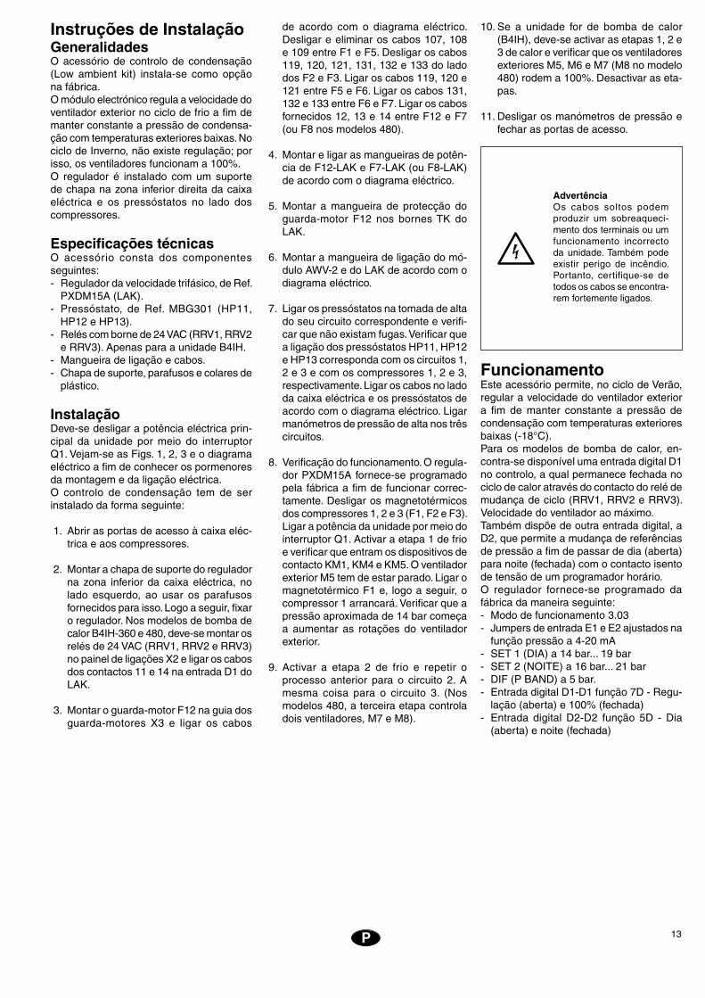
Instruções de InstalaçãoGeneralidadesO acessório de controlo de condensação (Low ambient kit) instala-se como opção na fábrica.O módulo electrónico regula a velocidade do ventilador exterior no ciclo de frio a fim de manter constante a pressão de condensa-ção com temperaturas exteriores baixas. No ciclo de Inverno, não existe regulação; por isso, os ventiladores funcionam a 100%.O regulador é instalado com um suporte de chapa na zona inferior direita da caixa eléctrica e os pressóstatos no lado dos compressores.
Especificações técnicasO acessório consta dos componentes seguintes:- Regulador da velocidade trifásico, de Ref.
PXDM15A (LAK).- Pressóstato, de Ref. MBG301 (HP11,
HP12 e HP13).- Relés com borne de 24 VAC (RRV1, RRV2
e RRV3). Apenas para a unidade B4IH.- Mangueira de ligação e cabos.- Chapa de suporte, parafusos e colares de
plástico.
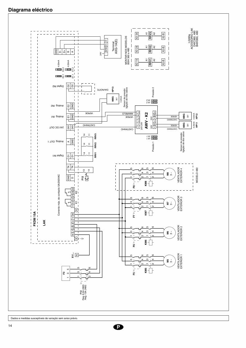
InstalaçãoDeve-se desligar a potência eléctrica prin-cipal da unidade por meio do interruptor Q1. Vejam-se as Figs. 1, 2, 3 e o diagrama eléctrico a fim de conhecer os pormenores da montagem e da ligação eléctrica.O controlo de condensação tem de ser instalado da forma seguinte:
1. Abrir as portas de acesso à caixa eléc-trica e aos compressores.
2. Montar a chapa de suporte do regulador na zona inferior da caixa eléctrica, no lado esquerdo, ao usar os parafusos fornecidos para isso. Logo a seguir, fixar o regulador. Nos modelos de bomba de calor B4IH-360 e 480, deve-se montar os relés de 24 VAC (RRV1, RRV2 e RRV3) no painel de ligações X2 e ligar os cabos dos contactos 11 e 14 na entrada D1 do LAK.
3. Montar o guarda-motor F12 na guia dos guarda-motores X3 e ligar os cabos
de acordo com o diagrama eléctrico. Desligar e eliminar os cabos 107, 108 e 109 entre F1 e F5. Desligar os cabos 119, 120, 121, 131, 132 e 133 do lado dos F2 e F3. Ligar os cabos 119, 120 e 121 entre F5 e F6. Ligar os cabos 131, 132 e 133 entre F6 e F7. Ligar os cabos fornecidos 12, 13 e 14 entre F12 e F7 (ou F8 nos modelos 480).
4. Montar e ligar as mangueiras de potên-cia de F12-LAK e F7-LAK (ou F8-LAK) de acordo com o diagrama eléctrico.
5. Montar a mangueira de protecção do guarda-motor F12 nos bornes TK do LAK.
6. Montar a mangueira de ligação do mó-dulo AWV-2 e do LAK de acordo com o diagrama eléctrico.
7. Ligar os pressóstatos na tomada de alta do seu circuito correspondente e verifi-car que não existam fugas. Verificar que a ligação dos pressóstatos HP11, HP12 e HP13 corresponda com os circuitos 1, 2 e 3 e com os compressores 1, 2 e 3, respectivamente. Ligar os cabos no lado da caixa eléctrica e os pressóstatos de acordo com o diagrama eléctrico. Ligar manómetros de pressão de alta nos três circuitos.
8. Verificação do funcionamento. O regula-dor PXDM15A fornece-se programado pela fábrica a fim de funcionar correc-tamente. Desligar os magnetotérmicos dos compressores 1, 2 e 3 (F1, F2 e F3). Ligar a potência da unidade por meio do interruptor Q1. Activar a etapa 1 de frio e verificar que entram os dispositivos de contacto KM1, KM4 e KM5. O ventilador exterior M5 tem de estar parado. Ligar o magnetotérmico F1 e, logo a seguir, o compressor 1 arrancará. Verificar que a pressão aproximada de 14 bar começa a aumentar as rotações do ventilador exterior.
9. Activar a etapa 2 de frio e repetir o processo anterior para o circuito 2. A mesma coisa para o circuito 3. (Nos modelos 480, a terceira etapa controla dois ventiladores, M7 e M8).
10. Se a unidade for de bomba de calor (B4IH), deve-se activar as etapas 1, 2 e 3 de calor e verificar que os ventiladores exteriores M5, M6 e M7 (M8 no modelo 480) rodem a 100%. Desactivar as eta-pas.
11. Desligar os manómetros de pressão e fechar as portas de acesso.
AdvertênciaOs cabos soltos podem produzir um sobreaqueci-mento dos terminais ou um funcionamento incorrecto da unidade. Também pode existir perigo de incêndio. Portanto, certifique-se de todos os cabos se encontra-rem fortemente ligados.
FuncionamentoEste acessório permite, no ciclo de Verão, regular a velocidade do ventilador exterior a fim de manter constante a pressão de condensação com temperaturas exteriores baixas (-18°C).Para os modelos de bomba de calor, en-contra-se disponível uma entrada digital D1 no controlo, a qual permanece fechada no ciclo de calor através do contacto do relé de mudança de ciclo (RRV1, RRV2 e RRV3). Velocidade do ventilador ao máximo.Também dispõe de outra entrada digital, a D2, que permite a mudança de referências de pressão a fim de passar de dia (aberta) para noite (fechada) com o contacto isento de tensão de um programador horário.O regulador fornece-se programado da fábrica da maneira seguinte:- Modo de funcionamento 3.03- Jumpers de entrada E1 e E2 ajustados na
função pressão a 4-20 mA- SET 1 (DIA) a 14 bar... 19 bar- SET 2 (NOITE) a 16 bar... 21 bar- DIF (P BAND) a 5 bar.- Entrada digital D1-D1 função 7D - Regu-
lação (aberta) e 100% (fechada)- Entrada digital D2-D2 função 5D - Dia
(aberta) e noite (fechada)
14 P
Diagrama eléctrico
Dados e medidas susceptíveis de variação sem aviso prévio.
����
���
���������
����
���
���
����
�����
���
����
��
��
�
��
���
���
�����
�����
�����
�����
����
��
��
�
��
�
��
���
������
����
�������
���
� �
��
��
��
�
��
��
�
��
�
��
���
������
����
�������
���
� �
��
��
��
�
��
��
�
��
�
��
���
������
����
�������
���
� �
��
��
��
�
��
��
�
��
�
��
���
������
����
�������
���
� �
��
��
��
�
��
��
�
��
�
������
����
����
����
�����
���
�
�����
���
����
�����
����
���
����
����
�����������
�������������
����������
�����������
�����������
�����������
��������
�����
��������
�����
���������
��
�����
�
���
������
����
����
�����
����
����
����
���
��������
�����
��������
�����
���
������
����
����
�����
����
������
����
��
�������
����
���
�� ��
��
���
�
����
���
��
���
���
��
����
���
��
���
���
��
����
����
����
�
���
���
����
����
��
��
�� ��
����
���
��
��
���
��
��
�
���
���
���
��
���
��
���
��
��
���
����
���
�����
����
����
����
���
����
�
���
�
���
�
���
�
���
�
���
����
��
����
��
�� ��
����
�� ��
����
�� ��
����
���
���
����
��
����
���
����
��
�
����
��
��
��
���
��� �
���
���
���
���
���
���
����
��
���
����
�����
����
��
��������
��������
��
�
���
���
���
���
����
��
����
����
15IT
Istruzioni per l’installazio-neGeneralitàIl Kit Low Ambient è un accessorio per il con-trollo della pressione di condensazione che viene montato come optional in fabbrica.Il modulo elettronico regola la velocità del ventilatore esterno nel ciclo estivo (raffresca-mento) per mantenere costante la pressione di condensazione con temperature esterne basse.Nel ciclo invernale (riscaldamento) non c’è regolazione, e i ventilatori funzionano al 100%.Il regolatore è fissato con un supporto di lamiera nella zona inferiore destra del quadro elettrico e i pressostati nel lato dei compressori.
Caratteristiche tecnicheL’optional comprende i seguenti elementi:- Regolatore di velocità trifase, cod. PXD-
M15A (LAK).- Pressostati, cod. MBG301 (HP11, HP12
e HP13).- Relè morsetto a 24 V c.a. (RRV1, RRV2
e RRV3). Solo B4IH.- Cavi per l’allacciamento e i collegamen-
ti.- Guida DIN, viti, guide passanti e fascette
di plastica.
InstallazioneScollegare l’unità dalla rete elettrica genera-le attraverso l’interruttore Q1. Per i dettagli della connessione, vedere le Figg. 1, 2, 3 e lo schema elettrico.Installare il controllo della pressione di con-densazione, procedendo come segue:
1. Aprire le porte d’accesso al quadro elettrico e ai compressori.
2. Con le viti fornite, montare la lamiera di supporto del regolatore nella zona infe-riore del quadro elettrico, sul lato destro. Quindi, fissare il regolatore. Nei modelli a pompa di calore (B4IH-360 e 480) montare i relè a 24 V c.a. (RRV1, RRV2 e RRV3) nella morsettiera X2 e collegare i cavi dei contatti 11 e 14 all’ingresso D1 del LAK.
3. Montare il salvamotore F12 nella guida
dei salvamotori X3 e collegare i cavi come indicato nello schema elettrico. Scollegare ed eliminare i cavi 107, 108 e 109 tra F1 ed F5. Scollegare i cavi 119, 120, 121, 131, 132 e 133 nel lato F2 ed F3. Collegare i cavi 119, 120 e 121 tra F5 ed F6. Collegare i cavi 131, 132 e 133 tra F6 ed F7. Collegare i cavi forniti (12, 13 e 14) tra F12 ed F7 (o F8 nei modelli 480).
4. Montare e collegare i cavi di potenza di F12-LAK ed F7 (o F8)-LAK come indi-cato nello schema elettrico.
5. Montare il cavo di protezione del salva-motore F12 ai morsetti TK del LAK.
6. Montare il cavo di collegamento del modulo AWV-2 e del LAK come indicato nello schema elettrico.
7. Collegare i pressostati alla presa di alta del circuito corrispondente e accertarsi che non ci siano fughe. Controllare che i collegamenti del pressostato HP11, HP12 e HP13 corrispondano ai circuiti 1, 2 e 3 e ai compressori 1, 2 e 3, ri-spettivamente. Collegare i cavi nel lato del quadro elettrico e dei pressostati, come indicato nello schema elettrico. Collegare i manometri della pressione di alta ai tre circuiti.
8. Effettuare un controllo del funziona-mento. Il regolatore PXDM15A è già programmato di fabbrica per funzionare correttamente. Scollegare l’interruttore termomagnetico del compressore 1, 2 e 3 (F1, F2 ed F3). Collegare l’alimen-tazione elettrica dell’unità attraverso l’interruttore Q1. Attivare lo stadio 1 di raffrescamento e controllare l’attivazione dei contattori KM1, KM4 e KM5. Il ven-tilatore esterno M5 deve essere fermo. Collegare l’interruttore termomagnetico F1 e avviare il compressore 1. Verificare che, con una pressione approssimativa di 14 bar, il regime di rotazione del ven-tilatore esterno inizia ad aumentare.
9. Attivare lo stadio 2 di raffrescamento e ripetere il processo appena descritto per il circuito 2. Fare lo stesso per il circuito 3. (Nel modello 480, il terzo stadio controlla due ventilatori: M7 ed M8)
10. Se l’unità è a pompa di calore (B4IH), at-
tivare gli stadi 1, 2 e 3 di riscaldamento e verificare che i ventilatori esterni M5, M6 ed M7 (M8 nel modello 480) girino al 100%. Disattivare gli stadi.
11. Scollegare i manometri e chiudere le porte d’accesso.
Attenzione
I cavi lenti possono occasio-nare un surriscaldamento dei morsetti o un cattivo funzio-namento dell’unità, oltre a costituire un potenziale pe-ricolo d’incendio. Accertarsi, pertanto, che tutti i cavi siano ben collegati.
FunzionamentoNel ciclo estivo, permette di regolare la ve-locità del ventilatore esterno per mantenere costante la pressione di condensazione con temperature esterne basse (-18 °C).Per i modelli a pompa di calore è disponibile nel controllo un ingresso digitale D1 che, nel ciclo di riscaldamento, rimane chiuso attraverso il contatto del relè di cambio di ciclo (RRV1, RRV2 e RRV3). Velocità del ventilatore al massimo.È anche disponibile un altro ingresso digitale D2, che permette il cambio dei set point della pressione per passare dal programma diur-no (aperto) al programma notturno (chiuso) mediante il contatto privo di tensione di un programmatore orario.Il regolatore viene programmato di fabbri-ca:- Modo di funzionamento 3.03- Jumper E1 ed E2 in funzione della pres-
sione 4-20 mA- Set point 1 (giorno): 14...19 bar- Set point 2 (notte): 16...21 bar- Differenziale (P Band): 5 bar- Ingresso digitale D1-D1 funzione 7D. Re-
golazione: 0% (aperto) e 100% (chiuso)- Ingresso digitale D2-D2 funzione 5D:
Giorno (aperto) e notte (chiuso)

16 IT
Schema elettrico
Dati e misure soggetti a variazioni senza preavviso
����
���
����������
����
���
���
����
�����
���
����
��
��
�
��
���
���
�����
�����
�����
�����
����
��
��
�
��
�
��
���
������
���
��
���������
� �
��
��
��
�
��
��
�
��
�
��
���
������
���
��
���������
� �
��
��
��
�
��
��
�
��
�
��
���
������
���
��
���������
� �
��
��
��
�
��
��
�
��
�
��
���
������
���
��
���������
� �
��
��
��
�
��
��
�
��
�
������
���
��
���
�����
�����
���
�
����
����
����
����
�����
����
���
����
����
������������
���������������
����������
�������������
�������������
������������
�������
�����
�������
�����
������������
��
�����
�
���
����
�����
����
����
����
������
����
����
����
�������
�����
�������
�����
���
����
�����
����
����
����
������
����
����
����
������
����
���
�� ��
��
���
�
����
���
��
���
���
��
����
���
��
���
���
��
����
����
����
�
���
���
����
����
��
��
�� ��
����
���
��
��
���
��
��
�
���
���
���
��
���
��
���
��
��
���
����
���
�����
����
�����
���
�������
�
���
�
���
�
���
�
���
�
���
����
��
����
��
�� ��
����
�� ��
����
�� ��
����
���
���
����
��
����
���
����
��
�
����
��
��
��
���
��� �
���
���
���
���
���
���
����
��
���
������
�����
������
��
��������
��������
��
�
���
���
���
���
����
��
����
����
17D
Hinweise zum EinbauAllgemeine AngabenDie als Zubehör lieferbare Kondensations-druckkontrolle (Low Ambient Kit) wird als Option im Werk eingebaut.Das Elektronikmodul regelt die Geschwin-digkeit des Außenventilators bei Kühlbetrieb zur Aufrechterhaltung eines konstanten Kondensationsdrucks bei niedrigen Außen-temperaturen. Im Winterbetrieb arbeiten die Ventilatoren zu 100% und es entfällt jede Regelung der Geschwindigkeit.Der Regler wird im elektrischen Schaltkas-ten untergebracht, die Druckwächter neben den Verdichtern.
Technische SpezifikationenDas Zubehörteil umfasst die folgenden Einzelkomponenten:- Drehstrom-Geschwindigkeitsregler Best.-
Nr. PXDM15A (LAK).- Druckwächter Best.-Nr. MBG301 (HP11,
HP12 und HP13).- Klemmenrelais 24 V~ (RRV1, RRV2 und
RRV 3). Nur für B4IH.- Anschlussleitung und Kabel.- Halteblech, Schrauben und Kunststoffla-
schen.
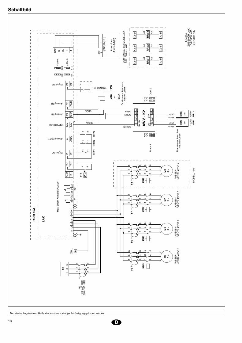
EinbauAnlage über den Hauptschalter Q1 vom Netz trennen. Zum Einbau und zur elektrischen Verkabelung siehe die Fig. 1, 2, 3 und das entsprechende Schaltbild.Kondensationskontrolle wie folgt einbauen:1. Zugang zum elektrischem Schaltkasten
und zu den Verdichtern entfernen.
2. Halteblech für den Regler mit den bei-liegenden Schrauben unten rechts im elektrischen Schaltkasten einbauen. Anschließend Regler befestigen. Bei den Wärmepumpenmodellen B4IH-360 und 480 auch die 24-V-Wechselstrom-Relais (RRV1, RRV2 und RRV3) über Klemmenleiste X2 installieren und die Leiter der Kontakte 11 und 14 an den Eingang D1 am LAK legen.
3. Motorschutzschalter F12 in die Führung der Motorschutzschalter X3 einbauen und Leiter wie im Schaltbild gezeigt anschließen. Leiter 107, 108 und 109 zwischen F1 und F5 abklemmen und entfernen. Leiter 119, 120, 121, 131, 132 und 133 neben F2 und F3 abklemmen.
Leiter 119, 120 und 121 zwischen F5 und F6 legen. Leiter 131, 132 und 133 zwischen F6 und F7 legen. Die beilie-genden Leiter 12, 13 und 14 zwischen F12 und F7 (bzw. F8 bei den Baugrößen 480) legen.
4. Versorgungsleitungen für F12-LAK und F7 (bzw. F8)-LAK wie im Schaltbild ge-zeigt verlegen und anschließen.
5. Leitung des Motorschutzschalters F12 an Klemme TK am LAK legen.
6. Anschlussleitung des Moduls AWV-2 und LAK wie im Schaltbild gezeigt anschlie-ßen.
7. Druckwächter an der Hochdruckabnah-me des entsprechenden Kreislaufs an-schließen und darauf achten, dass keine Leckagen auftreten. Sicherstellen, dass der Anschluss der Druckwächter HP11, HP12 und HP13 dem Kreislauf 1, 2 und 3 und dem Verdichter 1, 2 und 3 entspricht. Leiter im elektrischen Schaltkasten und Druckwächter wie im Schaltbild gezeigt anschließen. An die drei Kreisläufe Hochdruckmanometer legen.
8. Korrekten Betrieb überprüfen. Der Reg-ler PXDM15A wird bereits im Werk für einen korrekten Betrieb eingestellt. Ther-momagnetsicherung der Verdichter 1, 2 und 3 (F1, F2, F3) abschalten. Anlage über den Hauptschalter Q1 wieder unter Strom setzen. Kühlstufe 1 aktivieren und sicherstellen, dass die Schaltschütze KM1, KM4 und KM5 ansprechen. Der Außenventilator M5 darf nicht arbeiten. Thermomagnetsicherung F1 einschal-ten, worauf sich der Verdichter 1 in Gang setzt. Der Druck von ungefähr 14 bar muss nun nach und nach die Dreh-geschwindigkeit des Außenventilators steigern.
9. Kühlstufe 2 aktivieren und obiges Ver-fahren für den Kreislauf 2 wiederholen. Ebenso dann für den Kreislauf 3. (Bei den Geräten der Baugröße 480 kontrol-liert die dritte Stufe die beiden Ventila-toren M7 und M8.)
10. Bei Wärmepumpenmodellen (B4IH) die Heizstufen 1, 2 und 3 aktivieren und überprüfen, dass die Außenventilatoren
M5, M6 und M7 (M8 bei Baugröße 480) zu 100% laufen. Heizstufen wieder ausschalten.
11. Druckmanometer entfernen und ein-gangs abgenommene Zugänge wieder anbauen.
Vorsicht:Locker sitzende Kabel können zu einer Überhitzung der Klem-men oder einem fehlerhaften Betrieb der Anlage führen. Fer-ner besteht auch ein konkretes Brandrisiko. Alle Leitungskabel sind deshalb sorgfältig anzu-schließen.
BetriebErlaubt eine Regelung der Geschwindigkeit des Außenventilators bei Kühlbetrieb zur Aufrechterhaltung eines konstanten Kon-densationsdrucks bei niedrigen Außentem-peraturen (-18 °C). Für Wärmepumpenmodelle verfügt die Kon-trolle über einen Digitaleingang D1, der bei Heizbetrieb über den Kontakt des Relais zur Betriebsumkehr (RRV1, RRV2 und RRV3) geschlossen bleibt. Ventilatorgeschwindig-keit auf maximalem Wert.Vorgesehen ist ferner ein zweiter Digitalein-gang D2, über den eine Veränderung des Solldruckwerts möglich ist, sodass über den spannungsfreien Kontakt einer Zeit-kontrolle vom Betrieb tagsüber (offen) auf Nachtbetrieb (geschlossen) übergegangen werden kann.Der Regler wird im Werk wie folgt program-miert:- Betriebsweise 3.03.- Eingangsbrücken E1 und E2 je nach
Druck 4-20 mA.- SET 1 (TAGSÜBER) 14 bar ... 19 bar.- SET 2 (NACHTS) 16 bar ... 21 bar.- DIF (P BAND) 5 bar.- Digitaleingang D1-D1 Funktion 7D Rege-
lung (offen) und 100% (geschlossen).- Digitaleingang D2-D2 Funktion 5D. Tags-
über (offen) und nachts (geschlossen).
18 D
Schaltbild
Technische Angaben und Maße können ohne vorherige Ankündigung geändert werden.
����
���
���������
��
���
���
����
�����
���
����
��
��
�
��
���
���
�����
�����
�����
�����
����
��
��
�
��
�
��
���
�������
������
������
� �
��
��
��
�
��
��
�
��
�
��
���
�������
������
������
� �
��
��
��
�
��
��
�
��
�
��
���
�������
������
������
� �
��
��
��
�
��
��
�
��
�
��
���
�������
������
������
� �
��
��
��
�
��
��
�
��
�
������
����
���
������
�����
���
�
���
����
�����
����
�����
��
���
���
����
����
��
�����������
������������
����������
����������
����������
�����������
�����
����
�����
����
���������
��
�����
�
���
����
����
����
������
������
����
����
��
�����
����
�����
����
���
����
����
����
������
������
����
����
��
����
����
���
�� ��
��
���
�
����
���
��
���
���
��
����
���
��
���
���
��
����
����
����
�
���
���
����
����
��
��
�� ��
����
���
��
��
���
��
��
�
���
���
���
��
���
��
���
��
��
���
�������
����
������
���
����
���
�
���
�
���
�
���
�
���
����
��
����
��
�� ��
����
�� ��
����
�� ��
����
���
���
����
��
����
���
����
��
�
����
��
��
��
���
��� �
���
���
���
���
���
���
����
��
���
����
���
����
��������
��������
��
�
���
���
���
���
����
��
����
����
19NL
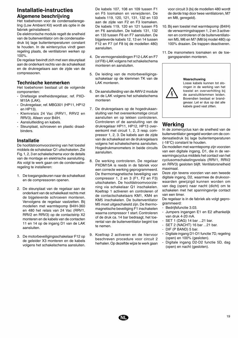
Installatie-instructiesAlgemene beschrijvingHet toebehoren voor de condensatierege-ling (Low Ambient Kit) wordt als optie in de fabriek geïnstalleerd.De elektronische module regelt de snelheid van de buitenventilator om de condensatie-druk bij lage buitentemperaturen constant te houden. In de wintercyclus vindt geen regeling plaats, de ventilatoren werken op 100%.De regelaar bevindt zich met een steunplaat aan de onderkant rechts van de schakelkast en de drukregelaars aan de zijde van de compressoren.
Technische kenmerkenHet toebehoren bestaat uit de volgende componenten:- Driefasige snelheidsregelaar, ref. PXD-
M15A (LAK).- Drukregelaar, ref. MBG301 (HP11, HP12
en HP13).- Klemrelais 24 Vac (RRV1, RRV2 en
RRV3). Alleen voor B4IH.- Aansluitleiding en kabels.- Steunplaat, schroeven en plastic draad-
binders.
InstallatieDe hoofdstroomvoorziening van het toestel middels de schakelaar Q1 uitschakelen. Zie Fig. 1, 2, 3 en schakelschema voor de details van de montage en elektrische aansluiting.Als volgt te werk gaan om de condensatie-regeling te installeren:
1. De toegangsdeuren naar de schakelkast en de compressoren openen.
2. De steunplaat van de regelaar aan de onderkant van de schakelkast rechts met de bijgeleverde schroeven monteren. Vervolgens de regelaar vastzetten. Bij modellen met warmtepomp B4IH-360 en 480 het relais van 24 Vac (RRV1, RRV2 en RRV3) op de contactstrip X2 monteren en de kabels van de contacten 11 en 14 op de ingang D1 van de LAK aansluiten.
3. De motorbeveiligingsschakelaar F12 op de geleider X3 monteren en de kabels volgens het schakelschema aansluiten.
De kabels 107, 108 en 109 tussen F1 en F5 losmaken en verwijderen. De kabels 119, 120, 121, 131, 132 en 133 aan de zijde van F2 en F3 losmaken. De kabels 119, 120 en 121 tussen F5 en F6 aansluiten. De kabels 131, 132 en 133 tussen F6 en F7 aansluiten. De bijgeleverde kabels 12, 13 en 14 tussen F12 en F7 (of F8 bij de modellen 480) aansluiten.
4. De vermogensleidingen F12-LAK en F7 (of F8)-LAK volgens het schakelschema monteren en aansluiten.
5. De leiding van de motorbeveiligings-schakelaar op de klemmen TK van de LAK monteren.
6. De aansluitleiding van de AWV-2 module en de LAK volgens het schakelschema monteren
7. De drukregelaars op de hogedrukaan-sluiting van het overeenkomstige circuit aansluiten en op lekken controleren. Controleren of de aansluiting van de drukregelaar HP11, HP12, HP13 over-eenkomt met circuit 1, 2, 3 resp. com-pressor 1, 2, 3. De kabels aan de zijde van de schakelkast en de drukregelaars volgens het schakelschema aansluiten. Hogedrukmanometers in beide circuits aansluiten.
8. De werking controleren. De regelaar PXDM15A is reeds in de fabriek voor een correcte werking geprogrammeerd. De thermomagnetische beveiliging van compressor 1, 2 en 3 (F1, F2 en F3) uitschakelen. De hoofdstroomvoorzie-ning via schakelaar Q1 inschakelen. Koeltrap 1 activeren en controleren of de contactschakelaars KM1, KM4 en KM5 inschakelen. De buitenventilator M5 moet uitgeschakeld zijn. De thermo-magnetische beveiliging F1 inschakelen waarna compressor 1 start. Controleren of de druk ca. 14 bar bedraagt, het toe-rental van de buitenventilator begint toe te nemen.
9. Koeltrap 2 activeren en de hiervoor beschreven procedure voor circuit 2 herhalen. Op dezelfde wijze te werk gaan
voor circuit 3 (bij de modellen 480 wordt de derde trap door twee ventilatoren, M7 en M8, geregeld).
10. Bij een toestel met warmtepomp (B4IH) de verwarmingstrappen 1, 2 en 3 active-ren en controleren of de buitenventilato-ren M5, M6 en M7 (M8 bij model 480) op 100% draaien. De trappen deactiveren.
11. De manometers losmaken en de toe-gangspanelen monteren.
WaarschuwingLosse kabels kunnen tot sto-ringen in de werking van het toestel en oververhitting bij de aansluitklemmen leiden. Bovendien bestaat er brand-gevaar. Let er dus op dat alle kabels goed vast zitten.
WerkingIn de zomercyclus kan de snelheid van de buitenventilator geregeld worden om de con-densatiedruk bij lage buitentemperaturen (-18°C) constant te houden. De modellen met warmtepomp zijn voorzien van een digitale ingang, D1, die in de ver-warmingscyclus middels het contact van het cyclusomschakelingsrelais (RRV1, RRV2 en RRV3) gesloten blijft. Ventilatorsnelheid maximaal.Deze zijn tevens voorzien van een tweede digitale ingang, D2, waarmee de drukvoor-waarden gewijzigd kunnen worden om van dag (open) naar nacht (dicht) om te schakelen met het spanningsvrije contact van een timer.De regelaar is in de fabriek als volgt gepro-grammeerd:- Bedrijfsfunctie 3.03.- Jumpers ingangen E1 en E2 afhankelijk
van druk 4-20 mA.- SET 1 (DAG) 14 bar ...21 bar.- SET 2 (NACHT) 16 bar ...21 bar.- DIF (P BAND) 5 bar.- Digitale ingang D1-D1 functie 7D, regeling
(open) en 100% (gesloten).- Digitale ingang D2-D2 functie 5D, dag
(open) en nacht (gesloten).

20 NL
Schakelschema
Gegevens en maten zijn aan mogelijke wijzigingen onderhevig zonder kennisgeving vooraf.
����
���
������������
��
���
���
����
�����
���
����
��
��
�
��
���
���
�����
�����
�����
�����
����
��
��
�
��
�
��
���
����
���
������
������
� �
��
��
��
�
��
��
�
��
�
��
���
����
���
������
������
� �
��
��
��
�
��
��
�
��
�
��
���
����
���
������
������
� �
��
��
��
�
��
��
�
��
�
��
���
����
���
������
������
� �
��
��
��
�
��
��
�
��
�
������
���
���
���������
�����
���
�
�����
�����
��
���
���
����
����
���
�������
������������
���������������
����������
�������������
�������������
������������
�����
�����
�����
�����
���������
��
�����
�
���
����
������
���������
����
����
���
�����
�����
�����
�����
���
����
������
���������
��������
���
����
����
���
�� ��
��
���
�
����
���
��
���
���
��
����
���
��
���
���
��
����
����
����
�
���
���
����
����
��
��
�� ��
����
���
��
��
���
��
��
�
���
���
���
��
���
��
���
��
��
���
�������
�����
������
���
����
�
���
�
���
�
���
�
���
�
���
����
��
����
��
�� ��
����
�� ��
����
�� ��
����
���
���
����
��
����
���
����
��
�
����
��
��
��
���
��� �
���
���
���
���
���
���
����
��
���
���
���
���
��������
��������
��
�
���
���
���
���
����
��
����
����
21N
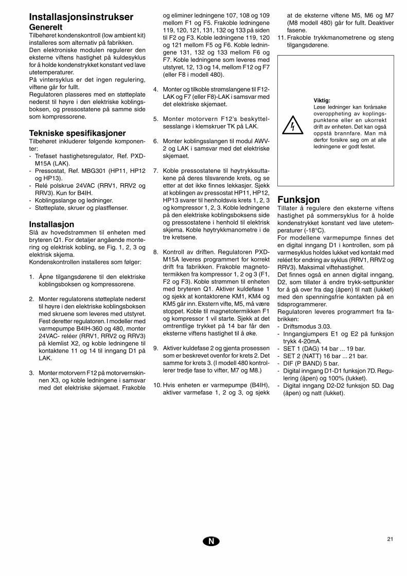
InstallasjonsinstrukserGenereltTilbehøret kondenskontroll (low ambient kit) installeres som alternativ på fabrikken. Den elektroniske modulen regulerer den eksterne viftens hastighet på kuldesyklus for å holde kondenstrykket konstant ved lave utetemperaturer.På vintersyklus er det ingen regulering, viftene går for fullt.Regulatoren plasseres med en støtteplate nederst til høyre i den elektriske koblings-boksen, og pressostatene på samme side som kompressorene.
Tekniske spesifikasjonerTilbehøret inkluderer følgende komponen-ter:- Trefaset hastighetsregulator, Ref. PXD-
M15A (LAK).- Pressostat, Ref. MBG301 (HP11, HP12
og HP13).- Relé polskrue 24VAC (RRV1, RRV2 og
RRV3). Kun for B4IH.- Koblingsslange og ledninger.- Støtteplate, skruer og plastflenser.
InstallasjonSlå av hovedstrømmen til enheten med bryteren Q1. For detaljer angående monte-ring og elektrisk kobling, se Fig. 1, 2, 3 og elektrisk skjema. Kondenskontrollen installeres som følger:
1. Åpne tilgangsdørene til den elektriske koblingsboksen og kompressorene.
2. Monter regulatorens støtteplate nederst til høyre i den elektriske koblingsboksen med skruene som leveres med utstyret. Fest deretter regulatoren. I modeller med varmepumpe B4IH-360 og 480, monter 24VAC- reléer (RRV1, RRV2 og RRV3) på klemlist X2, og koble ledningene til kontaktene 11 og 14 til inngang D1 på LAK.
3. Monter motorvern F12 på motorvernskin-nen X3, og koble ledningene i samsvar med det elektriske skjemaet. Frakoble
og eliminer ledningene 107, 108 og 109 mellom F1 og F5. Frakoble ledningene 119, 120, 121, 131, 132 og 133 på siden til F2 og F3. Koble ledningene 119, 120 og 121 mellom F5 og F6. Koble lednin-gene 131, 132 og 133 mellom F6 og F7. Koble ledningene som leveres med utstyret, 12, 13 og 14, mellom F12 og F7 (eller F8 i modell 480).
4. Monter og tilkoble strømslangene til F12-LAK og F7 (eller F8)-LAK i samsvar med det elektriske skjemaet.
5. Monter motorvern F12’s beskyttel-sesslange i klemskruer TK på LAK.
6. Monter koblingsslangen til modul AWV-2 og LAK i samsvar med det elektriske skjemaet.
7. Koble pressostatene til høytrykksutta-kene på deres tilsvarende krets, og se etter at det ikke finnes lekkasjer. Sjekk at koblingen av pressostat HP11, HP12, HP13 svarer til henholdsvis krets 1, 2, 3 og kompressor 1, 2, 3. Koble ledningene på den elektriske koblingsboksens side og pressostatene i henhold til elektrisk skjema. Koble høytrykkmanometre i de tre kretsene.
8. Kontroll av driften. Regulatoren PXD-M15A leveres programmert for korrekt drift fra fabrikken. Frakoble magneto-termikken fra kompressor 1, 2 og 3 (F1, F2 og F3). Koble strømmen til enheten med bryteren Q1. Aktiver kuldefase 1 og sjekk at kontaktorene KM1, KM4 og KM5 går inn. Ekstern vifte, M5, må være stoppet. Koble til magnetotermikken F1 og kompressor 1 vil starte. Sjekk at det omtrentlige trykket på 14 bar får den eksterne viftens hastighet til å øke.
9. Aktiver kuldefase 2 og gjenta prosessen som er beskrevet ovenfor for krets 2. Det samme for krets 3. (I modell 480 kontrol-lerer tredje fase to vifter, M7 og M8.)
10. Hvis enheten er varmepumpe (B4IH), aktiver varmefase 1, 2 og 3, og sjekk
at de eksterne viftene M5, M6 og M7 (M8 modell 480) går for fullt. Deaktiver fasene.
11. Frakoble trykkmanometrene og steng tilgangsdørene.
Viktig:Løse ledninger kan forårsake overoppheting av koplings-punktene eller en ukorrekt drift av enheten. Det kan også oppstå brannfare. Man må derfor forsikre seg om at alle ledningene er godt festet.
FunksjonTillater å regulere den eksterne viftens hastighet på sommersyklus for å holde kondenstrykket konstant ved lave utetem-peraturer (-18°C). For modellene varmepumpe finnes det en digital inngang D1 i kontrollen, som på varmesyklus holdes lukket ved kontakt med reléet for endring av syklus (RRV1, RRV2 og RRV3). Maksimal viftehastighet.Det finnes også en annen digital inngang, D2, som tillater å endre trykk-settpunkter for å gå over fra dag (åpen) til natt (lukket) med den spenningsfrie kontakten på en tidsprogrammerer.Regulatoren leveres programmert fra fa-brikken:- Driftsmodus 3.03.- Inngangjumpers E1 og E2 på funksjon
trykk 4-20mA. - SET 1 (DAG) 14 bar ... 19 bar.- SET 2 (NATT) 16 bar ... 21 bar.- DIF (P BAND) 5 bar.- Digital inngang D1-D1 funksjon 7D. Regu-
lering (åpen) og 100% (lukket).- Digital inngang D2-D2 funksjon 5D. Dag
(åpen) og natt (lukket).
22 N
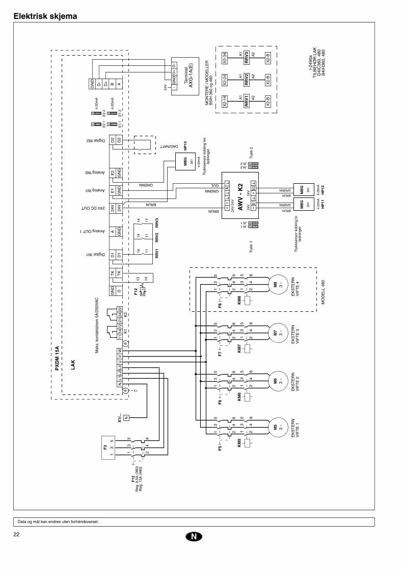
Elektrisk skjema
Data og mål kan endres uten forhåndsvarsel.
����
���
���
�������
��
���
���
����
�����
���
����
��
��
�
��
���
���
�����
�����
�����
�����
����
��
��
�
��
�
��
���
�������
���
����
� �
��
��
��
�
��
��
�
��
�
��
���
�������
���
����
� �
��
��
��
�
��
��
�
��
�
��
���
�������
���
����
� �
��
��
��
�
��
��
�
��
�
��
���
�������
���
����
� �
��
��
��
�
��
��
�
��
�
������
����
����
����
�����
���
�
����������
������
��
���
���
����
����
�
�����������
������������
����������
����������
����������
�����������
����
�����
����
�����
��������
��
�����
�
����
����
������
������
������
����
�
����
�����
����
�����
����
����
������
������
���
����
����
�
���
����
���
�� ��
��
���
�
����
���
��
���
���
��
����
���
��
���
���
��
����
����
����
�
���
���
����
����
��
��
�� ��
����
���
��
��
���
��
��
�
���
���
���
��
���
��
���
��
��
���
������
��������
���
���
����
�
���
�
���
�
���
�
���
�
���
����
��
����
��
�� ��
����
�� ��
����
�� ��
����
���
���
����
��
����
���
����
��
�
����
��
��
��
���
��� �
���
���
���
���
���
���
����
��
����
���
����
���
��������
��������
��
�
���
���
���
���
����
��
����
����
ROMÁN LARRODA
JEFE CONTROL DE CALIDAD
Low ambient Kit para Roof Top D4IC y B4IH-360, 480
Low ambient Kit for Roof Top D4IC and B4IH-360, 480
TIPO:
DIRECTIVAS DE LA CE APLICADAS:
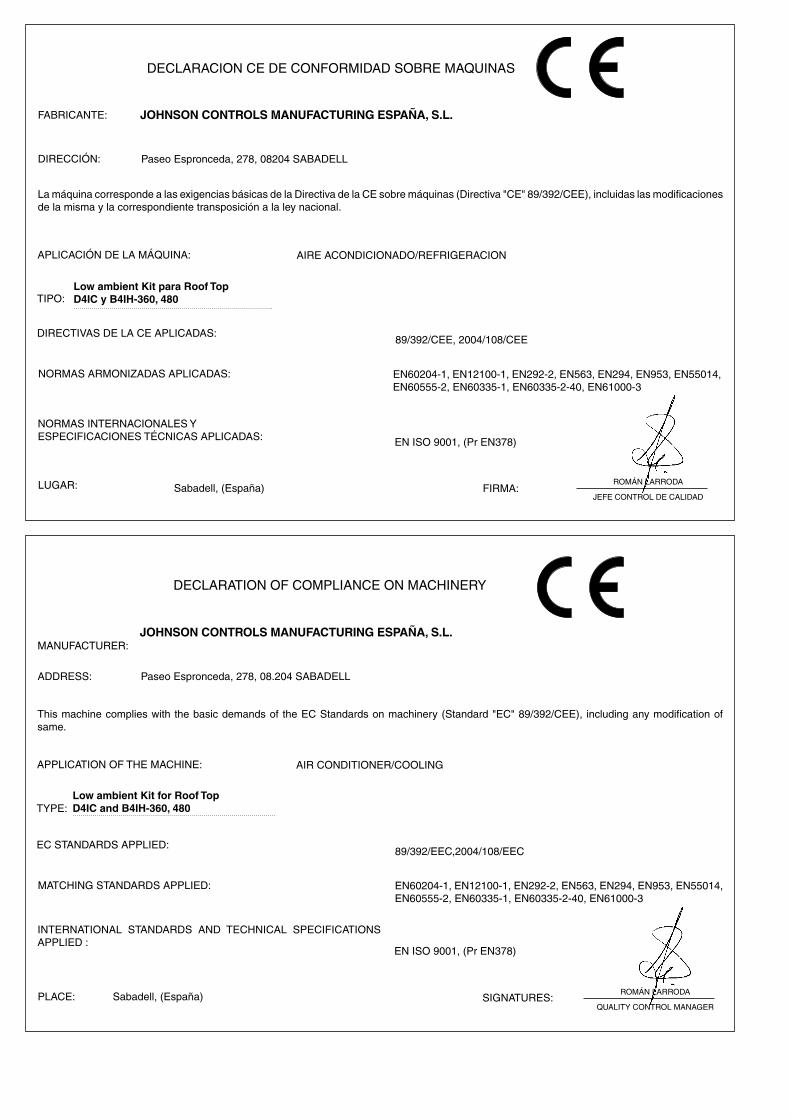
DECLARACION CE DE CONFORMIDAD SOBRE MAQUINAS
FABRICANTE: JOHNSON CONTROLS MANUFACTURING ESPAÑA, S.L.
DIRECCIÓN:
La máquina corresponde a las exigencias básicas de la Directiva de la CE sobre máquinas (Directiva "CE" 89/392/CEE), incluidas las modificaciones de la misma y la correspondiente transposición a la ley nacional.
APLICACIÓN DE LA MÁQUINA: AIRE ACONDICIONADO/REFRIGERACION
NORMAS ARMONIZADAS APLICADAS: EN60204-1, EN12100-1, EN292-2, EN563, EN294, EN953, EN55014, EN60555-2, EN60335-1, EN60335-2-40, EN61000-3
EN ISO 9001, (Pr EN378)
LUGAR: FIRMA:Sabadell, (España)
89/392/CEE, 2004/108/CEE
NORMAS INTERNACIONALES YESPECIFICACIONES TÉCNICAS APLICADAS:
Paseo Espronceda, 278, 08204 SABADELL
TYPE:
EC STANDARDS APPLIED:
DECLARATION OF COMPLIANCE ON MACHINERY
MANUFACTURER:JOHNSON CONTROLS MANUFACTURING ESPAÑA, S.L.
ADDRESS:
This machine complies with the basic demands of the EC Standards on machinery (Standard "EC" 89/392/CEE), including any modification of same.
APPLICATION OF THE MACHINE: AIR CONDITIONER/COOLING
MATCHING STANDARDS APPLIED: EN60204-1, EN12100-1, EN292-2, EN563, EN294, EN953, EN55014, EN60555-2, EN60335-1, EN60335-2-40, EN61000-3
EN ISO 9001, (Pr EN378)
PLACE: SIGNATURES:Sabadell, (España)
89/392/EEC,2004/108/EEC
INTERNATIONAL STANDARDS AND TECHNICAL SPECIFICATIONS APPLIED :
Paseo Espronceda, 278, 08.204 SABADELL
ROMÁN LARRODA
QUALITY CONTROL MANAGER

www.johnsoncontrols.com