Embed Size (px)
Citation preview
T4E - PFA lined Plug Valve
Ahaus GmbHvon-Braun-Straße 19aD-48683 AhausPostfach 1162 D-48661 AhausTelefon: +49(0) 2561-686-100Fax: +49(0) 2561-686-200
Register: 18Page: 1Date: 01.2009Revision: 07.2019
Technical Manual
Register 18 Contents - T4E
ContentsTechnical Data T4E-1, DN½“ to DN6“ ...................................................................2
Technical Data T4E-1, DN8“ to DN14“ ..................................................................3
Technical Data T4E-2, DN15 to DN150 .................................................................4
Technical Data T4E-2, DN200 to DN300 ...............................................................5
Technical Data T4E-3, DN½“ to DN6“ ...................................................................6
Technical Data T4E-3, DN8“, 10“ ..........................................................................7
Material specification T4E-1, DN½“ to DN6“ .........................................................8
Material specification T4E-1, DN8“ to DN14“ ........................................................8
Material specificationT4E-2, DN15 to DN150 ........................................................9
Material specificationT4E-2, DN200 to DN300 ......................................................9
Material specificationT4E-3, DN½“ to DN6“ ........................................................10
Material specification T4E-3, DN8“, 10“...............................................................10
Spare Parts (Item.-No.) T4E ................................................................................11
Assembly instructions T4E ..................................................................................12
Disassembly instructions T4E .............................................................................13
T4E Installation Instructions ................................................................................14
T4E Operating/Maintenance Instructions ............................................................15
T4E-3 - recommended Tightening Torques for Top Cap and Adjuster Boltings*
(300lbs)................................................................................................................16
T4E-1 & T4E-2 - recommended Tightening Torques for Top Cap and Adjuster
Boltings* (150lbs & PN16) ...................................................................................16
T4E-1 & T4E-3 - Dimension sheet for actuator mounting....................................17
T4E-2 - Dimension sheet for actuator mounting ..................................................18
T4E - Actuator Sizing Torques .............................................................................19
T4E - Kv Data and Cv Data (DIN EN 60534-2-3) .................................................20
ET4E - Kv Data and Cv Data (DIN EN 60534-2-3) ...............................................20
Optional plug with side vent hole .........................................................................21
Optional with V-plug or S-plug .............................................................................22
Your distribution partner:
Blindeisenweg 31 • D
-41468 Neuss • Tel.: +49 2131 / 15 39 28-0 • Fax: +49 2131 / 15 39 28-99 • info@
fergo.eu • ww
w.fergo.eu
Your distribution partner:
Blindeisenweg 31 • D
-41468 Neuss • Tel.: +49 2131 / 15 39 28-0 • Fax: +49 2131 / 15 39 28-99 • info@
fergo.eu • ww
w.fergo.eu
T4E - PFA lined Plug Valve
Ahaus GmbHvon-Braun-Straße 19aD-48683 AhausPostfach 1162 D-48661 AhausTelefon: +49(0) 2561-686-100Fax: +49(0) 2561-686-200
Register: 18Page: 2Date: 01.2009Revision: 07.2019
Technical Manual
weight
*
*
* Gear operated
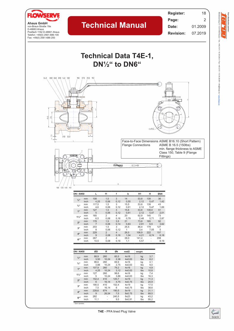
Technical Data T4E-1, DN½“ to DN6“
DN / ANSI L f1 f b H1 H Ød4
½“ mm 108 1,5 3 14 53,8 139 36 inch 4,25 0,06 0,12 0,55 2,12 5,47 1,42
¾“ mm 117,5 1,5 3 15,5 53,8 139 43 inch 4,6 0,06 0,12 0,61 2,12 5,47 1,69
1“ mm 127 1,5 3 15,6 53,8 139,0 51 inch 5 0,06 0,12 0,61 2,12 5,47 2,01
1½“ mm 165 2 4 20 62,9 145 73 inch 6,5 0,08 0,16 0,79 2,48 5,71 2,87
2“ mm 178 1,5 3,5 21 73,8 165 92 inch 7 0,06 0,14 0,83 2,91 6,5 3,62
3“ mm 203 1,5 3 25,5 86,4 179 127 inch 8 0,06 0,12 1 3,4 7,05 5
4“ mm 229 2 4 26,5 106,9 222 157 inch 9 0,08 0,16 1,04 4,21 8,74 6,18
6“ mm 267 2 4 28,0 141,4 - 208 inch 10,5 0,08 0,16 1,1 5,57 - 8,19
DN / ANSI ØD R Øk nxd2
½“ mm 88,9 260 60,5 4x16 kg 3,7 inch 3,50 10,24 2,38 4x0,63 lbs 8,2
¾“ mm 98,6 260 69,9 4x16 kg 4,1 inch 3,88 10,24 2,75 4x0,63 lbs 9,0
1“ mm 107,9 260 79,2 4x16 kg 4,9 inch 4,25 10,24 3,12 4x0,63 lbs 10,8
1½“ mm 127 260 98,6 4x16 kg 7,4 inch 5 10,24 3,88 4x0,63 lbs 16,3
2“ mm 152,4 410 120,7 4x19 kg 11,3 inch 6 16,14 4,75 4x0,75 lbs 24,9
3“ mm 190,5 410 152,4 4x19 kg 17,5 inch 7,5 16,14 6 4x0,75 lbs 38,6
4“ mm 228,6 674 190,5 8x19 kg 31,1 inch 9 26,54 7,5 8x0,75 lbs 68,5
6“ mm 282 - 240,5 8x23 kg 43,2 inch 11,1 - 9,5 8x0,91 lbs 95,2
Face-to-Face Dimensions ASME B16.10 (Short Pattern) Flange Connections ASME B 16.5 (150lbs) min.flangethicknesstoASME Class 150, Table 9 (Flange Fittings)
Your distribution partner:
Blindeisenweg 31 • D
-41468 Neuss • Tel.: +49 2131 / 15 39 28-0 • Fax: +49 2131 / 15 39 28-99 • info@
fergo.eu • ww
w.fergo.eu
T4E - PFA lined Plug Valve
Ahaus GmbHvon-Braun-Straße 19aD-48683 AhausPostfach 1162 D-48661 AhausTelefon: +49(0) 2561-686-100Fax: +49(0) 2561-686-200
Register: 18Page: 3Date: 01.2009Revision: 07.2019
Technical Manual
weight
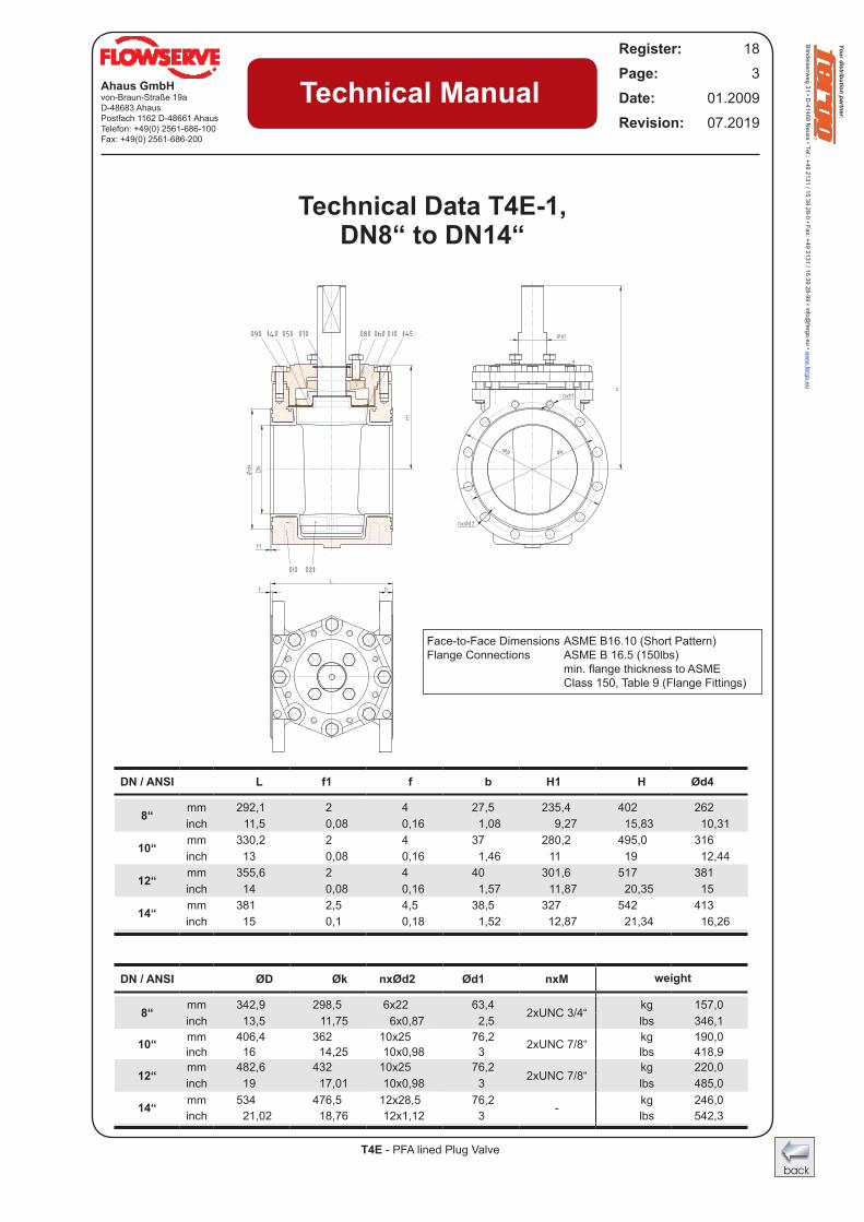
Technical Data T4E-1, DN8“ to DN14“
DN / ANSI L f1 f b H1 H Ød4
8“ mm 292,1 2 4 27,5 235,4 402 262 inch 11,5 0,08 0,16 1,08 9,27 15,83 10,31
10“ mm 330,2 2 4 37 280,2 495,0 316 inch 13 0,08 0,16 1,46 11 19 12,44
12“ mm 355,6 2 4 40 301,6 517 381 inch 14 0,08 0,16 1,57 11,87 20,35 15
14“ mm 381 2,5 4,5 38,5 327 542 413 inch 15 0,1 0,18 1,52 12,87 21,34 16,26
DN / ANSI ØD Øk nxØd2 Ød1 nxM
8“ mm 342,9 298,5 6x22 63,4 2xUNC 3/4“
kg 157,0 inch 13,5 11,75 6x0,87 2,5 lbs 346,1
10“ mm 406,4 362 10x25 76,2 2xUNC 7/8“ kg 190,0 inch 16 14,25 10x0,98 3 lbs 418,9
12“mm 482,6 432 10x25 76,2
2xUNC 7/8“kg 220,0
inch 19 17,01 10x0,98 3 lbs 485,0
14“ mm 534 476,5 12x28,5 76,2 - kg 246,0 inch 21,02 18,76 12x1,12 3 lbs 542,3
Face-to-Face Dimensions ASME B16.10 (Short Pattern) Flange Connections ASME B 16.5 (150lbs) min.flangethicknesstoASME Class 150, Table 9 (Flange Fittings)
Your distribution partner:
Blindeisenweg 31 • D
-41468 Neuss • Tel.: +49 2131 / 15 39 28-0 • Fax: +49 2131 / 15 39 28-99 • info@
fergo.eu • ww
w.fergo.eu
Your distribution partner:
Blindeisenweg 31 • D
-41468 Neuss • Tel.: +49 2131 / 15 39 28-0 • Fax: +49 2131 / 15 39 28-99 • info@
fergo.eu • ww
w.fergo.eu
T4E - PFA lined Plug Valve
Ahaus GmbHvon-Braun-Straße 19aD-48683 AhausPostfach 1162 D-48661 AhausTelefon: +49(0) 2561-686-100Fax: +49(0) 2561-686-200
Register: 18Page: 4Date: 01.2009Revision: 07.2019
Technical Manual
* Face-to-Face Dimensions acc. ASME B 16.10 (Short Pattern) & Gear operated
weight
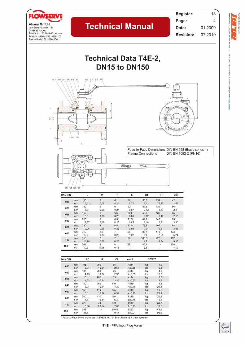
Technical Data T4E-2, DN15 to DN150
DN / DIN L f1 f b H1 H Ød4
015 mm 130 2 6 18 53,8 139 42 inch 5,12 0,08 0,24 0,71 2,12 5,47 1,65
020 mm 150 2 6 22 53,8 139 56 inch 5,91 0,08 0,24 0,87 2,12 5,47 2,2
025 mm 160 2 6,5 20,5 53,8 139 65 inch 6,3 0,08 0,26 0,81 2,12 5,47 2,56
040 mm 200 2 6,5 21,5 62,9 145 85 inch 7,87 0,08 0,26 0,85 2,48 5,71 3,35
050 mm 230 2 6,5 23,5 73,8 165 98 inch 9,06 0,08 0,26 0,93 2,91 6,5 3,86
080 mm 310 2,0 7 26 86,4 179 133 inch 12,2 0,08 0,28 1,02 3,4 7,05 5,24
100 mm 350 2 7 28 106,9 222 152 inch 13,78 0,08 0,28 1,1 4,21 8,74 5,98
150 * mm 267 2 4 28 141,4 - 208 inch 10,51 0,08 0,16 1,1 5,57 - 8,19
DN / DIN ØD R Øk nxd2
015 mm 95 260 65 4x14 kg 4,2 inch 3,74 10,24 2,56 4x0,55 lbs 9,3
020 mm 105 260 75 4x14 kg 4,9 inch 4,13 10,24 2,95 4x0,55 lbs 10,8
025 mm 115 260 85 4x14 kg 5,8 inch 4,53 10,24 3,35 4x0,55 lbs 12,8
040 mm 150 260 110 4x19 kg 9,1 inch 5,91 10,24 4,33 4x0,75 lbs 20,1
050 mm 165 410 125 4x19 kg 13,2 inch 6,5 16,14 4,92 4x0,75 lbs 29,1
080 mm 200 410 160 8x19 kg 20,8 inch 7,87 16,14 6,3 8x0,75 lbs 45,8
100 mm 220 674 180 8x19 kg 34,7 inch 8,66 26,54 7,09 8x0,75 lbs 76,5
150 * mm 282 - 240,5 8x23 kg 43,2 inch 11,1 - 9,47 8x0,91 lbs 95,2
Face-to-Face Dimensions DIN EN 558 (Basic series 1) Flange Connections DIN EN 1092-2 (PN16)
Your distribution partner:
Blindeisenweg 31 • D
-41468 Neuss • Tel.: +49 2131 / 15 39 28-0 • Fax: +49 2131 / 15 39 28-99 • info@
fergo.eu • ww
w.fergo.eu
T4E - PFA lined Plug Valve
Ahaus GmbHvon-Braun-Straße 19aD-48683 AhausPostfach 1162 D-48661 AhausTelefon: +49(0) 2561-686-100Fax: +49(0) 2561-686-200
Register: 18Page: 5Date: 01.2009Revision: 07.2019
Technical Manual
weight
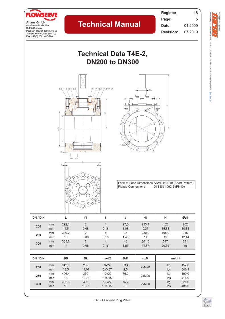
Technical Data T4E-2, DN200 to DN300
DN / DIN L f1 f b H1 H Ød4
200 mm 292,1 2 4 27,5 235,4 402 262 inch 11,5 0,08 0,16 1,08 9,27 15,83 10,31
250 mm 330,2 2 4 37 280,2 495,0 316 inch 13 0,08 0,16 1,46 11 19 12,44
300 mm 355,6 2 4 40 301,6 517 381 inch 14 0,08 0,16 1,57 11,87 20,35 15
DN / DIN ØD Øk nxd2 Ød1 nxM
200 mm 342,9 295 6x22 63,4 2xM20
kg 157,0 inch 13,5 11,61 6x0,87 2,5 lbs 346,1
250 mm 406,4 350 10x22 76,2 2xM20
kg 190,0 inch 16 13,78 10x0,87 3 lbs 418,9
300 mm 482,6 400 10x22 76,2 2xM20 kg 220,0 inch 19 15,75 10x0,87 3 lbs 485,0
Face-to-Face Dimensions ASME B16.10 (Short Pattern) Flange Connections DIN EN 1092-2 (PN10)
Your distribution partner:
Blindeisenweg 31 • D
-41468 Neuss • Tel.: +49 2131 / 15 39 28-0 • Fax: +49 2131 / 15 39 28-99 • info@
fergo.eu • ww
w.fergo.eu
Your distribution partner:
Blindeisenweg 31 • D
-41468 Neuss • Tel.: +49 2131 / 15 39 28-0 • Fax: +49 2131 / 15 39 28-99 • info@
fergo.eu • ww
w.fergo.eu
T4E - PFA lined Plug Valve
Ahaus GmbHvon-Braun-Straße 19aD-48683 AhausPostfach 1162 D-48661 AhausTelefon: +49(0) 2561-686-100Fax: +49(0) 2561-686-200
Register: 18Page: 6Date: 01.2009Revision: 07.2019
Technical Manual
weight
*
*
* Gear operated
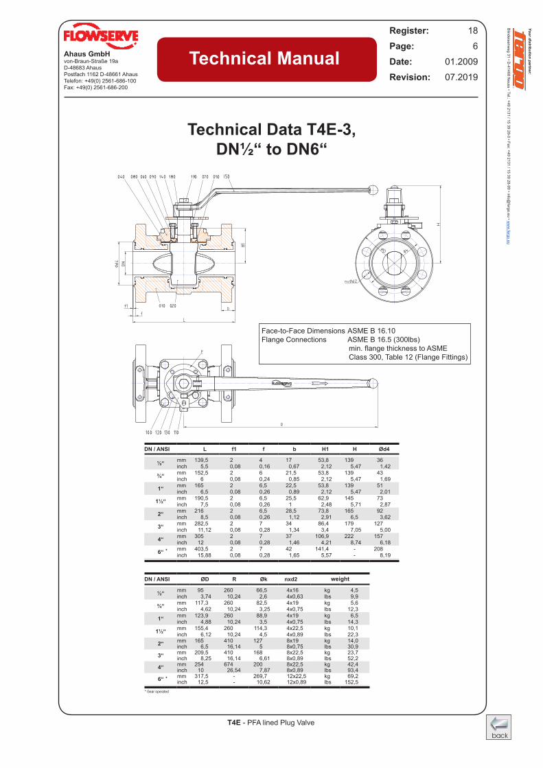
Technical Data T4E-3, DN½“ to DN6“
DN / ANSI L f1 f b H1 H Ød4
½“ mm 139,5 2 4 17 53,8 139 36 inch 5,5 0,08 0,16 0,67 2,12 5,47 1,42
¾“ mm 152,5 2 6 21,5 53,8 139 43 inch 6 0,08 0,24 0,85 2,12 5,47 1,69
1“ mm 165 2 6,5 22,5 53,8 139 51 inch 6,5 0,08 0,26 0,89 2,12 5,47 2,01
1½“ mm 190,5 2 6,5 25,5 62,9 145 73 inch 7,5 0,08 0,26 1 2,48 5,71 2,87
2“ mm 216 2 6,5 28,5 73,8 165 92 inch 8,5 0,08 0,26 1,12 2,91 6,5 3,62
3“ mm 282,5 2 7 34 86,4 179 127 inch 11,12 0,08 0,28 1,34 3,4 7,05 5,00
4“ mm 305 2 7 37 106,9 222 157 inch 12 0,08 0,28 1,46 4,21 8,74 6,18
6“ mm 403,5 2 7 42 141,4 - 208 inch 15,88 0,08 0,28 1,65 5,57 - 8,19
DN / ANSI ØD R Øk nxd2
½“ mm 95 260 66,5 4x16 kg 4,5 inch 3,74 10,24 2,6 4x0,63 lbs 9,9
¾“ mm 117,3 260 82,5 4x19 kg 5,6 inch 4,62 10,24 3,25 4x0,75 lbs 12,3
1“ mm 123,9 260 88,9 4x19 kg 6,5 inch 4,88 10,24 3,5 4x0,75 lbs 14,3
1½“ mm 155,4 260 114,3 4x22,5 kg 10,1 inch 6,12 10,24 4,5 4x0,89 lbs 22,3
2“ mm 165 410 127 8x19 kg 14,0 inch 6,5 16,14 5 8x0,75 lbs 30,9
3“ mm 209,5 410 168 8x22,5 kg 23,7 inch 8,25 16,14 6,61 8x0,89 lbs 52,2
4“ mm 254 674 200 8x22,5 kg 42,4 inch 10 26,54 7,87 8x0,89 lbs 93,4
6“ mm 317,5 - 269,7 12x22,5 kg 69,2 inch 12,5 - 10,62 12x0,89 lbs 152,5
Face-to-Face Dimensions ASME B 16.10 Flange Connections ASME B 16.5 (300lbs) min.flangethicknesstoASME Class 300, Table 12 (Flange Fittings)
Your distribution partner:
Blindeisenweg 31 • D
-41468 Neuss • Tel.: +49 2131 / 15 39 28-0 • Fax: +49 2131 / 15 39 28-99 • info@
fergo.eu • ww
w.fergo.eu
T4E - PFA lined Plug Valve
Ahaus GmbHvon-Braun-Straße 19aD-48683 AhausPostfach 1162 D-48661 AhausTelefon: +49(0) 2561-686-100Fax: +49(0) 2561-686-200
Register: 18Page: 7Date: 01.2009Revision: 07.2019
Technical Manual
weight
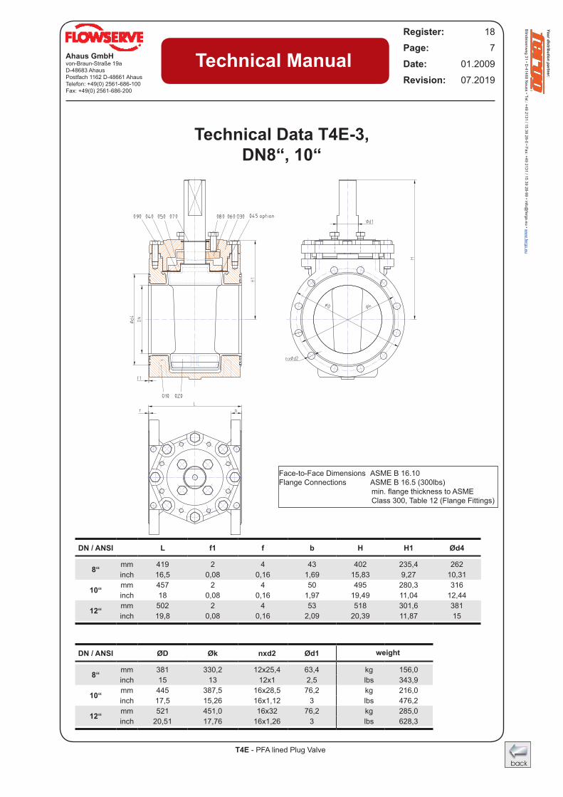
Technical Data T4E-3, DN8“, 10“
DN / ANSI L f1 f b H H1 Ød4
8“ mm 419 2 4 43 402 235,4 262 inch 16,5 0,08 0,16 1,69 15,83 9,27 10,31
10“ mm 457 2 4 50 495 280,3 316 inch 18 0,08 0,16 1,97 19,49 11,04 12,44
12“ mm 502 2 4 53 518 301,6 381 inch 19,8 0,08 0,16 2,09 20,39 11,87 15
DN / ANSI ØD Øk nxd2 Ød1
8“ mm 381 330,2 12x25,4 63,4 kg 156,0 inch 15 13 12x1 2,5 lbs 343,9
10“ mm 445 387,5 16x28,5 76,2 kg 216,0 inch 17,5 15,26 16x1,12 3 lbs 476,2
12“ mm 521 451,0 16x32 76,2 kg 285,0 inch 20,51 17,76 16x1,26 3 lbs 628,3
Face-to-Face Dimensions ASME B 16.10Flange Connections ASME B 16.5 (300lbs) min.flangethicknesstoASME Class 300, Table 12 (Flange Fittings)
Your distribution partner:
Blindeisenweg 31 • D
-41468 Neuss • Tel.: +49 2131 / 15 39 28-0 • Fax: +49 2131 / 15 39 28-99 • info@
fergo.eu • ww
w.fergo.eu
Your distribution partner:
Blindeisenweg 31 • D
-41468 Neuss • Tel.: +49 2131 / 15 39 28-0 • Fax: +49 2131 / 15 39 28-99 • info@
fergo.eu • ww
w.fergo.eu
T4E - PFA lined Plug Valve
Ahaus GmbHvon-Braun-Straße 19aD-48683 AhausPostfach 1162 D-48661 AhausTelefon: +49(0) 2561-686-100Fax: +49(0) 2561-686-200
Register: 18Page: 8Date: 01.2009Revision: 07.2019
Technical Manual
Stainless Steel
Ductile Cast Iron
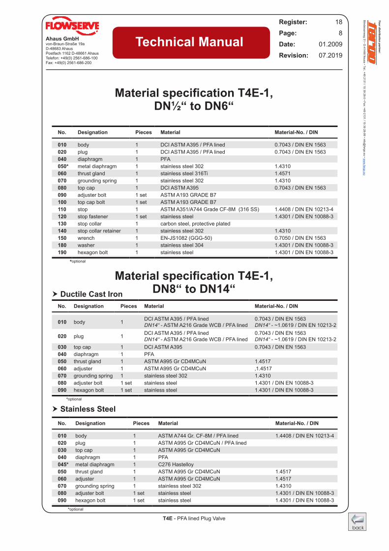
Material specification T4E-1, DN½“ to DN6“
Material specification T4E-1, DN8“ to DN14“
No. Designation Pieces Material Material-No. / DIN
010 body 1 DCI ASTM A395 / PFA lined 0.7043 / DIN EN 1563020 plug 1 DCI ASTM A395 / PFA lined 0.7043 / DIN EN 1563040 diaphragm 1 PFA050* metal diaphragm 1 stainless steel 302 1.4310060 thrust gland 1 stainless steel 316Ti 1.4571070 grounding spring 1 stainless steel 302 1.4310080 top cap 1 DCI ASTM A395 0.7043 / DIN EN 1563090 adjuster bolt 1 set ASTM A193 GRADE B7100 top cap bolt 1 set ASTM A193 GRADE B7110 stop 1 ASTM A351/A744 Grade CF-8M (316 SS) 1.4408 / DIN EN 10213-4120 stop fastener 1 set stainless steel 1.4301 / DIN EN 10088-3130 stop collar 1 carbon steel, protective plated140 stop collar retainer 1 stainless steel 302 1.4310150 wrench 1 EN-JS1082 (GGG-50) 0.7050 / DIN EN 1563180 washer 1 stainless steel 304 1.4301 / DIN EN 10088-3190 hexagon bolt 1 stainless steel 1.4301 / DIN EN 10088-3
*optional
No. Designation Pieces Material Material-No. / DIN
010 body 1 DCI ASTM A395 / PFA lined DN14“ - ASTM A216 Grade WCB / PFA lined
0.7043 / DIN EN 1563 DN14“ - ~1.0619 / DIN EN 10213-2
020 plug 1 DCI ASTM A395 / PFA lined DN14“ - ASTM A216 Grade WCB / PFA lined
0.7043 / DIN EN 1563 DN14“ - ~1.0619 / DIN EN 10213-2
030 top cap 1 DCI ASTM A395 0.7043 / DIN EN 1563040 diaphragm 1 PFA050 thrust gland 1 ASTM A995 Gr CD4MCuN 1.4517060 adjuster 1 ASTM A995 Gr CD4MCuN ‚1.4517070 grounding spring 1 stainless steel 302 1.4310080 adjuster bolt 1 set stainless steel 1.4301 / DIN EN 10088-3090 hexagon bolt 1 set stainless steel 1.4301 / DIN EN 10088-3
*optional
No. Designation Pieces Material Material-No. / DIN
010 body 1 ASTM A744 Gr. CF-8M / PFA lined 1.4408 / DIN EN 10213-4020 plug 1 ASTM A995 Gr CD4MCuN / PFA lined030 top cap 1 ASTM A995 Gr CD4MCuN040 diaphragm 1 PFA045* metal diaphragm 1 C276 Hastelloy050 thrust gland 1 ASTM A995 Gr CD4MCuN 1.4517060 adjuster 1 ASTM A995 Gr CD4MCuN 1.4517070 grounding spring 1 stainless steel 302 1.4310080 adjuster bolt 1 set stainless steel 1.4301 / DIN EN 10088-3090 hexagon bolt 1 set stainless steel 1.4301 / DIN EN 10088-3
*optional
Your distribution partner:
Blindeisenweg 31 • D
-41468 Neuss • Tel.: +49 2131 / 15 39 28-0 • Fax: +49 2131 / 15 39 28-99 • info@
fergo.eu • ww
w.fergo.eu
T4E - PFA lined Plug Valve
Ahaus GmbHvon-Braun-Straße 19aD-48683 AhausPostfach 1162 D-48661 AhausTelefon: +49(0) 2561-686-100Fax: +49(0) 2561-686-200
Register: 18Page: 9Date: 01.2009Revision: 07.2019
Technical Manual
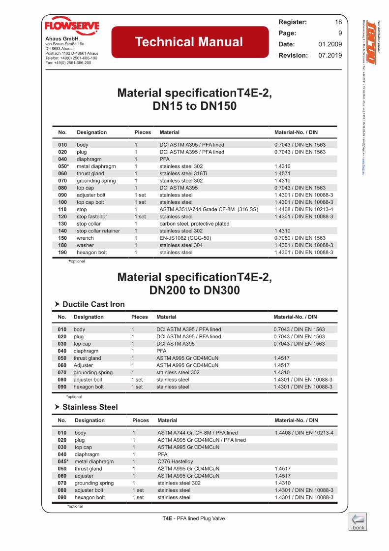
Material specificationT4E-2, DN15 to DN150
Material specificationT4E-2, DN200 to DN300
No. Designation Pieces Material Material-No. / DIN
010 body 1 DCI ASTM A395 / PFA lined DN14“ - ASTM A216 Grade WCB / PFA lined
0.7043 / DIN EN 1563 DN14“ - ~1.0619 / DIN EN 10213-2
020 plug 1 DCI ASTM A395 / PFA lined DN14“ - ASTM A216 Grade WCB / PFA lined
0.7043 / DIN EN 1563 DN14“ - ~1.0619 / DIN EN 10213-2
030 top cap 1 DCI ASTM A395 0.7043 / DIN EN 1563040 diaphragm 1 PFA050 thrust gland 1 ASTM A995 Gr CD4MCuN 1.4517060 adjuster 1 ASTM A995 Gr CD4MCuN ‚1.4517070 grounding spring 1 stainless steel 302 1.4310080 adjuster bolt 1 set stainless steel 1.4301 / DIN EN 10088-3090 hexagon bolt 1 set stainless steel 1.4301 / DIN EN 10088-3
*optional
No. Designation Pieces Material Material-No. / DIN
010 body 1 DCI ASTM A395 / PFA lined 0.7043 / DIN EN 1563020 plug 1 DCI ASTM A395 / PFA lined 0.7043 / DIN EN 1563040 diaphragm 1 PFA050* metal diaphragm 1 stainless steel 302 1.4310060 thrust gland 1 stainless steel 316Ti 1.4571070 grounding spring 1 stainless steel 302 1.4310080 top cap 1 DCI ASTM A395 0.7043 / DIN EN 1563090 adjuster bolt 1 set stainless steel 1.4301 / DIN EN 10088-3100 top cap bolt 1 set stainless steel 1.4301 / DIN EN 10088-3110 stop 1 ASTM A351/A744 Grade CF-8M (316 SS) 1.4408 / DIN EN 10213-4120 stop fastener 1 set stainless steel 1.4301 / DIN EN 10088-3130 stop collar 1 carbon steel, protective plated140 stop collar retainer 1 stainless steel 302 1.4310150 wrench 1 EN-JS1082 (GGG-50) 0.7050 / DIN EN 1563180 washer 1 stainless steel 304 1.4301 / DIN EN 10088-3190 hexagon bolt 1 stainless steel 1.4301 / DIN EN 10088-3
*optional
No. Designation Pieces Material Material-No. / DIN
010 body 1 DCI ASTM A395 / PFA lined 0.7043 / DIN EN 1563020 plug 1 DCI ASTM A395 / PFA lined 0.7043 / DIN EN 1563030 top cap 1 DCI ASTM A395 0.7043 / DIN EN 1563040 diaphragm 1 PFA050 thrust gland 1 ASTM A995 Gr CD4MCuN 1.4517060 Adjuster 1 ASTM A995 Gr CD4MCuN 1.4517070 grounding spring 1 stainless steel 302 1.4310080 adjuster bolt 1 set stainless steel 1.4301 / DIN EN 10088-3090 hexagon bolt 1 set stainless steel 1.4301 / DIN EN 10088-3
*optional
No. Designation Pieces Material Material-No. / DIN
010 body 1 ASTM A744 Gr. CF-8M / PFA lined 1.4408 / DIN EN 10213-4020 plug 1 ASTM A995 Gr CD4MCuN / PFA lined030 top cap 1 ASTM A995 Gr CD4MCuN040 diaphragm 1 PFA045* metal diaphragm 1 C276 Hastelloy050 thrust gland 1 ASTM A995 Gr CD4MCuN 1.4517060 adjuster 1 ASTM A995 Gr CD4MCuN 1.4517070 grounding spring 1 stainless steel 302 1.4310080 adjuster bolt 1 set stainless steel 1.4301 / DIN EN 10088-3090 hexagon bolt 1 set stainless steel 1.4301 / DIN EN 10088-3
*optional
Stainless Steel
Ductile Cast Iron
Your distribution partner:
Blindeisenweg 31 • D
-41468 Neuss • Tel.: +49 2131 / 15 39 28-0 • Fax: +49 2131 / 15 39 28-99 • info@
fergo.eu • ww
w.fergo.eu
Your distribution partner:
Blindeisenweg 31 • D
-41468 Neuss • Tel.: +49 2131 / 15 39 28-0 • Fax: +49 2131 / 15 39 28-99 • info@
fergo.eu • ww
w.fergo.eu
T4E - PFA lined Plug Valve
Ahaus GmbHvon-Braun-Straße 19aD-48683 AhausPostfach 1162 D-48661 AhausTelefon: +49(0) 2561-686-100Fax: +49(0) 2561-686-200
Register: 18Page: 10Date: 01.2009Revision: 07.2019
Technical Manual
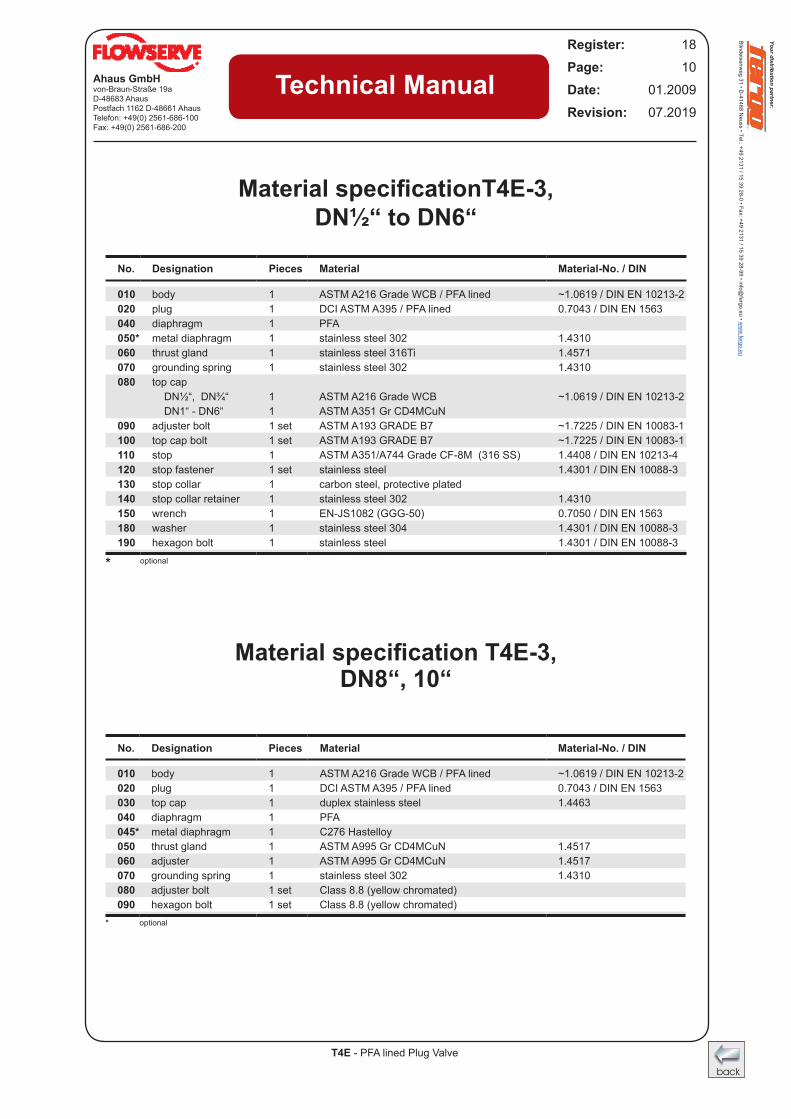
Material specificationT4E-3, DN½“ to DN6“
Material specification T4E-3, DN8“, 10“
No. Designation Pieces Material Material-No. / DIN
010 body 1 ASTM A216 Grade WCB / PFA lined ~1.0619 / DIN EN 10213-2020 plug 1 DCI ASTM A395 / PFA lined 0.7043 / DIN EN 1563040 diaphragm 1 PFA050* metal diaphragm 1 stainless steel 302 1.4310060 thrust gland 1 stainless steel 316Ti 1.4571070 grounding spring 1 stainless steel 302 1.4310080 top cap
DN½“, DN¾“ 1 ASTM A216 Grade WCB ~1.0619 / DIN EN 10213-2DN1“ - DN6“ 1 ASTM A351 Gr CD4MCuN
090 adjuster bolt 1 set ASTM A193 GRADE B7 ~1.7225 / DIN EN 10083-1100 top cap bolt 1 set ASTM A193 GRADE B7 ~1.7225 / DIN EN 10083-1110 stop 1 ASTM A351/A744 Grade CF-8M (316 SS) 1.4408 / DIN EN 10213-4120 stop fastener 1 set stainless steel 1.4301 / DIN EN 10088-3130 stop collar 1 carbon steel, protective plated140 stop collar retainer 1 stainless steel 302 1.4310150 wrench 1 EN-JS1082 (GGG-50) 0.7050 / DIN EN 1563180 washer 1 stainless steel 304 1.4301 / DIN EN 10088-3190 hexagon bolt 1 stainless steel 1.4301 / DIN EN 10088-3
* optional
No. Designation Pieces Material Material-No. / DIN
010 body 1 ASTM A216 Grade WCB / PFA lined ~1.0619 / DIN EN 10213-2020 plug 1 DCI ASTM A395 / PFA lined 0.7043 / DIN EN 1563030 top cap 1 duplex stainless steel 1.4463040 diaphragm 1 PFA045* metal diaphragm 1 C276 Hastelloy050 thrust gland 1 ASTM A995 Gr CD4MCuN 1.4517060 adjuster 1 ASTM A995 Gr CD4MCuN 1.4517070 grounding spring 1 stainless steel 302 1.4310080 adjuster bolt 1 set Class 8.8 (yellow chromated)090 hexagon bolt 1 set Class 8.8 (yellow chromated)
* optional
Your distribution partner:
Blindeisenweg 31 • D
-41468 Neuss • Tel.: +49 2131 / 15 39 28-0 • Fax: +49 2131 / 15 39 28-99 • info@
fergo.eu • ww
w.fergo.eu
T4E - PFA lined Plug Valve
Ahaus GmbHvon-Braun-Straße 19aD-48683 AhausPostfach 1162 D-48661 AhausTelefon: +49(0) 2561-686-100Fax: +49(0) 2561-686-200
Register: 18Page: 11Date: 01.2009Revision: 07.2019
Technical Manual
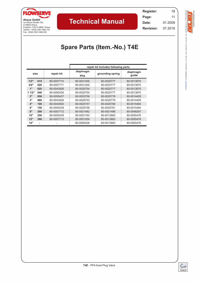
Spare Parts (Item.-No.) T4E
PFA
1/2" 015 80-0057710 80-0031400 80-0025777 80-00138703/4" 020 80-0057711 80-0031400 80-0025777 80-00138701" 025 80-0043928 80-0025754 80-0025777 80-0013870
1 1/2" 040 80-0055436 80-0025755 80-0025777 80-00138702" 050 80-0055437 80-0025756 80-0025778 80-00144053" 080 80-0043929 80-0025703 80-0025779 80-00144054" 100 80-0043930 80-0025757 80-0025780 80-00154846" 150 80-0055438 80-0025758 80-0025781 80-00154848" 200 80-0057712 80-0021482 80-0021486 80-004828710" 250 80-0055439 80-0051193 80-0013883 80-005547612" 300 80-0057713 80-0051004 80-0013883 80-005547614" - - 80-0065028 80-0013883 80-0055476
repair kit includes following parts
size repair kitdiaphragm
grounding spring diaphragmguide
Your distribution partner:
Blindeisenweg 31 • D
-41468 Neuss • Tel.: +49 2131 / 15 39 28-0 • Fax: +49 2131 / 15 39 28-99 • info@
fergo.eu • ww
w.fergo.eu
Your distribution partner:
Blindeisenweg 31 • D
-41468 Neuss • Tel.: +49 2131 / 15 39 28-0 • Fax: +49 2131 / 15 39 28-99 • info@
fergo.eu • ww
w.fergo.eu
T4E - PFA lined Plug Valve
Ahaus GmbHvon-Braun-Straße 19aD-48683 AhausPostfach 1162 D-48661 AhausTelefon: +49(0) 2561-686-100Fax: +49(0) 2561-686-200
Register: 18Page: 12Date: 01.2009Revision: 07.2019
Technical Manual
010
020
040
050*
060
070
110
120
080
100
090
130
140
150
180
190
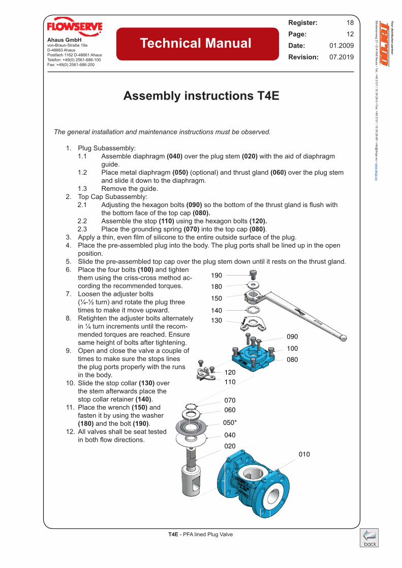
The general installation and maintenance instructions must be observed.
1. Plug Subassembly:1.1 Assemble diaphragm (040) over the plug stem (020) with the aid of diaphragm
guide.1.2 Place metal diaphragm (050) (optional) and thrust gland (060) over the plug stem
and slide it down to the diaphragm.1.3 Remove the guide.
2. Top Cap Subassembly:2.1 Adjusting the hexagon bolts (090)sothebottomofthethrustglandisflushwith
the bottom face of the top cap (080).2.2 Assemble the stop (110) using the hexagon bolts (120).2.3 Place the grounding spring (070) into the top cap (080).
3. Applyathin,evenfilmofsiliconetotheentireoutsidesurfaceoftheplug.4. Place the pre-assembled plug into the body. The plug ports shall be lined up in the open
position.5. Slide the pre-assembled top cap over the plug stem down until it rests on the thrust gland.6. Place the four bolts (100) and tighten
them using the criss-cross method ac-cording the recommended torques.
7. Loosen the adjuster bolts (¼-½ turn) and rotate the plug three
times to make it move upward.8. Retighten the adjuster bolts alternately
in ¼ turn increments until the recom-mended torques are reached. Ensure same height of bolts after tightening.
9. Open and close the valve a couple of times to make sure the stops lines the plug ports properly with the runs in the body.
10. Slide the stop collar (130) over the stem afterwards place the stop collar retainer (140).
11. Place the wrench (150) and fasten it by using the washer (180) and the bolt (190).
12. All valves shall be seat tested inbothflowdirections.
Assembly instructions T4E
Your distribution partner:
Blindeisenweg 31 • D
-41468 Neuss • Tel.: +49 2131 / 15 39 28-0 • Fax: +49 2131 / 15 39 28-99 • info@
fergo.eu • ww
w.fergo.eu
T4E - PFA lined Plug Valve
Ahaus GmbHvon-Braun-Straße 19aD-48683 AhausPostfach 1162 D-48661 AhausTelefon: +49(0) 2561-686-100Fax: +49(0) 2561-686-200
Register: 18Page: 13Date: 01.2009Revision: 07.2019
Technical Manual
010
020
040
050*
060
070
110
120
080
100
090
130
140
150
180
190
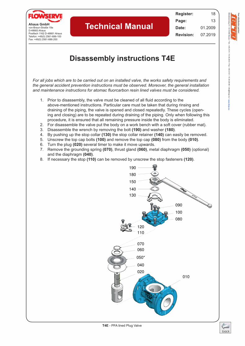
For all jobs which are to be carried out on an installed valve, the works safety requirements and the general accident prevention instructions must be observed. Moreover, the general installation and maintenance instructions for atomac fluorcarbon resin lined valves must be considered.
1. Priortodisassembly,thevalvemustbecleanedofallfluidaccordingtothe above-mentioned instructions. Particular care must be taken that during rinsing and
draining of the piping, the valve is opened and closed repeatedly. These cycles (open-ing and closing) are to be repeated during draining of the piping. Only when following this procedure, it is ensured that all remaining pressure inside the body is eliminated.
2. For disassemble the valve put the body on a work bench with a soft cover (rubber mat). 3. Disassemble the wrench by removing the bolt (190) and washer (180). 4. By pushing up the stop collar (130) the stop collar retainer (140) can easily be removed.5. Unscrew the top cap bolts (100) and remove the top cap (080) from the body (010).6. Turn the plug (020) several timer to make it move upwards.7. Remove the grounding spring (070), thrust gland (060), metal diaphragm (050) (optional)
and the diaphragm (040).8. If necessary the stop (110) can be removed by unscrew the stop fasteners (120).
Disassembly instructions T4E
Your distribution partner:
Blindeisenweg 31 • D
-41468 Neuss • Tel.: +49 2131 / 15 39 28-0 • Fax: +49 2131 / 15 39 28-99 • info@
fergo.eu • ww
w.fergo.eu
Your distribution partner:
Blindeisenweg 31 • D
-41468 Neuss • Tel.: +49 2131 / 15 39 28-0 • Fax: +49 2131 / 15 39 28-99 • info@
fergo.eu • ww
w.fergo.eu
T4E - PFA lined Plug Valve
Ahaus GmbHvon-Braun-Straße 19aD-48683 AhausPostfach 1162 D-48661 AhausTelefon: +49(0) 2561-686-100Fax: +49(0) 2561-686-200
Register: 18Page: 14Date: 01.2009Revision: 07.2019
Technical Manual
010
020
040
050*
060
070
110
120
080
100
090
130
140
150
180
190
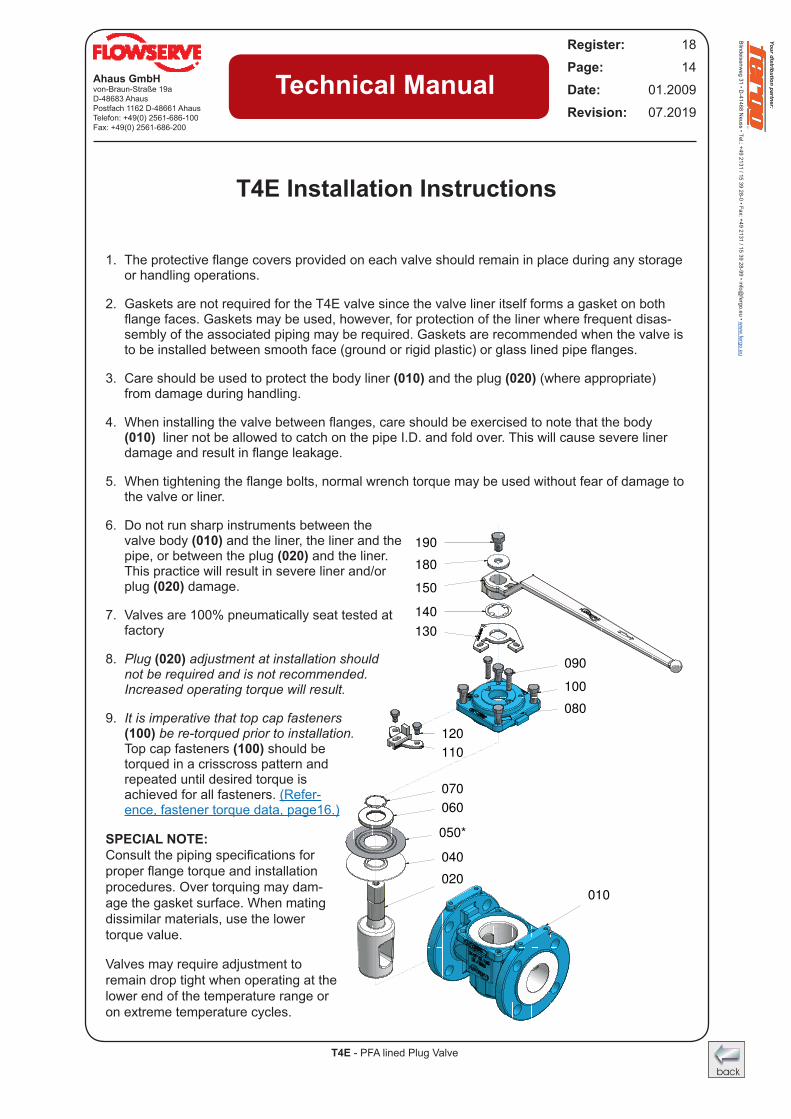
1. Theprotectiveflangecoversprovidedoneachvalveshouldremaininplaceduringanystorageor handling operations.
2. Gaskets are not required for the T4E valve since the valve liner itself forms a gasket on both flangefaces.Gasketsmaybeused,however,forprotectionofthelinerwherefrequentdisas-sembly of the associated piping may be required. Gaskets are recommended when the valve is tobeinstalledbetweensmoothface(groundorrigidplastic)orglasslinedpipeflanges.
3. Care should be used to protect the body liner (010) and the plug (020) (where appropriate) from damage during handling.
4. Wheninstallingthevalvebetweenflanges,careshouldbeexercisedtonotethatthebody(010) liner not be allowed to catch on the pipe I.D. and fold over. This will cause severe liner damageandresultinflangeleakage.
5. Whentighteningtheflangebolts,normalwrenchtorquemaybeusedwithoutfearofdamagetothe valve or liner.
6. Do not run sharp instruments between the valve body (010) and the liner, the liner and the pipe, or between the plug (020) and the liner. This practice will result in severe liner and/or plug (020) damage.
7. Valves are 100% pneumatically seat tested at factory
8. Plug (020) adjustment at installation should not be required and is not recommended. Increased operating torque will result.
9. It is imperative that top cap fasteners (100) be re-torqued prior to installation. Top cap fasteners (100) should be torqued in a crisscross pattern and repeated until desired torque is achieved for all fasteners. (Refer-ence, fastener torque data, page16.)
SPECIAL NOTE: Consultthepipingspecificationsforproperflangetorqueandinstallationprocedures. Over torquing may dam-age the gasket surface. When mating dissimilar materials, use the lower torque value.
Valves may require adjustment to remain drop tight when operating at the lower end of the temperature range or on extreme temperature cycles.
T4E Installation Instructions
Your distribution partner:
Blindeisenweg 31 • D
-41468 Neuss • Tel.: +49 2131 / 15 39 28-0 • Fax: +49 2131 / 15 39 28-99 • info@
fergo.eu • ww
w.fergo.eu
T4E - PFA lined Plug Valve
Ahaus GmbHvon-Braun-Straße 19aD-48683 AhausPostfach 1162 D-48661 AhausTelefon: +49(0) 2561-686-100Fax: +49(0) 2561-686-200
Register: 18Page: 15Date: 01.2009Revision: 07.2019
Technical Manual
010
020
040
050*
060
070
110
120
080
100
090
130
140
150
180
190
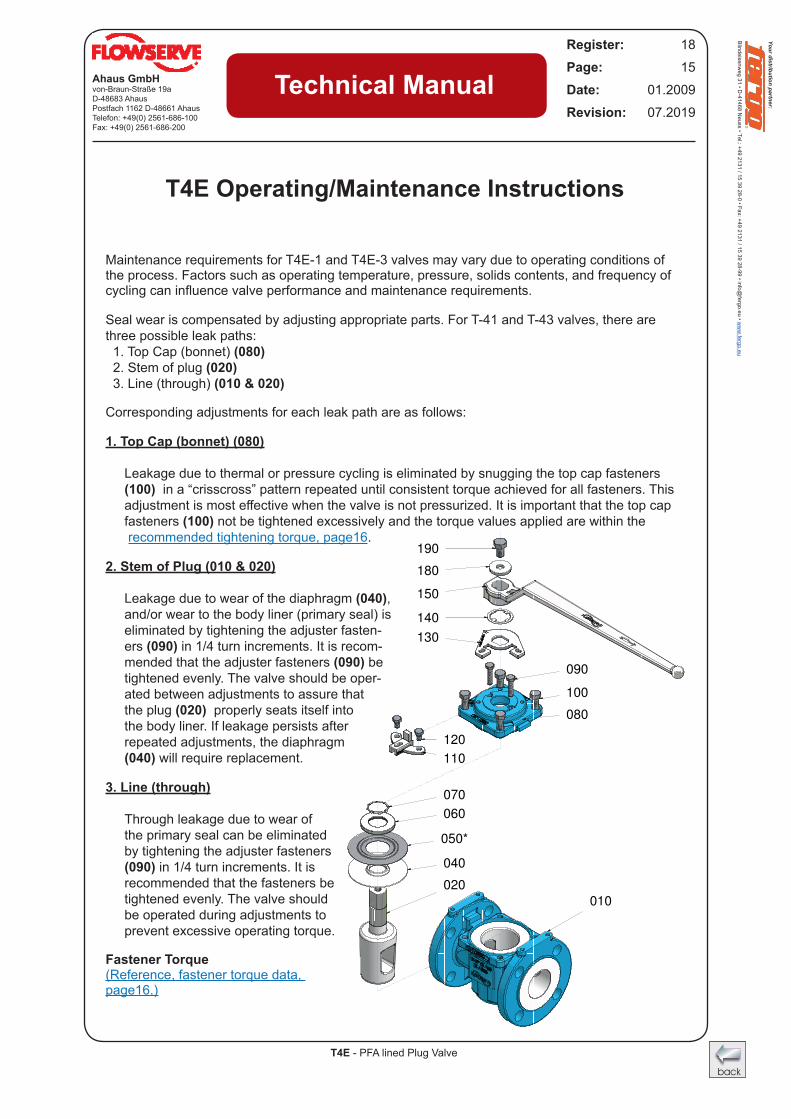
Maintenance requirements for T4E-1 and T4E-3 valves may vary due to operating conditions of the process. Factors such as operating temperature, pressure, solids contents, and frequency of cyclingcaninfluencevalveperformanceandmaintenancerequirements.
Seal wear is compensated by adjusting appropriate parts. For T-41 and T-43 valves, there are three possible leak paths: 1. Top Cap (bonnet) (080) 2. Stem of plug (020) 3. Line (through) (010 & 020)
Corresponding adjustments for each leak path are as follows:
1. Top Cap (bonnet) (080) Leakage due to thermal or pressure cycling is eliminated by snugging the top cap fasteners (100) in a “crisscross” pattern repeated until consistent torque achieved for all fasteners. This adjustmentismosteffectivewhenthevalveisnotpressurized.Itisimportantthatthetopcapfasteners (100) not be tightened excessively and the torque values applied are within the recommended tightening torque, page16.
2. Stem of Plug (010 & 020) Leakage due to wear of the diaphragm (040), and/or wear to the body liner (primary seal) is eliminated by tightening the adjuster fasten-ers (090) in 1/4 turn increments. It is recom-mended that the adjuster fasteners (090) be tightened evenly. The valve should be oper-ated between adjustments to assure that the plug (020) properly seats itself into the body liner. If leakage persists after repeated adjustments, the diaphragm (040) will require replacement.
3. Line (through) Through leakage due to wear of the primary seal can be eliminated by tightening the adjuster fasteners (090) in 1/4 turn increments. It is recommended that the fasteners be tightened evenly. The valve should be operated during adjustments to prevent excessive operating torque.
Fastener Torque (Reference, fastener torque data, page16.)
T4E Operating/Maintenance Instructions
Your distribution partner:
Blindeisenweg 31 • D
-41468 Neuss • Tel.: +49 2131 / 15 39 28-0 • Fax: +49 2131 / 15 39 28-99 • info@
fergo.eu • ww
w.fergo.eu
Your distribution partner:
Blindeisenweg 31 • D
-41468 Neuss • Tel.: +49 2131 / 15 39 28-0 • Fax: +49 2131 / 15 39 28-99 • info@
fergo.eu • ww
w.fergo.eu
T4E - PFA lined Plug Valve
Ahaus GmbHvon-Braun-Straße 19aD-48683 AhausPostfach 1162 D-48661 AhausTelefon: +49(0) 2561-686-100Fax: +49(0) 2561-686-200
Register: 18Page: 16Date: 01.2009Revision: 07.2019
Technical Manual
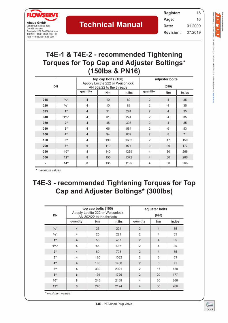
T4E-1 & T4E-2 - recommended Tightening Torques for Top Cap and Adjuster Boltings*
(150lbs & PN16)
T4E-3 - recommended Tightening Torques for Top Cap and Adjuster Boltings* (300lbs)
DN (090)
Nm in.lbs Nm in.lbs
015 ½“ 4 10 89 2 4 35
020 ¾“ 4 10 89 2 4 35
025 1“ 4 31 274 2 4 35
040 1½“ 4 31 274 2 4 35
050 2“ 4 45 398 2 4 35
080 3“ 4 66 584 2 6 53
100 4“ 4 94 832 2 8 71
150 6“ 4 190 1682 2 17 150
200 8“ 6 110 974 2 20 177
250 10“ 8 140 1239 4 30 266
300 12“ 8 155 1372 4 30 266
- 14“ 8 135 1195 4 30 266
DN (090)
Nm in.lbs Nm in.lbs
½“ 4 25 221 2 4 35
¾“ 4 25 221 2 4 35
1“ 4 55 487 2 4 35
1½“ 4 55 487 2 4 35
2“ 4 80 708 2 4 35
3“ 4 120 1062 2 6 53
4“ 4 165 1460 2 8 71
6“ 4 330 2921 2 17 150
8“ 6 195 1726 2 20 177
10“ 8 245 2168 4 30 266
12“ 8 240 2124 4 30 266
* maximum values
top cap bolts (100)Appply Loctite 222 or Weiconlock
AN 302/22 to the threadsquantity quantity
adjuster bolts
top cap bolts (100)Appply Loctite 222 or Weiconlock
AN 302/22 to the threads
adjuster bolts
* maximum values
quantity quantity
Your distribution partner:
Blindeisenweg 31 • D
-41468 Neuss • Tel.: +49 2131 / 15 39 28-0 • Fax: +49 2131 / 15 39 28-99 • info@
fergo.eu • ww
w.fergo.eu
T4E - PFA lined Plug Valve
Ahaus GmbHvon-Braun-Straße 19aD-48683 AhausPostfach 1162 D-48661 AhausTelefon: +49(0) 2561-686-100Fax: +49(0) 2561-686-200
Register: 18Page: 17Date: 01.2009Revision: 07.2019
Technical Manual
E
2
H2
C
P
GSW
J
DN
Adjustmentdown - A1
nxO
B
R
S
ØT
ØT
DN10",12"
Bracket cut
Adjustmentup - A2
ØT
X
Y
MC
GSW
J
Adjustmentdown - A1
T2(M)
DN
Z
Adjustmentup - A2
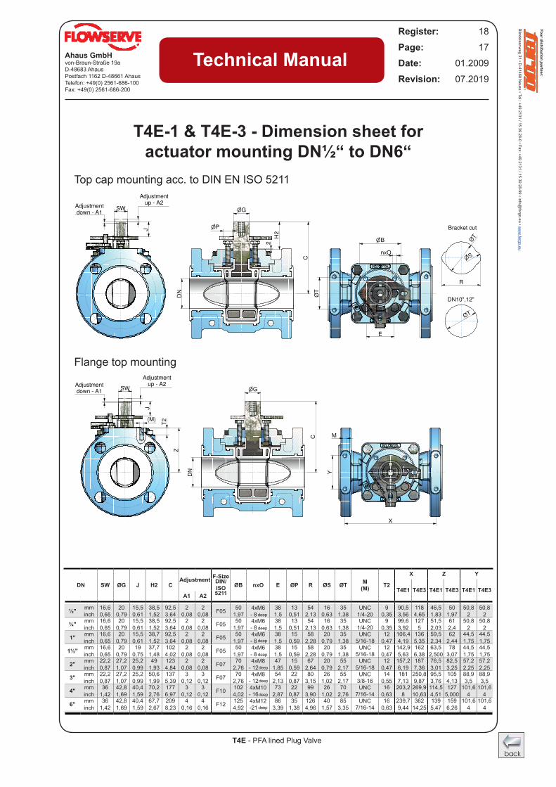
T4E-1 & T4E-3 - Dimension sheet for actuator mounting DN½“ to DN6“
Top cap mounting acc. to DIN EN ISO 5211
Flange top mounting
DN SW ØG J H2 CAdjustment F-Size
ØB nxO E ØP R ØS ØT M (M) T2
X Z YDIN/ISO T4E1 T4E3 T4E1 T4E3 T4E1 T4E3
A1 A2 5211
½" mm 16,6 20 15,5 38,5 92,5 2 2 F05 50 4xM6 - 8 tief
38 13 54 16 35 UNC 1/4-20
9 90,5 118 46,5 50 50,8 50,8inch 0,65 0,79 0,61 1,52 3,64 0,08 0,08 1,97 1,5 0,51 2,13 0,63 1,38 0,35 3,56 4,65 1,83 1,97 2 2
¾" mm 16,6 20 15,5 38,5 92,5 2 2 F05 50 4xM6 - 8 tief
38 13 54 16 35 UNC 1/4-20
9 99,6 127 51,5 61 50,8 50,8inch 0,65 0,79 0,61 1,52 3,64 0,08 0,08 1,97 1,5 0,51 2,13 0,63 1,38 0,35 3,92 5 2,03 2,4 2 2
1" mm 16,6 20 15,5 38,7 92,5 2 2 F05 50 4xM6 - 8 tief
38 15 58 20 35 UNC 5/16-18
12 106,4 136 59,5 62 44,5 44,5inch 0,65 0,79 0,61 1,52 3,64 0,08 0,08 1,97 1,5 0,59 2,28 0,79 1,38 0,47 4,19 5,35 2,34 2,44 1,75 1,75
1½" mm 16,6 20 19 37,7 102 2 2 F05 50 4xM6 - 8 tief
38 15 58 20 35 UNC 5/16-18
12 142,9 162 63,5 78 44,5 44,5inch 0,65 0,79 0,75 1,48 4,02 0,08 0,08 1,97 1,5 0,59 2,28 0,79 1,38 0,47 5,63 6,38 2,500 3,07 1,75 1,75
2" mm 22,2 27,2 25,2 49 123 2 2 F07 70 4xM8 - 12 tief
47 15 67 20 55 UNC 5/16-18
12 157,2 187 76,5 82,5 57,2 57,2inch 0,87 1,07 0,99 1,93 4,84 0,08 0,08 2,76 1,85 0,59 2,64 0,79 2,17 0,47 6,19 7,36 3,01 3,25 2,25 2,25
3" mm 22,2 27,2 25,2 50,6 137 3 3 F07 70 4xM8 - 12 tief
54 22 80 26 55 UNC 3/8-16
14 181 250,8 95,5 105 88,9 88,9inch 0,87 1,07 0,99 1,99 5,39 0,12 0,12 2,76 2,13 0,87 3,15 1,02 2,17 0,55 7,13 9,87 3,76 4,13 3,5 3,5
4" mm 36 42,8 40,4 70,2 177 3 3 F10 102 4xM10 - 16 tief
73 22 99 26 70 UNC 7/16-14
16 203,2 269,9 114,5 127 101,6 101,6inch 1,42 1,69 1,59 2,76 6,97 0,12 0,12 4,02 2,87 0,87 3,90 1,02 2,76 0,63 8 10,63 4,51 5,000 4 4
6" mm 36 42,8 40,4 67,7 209 4 4 F12 125 4xM12 -21 tief
86 35 126 40 85 UNC 7/16-14
16 239,7 362 139 159 101,6 101,6inch 1,42 1,69 1,59 2,67 8,23 0,16 0,16 4,92 3,39 1,38 4,96 1,57 3,35 0,63 9,44 14,25 5,47 6,26 4 4
deep
deep
deep
deep
deep
deep
deep
deep
Your distribution partner:
Blindeisenweg 31 • D
-41468 Neuss • Tel.: +49 2131 / 15 39 28-0 • Fax: +49 2131 / 15 39 28-99 • info@
fergo.eu • ww
w.fergo.eu
Your distribution partner:
Blindeisenweg 31 • D
-41468 Neuss • Tel.: +49 2131 / 15 39 28-0 • Fax: +49 2131 / 15 39 28-99 • info@
fergo.eu • ww
w.fergo.eu
T4E - PFA lined Plug Valve
Ahaus GmbHvon-Braun-Straße 19aD-48683 AhausPostfach 1162 D-48661 AhausTelefon: +49(0) 2561-686-100Fax: +49(0) 2561-686-200
Register: 18Page: 18Date: 01.2009Revision: 07.2019
Technical Manual
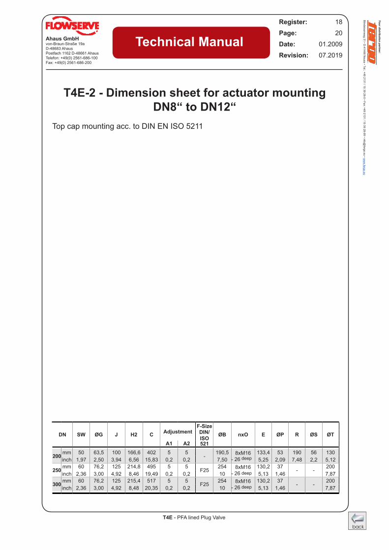
Top cap mounting acc. to DIN EN ISO 5211
Flange top mounting
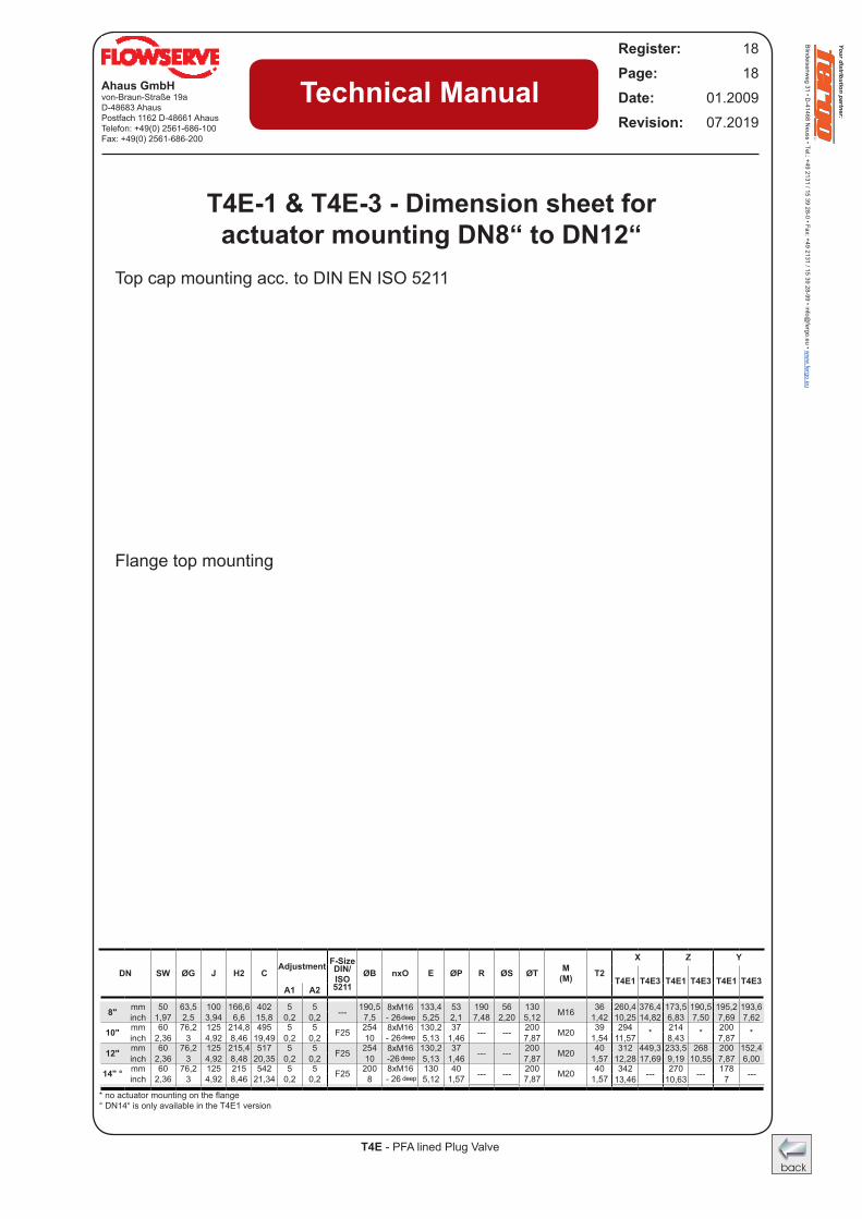
T4E-1 & T4E-3 - Dimension sheet for actuator mounting DN8“ to DN12“
DN SW ØG J H2 CAdjustment F-Size
ØB nxO E ØP R ØS ØT M (M) T2
X Z YDIN/ISO T4E1 T4E3 T4E1 T4E3 T4E1 T4E3
A1 A2 5211
8" mm 50 63,5 100 166,6 402 5 5 --- 190,5 8xM16 - 26 tief
133,4 53 190 56 130 M16 36 260,4 376,4 173,5 190,5 195,2 193,6inch 1,97 2,5 3,94 6,6 15,8 0,2 0,2 7,5 5,25 2,1 7,48 2,20 5,12 1,42 10,25 14,82 6,83 7,50 7,69 7,62
10" mm 60 76,2 125 214,8 495 5 5 F25 254 8xM16 - 26 tief
130,2 37 --- --- 200 M20 39 294 * 214 * 200 *inch 2,36 3 4,92 8,46 19,49 0,2 0,2 10 5,13 1,46 7,87 1,54 11,57 8,43 7,87
12" mm 60 76,2 125 215,4 517 5 5 F25 254 8xM16 -26 tief
130,2 37 --- --- 200 M20 40 312 449,3 233,5 268 200 152,4inch 2,36 3 4,92 8,48 20,35 0,2 0,2 10 5,13 1,46 7,87 1,57 12,28 17,69 9,19 10,55 7,87 6,00
14" ° mm 60 76,2 125 215 542 5 5 F25 200 8xM16 - 26 tief
130 40 --- --- 200 M20 40 342 --- 270 --- 178 ---inch 2,36 3 4,92 8,46 21,34 0,2 0,2 8 5,12 1,57 7,87 1,57 13,46 10,63 7
*noactuatormountingontheflange° DN14“ is only available in the T4E1 version
deep
deep
deep
deep
Your distribution partner:
Blindeisenweg 31 • D
-41468 Neuss • Tel.: +49 2131 / 15 39 28-0 • Fax: +49 2131 / 15 39 28-99 • info@
fergo.eu • ww
w.fergo.eu
T4E - PFA lined Plug Valve
Ahaus GmbHvon-Braun-Straße 19aD-48683 AhausPostfach 1162 D-48661 AhausTelefon: +49(0) 2561-686-100Fax: +49(0) 2561-686-200
Register: 18Page: 19Date: 01.2009Revision: 07.2019
Technical Manual
Top cap mounting acc. to DIN EN ISO 5211
E
2
H2
C
P
GSW
J
DN
Adjustmentdown - A1
nxO
B
R
S
ØT
ØT
DN10",12"
Bracket cut
Adjustmentup - A2
ØT
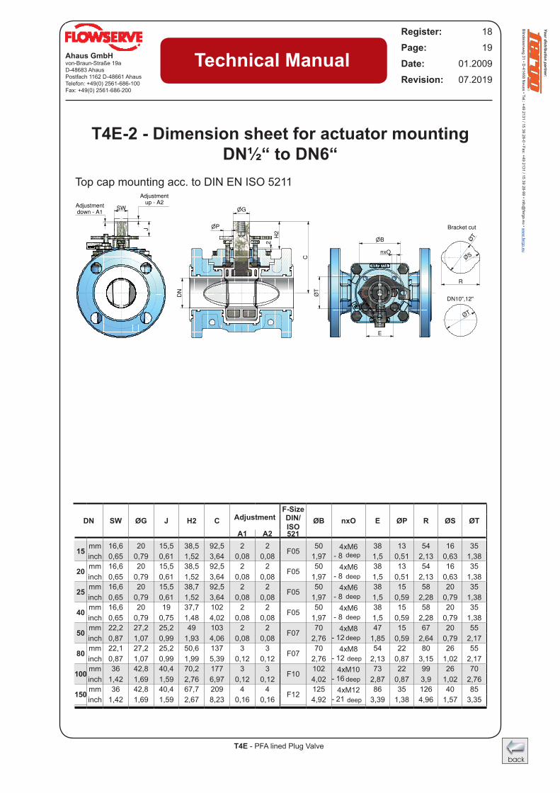
T4E-2 - Dimension sheet for actuator mounting DN½“ to DN6“
DN SW ØG J H2 C AdjustmentF-Size
ØB nxO E ØP R ØS ØTDIN/ISO
A1 A2 521
15 mm 16,6 20 15,5 38,5 92,5 2 2F05
50 4xM6 - 8_____
38 13 54 16 35inch 0,65 0,79 0,61 1,52 3,64 0,08 0,08 1,97 1,5 0,51 2,13 0,63 1,38
20 mm 16,6 20 15,5 38,5 92,5 2 2F05
50 4xM6 - 8_____
38 13 54 16 35inch 0,65 0,79 0,61 1,52 3,64 0,08 0,08 1,97 1,5 0,51 2,13 0,63 1,38
25 mm 16,6 20 15,5 38,7 92,5 2 2F05
50 4xM6 - 8_____
38 15 58 20 35inch 0,65 0,79 0,61 1,52 3,64 0,08 0,08 1,97 1,5 0,59 2,28 0,79 1,38
40 mm 16,6 20 19 37,7 102 2 2F05
50 4xM6 - 8_____
38 15 58 20 35inch 0,65 0,79 0,75 1,48 4,02 0,08 0,08 1,97 1,5 0,59 2,28 0,79 1,38
50 mm 22,2 27,2 25,2 49 103 2 2F07
70 4xM8 - 12_____
47 15 67 20 55inch 0,87 1,07 0,99 1,93 4,06 0,08 0,08 2,76 1,85 0,59 2,64 0,79 2,17
80 mm 22,1 27,2 25,2 50,6 137 3 3F07
70 4xM8 - 12_____
54 22 80 26 55inch 0,87 1,07 0,99 1,99 5,39 0,12 0,12 2,76 2,13 0,87 3,15 1,02 2,17
100 mm 36 42,8 40,4 70,2 177 3 3F10
102 4xM10 - 16_____
73 22 99 26 70inch 1,42 1,69 1,59 2,76 6,97 0,12 0,12 4,02 2,87 0,87 3,9 1,02 2,76
150 mm 36 42,8 40,4 67,7 209 4 4F12
125 4xM12 - 21_____
86 35 126 40 85inch 1,42 1,69 1,59 2,67 8,23 0,16 0,16 4,92 3,39 1,38 4,96 1,57 3,35
deep
deep
deep
deep
deep
deep
deep
deep
Your distribution partner:
Blindeisenweg 31 • D
-41468 Neuss • Tel.: +49 2131 / 15 39 28-0 • Fax: +49 2131 / 15 39 28-99 • info@
fergo.eu • ww
w.fergo.eu
Your distribution partner:
Blindeisenweg 31 • D
-41468 Neuss • Tel.: +49 2131 / 15 39 28-0 • Fax: +49 2131 / 15 39 28-99 • info@
fergo.eu • ww
w.fergo.eu
T4E - PFA lined Plug Valve
Ahaus GmbHvon-Braun-Straße 19aD-48683 AhausPostfach 1162 D-48661 AhausTelefon: +49(0) 2561-686-100Fax: +49(0) 2561-686-200
Register: 18Page: 20Date: 01.2009Revision: 07.2019
Technical Manual
Top cap mounting acc. to DIN EN ISO 5211
T4E-2 - Dimension sheet for actuator mounting DN8“ to DN12“
DN SW ØG J H2 C AdjustmentF-Size
ØB nxO E ØP R ØS ØTDIN/ISO
A1 A2 521
200 mm 50 63,5 100 166,6 402 5 5-
190,5 8xM16 - 26_____
133,4 53 190 56 130inch 1,97 2,50 3,94 6,56 15,83 0,2 0,2 7,50 5,25 2,09 7,48 2,2 5,12
250 mm 60 76,2 125 214,8 495 5 5F25
254 8xM16 - 26_____
130,2 37- -
200inch 2,36 3,00 4,92 8,46 19,49 0,2 0,2 10 5,13 1,46 7,87
300 mm 60 76,2 125 215,4 517 5 5 F25 254 8xM16 - 26_____
130,2 37 - - 200inch 2,36 3,00 4,92 8,48 20,35 0,2 0,2 10 5,13 1,46 7,87
deep
deep
deep
Your distribution partner:
Blindeisenweg 31 • D
-41468 Neuss • Tel.: +49 2131 / 15 39 28-0 • Fax: +49 2131 / 15 39 28-99 • info@
fergo.eu • ww
w.fergo.eu
T4E - PFA lined Plug Valve
Ahaus GmbHvon-Braun-Straße 19aD-48683 AhausPostfach 1162 D-48661 AhausTelefon: +49(0) 2561-686-100Fax: +49(0) 2561-686-200
Register: 18Page: 21Date: 01.2009Revision: 07.2019
Technical Manual
Size
Size
° DN14“ is only available in the T4E1 version
° DN14“ is only available in the T4E1 version
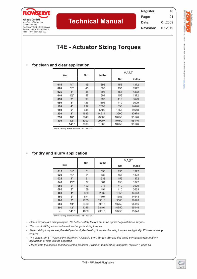
T4E - Actuator Sizing Torques
• for clean and clear application
• for dry and slurry application
Nm in/lbsMAST
Nm in/lbs
015 ½" 45 398 155 1372020 ¾" 45 398 155 1372025 1" 45 398 155 1372040 1½" 57 504 155 1372050 2" 90 797 410 3629080 3" 125 1106 410 3629100 4" 237 2098 1655 14648150 6" 645 5709 1655 14648200 8" 1685 14914 3500 30978250 10" 2640 23366 10750 95146300 12" 3300 29207 10750 95146
- 14" ° 3600 31863 10750 95146
Nm in/lbsMAST
Nm in/lbs
015 ½" 61 538 155 1372020 ¾" 61 538 155 1372025 1" 61 538 155 1372040 1½" 77 681 155 1372050 2" 122 1075 410 3629080 3" 169 1494 410 3629100 4" 320 2832 1655 14648150 6" 871 7707 1655 14648200 8" 2205 19516 3500 30978250 10" 3459 30615 10750 95146300 12" 4315 38191 10750 95146
- 14" ° 4860 43015 10750 95146
- Stated torques are sizing torques. No further safety factors are to be applied against these torques. - The use of V-Plugs does not result in change in sizing torques. - Stated sizing torques are „Break-Open“ and „Re-Seating“ torques. Running torques are typically 35% below sizing
torques.- The stated „MAST“ value is the Maximum Allowable Stem Torque. Beyond this value permanent deformation /
destruction of liner is to be expected.- Please note the service conditions of the pressure- / vacuum-temperature-diagrams: register 1, page 13.
Your distribution partner:
Blindeisenweg 31 • D
-41468 Neuss • Tel.: +49 2131 / 15 39 28-0 • Fax: +49 2131 / 15 39 28-99 • info@
fergo.eu • ww
w.fergo.eu
Your distribution partner:
Blindeisenweg 31 • D
-41468 Neuss • Tel.: +49 2131 / 15 39 28-0 • Fax: +49 2131 / 15 39 28-99 • info@
fergo.eu • ww
w.fergo.eu
T4E - PFA lined Plug Valve
Ahaus GmbHvon-Braun-Straße 19aD-48683 AhausPostfach 1162 D-48661 AhausTelefon: +49(0) 2561-686-100Fax: +49(0) 2561-686-200
Register: 18Page: 22Date: 01.2009Revision: 07.2019
Technical Manual
V - Plug
° DN14“ is only available in the T4E1 version
S - Plug
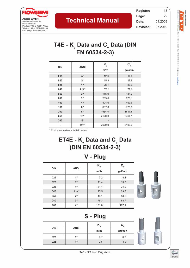
T4E - Kv Data and Cv Data (DIN EN 60534-2-3)
ET4E - Kv Data and Cv Data (DIN EN 60534-2-3)
DIN ANSIKV CV
m³/h gal/min
025 1“ 7,2 8,4
025 1“ 11,4 13,3
025 1“ 21,4 24,9
040 1 ½“ 25,5 29,6
050 2“ 46,1 53,6
080 3“ 76,3 88,7
100 4“ 161,0 187,1
DIN ANSIKV CV
m³/h gal/min
015 ½“ 12,6 14,6
020 ¾“ 15,3 17,8
025 1“ 26,1 30,3
040 1 ½“ 67,1 78,0
050 2“ 156,0 181,3
080 3“ 235,0 273,1
100 4“ 404,0 469,6
150 6“ 667,0 775,3
200 8“ 1564,0 1817,8
250 10“ 2120,0 2464,1
300 12“ - -
- 14“ ° 2670,0 3103,3
DIN ANSIKV CV
m³/h gal/min
025 1“ 0,7 0,8
025 1“ 2,6 3,0
Your distribution partner:
Blindeisenweg 31 • D
-41468 Neuss • Tel.: +49 2131 / 15 39 28-0 • Fax: +49 2131 / 15 39 28-99 • info@
fergo.eu • ww
w.fergo.eu
T4E - PFA lined Plug Valve
Ahaus GmbHvon-Braun-Straße 19aD-48683 AhausPostfach 1162 D-48661 AhausTelefon: +49(0) 2561-686-100Fax: +49(0) 2561-686-200
Register: 18Page: 23Date: 01.2009Revision: 07.2019
Technical Manual
F ( 1 / 3 )
L-L ( 1 / 3 )M-M ( 1 / 3 )
F
L
L
M
M
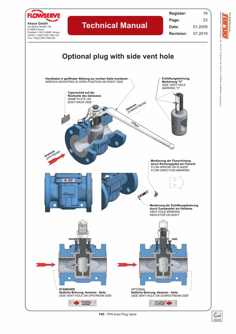
Typenschild auf der Rückseite des GehäusesNAME PLATE ON BODY BACK SIDE
Anstrom
UPSTREAM
Abstrom
DOWNSTREAM
Handhebel in geöffneter Stellung zur rechten Seite montierenWRENCH MOUNTING IN OPEN POSITION ON RIGHT SIDE
Markierung der Flussrichtungdurch Richtungspfeil am FlanschFLOW ARROW ON FLANGEFLOW DIRECTION MARKING
Markierung der Entlüftungsbohrungdurch Zusatzspfeil am GehäuseVENT HOLE MARKINGINDICATOR ON BODY
Entlüftungsbohrung,Markierung "V"SIDE VENT HOLEMARKING "V"
STANDARDSeitliche Bohrung, Anstrom - SeiteSIDE VENT HOLE ON UPSTREAM SIDE
OPTIONALSeitliche Bohrung, Abstrom - SeiteSIDE VENT HOLE ON DOWNSTREAM SIDE
Optional plug with side vent hole
Your distribution partner:
Blindeisenweg 31 • D
-41468 Neuss • Tel.: +49 2131 / 15 39 28-0 • Fax: +49 2131 / 15 39 28-99 • info@
fergo.eu • ww
w.fergo.eu
Your distribution partner:
Blindeisenweg 31 • D
-41468 Neuss • Tel.: +49 2131 / 15 39 28-0 • Fax: +49 2131 / 15 39 28-99 • info@
fergo.eu • ww
w.fergo.eu
T4E - PFA lined Plug Valve
Ahaus GmbHvon-Braun-Straße 19aD-48683 AhausPostfach 1162 D-48661 AhausTelefon: +49(0) 2561-686-100Fax: +49(0) 2561-686-200
Register: 18Page: 24Date: 01.2009Revision: 07.2019
Technical Manual
F-F ( 1 / 2 )
G-G ( 1 / 3 )
J-J ( 1 / 3 )
F
F
G
G
J
J
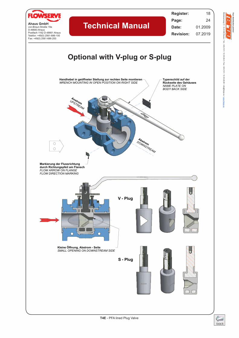
V - Plug
S - Plug
Typenschild auf der Rückseite des GehäusesNAME PLATE ON BODY BACK SIDE
Markierung der Flussrichtungdurch Richtungspfeil am FlanschFLOW ARROW ON FLANGEFLOW DIRECTION MARKING
AnstromUPSTREAM
AbstromDOWNSTREAM
Handhebel in geöffneter Stellung zur rechten Seite montierenWRENCH MOUNTING IN OPEN POSITION ON RIGHT SIDE
Kleine Öffnung, Abstrom - SeiteSMALL OPENING ON DOWNSTREAM SIDE
Optional with V-plug or S-plug
Your distribution partner:
Blindeisenweg 31 • D
-41468 Neuss • Tel.: +49 2131 / 15 39 28-0 • Fax: +49 2131 / 15 39 28-99 • info@
fergo.eu • ww
w.fergo.eu