Embed Size (px)
Citation preview

Reinforcement Design
V1.0
User manual

Reinforcement Design
V1.0
User Manual Page 2 / 31
Reinforcement Design
V1.0
User Manual Page 3 / 31
Summary
Reinforcement Design is an ACT application to extend the capabilities of ANSYS for the
computation of reinforcement ratios of concrete structures (such as slabs, walls, ...) modeled
with shell or plate elements.
The extension will:
1. Define combinations of load cases;
2. Combine internal forces using these combinations;
3. Compute reinforcement ratios.
The extension is designed to post-process finite element analyses using Ansys Mechanical in a
Workbench environment.
Reinforcement Design
V1.0
User Manual Page 4 / 31
Contents
1. Reinforcement Design Analysis ....................................................................................... 5
1.1. Analysis settings ..................................................................................................................................................... 5
2. Define combinations of load cases ................................................................................... 7
2.1. Defining a Load Case ............................................................................................................................................ 7
2.2. Defining a Combination ........................................................................................................................................ 9
2.3. Defining a Group ................................................................................................................................................. 10
2.4. Defining a Combinations Group ......................................................................................................................... 14
3. Define the parameters of the post-processing .............................................................. 15
3.1. Element Parameter .............................................................................................................................................. 15
3.2. Concrete ............................................................................................................................................................... 17
3.3. Transverse Reinforcement ................................................................................................................................... 19
3.4. Longitudinal Reinforcement ................................................................................................................................ 20
4. Element coordinate systems ........................................................................................... 22
5. Reinforcement Design results ........................................................................................ 23
5.1. Reinforcement Areas ............................................................................................................................................ 23
5.2. Concrete Stress ..................................................................................................................................................... 24
6. Limitations ....................................................................................................................... 26
7. Annex 1: How to use rst files to create a Static Structural analysis ........................... 27
Reinforcement Design
V1.0
User Manual Page 5 / 31
1. Reinforcement Design Analysis
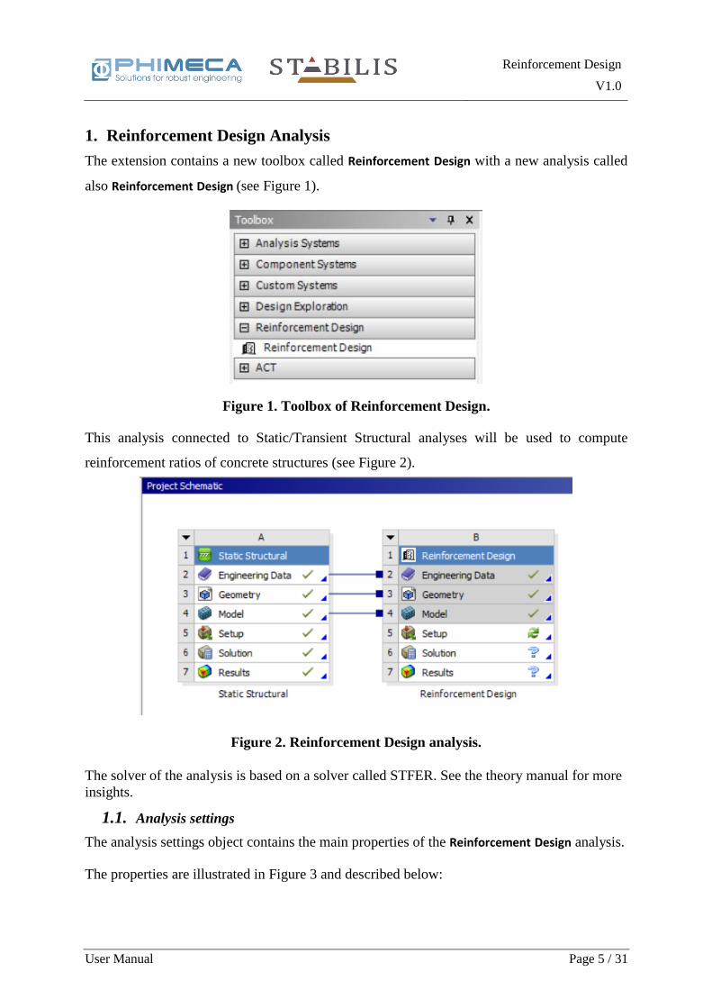
The extension contains a new toolbox called Reinforcement Design with a new analysis called
also Reinforcement Design (see Figure 1).
This analysis connected to Static/Transient Structural analyses will be used to compute
reinforcement ratios of concrete structures (see Figure 2).
The solver of the analysis is based on a solver called STFER. See the theory manual for more
insights.
1.1. Analysis settings
The analysis settings object contains the main properties of the Reinforcement Design analysis.
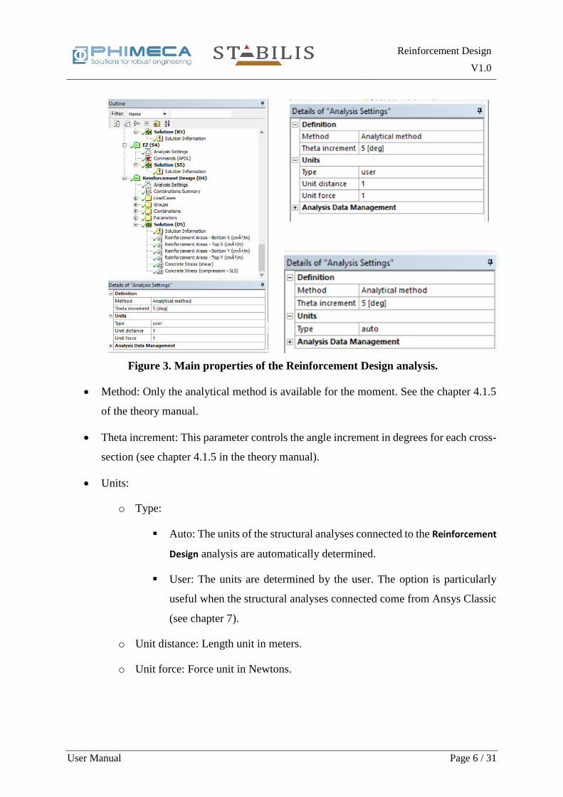
The properties are illustrated in Figure 3 and described below:
Figure 1. Toolbox of Reinforcement Design.
Figure 2. Reinforcement Design analysis.
Reinforcement Design
V1.0
User Manual Page 6 / 31
• Method: Only the analytical method is available for the moment. See the chapter 4.1.5
of the theory manual.
• Theta increment: This parameter controls the angle increment in degrees for each cross-
section (see chapter 4.1.5 in the theory manual).
• Units:
o Type:
▪ Auto: The units of the structural analyses connected to the Reinforcement
Design analysis are automatically determined.
▪ User: The units are determined by the user. The option is particularly
useful when the structural analyses connected come from Ansys Classic
(see chapter 7).
o Unit distance: Length unit in meters.
o Unit force: Force unit in Newtons.
Figure 3. Main properties of the Reinforcement Design analysis.
Reinforcement Design
V1.0
User Manual Page 7 / 31
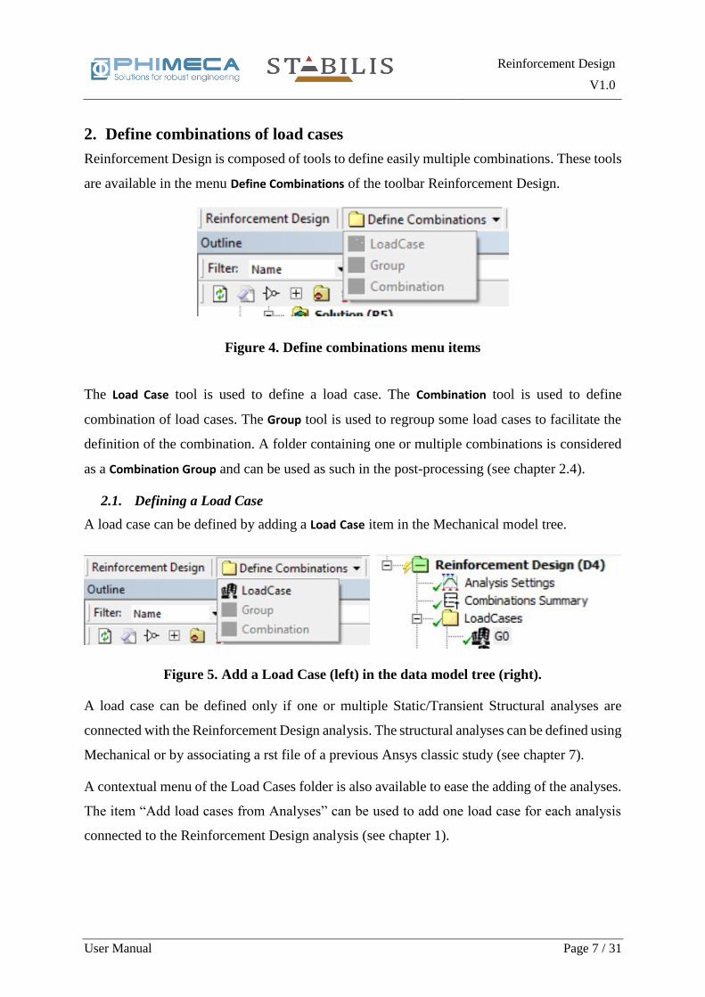
2. Define combinations of load cases
Reinforcement Design is composed of tools to define easily multiple combinations. These tools
are available in the menu Define Combinations of the toolbar Reinforcement Design.
The Load Case tool is used to define a load case. The Combination tool is used to define
combination of load cases. The Group tool is used to regroup some load cases to facilitate the
definition of the combination. A folder containing one or multiple combinations is considered
as a Combination Group and can be used as such in the post-processing (see chapter 2.4).
2.1. Defining a Load Case
A load case can be defined by adding a Load Case item in the Mechanical model tree.
A load case can be defined only if one or multiple Static/Transient Structural analyses are
connected with the Reinforcement Design analysis. The structural analyses can be defined using
Mechanical or by associating a rst file of a previous Ansys classic study (see chapter 7).
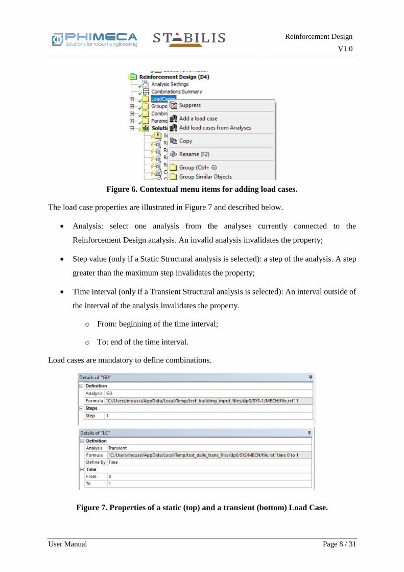
A contextual menu of the Load Cases folder is also available to ease the adding of the analyses.
The item “Add load cases from Analyses” can be used to add one load case for each analysis
connected to the Reinforcement Design analysis (see chapter 1).
Figure 4. Define combinations menu items
Figure 5. Add a Load Case (left) in the data model tree (right).
Reinforcement Design
V1.0
User Manual Page 8 / 31
The load case properties are illustrated in Figure 7 and described below.
• Analysis: select one analysis from the analyses currently connected to the
Reinforcement Design analysis. An invalid analysis invalidates the property;
• Step value (only if a Static Structural analysis is selected): a step of the analysis. A step
greater than the maximum step invalidates the property;
• Time interval (only if a Transient Structural analysis is selected): An interval outside of
the interval of the analysis invalidates the property.
o From: beginning of the time interval;
o To: end of the time interval.
Load cases are mandatory to define combinations.
Figure 6. Contextual menu items for adding load cases.
Figure 7. Properties of a static (top) and a transient (bottom) Load Case.

Reinforcement Design
V1.0
User Manual Page 9 / 31
2.2. Defining a Combination
The Combination item is used to define a combination of load cases.
The combination properties are illustrated in Figure 9 and described below.
• A read-only property displaying the formula of the combination;
• A type (Ultimate Limit State or Serviceability Limit State);
• A button to open a window used to define the combination formula.
Figure 8. Add a Combination (left) in the data model tree (right).
Figure 9. Properties of a Combination.
Figure 10. Combination formula definition window.

Reinforcement Design
V1.0
User Manual Page 10 / 31
The combination in Figure 10 is a mathematical formula combining load cases and optionally
groups (see 2.3).
𝐶𝐵 = 𝑓(𝐿𝐶1, … , 𝐿𝐶𝑛, 𝐺𝑅1, … , 𝐺𝑅𝑚 )
With 𝐿𝐶𝑗 as load cases, and 𝐺𝑅𝑙 as groups and 𝑓 as a linear function. If the characters +/− are
used it means that the positive and negative term will be used to define the combination and if
there is a parenthesis it means that the coefficient zero is also possible.
Some examples of combinations:
𝐶𝐵1 = 2 𝐿𝐶1 + 5 𝐺𝑅1
𝐶𝐵2 = 3 𝐶𝐵1 + +/− 3 𝐿𝐶2
At least one Combination should be defined to solve the Reinforcement Design analysis.
2.3. Defining a Group
The group is an intermediate between a load case and combination and can be used to clarify
the formula of a combination.
Groups are optional to define combinations.
The group properties are illustrated in Figure 12 and described below.
Figure 11. Add a Group (left) in the data model tree (right).
Figure 12. Properties of a Group.
Reinforcement Design
V1.0
User Manual Page 11 / 31
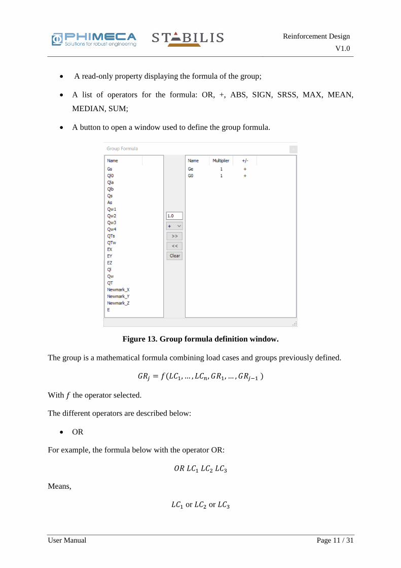
• A read-only property displaying the formula of the group;
• A list of operators for the formula: OR, +, ABS, SIGN, SRSS, MAX, MEAN,
MEDIAN, SUM;
• A button to open a window used to define the group formula.
The group is a mathematical formula combining load cases and groups previously defined.
𝐺𝑅𝑗 = 𝑓(𝐿𝐶1, … , 𝐿𝐶𝑛, 𝐺𝑅1, … , 𝐺𝑅𝑗−1 )
With 𝑓 the operator selected.
The different operators are described below:
• OR
For example, the formula below with the operator OR:
𝑂𝑅 𝐿𝐶1 𝐿𝐶2 𝐿𝐶3
Means,
𝐿𝐶1 or 𝐿𝐶2 or 𝐿𝐶3
Figure 13. Group formula definition window.
Reinforcement Design
V1.0
User Manual Page 12 / 31
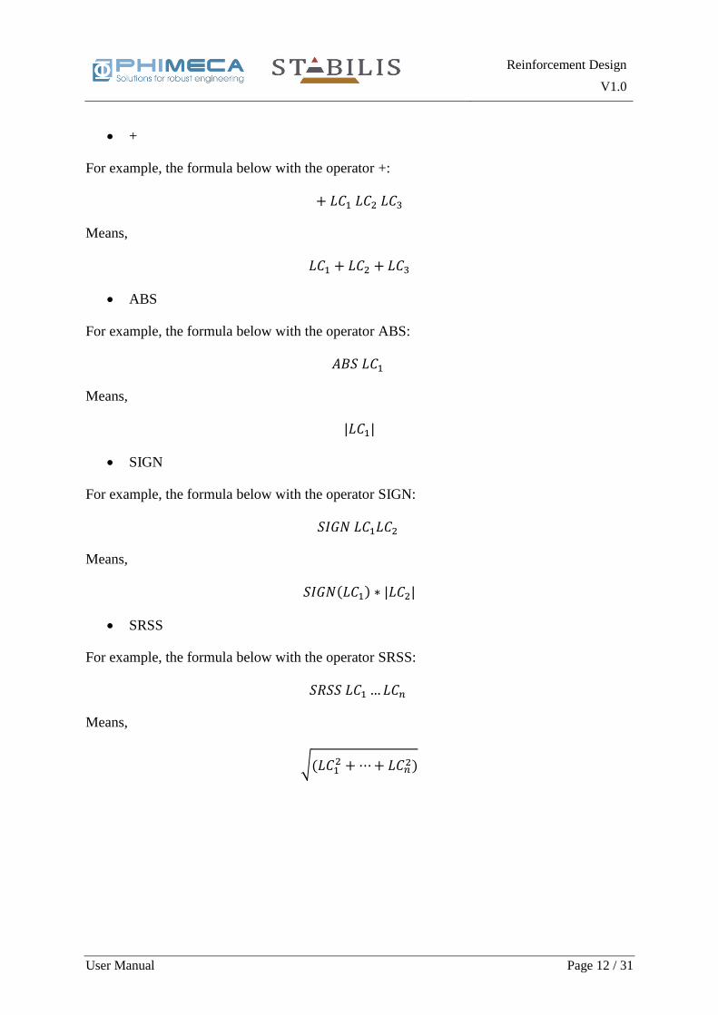
• +
For example, the formula below with the operator +:
+ 𝐿𝐶1 𝐿𝐶2 𝐿𝐶3
Means,
𝐿𝐶1 + 𝐿𝐶2 + 𝐿𝐶3
• ABS
For example, the formula below with the operator ABS:
𝐴𝐵𝑆 𝐿𝐶1
Means,
|𝐿𝐶1|
• SIGN
For example, the formula below with the operator SIGN:
𝑆𝐼𝐺𝑁 𝐿𝐶1𝐿𝐶2
Means,
𝑆𝐼𝐺𝑁(𝐿𝐶1) ∗ |𝐿𝐶2|
• SRSS
For example, the formula below with the operator SRSS:
𝑆𝑅𝑆𝑆 𝐿𝐶1 …𝐿𝐶𝑛
Means,
√(𝐿𝐶12 + ⋯+ 𝐿𝐶𝑛
2)
Reinforcement Design
V1.0
User Manual Page 13 / 31
The following groups (MAX, MEAN, MEDIAN, SUM) can be used only for time history
analyses or SUM groups:
• MAX
For example, the formula below with the operator MAX:
𝑀𝐴𝑋 𝐿𝐶1 …𝐿𝐶𝑛
Computes both
max1≤𝑗≤𝑛
(max𝑡
𝐿𝐶𝑗(𝑡)) and min1≤𝑗≤𝑛
(min𝑡
𝐿𝐶𝑗(𝑡))
• MEAN
For example, the formula below with the operator MEAN:
𝑀𝐸𝐴𝑁 𝐿𝐶1 …𝐿𝐶𝑛
The MEAN operator retains the average of the maximum time history values, and the average
of the minimum time history values.
moy1≤𝑗≤𝑛
(max𝑡
𝐿𝐶𝑗(𝑡)) and moy1≤𝑗≤𝑛
(min𝑡
𝐿𝐶𝑗(𝑡))
• MEDIAN
For example, the formula below with the operator MEDIAN:
𝑀𝐸𝐷𝐼𝐴𝑁 𝐿𝐶1 …𝐿𝐶𝑛
The MEDIAN operator retains the median of the maximum time history values, and the median
of the minimum time history values.
median1≤𝑗≤𝑛
(max𝑡
𝐿𝐶𝑗(𝑡)) and median1≤𝑗≤𝑛
(min𝑡
𝐿𝐶𝑗(𝑡))
• SUM
For example, the formula below with the operator SUM:
𝑆𝑈𝑀 𝐿𝐶1 …𝐿𝐶𝑛
The SUM operator is used to sum the time histories time step by time step:
∑𝐿𝐶𝑗(𝑡)
𝑛
𝑗=1
Reinforcement Design
V1.0
User Manual Page 14 / 31
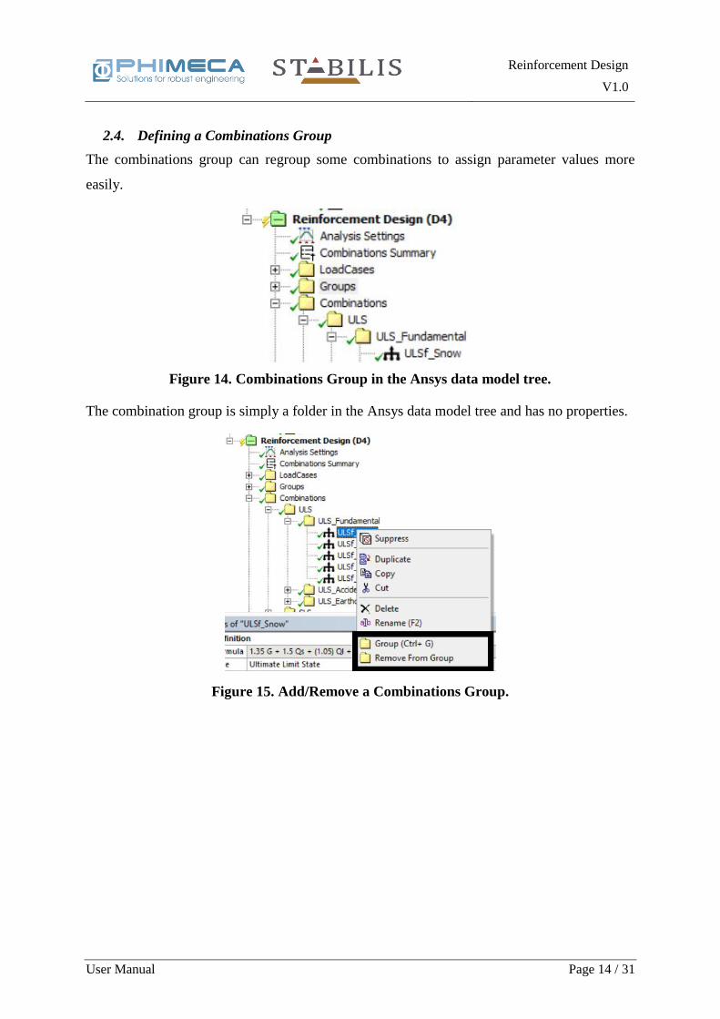
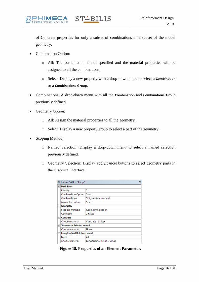
2.4. Defining a Combinations Group
The combinations group can regroup some combinations to assign parameter values more
easily.
The combination group is simply a folder in the Ansys data model tree and has no properties.
Figure 15. Add/Remove a Combinations Group.
Figure 14. Combinations Group in the Ansys data model tree.

Reinforcement Design
V1.0
User Manual Page 15 / 31
3. Define the parameters of the post-processing
The parameters assign material properties values to Combination or Combinations Group
associate with a part of the geometry. The material properties can be defined using Concrete,
Longitudinal Reinforcement and Transverse Reinforcement objects.
3.1. Element Parameter
The Element Parameter assigns the material properties values globally or to one specific
Combination or Combinations Group and to all or a part of the geometry.
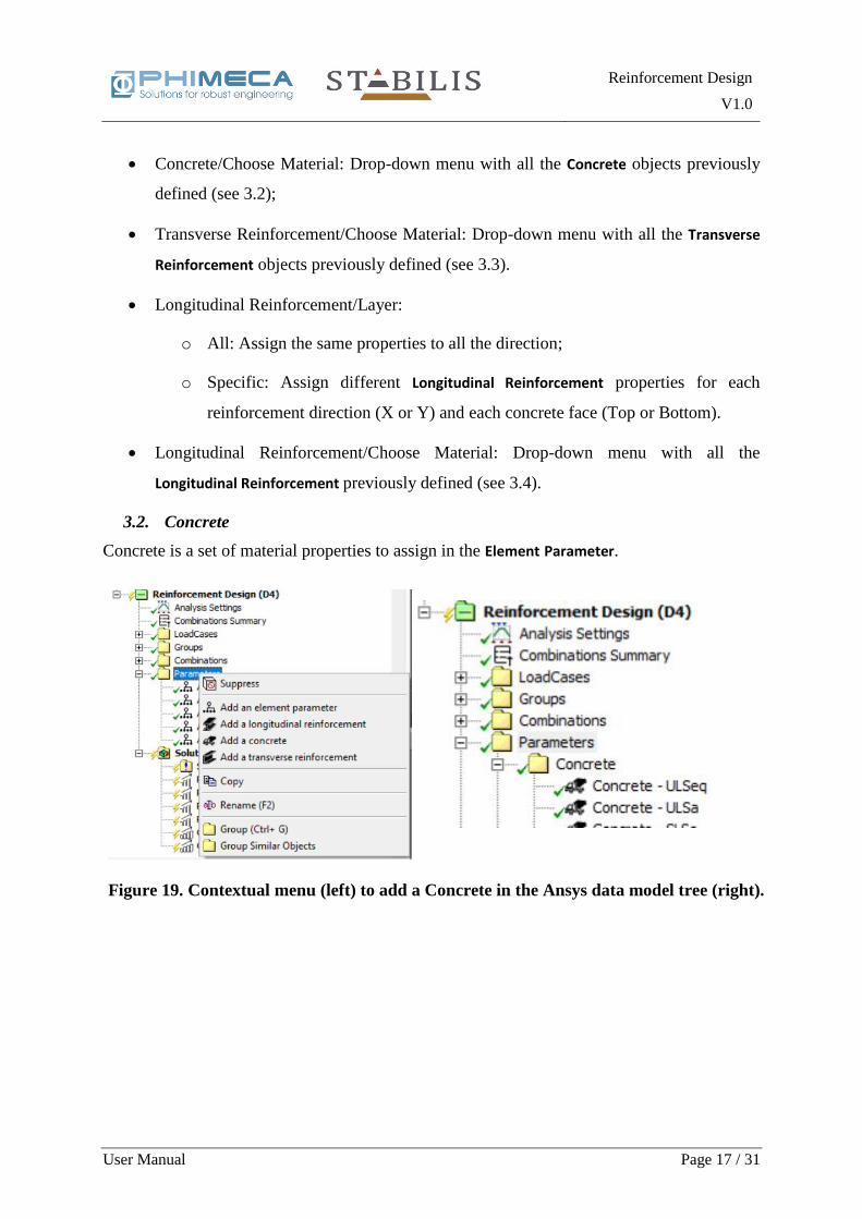
The Element Parameter properties are illustrated in Figure 18 and described below.
• Priority of the set of parameters. The material properties can be defined multiple times
so the priority indicate which one has priority. They are applied in priority order:
number 1 first, then number 2, then number 3, etc. For example, you can assign a set of
Concrete properties for the whole model and all combinations, then reassign another set
Figure 16. The menu to define material parameters.
Figure 17. The contextual menu (left) to add an Element Parameter in the Ansys
data model tree (right).
Reinforcement Design
V1.0
User Manual Page 16 / 31
of Concrete properties for only a subset of combinations or a subset of the model
geometry.
• Combination Option:
o All: The combination is not specified and the material properties will be
assigned to all the combinations;
o Select: Display a new property with a drop-down menu to select a Combination
or a Combinations Group.
• Combinations: A drop-down menu with all the Combination and Combinations Group
previously defined.
• Geometry Option:
o All: Assign the material properties to all the geometry.
o Select: Display a new property group to select a part of the geometry.
• Scoping Method:
o Named Selection: Display a drop-down menu to select a named selection
previously defined.
o Geometry Selection: Display apply/cancel buttons to select geometry parts in
the Graphical interface.
Figure 18. Properties of an Element Parameter.
Reinforcement Design
V1.0
User Manual Page 17 / 31
• Concrete/Choose Material: Drop-down menu with all the Concrete objects previously
defined (see 3.2);
• Transverse Reinforcement/Choose Material: Drop-down menu with all the Transverse
Reinforcement objects previously defined (see 3.3).
• Longitudinal Reinforcement/Layer:
o All: Assign the same properties to all the direction;
o Specific: Assign different Longitudinal Reinforcement properties for each
reinforcement direction (X or Y) and each concrete face (Top or Bottom).
• Longitudinal Reinforcement/Choose Material: Drop-down menu with all the
Longitudinal Reinforcement previously defined (see 3.4).
3.2. Concrete
Concrete is a set of material properties to assign in the Element Parameter.
Figure 19. Contextual menu (left) to add a Concrete in the Ansys data model tree (right).
.

Reinforcement Design
V1.0
User Manual Page 18 / 31
The Concrete properties are illustrated in Figure 20 and described below. These properties
define the behaviour laws of concrete to use in the post-processing. The behavior laws used in
the program are defined in Theory Manual chapter 4.2.4.
• Compressive Strength: Defines the characteristic resistance of concrete in compression
(noted 𝑓𝑐𝑘 in Eurocode 2), before application of the safety factor;
• Safety factor: Coefficient by which the compressive strength is divided in order to
obtain the design compressive strength of concrete. With Eurocode 2 notations the
safety factor is noted 𝛾𝑐, and so the design compressive strength is 𝑓𝑐𝑑 = 𝑓𝑐𝑘/𝛾𝑐. This
notation is used both for Ultimate Limit State and Serviceability Limit State.
• The type of the combination which the properties will be applied:
o All: All types of combination
o Serviceability Limit State: the properties will be applied only for combinations
with this type.
o Ultimate Limite State: the properties will be applied only for combinations with
this type.
• Equivalence coefficient (only for Serviceability Limit State combination type): the ratio
of concrete effective Young’s modulus to steel Young’s modulus, 𝑛 = 𝐸𝑐,𝑒𝑓𝑓/𝐸𝑠;
• Eps_cu2 (only for Ultimate Limite State): Ultimate strain of concrete in compression
(𝜀𝑐𝑢2).
Figure 20. Properties of Concrete.

Reinforcement Design
V1.0
User Manual Page 19 / 31
3.3. Transverse Reinforcement
Transverse Reinforcement is a set of material properties to assign in the Element Parameter.
The Transverse Reinforcement properties are illustrated in Figure 22 and described below. The
equations used in the program to compute necessary transverse reinforcements are described
with more details in Theory Manual chapter 5.2.
• Design Yield Stress: Defines the design value of the limit of elasticity of transverse
reinforcements. This value should include the partial safety coefficient if applicable;
• Transverse Redistribution:
o Slab with transverse redistribution;
o Beam or Slab without transverse redistribution;
o Wall
• Method Calculation for 𝜈1(for details see Theory Manual chapter 5.2.3.1):
Figure 21. Contextual menu (left) to add a Transverse Reinforcement in the Ansys
data model tree (right).
Figure 22. Properties of Transverse Reinforcement.
Reinforcement Design
V1.0
User Manual Page 20 / 31
o Equal to 𝜈: 𝜈1 = 𝜈;
o Alternative method: Calculating 𝜈 according to the formula (6.10aN), which
also implies the application of a fixed coefficient 0.8 to 𝑓𝑦𝑤𝑘 in the formula (6.8).
(Practical interest: increase 𝑉𝑅𝑑,𝑚𝑎𝑥 at the cost of a larger rebar section.) In case
this parameter is activated, the program applies the reduction coefficient to 𝑓𝑦𝑤𝑘.
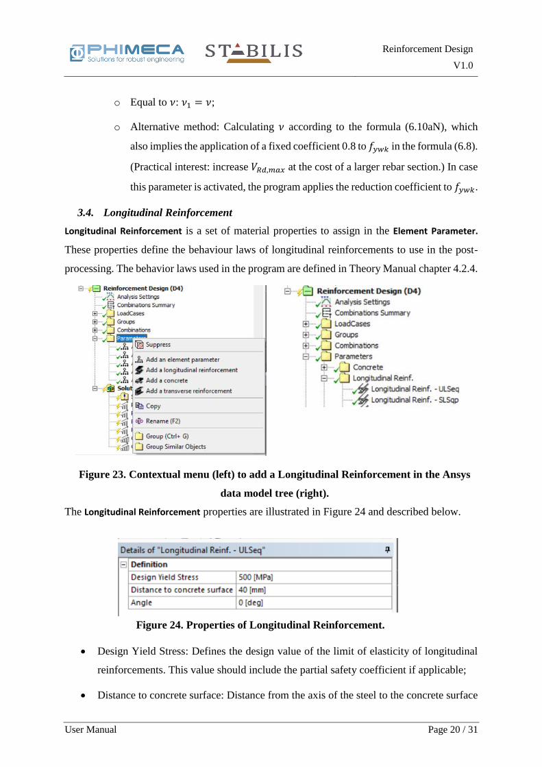
3.4. Longitudinal Reinforcement
Longitudinal Reinforcement is a set of material properties to assign in the Element Parameter.
These properties define the behaviour laws of longitudinal reinforcements to use in the post-
processing. The behavior laws used in the program are defined in Theory Manual chapter 4.2.4.
The Longitudinal Reinforcement properties are illustrated in Figure 24 and described below.
• Design Yield Stress: Defines the design value of the limit of elasticity of longitudinal
reinforcements. This value should include the partial safety coefficient if applicable;
• Distance to concrete surface: Distance from the axis of the steel to the concrete surface
Figure 23. Contextual menu (left) to add a Longitudinal Reinforcement in the Ansys
data model tree (right).
Figure 24. Properties of Longitudinal Reinforcement.
Reinforcement Design
V1.0
User Manual Page 21 / 31
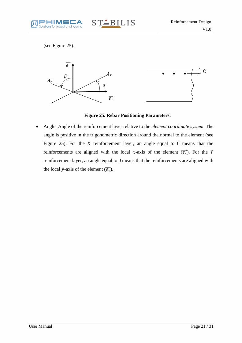
(see Figure 25).
• Angle: Angle of the reinforcement layer relative to the element coordinate system. The
angle is positive in the trigonometric direction around the normal to the element (see
Figure 25). For the 𝑋 reinforcement layer, an angle equal to 0 means that the
reinforcements are aligned with the local 𝑥-axis of the element (𝑒𝑥 ). For the 𝑌
reinforcement layer, an angle equal to 0 means that the reinforcements are aligned with
the local 𝑦-axis of the element (𝑒𝑦 ).
C 𝛽
𝛼
𝐴𝑋
𝐴𝑌
𝑒𝑦
𝑒𝑥
Figure 25. Rebar Positioning Parameters.
Reinforcement Design
V1.0
User Manual Page 22 / 31
4. Element coordinate systems
The Reinforcement Design extension operates in the element coordinate system and doesn’t
reorient the elements. Notations are as follows:
• X is used to refer to the local x axis of the element;
• Y for the local y axis of the element;
• Z for the local z axis of the element (positive towards element normal);
• Top and Bottom reinforcement layers are defined in reference to the local z axis.
Reinforcement Design
V1.0
User Manual Page 23 / 31
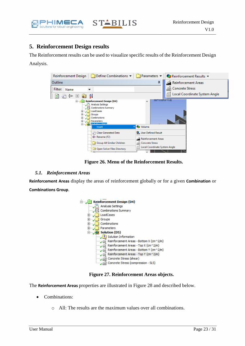
5. Reinforcement Design results
The Reinforcement results can be used to visualize specific results of the Reinforcement Design
Analysis.
5.1. Reinforcement Areas
Reinforcement Areas display the areas of reinforcement globally or for a given Combination or
Combinations Group.
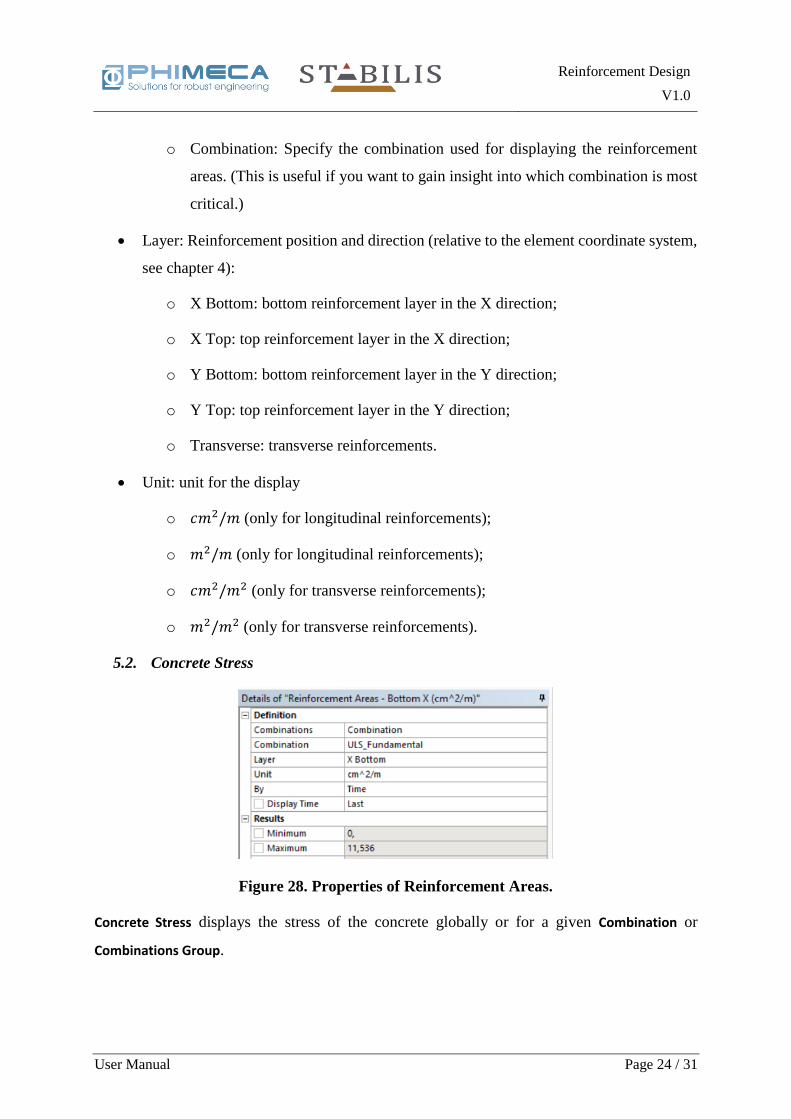
The Reinforcement Areas properties are illustrated in Figure 28 and described below.
• Combinations:
o All: The results are the maximum values over all combinations.
Figure 26. Menu of the Reinforcement Results.
Figure 27. Reinforcement Areas objects.
Reinforcement Design
V1.0
User Manual Page 24 / 31
o Combination: Specify the combination used for displaying the reinforcement
areas. (This is useful if you want to gain insight into which combination is most
critical.)
• Layer: Reinforcement position and direction (relative to the element coordinate system,
see chapter 4):
o X Bottom: bottom reinforcement layer in the X direction;
o X Top: top reinforcement layer in the X direction;
o Y Bottom: bottom reinforcement layer in the Y direction;
o Y Top: top reinforcement layer in the Y direction;
o Transverse: transverse reinforcements.
• Unit: unit for the display
o 𝑐𝑚2/𝑚 (only for longitudinal reinforcements);
o 𝑚2/𝑚 (only for longitudinal reinforcements);
o 𝑐𝑚2/𝑚2 (only for transverse reinforcements);
o 𝑚2/𝑚2 (only for transverse reinforcements).
5.2. Concrete Stress
Concrete Stress displays the stress of the concrete globally or for a given Combination or
Combinations Group.
Figure 28. Properties of Reinforcement Areas.
Reinforcement Design
V1.0
User Manual Page 25 / 31
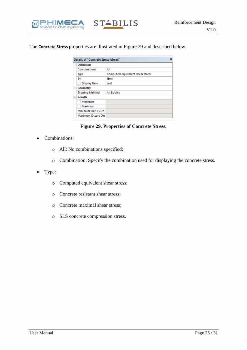
The Concrete Stress properties are illustrated in Figure 29 and described below.
• Combinations:
o All: No combinations specified;
o Combination: Specify the combination used for displaying the concrete stress.
• Type:
o Computed equivalent shear stress;
o Concrete resistant shear stress;
o Concrete maximal shear stress;
o SLS concrete compression stress.
Figure 29. Properties of Concrete Stress.

Reinforcement Design
V1.0
User Manual Page 26 / 31
6. Limitations
The following restrictions on usage of the extension apply:
• The extension is supported on Windows platform only.
• Supported elements are current-technology Structural Shell elements (SHELL181 or
SHELL281). Other types of elements such as Solid elements, Solid Shell elements,
Beam elements, etc. are not supported.
• General Miscellaneous solution must be enabled in your static and time history
analyses.
• Element coordinate system must be defined either by a cartesian coordinate system, or
by the geometry of each element. Cylindrical, spherical and toroidal coordinate systems
are not supported. We recommend using cartesian coordinate systems for better control
of the results.
• Model units can be any of the unit systems predefined in Mechanical.
• If the extension is connected to several analyses, they must all share the same model.

Reinforcement Design
V1.0
User Manual Page 27 / 31
7. Appendix 1: How to use rst files to create a Static Structural analysis
The Reinforcement Design analysis can be used with Ansys Classic studies by creating fake
Static Structural Analysis and connect them altogether.
The following files are needed to create a new Static Structural Analysis:
• rst file
• .err file (with the same name as the .rst file)
• cdb file
Follow the steps below to define the Static Structural Analysis:
• Add an External Model to the Ansys Workbench project page;
• Double click on Setup and add the cdb file;
Figure 30. External Model (right) from the Component Systems Toolbox (left).
Figure 31. External Model Setup Page.
Reinforcement Design
V1.0
User Manual Page 28 / 31
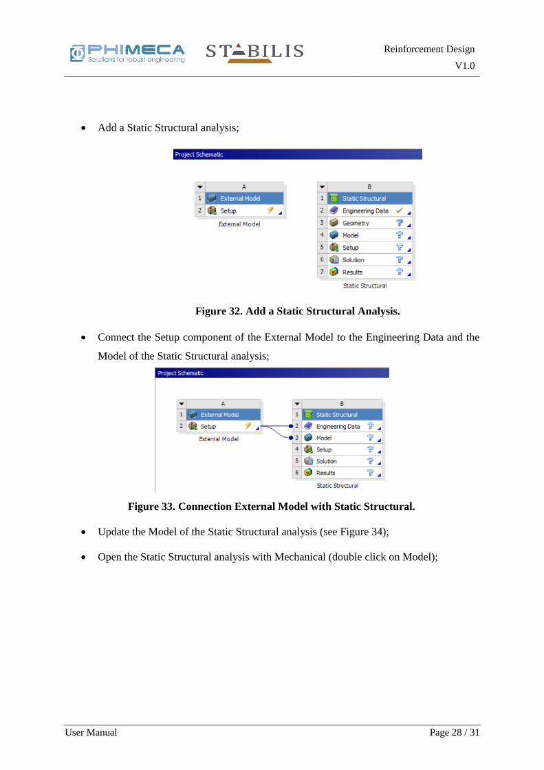
• Add a Static Structural analysis;
• Connect the Setup component of the External Model to the Engineering Data and the
Model of the Static Structural analysis;
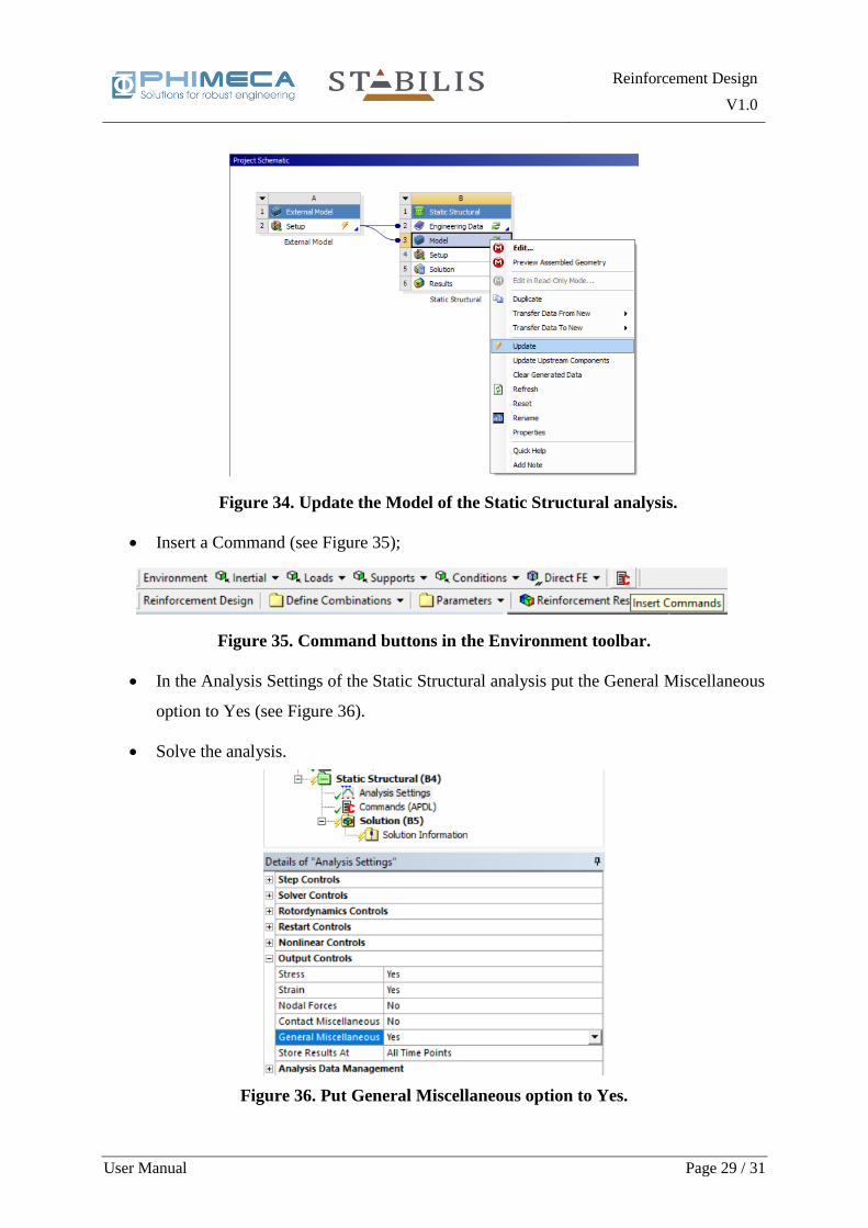
• Update the Model of the Static Structural analysis (see Figure 34);
• Open the Static Structural analysis with Mechanical (double click on Model);
Figure 32. Add a Static Structural Analysis.
Figure 33. Connection External Model with Static Structural.
Reinforcement Design
V1.0
User Manual Page 29 / 31
• Insert a Command (see Figure 35);
• In the Analysis Settings of the Static Structural analysis put the General Miscellaneous
option to Yes (see Figure 36).
• Solve the analysis.
Figure 35. Command buttons in the Environment toolbar.
Figure 34. Update the Model of the Static Structural analysis.
Figure 36. Put General Miscellaneous option to Yes.
Reinforcement Design
V1.0
User Manual Page 30 / 31
Figures
Figure 1. Toolbox of Reinforcement Design. ............................................................................ 5
Figure 2. Reinforcement Design analysis. ................................................................................. 5
Figure 3. Main properties of the Reinforcement Design analysis. ............................................. 6
Figure 4. Define combinations menu items ............................................................................... 7
Figure 5. Add a Load Case (left) in the data model tree (right). ................................................ 7
Figure 6. Contextual menu items for adding load cases. ........................................................... 8
Figure 7. Properties of a static (top) and a transient (bottom) Load Case. ................................. 8
Figure 8. Add a Combination (left) in the data model tree (right). ............................................ 9
Figure 9. Properties of a Combination. ...................................................................................... 9
Figure 10. Combination formula definition window. ................................................................ 9
Figure 11. Add a Group (left) in the data model tree (right). ................................................... 10
Figure 12. Properties of a Group. ............................................................................................. 10
Figure 13. Group formula definition window. ......................................................................... 11
Figure 14. Combinations Group in the Ansys data model tree. ............................................... 14
Figure 15. Add/Remove a Combinations Group. ..................................................................... 14
Figure 16. The menu to define material parameters. ................................................................ 15
Figure 17. The contextual menu (left) to add an Element Parameter in the Ansys data model
tree (right). ................................................................................................................................ 15
Figure 18. Properties of an Element Parameter. ....................................................................... 16
Figure 19. Contextual menu (left) to add a Concrete in the Ansys data model tree (right). .... 17
Figure 20. Properties of Concrete. ........................................................................................... 18
Figure 21. Contextual menu (left) to add a Transverse Reinforcement in the Ansys data model
tree (right). ................................................................................................................................ 19
Figure 22. Properties of Transverse Reinforcement. ................................................................ 19
Reinforcement Design
V1.0
User Manual Page 31 / 31
Figure 23. Contextual menu (left) to add a Longitudinal Reinforcement in the Ansys data model
tree (right). ................................................................................................................................ 20
Figure 24. Properties of Longitudinal Reinforcement. ............................................................ 20
Figure 25. Rebar Positioning Parameters. ................................................................................ 21
Figure 26. Menu of the Reinforcement Results. ...................................................................... 23
Figure 27. Reinforcement Areas objects. ................................................................................. 23
Figure 28. Properties of Reinforcement Areas. ........................................................................ 24
Figure 29. Properties of Concrete Stress. ................................................................................. 25
Figure 30. External Model (right) from the Component Systems Toolbox (left). ................... 27
Figure 31. External Model Setup Page. .................................................................................... 27
Figure 32. Add a Static Structural Analysis. ............................................................................ 28
Figure 33. Connection External Model with Static Structural. ................................................ 28
Figure 34. Update the Model of the Static Structural analysis. ................................................ 29
Figure 35. Command buttons in the Environment toolbar. ...................................................... 29
Figure 36. Put General Miscellaneous option to Yes. .............................................................. 29


![Reinforcement Learning or Active Inference?karl/Reinforcement... · reinforcement learning models like the Rescorla-Wagner model [1]; in computational neuroscience and machine-learning](https://img.pdfslide.net/doc/110x75/5fa189d67ffd4303373c4ff4/reinforcement-learning-or-active-inference-karlreinforcement-reinforcement.jpg)