Embed Size (px)
Citation preview

Report for Shamsher Prakash Foundation
Swarm Robots for Autonomous Trash and Garbage Removal
Pulkit Gupta
Souvik Roy
Marut Shukla
B.Tech 3rd year
Indian Institute of Technology Roorkee
The “Hexagon” Swarm Robot during testing
The “Hexagon” and “Trapezium” robots
Table of Contents
1. Abstract
2. Introduction
3. Key features
4. Design and Working
4.1 Mechanical Platform
4.2 Electronic Hardware
4.3 Software Design
5. Simulations and Testing
6. The Modular Design Concept
7. Conclusion and Further Endeavour
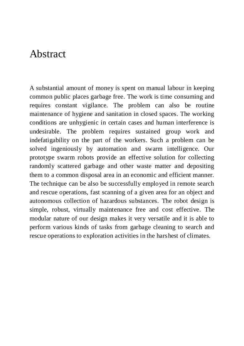
Abstract
A substantial amount of money is spent on manual labour in keeping
common public places garbage free. The work is time consuming and
requires constant vigilance. The problem can also be routine
maintenance of hygiene and sanitation in closed spaces. The working
conditions are unhygienic in certain cases and human interference is
undesirable. The problem requires sustained group work and
indefatigability on the part of the workers. Such a problem can be
solved ingeniously by automation and swarm intelligence. Our
prototype swarm robots provide an effective solution for collecting
randomly scattered garbage and other waste matter and depositing
them to a common disposal area in an economic and efficient manner.
The technique can be also be successfully employed in remote search
and rescue operations, fast scanning of a given area for an object and
autonomous collection of hazardous substances. The robot design is
simple, robust, virtually maintenance free and cost effective. The
modular nature of our design makes it very versatile and it is able to
perform various kinds of tasks from garbage cleaning to search and
rescue operations to exploration activities in the harshest of climates.
Introduction
Swarm robotics is the study of how large number of relatively simple physically
embodied agents can be designed such that a desired collective behavior
emerges from the local interactions among agents and between the agents and
the environment. It is a novel approach to the coordination of large numbers of
robots. It is inspired from the observation of social insects ---ants, termites,
wasps and bees--- which stand as fascinating examples of how a large number
of simple individuals can interact to create collectively intelligent systems.
Social insects are known to coordinate their actions to accomplish tasks that are
beyond the capabilities of a single individual: termites build large and complex
mounds, army ants organize impressive foraging raids, and ants can collectively
carry large preys. In a similar manner our swarm robots collectively scan a
certain region for garbage and other waste matter and dispose them off in a
coordinated fashion. The real time coordinates of all the robots are
simultaneously tracked using an overhead camera and then sent to a Central
Processing Unit for the execution of maze navigation and obstacle avoidance
algorithms. They are wirelessly sent commands by the CPU for locomotion and
garbage collection. On-board sensors on the robot grippers identify garbage and
hence collect them. Due to a presence of a number of robots redundant and
repetitive scanning of the region is minimized and it reduces time taken
significantly. The concept can be successfully implemented and manual effort
for such tasks can be eliminated.
KEY FEATURES
1. A powerful and size efficient electrical board: The main design goal on the electrical system’s printed circuit board (PCB) is to support all the functionality
required by the project while maintaining the required small size of the robots. The board is an Atmega 32 based development board that supports 3 analog
inputs, 1 serial port, a wireless module, 8 digital I/O ports, a 7-segment LED, 4 PWM generators, and a JTAG programming header.
2. Wireless communication mechanism between agents: A mechanism must be provided for the agents to communicate among with each other through
wireless messages. This will allow flexibility and abstraction of computing power to an external computer machine and allows the agents to focus only on
executing behaviors rather than computing locally what to do next. This promotes loose coupling behaviors and dynamic programming.
3. Visual recognition algorithms for the agent location, identity and facing
direction: Algorithms to analyze pictures taken from a top view camera to an area were the agents are present are necessary. Such technique provides real-
time tracking of robot location, identity, and facing direction. 4. Autonomous navigation from visual recognition feedback and wireless
communication: Each robot will be provided limited visual information wirelessly from top-view camera for on-board processing. Each robot will use
this information, along with other on-robot sensors, to navigate around the robot world, trying to determine her relative location, to obtain her direction of
motion, and to ascertain her next movement.
5. Autonomous surrounding awareness from visual feedback and wireless communication: By querying the visual algorithms, a robot will find the
position of obstacles and other agents, with respect to its position, and will autonomously determine her next action.
6. Autonomous artificial intelligence tasks executions system: An agent must
be able to complete a given task. The task is described as two sets, one set of rules and one of goals. Each rule can tell the robot to match location with objects or to behave in a certain manner. The reaching of a goal will signal the
completion of the task. By integrating the visual algorithms and a task, the system can interact with the robot autonomously and tell her when the goal is
achieved and also provide other feedback that could help the agent to complete the task.
MECHANICAL PLATFORM
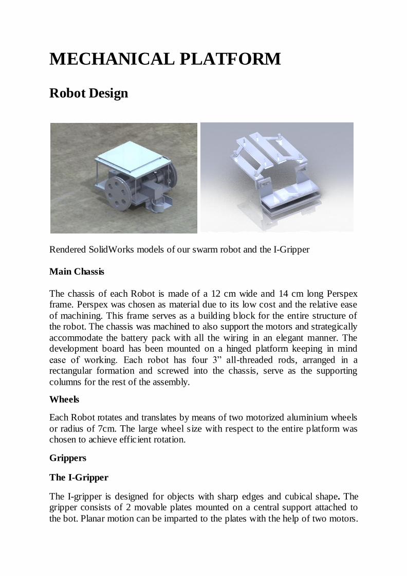
Robot Design
Rendered SolidWorks models of our swarm robot and the I-Gripper
Main Chassis
The chassis of each Robot is made of a 12 cm wide and 14 cm long Perspex frame. Perspex was chosen as material due to its low cost and the relative ease
of machining. This frame serves as a building block for the entire structure of the robot. The chassis was machined to also support the motors and strategically
accommodate the battery pack with all the wiring in an elegant manner. The development board has been mounted on a hinged platform keeping in mind
ease of working. Each robot has four 3” all-threaded rods, arranged in a rectangular formation and screwed into the chassis, serve as the supporting
columns for the rest of the assembly.
Wheels
Each Robot rotates and translates by means of two motorized aluminium wheels
or radius of 7cm. The large wheel size with respect to the entire platform was chosen to achieve efficient rotation.
Grippers
The I-Gripper
The I-gripper is designed for objects with sharp edges and cubical shape. The gripper consists of 2 movable plates mounted on a central support attached to
the bot. Planar motion can be imparted to the plates with the help of two motors.
The distance between the two plates can also be adjusted manually by moving their mounts along the slots inscribed in the central support to configure the
gripper for different sized objects.
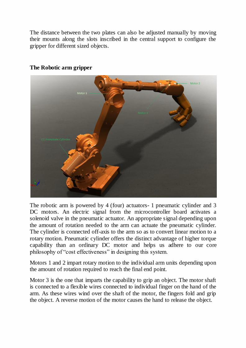
The Robotic arm gripper
The robotic arm is powered by 4 (four) actuators- 1 pneumatic cylinder and 3 DC motors. An electric signal from the microcontroller board activates a solenoid valve in the pneumatic actuator. An appropriate signal depending upon
the amount of rotation needed to the arm can actuate the pneumatic cylinder. The cylinder is connected off-axis to the arm so as to convert linear motion to a
rotary motion. Pneumatic cylinder offers the distinct advantage of higher torque capability than an ordinary DC motor and helps us adhere to our core
philosophy of “cost effectiveness” in designing this system.
Motors 1 and 2 impart rotary motion to the individual arm units depending upon the amount of rotation required to reach the final end point.
Motor 3 is the one that imparts the capability to grip an object. The motor shaft is connected to a flexible wires connected to individual finger on the hand of the
arm. As these wires wind over the shaft of the motor, the fingers fold and grip the object. A reverse motion of the motor causes the hand to release the object.
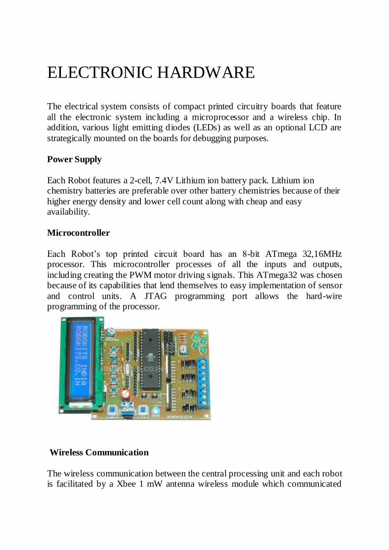
ELECTRONIC HARDWARE
The electrical system consists of compact printed circuitry boards that feature
all the electronic system including a microprocessor and a wireless chip. In addition, various light emitting diodes (LEDs) as well as an optional LCD are
strategically mounted on the boards for debugging purposes.
Power Supply
Each Robot features a 2-cell, 7.4V Lithium ion battery pack. Lithium ion chemistry batteries are preferable over other battery chemistries because of their
higher energy density and lower cell count along with cheap and easy availability.
Microcontroller
Each Robot’s top printed circuit board has an 8-bit ATmega 32,16MHz processor. This microcontroller processes of all the inputs and outputs,
including creating the PWM motor driving signals. This ATmega32 was chosen because of its capabilities that lend themselves to easy implementation of sensor
and control units. A JTAG programming port allows the hard-wire programming of the processor.
Wireless Communication
The wireless communication between the central processing unit and each robot is facilitated by a Xbee 1 mW antenna wireless module which communicated
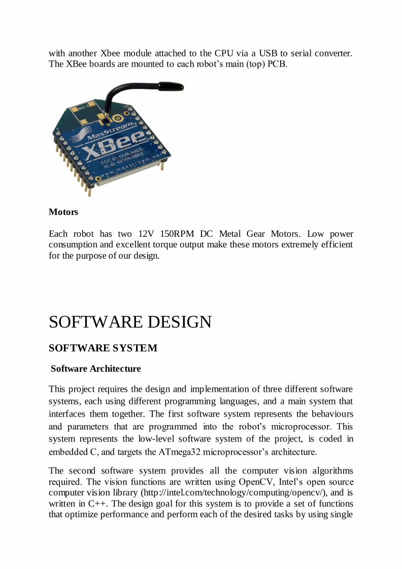
with another Xbee module attached to the CPU via a USB to serial converter. The XBee boards are mounted to each robot’s main (top) PCB.
Motors
Each robot has two 12V 150RPM DC Metal Gear Motors. Low power consumption and excellent torque output make these motors extremely efficient
for the purpose of our design.
SOFTWARE DESIGN
SOFTWARE SYSTEM
Software Architecture
This project requires the design and implementation of three different software
systems, each using different programming languages, and a main system that
interfaces them together. The first software system represents the behaviours
and parameters that are programmed into the robot’s microprocessor. This
system represents the low-level software system of the project, is coded in
embedded C, and targets the ATmega32 microprocessor’s architecture.
The second software system provides all the computer vision algorithms
required. The vision functions are written using OpenCV, Intel’s open source computer vision library (http://intel.com/technology/computing/opencv/), and is
written in C++. The design goal for this system is to provide a set of functions that optimize performance and perform each of the desired tasks by using single
function calls. This complex function intentionally hides the implementation and details of its inner workings.
The final and most crucial software system is the one in charge of integrating all
these systems, and synchronizing them to work together to create and pass messages between them. The final system design goals are to provide a simple
graphical user interface for a complex and well designed object-oriented system. This software system, written in C++, is responsible for handling all the
artificial intelligence commands and behaviours. The project uses and integrates a multi-language platform software system, each one with independent goals,
but targeted to work together. We can refer to the three systems as low-level system (C), midlevel system (C++) and high-level system (again in C++).
Low-Level System (LLS)
The main goal of this system is to give the robots the ability to perform different behaviours to allow interaction with the hardware (i.e., motors, LED’s etc.). The
LLS is designed with the goal of encapsulating each action into simple function calls, each of which will cause one and only one result in hardware. The robot
motion has been segregated into four sub classes: moveforward(), moveleft(), moveright(), stop() and moveback(). The hardware components that need to be
controlled are as follows. • Two Motor Controllers: These motor controllers provide independent
movement to the two wheels. Each wheel receives a high (1) or a low (0) value, corresponding to either an ON or an OFF state of the motor.
• Digital I/0 ports: The ability to set for read or write up to eight distinct pins on the I/O port headers permits additional hardware components to be added to the
system. Some possible uses of these pins are for IR sensors (as inputs) or for LEDs (as outputs). • Serial Communication: The ability to communicate with another serial device
is available. The exchange of data can be used for further intelligent behaviour
In addition to the hardware control provided above, the second goal is to create a wireless protocol to allow the robot to receive and send messages from the
outside world. A function has been created that handles the incoming packet from the wireless receiver and transform its data into one of the commands that
are specified above. By integrating these actions, we can control the behaviour of the robot by simply sending the packets with the right data. In order for this
to work properly, we need to specify a consistent data packet that will tell the robot an appropriate series of actions.
Data Packet Protocol
Each and every robot has a set of four commands:
Move forward: Both Motors A and B are given a command to rotate forwards
Move backward: Both Motors A and B are given a command to rotate
backwards
Move left: The right motor B actuates while Motor A remains passive
Move right: The left motor A actuates while Motor B remains passive.
Stop: No voltage is applied to either motor Each robot has a distinct 1 character code for each of these motions which is
recognized only by the microcontroller of that particular robot. The CPU sends these codes wirelessly through a Xigbee module. They are received by all the
robots but accepted only by that robot whose command subset the code belongs to. In case of a large number of robots, the same set of codes can be used for
each robot along with another code which first identifies the robot. The corresponding robot then receives the signal while other robots wait for their
respective identification commands. For e.g. we used the command subset {W,X,A,D,S} and {T,B,F,H,G} for two robots.
The agent's Xbee wireless module allows the robot to talk to the coordinator
XBee module, which uses the C++ code in the highlevel system. The Xbee modules allow a two-way communication from the sender to a base board plugged into the computer. The importance of wireless communication is
critical since it allows total control of the robot movement and data from an outside computer, which of course can have orders of magnitude of higher
capabilities than the embedded microcontrollers on the robots.
Computer Vision System’s Mid-Level System (MLS)
The main goal of the second software system, the MLS, is to provide multiple
computer vision functions to allow the high-level system to locate and organize all the agents’ information that is located within the area. Enables us to track
each individual robot independently and provides its real time co-ordinates as well its orientation relative to the captured frame.
• Frames are continuously acquired through an overhead 1.3 MP Microsoft Life-cam and transmitted through an USB cable to a computer.
• Once obtained the frame is first subjected to noise reduction techniques and
then the image is broken into the three primary color channels. Subsequently, binary thresholding is done for all the channels to find out the brightest single
expanse of pixels to identify our robot’s top surface using an inbuilt function cvFindContours().
• Using another function cvApproxPoly() , the bright contour is approximated as
a polygon. Depending upon the number of sides and area constraints, the identity of the robot is known. The function cvContourMoments() gives us the
centroid of each contour giving us the real time coordinates of each robot.
• cvFindContours() also provides us with the vertex coordinates, so that the length of each side can be calculated. The shortes t side’s midpoint is found out and hence the direction vector of each robot is calculated.
• To navigate the robot to a particular point the motors are wirelessly sent
commands to rotate the robot until the direction vector and the target vector, calculated using the target point and the robot countour centroid are aligned.
The angle between the vectors is calculated for each frame. Once aligned, the robot is asked to move forward until the contour’s centroid coincides with the
target point. Once it reaches within a given threshold distance of the target point, the robot stops.
High-Level System (HLS)
The high-level system is the most important component of the entire project. The HLS integrates the other two systems and orchestrates their interactions.
Since there will be three agents running at the same time, this compiler runs code in a multithreaded fashion to guarantee the parallel running of the code.
The main design goal for the HLS is to create a heavily object-oriented platform that can be easily expanded while providing robustness, modularity and functionality. The HLS is divided into different subsystems and their
interactions as shown in. The maze navigation and obstacle avoidance algorithms are implemented in the HLS.
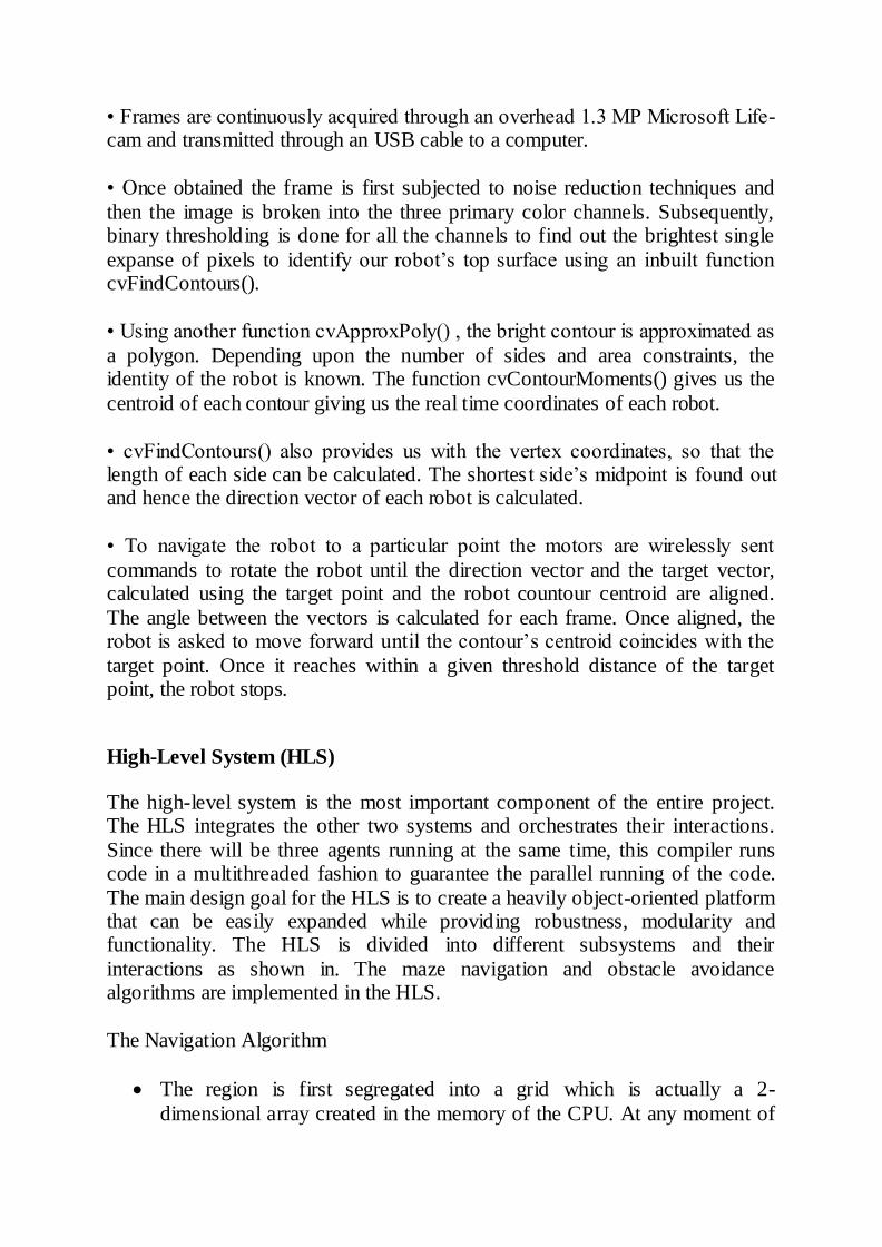
The Navigation Algorithm
The region is first segregated into a grid which is actually a 2-
dimensional array created in the memory of the CPU. At any moment of
time, an element of the array can have three values: 0, 1 or 2. 0 corresponds to an unexplored part of the grid, 1 corresponds to an
explored element of grid and 2 corresponds to a user defined obstacle.
Initially all elements of the array are assigned 0 except the obstacles
which are assigned 2 by the user.
The default motion of the robot is to follow a spiral path for sweep ing the whole grid, i.e. first the outermost elements( 2 rows and 2 columns) of the
grid are explored and then the adjacent elements(again 2 rows and 2 columns) are explored
At any given position of the robot, the next destination of the robot is
found out by the spiral algorithm, and all possible paths are found out to reach the next destination point.
The paths are stored in a separate array in the form of a set of co-ordinates and the shortest path is found out. The robot is then instructed
to follow that path.
Using real time feedback from the overhead camera, the present location
of the robot is tracked and it is guided to the destination point. Once
reached, the next destination point is found out.In this manner, whole of the region is explored while avoiding the obstacles.
The collection algorithm
While navigating through the region, if the onboard sensors of the robot
happen to encounter any sort of trash or waste matter, the motion is temporarily stopped.
The grippers close around the trash matter until the matter is well within the grip. Once secured, the robots abandon their path and the navigation
algorithm stops and move the trash to a common base area whose coordinates are user defined and known prior to the start of the algorithm.
The grippers release the trash matter and the robot retracts back to where
it left the region.
The algorithm is repeated if it finds another trash object until whole of the
allotted region has been scanned.
A typical path followed by a robot
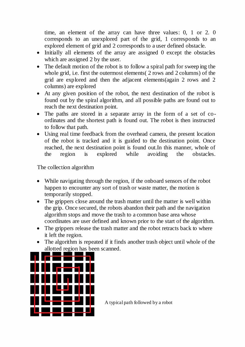
Field Camera Snapshot
Simultaneous detection of three robots (The green segment represents the shortest side of the polygon inscribed on each robot.)
Actual close up of the top view of two robots
SIMULATIONS & TESTING
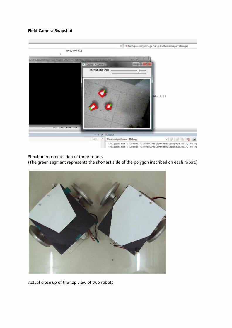
Simulation of the robotic arm gripper
1. The six images showing
the proper orientation of
the arm till the capture
stage sequentially in a
rendered CAD simulation
2. The two images showing
the two modes of the
robotic palm
3. The robotic arm in action
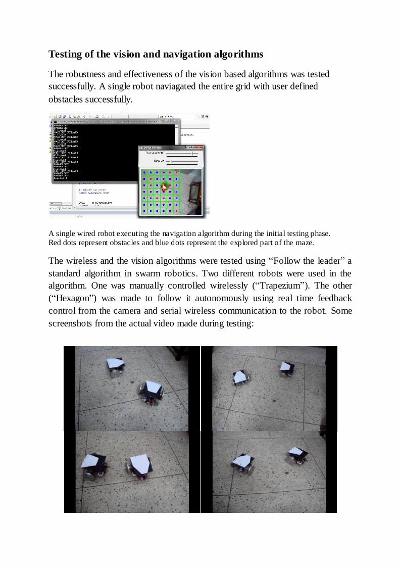
Testing of the vision and navigation algorithms
The robustness and effectiveness of the vision based algorithms was tested
successfully. A single robot naviagated the entire grid with user defined
obstacles successfully.
A single wired robot executing the navigation algorithm during the initial testing phase. Red dots represent obstacles and blue dots represent the explored part of the maze. The wireless and the vision algorithms were tested using “Follow the leader” a
standard algorithm in swarm robotics. Two different robots were used in the
algorithm. One was manually controlled wirelessly (“Trapezium”). The other
(“Hexagon”) was made to follow it autonomously using real time feedback
control from the camera and serial wireless communication to the robot. Some
screenshots from the actual video made during testing:
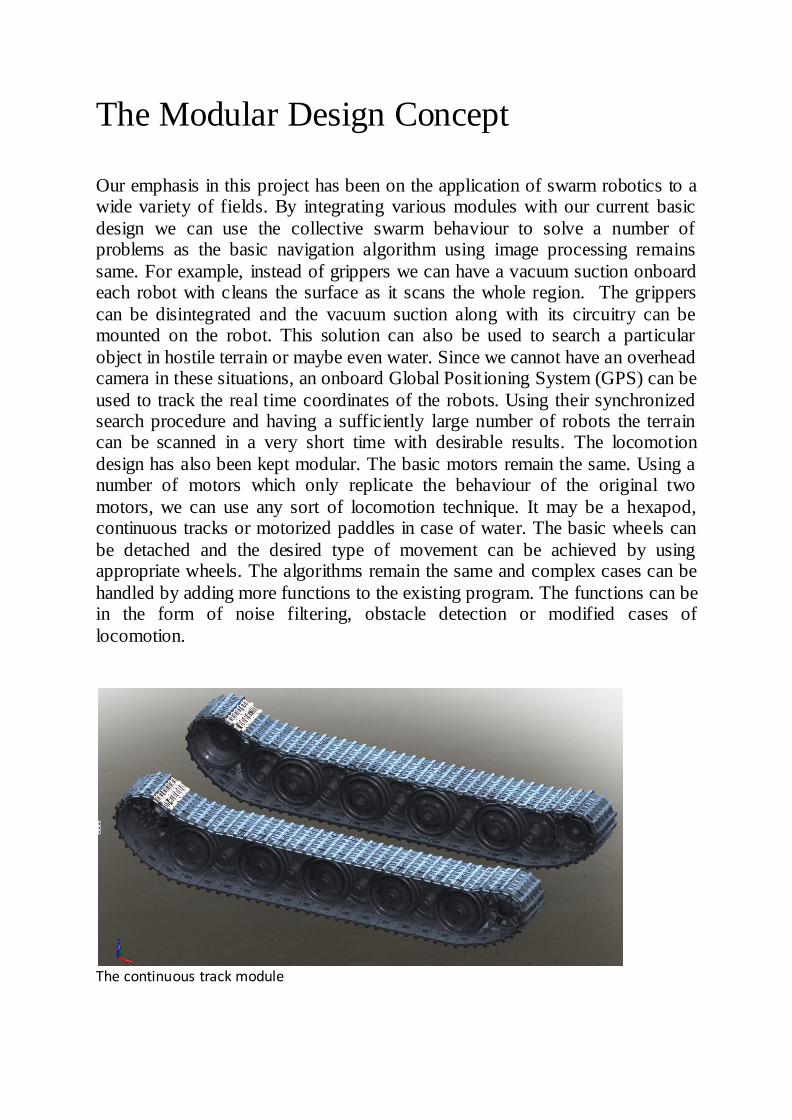
The Modular Design Concept
Our emphasis in this project has been on the application of swarm robotics to a wide variety of fields. By integrating various modules with our current basic
design we can use the collective swarm behaviour to solve a number of problems as the basic navigation algorithm using image processing remains
same. For example, instead of grippers we can have a vacuum suction onboard each robot with cleans the surface as it scans the whole region. The grippers
can be disintegrated and the vacuum suction along with its circuitry can be mounted on the robot. This solution can also be used to search a particular
object in hostile terrain or maybe even water. Since we cannot have an overhead camera in these situations, an onboard Global Positioning System (GPS) can be
used to track the real time coordinates of the robots. Using their synchronized search procedure and having a sufficiently large number of robots the terrain can be scanned in a very short time with desirable results. The locomotion
design has also been kept modular. The basic motors remain the same. Using a number of motors which only replicate the behaviour of the original two
motors, we can use any sort of locomotion technique. It may be a hexapod, continuous tracks or motorized paddles in case of water. The basic wheels can
be detached and the desired type of movement can be achieved by using appropriate wheels. The algorithms remain the same and complex cases can be
handled by adding more functions to the existing program. The functions can be in the form of noise filtering, obstacle detection or modified cases of
locomotion.
The continuous track module
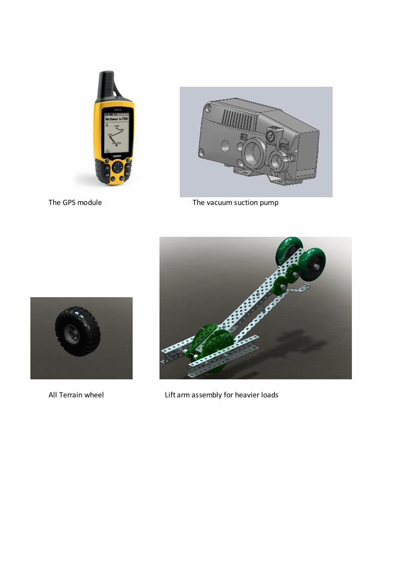
The GPS module The vacuum suction pump
All Terrain wheel Lift arm assembly for heavier loads
Conclusion and Further Endeavour
Multiple agent swarm robotics is the future when it comes to performing daunting tasks efficiently in the least possible time with the minimum resources
possible. The design presented here is a prototype swarm robotics platform capable of performing virtually any kind of application sought of a robot in a much more effective way by approaching the problem in a multi agent
framework, especially keeping in mind the task of collecting randomly scattered garbage over an area.
This particular design offers the d istinct advantage of being cost effective which makes it an affordable choice for the masses. The design brings robotics to an ordinary household. Modular nature of the design offers the advantage of being
used in a wide variety of applications wherein a user can install only the specific set of attachments over the skeleton to meet a particular requirement.
This design has limitless opportunities for work in future. The basic skeleton has been fabricated and rigorously tested. Now, any type of add-on or extension can be developed to meet any specific requirement. The modular design makes
the integration of these add-ons virtually seamless. By changing the design of the skeleton robot from wheeled locomotion to a boat propelled using the same
motors, we can make this design to perform tasks in water bodies.
By integrating adequate extension modules to the basic swarm robot structure, we can achieve very cost effective robotics solutions so flexible that they can
cater to the daily needs of the masses and at the same time are possible of performing sophisticated tasks in the most difficult working areas.