Embed Size (px)
Citation preview
1
Contents LIST OF FIGURES .................................................................................................................................... 3
CHAPTER I ................................................................................................................................................ 4
1.0 ABSTRACT ....................................................................................................................................... 4
1.1 INTRODUCTION ............................................................................................................................. 6
1.2 PROBLEM STATEMENT .............................................................................................................. 7
1.3 OBJECTIVE ..................................................................................................................................... 7
1.4 BENEFITS & CONTRIBUTIONS.................................................................................................. 7
1.5 HYPOTHESIS OF THE PROJECT ............................................................................................... 8
1.6 SCOPE OF RESEARCH ................................................................................................................. 8
1.7 PROJECT OUTLINE ...................................................................................................................... 9
Chapter 1 ............................................................................................................................................. 9
Chapter 2 ............................................................................................................................................. 9
Chapter 3 ............................................................................................................................................. 9
Chapter 4 ............................................................................................................................................. 9
Chapter 5 ............................................................................................................................................. 9
Chapter 6 ............................................................................................................................................. 9
CHAPTER II ............................................................................................................................................. 10
LITERATURE REVIEW .................................................................................................................... 10
2.1 Introduction ....................................................................................................................... 10
2.2.1 Main Integrated Components .......................................................................................... 11
2.2.2 Types of Wind Turbine..................................................................................................... 12
2.2.3 Gear Bearing ..................................................................................................................... 16
2.2.4 Magnetic Flux .................................................................................................................... 19
CHAPTER III ........................................................................................................................................... 21
METHODOLOGY ............................................................................................................................... 21
3.0 Introduction ........................................................................................................................... 21
3.1 Project Flowchart .................................................................................................................. 22
3.2 Process Flowchart ................................................................................................................. 23
3.3 Wind Turbine ........................................................................................................................ 24
3.3 Gear Bearing ......................................................................................................................... 28
3.4 Magnetic Concept ................................................................................................................. 31

2
EXPECTED OUTCOMES ...................................................................................................................... 41
APPENDICES ........................................................................................................................................... 42
REFERENCES .......................................................................................................................................... 43
PUBLISHED JOURNALS ................................................................................................................... 43
SOURCES .......................................................................................................................................... 43
3
LIST OF FIGURES
Figure 1: Darrieus vertical wind turbine with the generator positioned at the base of the tower. The
tower is reinforced with guy wires. ............................................................................................................ 13
Figure 2: Hybrid Darrieus and Savonius self-starting Neoga turbine on top of a building. ........................ 14
Figure 3: Experimental concept for a vertical sail wind machine with a 3 kW rated output. .................... 14
Figure 4: Quiet revolution QR5 wind turbine. ............................................................................................ 15
Figure 5: A direct drive in line electrical generator has auto shut down features and peak power tracking.
It is directly incorporated into the mast. The helical design of the blades ................................................ 15
Figure 6: Dynamics of the harvesting architecture as an interplay of physical phenomena. Arrow
directions indicate causality relations. ....................................................................................................... 20
Figure 7: Gear Bearing Design for The Integration ..................................................................................... 28
Figure 8: Dynamic viscosity vs. shear strain rate. ....................................................................................... 29
Figure 9: Kinematic viscosity vs. shear strain rate. ..................................................................................... 30
Figure 10: coil wrapped around the iron core, placed over a metal plate ................................................. 40
Figure 11: permanent magnet instead of iron core .................................................................................... 40
4
CHAPTER I
1.0 ABSTRACT
Being in 21st century, electricity is one important element in providing a better way of
living to almost every person on earth. However, not everyone or every family is fortunate enough
to get the use of this energy due to several factors such as financial problem and remote location.
In Malaysia, there is still a lack of stable electrical supply especially in rural and isolated areas.
Deep in the forests or in remote islands, there are no proper facilities or technologies that can
properly supply every household with enough electricity for them to go on with their daily lives.
Therefore, an idea to create “one house, one independent power generation system” came
out to help supply enough electrical power to these people living in rural and remote areas without
having to maintain regularly by using free and green energy concepts. This can be achieved by
harvesting wind energy through wind turbine concept, integrated with flux cutting system and gear
bearing system.
The combination of these three concepts (wind turbine system, gear bearing system, and
flux cutting system) shall increase the amount of energy harvested. A wind turbine will be placed
on rooftop of a house to receive wind energy. Regardless of any wind movement, the wind turbine
will rotate in one direction and the wind energy will then transferred to the gear bearing system.
This system is crucial as it will help to control and stabilize the speed of the wind. The generator
that is integrated with flux cutting concept shall generate continuous running of free electrical
energy by which four magnetic poles are placed in most accurate position. The output energy
coming out from the generator will then move to rectifier (to convert AC to DC), before it moves
to bulk boost (to amplify voltage and current). Next, the energy will move to charger (to charge
battery) and then to the battery storage (to store the energy). After that, it will move to inverter (to
convert DC to AC) and to distributor before it is out for household use.

5
There are several advantages can be gained from this idea once it is made into a realization.
It will help provide stable supply of electricity to every household in rural areas for daily activities,
no pollution (the least) produced because it uses only free renewable energy (wind), and it can
reduce household electrical bill in a long run.
This system or idea is ingenious especially in helping low-income community and every
household in rural areas where no stable and enough power supply received. It will help daily
activities to be done efficiently and give more comfortable life to the people. As year 2020 is
approaching soon, this idea certainly will help the nation to achieve the developed country status
and make Malaysia a better country to live in for everyone.
6
1.1 INTRODUCTION
Renewable energy is generally defined as energy that comes from resources which are naturally
replenished on a human timescale, such as sunlight, wind, rain, tides, waves, and geothermal heat.
Renewable energy replaces conventional fuels in four distinct areas: electricity generation, air and
water heating/cooling, motor fuels, and rural (off-grid) energy services.
Based on REN21's 2014 report, renewables contributed 19 percent to our global energy
consumption and 22 percent to our electricity generation in 2012 and 2013, respectively. This
energy consumption is divided as 9% coming from traditional biomass, 4.2% as heat energy (non-
biomass), 3.8% hydroelectricity and 2% is electricity from wind, solar, geothermal, and biomass.
Worldwide investments in renewable technologies amounted to more than US$214 billion in 2013,
with countries like China and the United States heavily investing in wind, hydro, solar and biofuels.
Renewable energy resources exist over wide geographical areas, in contrast to other energy
sources, which are concentrated in a limited number of countries. Rapid deployment of renewable
energy and energy efficiency is resulting in significant energy security, climate change mitigation,
and economic benefits. In international public opinion surveys there is strong support for
promoting renewable sources such as solar power and wind power. At the national level, at least
30 nations around the world already have renewable energy contributing more than 20 percent of
energy supply. National renewable energy markets are projected to continue to grow strongly in
the coming decade and beyond.
While many renewable energy projects are large-scale, renewable technologies are also suited to
rural and remote areas and developing countries, where energy is often crucial in human
development.United Nations' Secretary-General Ban Ki-moon has said that renewable energy has
the ability to lift the poorest nations to new levels of prosperity.
7
1.2 PROBLEM STATEMENT
1. In Malaysia, there is still a lack of stable electrical supply especially in rural areas. Deep
in the forests or in remote islands, there are no proper facilities or technologies that can
properly supply every household with enough electricity for them to go on with their daily
lives.
2. There has yet to be an invention or a device that integrates these 3 main concepts: Wind
Turbine Concept, Gear Bearing Concept & Flux Cutting Concept in harvesting the wind
energy.
1.3 OBJECTIVE
1. To study the possibilities of the integration of the 3 concepts (wind turbine, gear bearing
and flux cutting concept ) used in harvesting wind energy
2. To simulate the integration of the 3 concepts using MATLAB
3. To analyze and run the integration of the 3 concepts
1.4 BENEFITS & CONTRIBUTIONS
1. Impact to Community: Help provide stable supply of electricity to every household in
rural areas for daily activities.
2. Impact to environment: No pollution (the least) because using only free renewable
energy (wind)
3. Impact to economy: Reduce electrical bill in a long run.
8
1.5 HYPOTHESIS OF THE PROJECT
This will meet the objective of this research that is to focus on reducing the real power loss in
the system as well as improving the voltage profile fulfilling’s distribution constraints in the
network distribution. Hypothesis that can be derived is, the lower the power losses in the network
system, the better the voltage profile thus reduce the cost of operating.
1.6 SCOPE OF RESEARCH
This research is created to help supply enough electrical power to the people living in rural and
remote areas. Uses free and green energy concepts. Integrates 3 components (Wind Turbine, Gear
Bearing, Flux Cutting Concepts). No pollution (the least) because using only free renewable
energy (wind). Reduce electrical bill in a long run.
9
1.7 PROJECT OUTLINE
This report is divided into several chapters and is organized as follows:
Chapter 1 reviews about the background of the project in brief. The problem statement, the project
objectives and scope of work of the project are also cover in this chapter.
Chapter 2 describes several types of wind turbines, gear bearings and magnetic flux that are
commonly used nowadays. A few previous researched on harvesting free energy are also discussed
in this chapter.
Chapter 3 describes the fundamental of wind turbines, aerodynamics of wind turbines, gear
bearing and lubricants, viscosity and the magnetic concept. . The overview of past research based
on all proposed method is discussed here. The idea and working principle of the free energy
concept are discussed in this chapter, as well as the mathematical model to implement this
technique.
Chapter 4 presents the methodology of this project. The numerical analysis of network
reconfiguration by implementing proposed algorithm using MATLAB software has been
discussed in this chapter.
Chapter 5 presents the result obtained when the proposed research is executed to three different
structure of distribution system (wind turbine, gear bearing and magnetic flux) and compared from
each other. The analysis of the result and discussion are provided in this chapter.
Chapter 6 presents the overall conclusions of the project and possible future development for this
project.
10
CHAPTER II
LITERATURE REVIEW
OVERVIEW OF HARVESTING WIND ENERGY THROUGH WIND TURBINE
CONCEPT, INTEGRATED WITH FREE ENERGY FLUX CUTTING SYSTEM AND
GEAR BEARING SYSTEM
2.1 Introduction
This system or idea is ingenious especially in helping low-income community and every household
in rural areas where no stable and enough power supply received. It will help daily activities to be
done efficiently and give more comfortable life to the people. As year 2020 is approaching soon,
this idea certainly will help the nation to achieve the developed country status and make Malaysia
a better country to live in for everyone.
11
2.2.1 Main Integrated Components
There are many ways and methods in harvesting free energy. In this research, three
main components has been selected in order to harvest the energy efficiently. The
selected methods and components are based on the geographical area where this project
will be implemented. The selection of each components has been decided after
shortlisting each components and comparing it with the same component but with
different designs. Based on the comparison, the efficiency of each components that
offers more output and result shall be selected and implemented for this research. The
main components are as listed below:
a) Wind Turbine
b) Gear Bearing
c) Magnetic Flux
12
2.2.2 Types of Wind Turbine
Vertical axis wind turbines are advocated as being capable of catching the wind from
all directions, and do not need yaw mechanisms, rudders or downwind coning. Their
electrical generators can be positioned close to the ground, and hence easily accessible.
A disadvantage is that some designs are not self-starting.
There have been two distinct types of vertical axis wind turbines: The Darrieus and the
Savonius types. The Darrieus rotor was researched and developed extensively by
Sandia National Laboratories in the USA in the 1980's.
New concepts of vertical axis wind machines are being introduced such as the helical
types particularly for use in urban environments where they would be considered safer
due to their lower rotational speeds avoiding the risk of blade ejection and since they
can catch the wind from all directions.
Horizontal axis wind turbines are typically more efficient at converting wind energy
into electricity than vertical axis wind turbines. For this reason they have become
dominant in the commercial utility-scale wind power market. However, small vertical
axis wind turbines are more suited to urban areas as they have a low noise level and
because of the reduced risk associated with their slower rates of rotation.
One can foresee some future where each human dwelling in the world is equipped with
wind generators and solar collectors, as global peak petroleum is reached making them
indispensable for human well-being. They are well suited for green buildings
architectural projects as well as futuristic aquaponics; where vertical farming in a
skyscraper uses automated farming technologies converting urban sewage into
agricultural products. Their cost will come down appreciably once they are mass
produced on a production line scale equivalent to the automobile industry.
The economic development and viable use of horizontal axis wind turbines would, in
the future be limited, partly due to the high stress loads on the large blades. It is
recognized that, although less efficient, vertical axis wind turbines do not suffer so
much from the constantly varying gravitational loads that limit the size of horizontal
axis turbines.
13
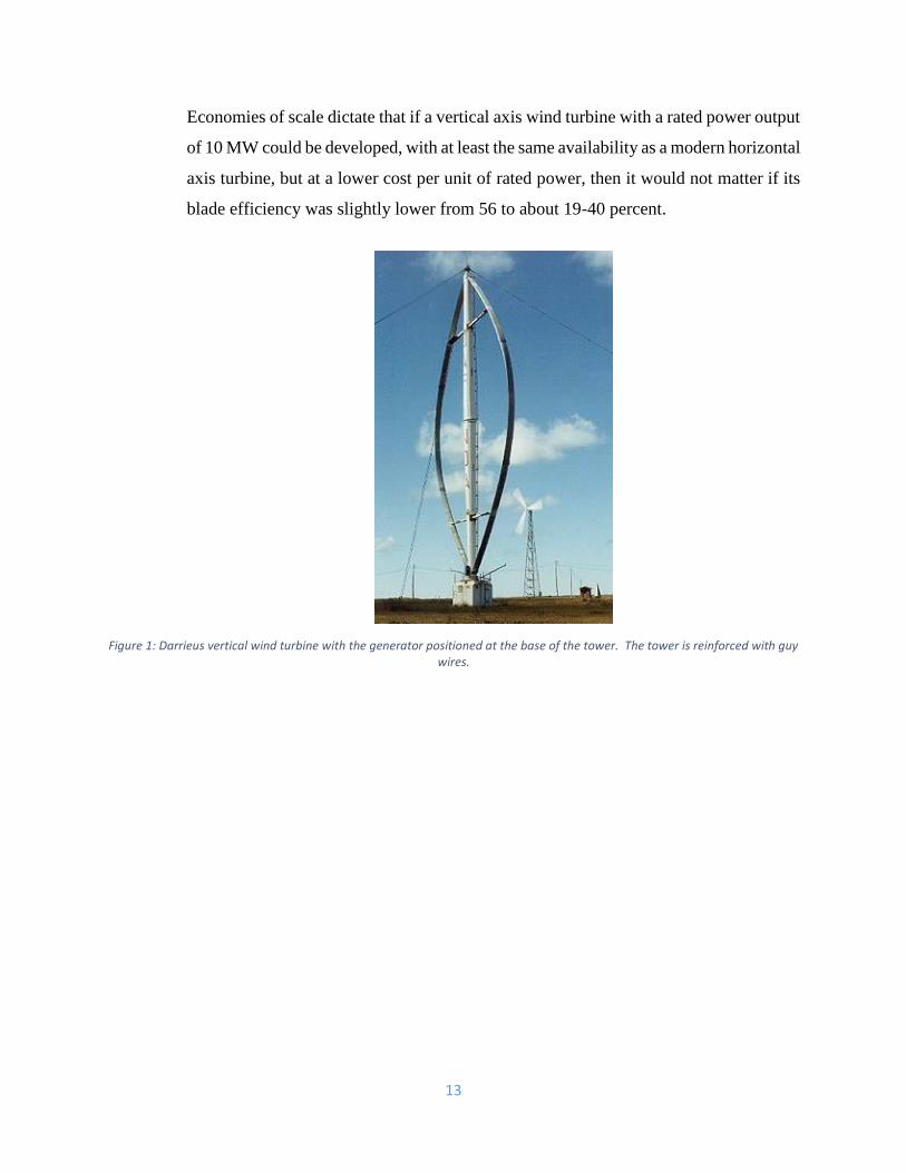
Economies of scale dictate that if a vertical axis wind turbine with a rated power output
of 10 MW could be developed, with at least the same availability as a modern horizontal
axis turbine, but at a lower cost per unit of rated power, then it would not matter if its
blade efficiency was slightly lower from 56 to about 19-40 percent.
Figure 1: Darrieus vertical wind turbine with the generator positioned at the base of the tower. The tower is reinforced with guy wires.
14
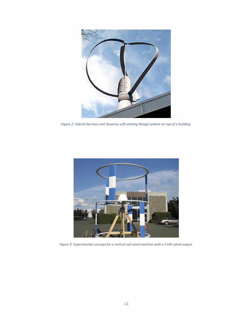
Figure 2: Hybrid Darrieus and Savonius self-starting Neoga turbine on top of a building.
Figure 3: Experimental concept for a vertical sail wind machine with a 3 kW rated output.
15
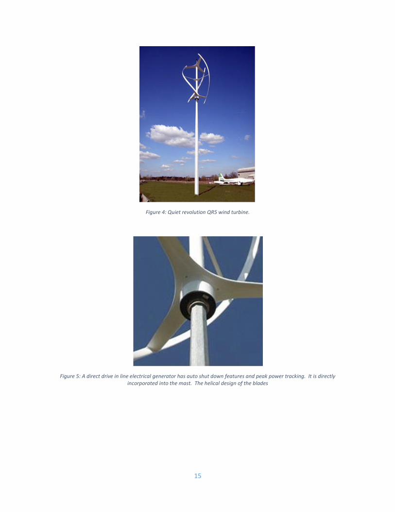
Figure 4: Quiet revolution QR5 wind turbine.
Figure 5: A direct drive in line electrical generator has auto shut down features and peak power tracking. It is directly incorporated into the mast. The helical design of the blades
16
2.2.3 Gear Bearing
As proven source of clean and affordable energy, wind resources clearly have a vital
role to play in energetic sustainability. In this sense it is necessary to have wind turbines
that maximize the use of eolic energy and achieve their design life goals with minimal
maintenance.
Gearboxes have plagued the wind power industry. Wind turbine failures can be
extremely costly in terms of repair costs, replacement parts and lost power, and the
gearbox is the most likely component to have a major effect on the turbine availability.
Since the establishment of the wind energy industry large failure rates of the gearboxes
have been observed. Windmills, often placed in hostile environments, have premature
bearing and gear failures, and the performance of the gear oils used for their lubrication
also have an important role in gearbox reliability. Most wind turbine gearbox failures
are rooted to the bearings.
Due to economic and environmental constraints it is mandatory to increase the
efficiency of windmills, to reach the highest efficiency of planetary gear drives and
their parts (gears, rolling bearings, seals, etc.) and to minimize the heat generation in
the gearboxes. In order to increase gearbox efficiency it is important identify the main
sources of power loss. The most common wind turbine gearboxes have planetary gears
and the main losses occurring are: friction loss between the meshing teeth and friction
loss in the bearings and friction loss in the seals, lubricant churning losses and energy
loss due to air-drag.
Friction generated between the meshing teeth is the main source of power loss in a
planetary gear. On the other hand, rolling bearing friction is also very important
because it can reach about 30% of total power loss occurring within the mechanism. In
this sense, understand the friction torque generated within rolling bearings is essential
in order to reduce their contribution to the overall power loss. There are four physical
friction sources inside a rolling bearing: rolling friction, sliding friction, seal friction
and drag losses. The most important ones in the case of windmill applications (high
torque and low speed) are the friction occurring in the contact between the rolling
elements and raceways (sliding friction) and the friction due to the lubricant flow
17
between the bearing elements (rolling friction). These energy loss mechanisms are
highly dependent on the lubricant ability to generate an effective oil film between the
rolling elements and the raceways and on the physical properties of the gear oils.
Wind turbine gearboxes are composed of various mechanical parts, including different
types of rolling bearings. In this sense we intend to identify the loss mechanisms
occurring in rolling bearings lubricated with wind turbine gear oils. For that purpose
the friction torque losses in cylindrical roller thrust bearings (81107) were identified
and compared when different lubricants are used. Five different fully formulated gear
oils were characterized and tested on a cylindrical roller thrust bearing (81107)
submitted to an axial load of 7000 N and rotational speeds between 150 and 1500 rpm.
The tests were performed on a modified four-ball machine (Cameron-Plint TE 82/7752)
using a special assembly for the thrust roller bearings (81107).
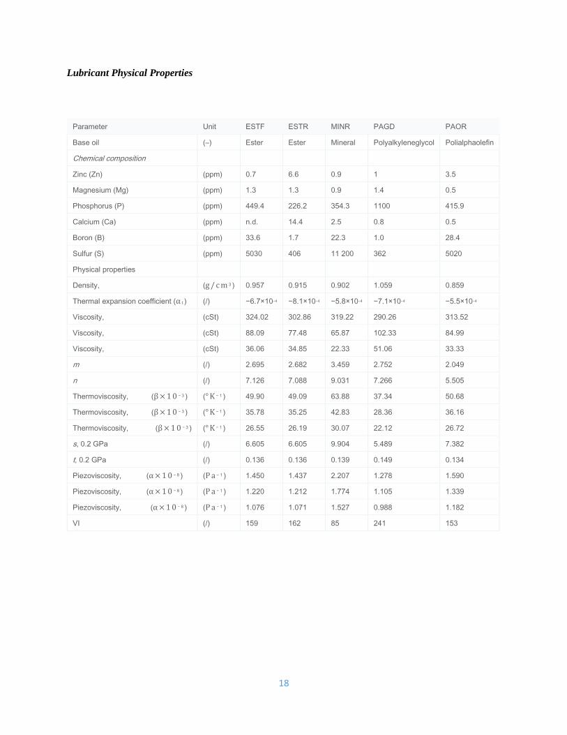
All the lubricants tested are fully formulated gear oils have a viscosity grade ISO VG
320 and may be used in the lubrication of wind turbine gearboxes. This is a comparative
study of different base oils: ester (ESTF and ESTR), mineral (MINR),
polyalkyleneglycol (PAGD) and polyalphaolefin (PAOR). Table 1 displays the
physical properties of the five lubricants as well as their chemical composition.
18
Lubricant Physical Properties
Parameter Unit ESTF ESTR MINR PAGD PAOR
Base oil (–) Ester Ester Mineral Polyalkyleneglycol Polialphaolefin
Chemical composition
Zinc (Zn) (ppm) 0.7 6.6 0.9 1 3.5
Magnesium (Mg) (ppm) 1.3 1.3 0.9 1.4 0.5
Phosphorus (P) (ppm) 449.4 226.2 354.3 1100 415.9
Calcium (Ca) (ppm) n.d. 14.4 2.5 0.8 0.5
Boron (B) (ppm) 33.6 1.7 22.3 1.0 28.4
Sulfur (S) (ppm) 5030 406 11 200 362 5020
Physical properties
Density, (g/cm 3 ) 0.957 0.915 0.902 1.059 0.859
Thermal expansion coefficient (α t ) (/) −6.7×10⁻⁴ −8.1×10⁻⁴ −5.8×10⁻⁴ −7.1×10⁻⁴ −5.5×10⁻⁴
Viscosity, (cSt) 324.02 302.86 319.22 290.26 313.52
Viscosity, (cSt) 88.09 77.48 65.87 102.33 84.99
Viscosity, (cSt) 36.06 34.85 22.33 51.06 33.33
m (/) 2.695 2.682 3.459 2.752 2.049
n (/) 7.126 7.088 9.031 7.266 5.505
Thermoviscosity, (β×10 − 3 ) (°K − 1 ) 49.90 49.09 63.88 37.34 50.68
Thermoviscosity, (β×10 − 3 ) (°K − 1 ) 35.78 35.25 42.83 28.36 36.16
Thermoviscosity, (β×10 − 3 ) (°K − 1 ) 26.55 26.19 30.07 22.12 26.72
s, 0.2 GPa (/) 6.605 6.605 9.904 5.489 7.382
t, 0.2 GPa (/) 0.136 0.136 0.139 0.149 0.134
Piezoviscosity, (α×10 − 8 ) (Pa − 1 ) 1.450 1.437 2.207 1.278 1.590
Piezoviscosity, (α×10 − 8 ) (Pa − 1 ) 1.220 1.212 1.774 1.105 1.339
Piezoviscosity, (α×10 − 8 ) (Pa − 1 ) 1.076 1.071 1.527 0.988 1.182
VI (/) 159 162 85 241 153
19
2.2.4 Magnetic Flux
The field of energy harvesting has been actively researched for many decades,
exploring the different physical phenomena that can be harnessed in order to generate
useful electrical energy out of wasted ambient or residual energy sources, such as
ambient or machine vibrations, dissipated heat, etc. Such physical phenomena include,
for example, the photoelectric effect, piezoelectricity, magnetic induction and
thermoelectricity. The harvesting architectures found in the literature of the field are
manifold, and strongly depend on the physical mechanism by which the harvested
energy is transduced into electricity. The usual methods of analyzing such physical
mechanisms are FEA simulations and linear parametric models, such as ANSYS
simulations of an electromagnetic micro-power generator, COMSOL simulations of a
self-powered thermal sensor, and linear models for several harvesting architectures. In
the case of electromagnetic architectures, even though Maxwell’s equations are linear
in the fields, the geometry of most of these architectures imposes boundary conditions
that render the solutions nonlinear. This has the following implications: -
20
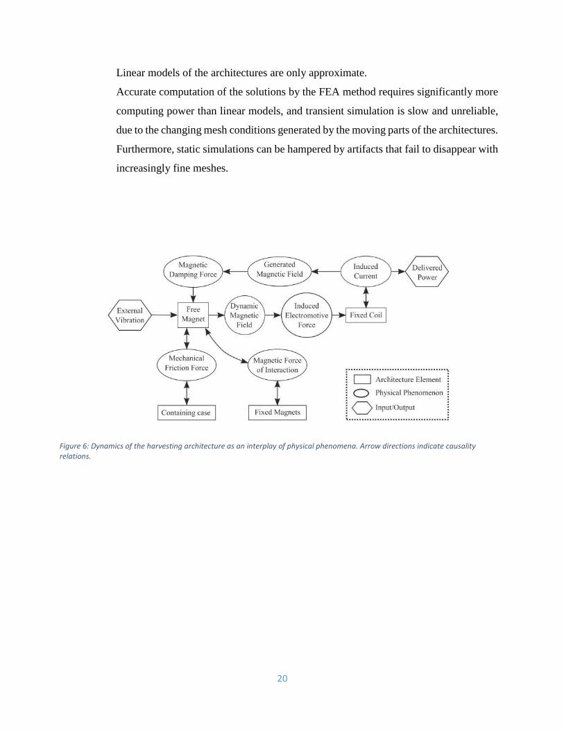
Figure 6: Dynamics of the harvesting architecture as an interplay of physical phenomena. Arrow directions indicate causality relations.
Linear models of the architectures are only approximate.
Accurate computation of the solutions by the FEA method requires significantly more
computing power than linear models, and transient simulation is slow and unreliable,
due to the changing mesh conditions generated by the moving parts of the architectures.
Furthermore, static simulations can be hampered by artifacts that fail to disappear with
increasingly fine meshes.
21
CHAPTER III
METHODOLOGY
3.0 Introduction
The combination of these three concepts (wind turbine system, gear bearing system,
and flux cutting system) shall increase the amount of energy harvested. A wind turbine
will be placed on rooftop of a house to receive wind energy. Regardless of wind
movement, the wind turbine will rotate in one direction and the wind energy will then
transferred to the gear bearing system. This system is crucial as it will help control and
stabilize the speed of the wind. The turbine will also be integrated with generator that
uses flux cutting concept that shall generate continuous running of free electrical
energy by which four magnetic poles are placed in most accurate position. The output
energy coming out from the generator will then move to rectifier (to convert AC to
DC), to bulk boost (to amplify voltage and current), to charger (to charge battery)
before to battery storage (to store the energy), to inverter (to convert DC to AC) and to
distributor before it is out for household use.
22
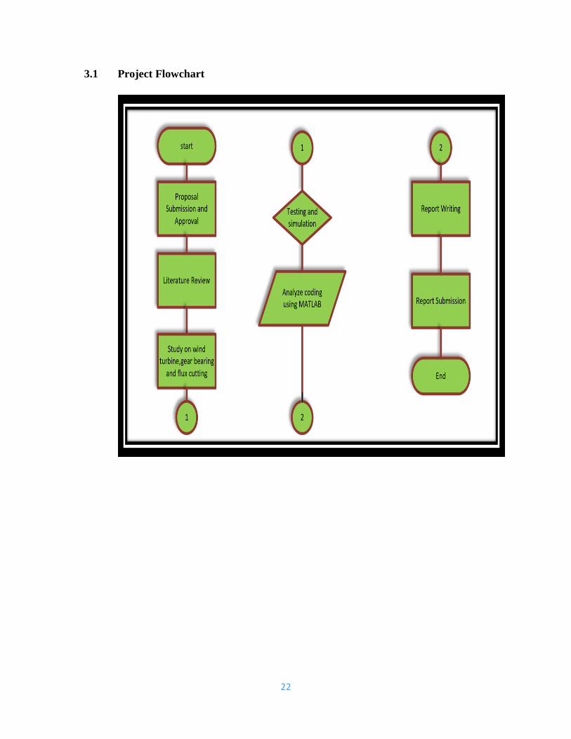
3.1 Project Flowchart
23
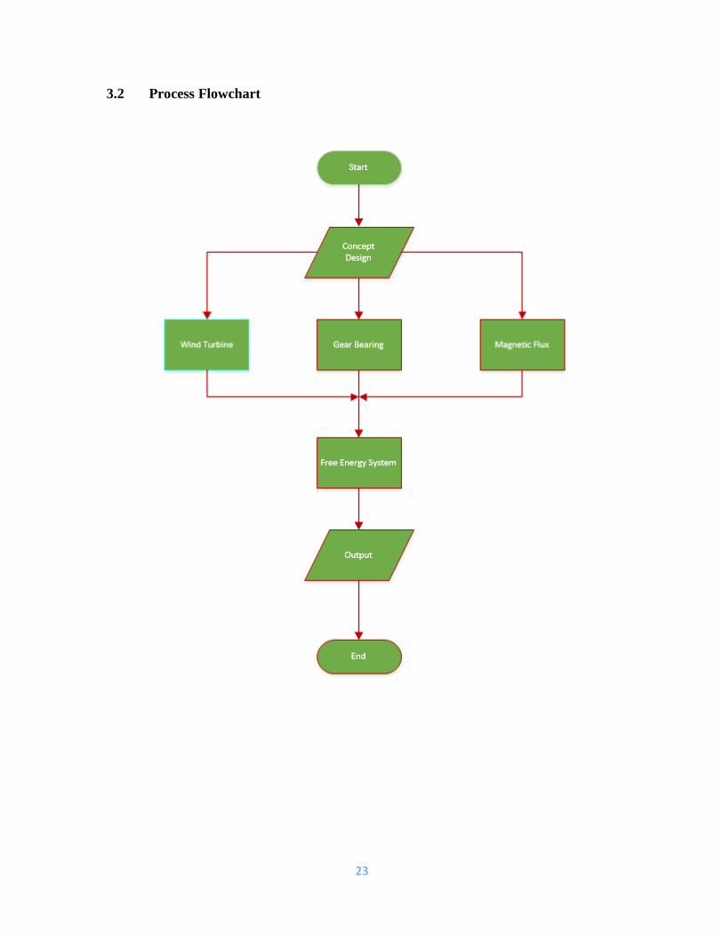
3.2 Process Flowchart
24
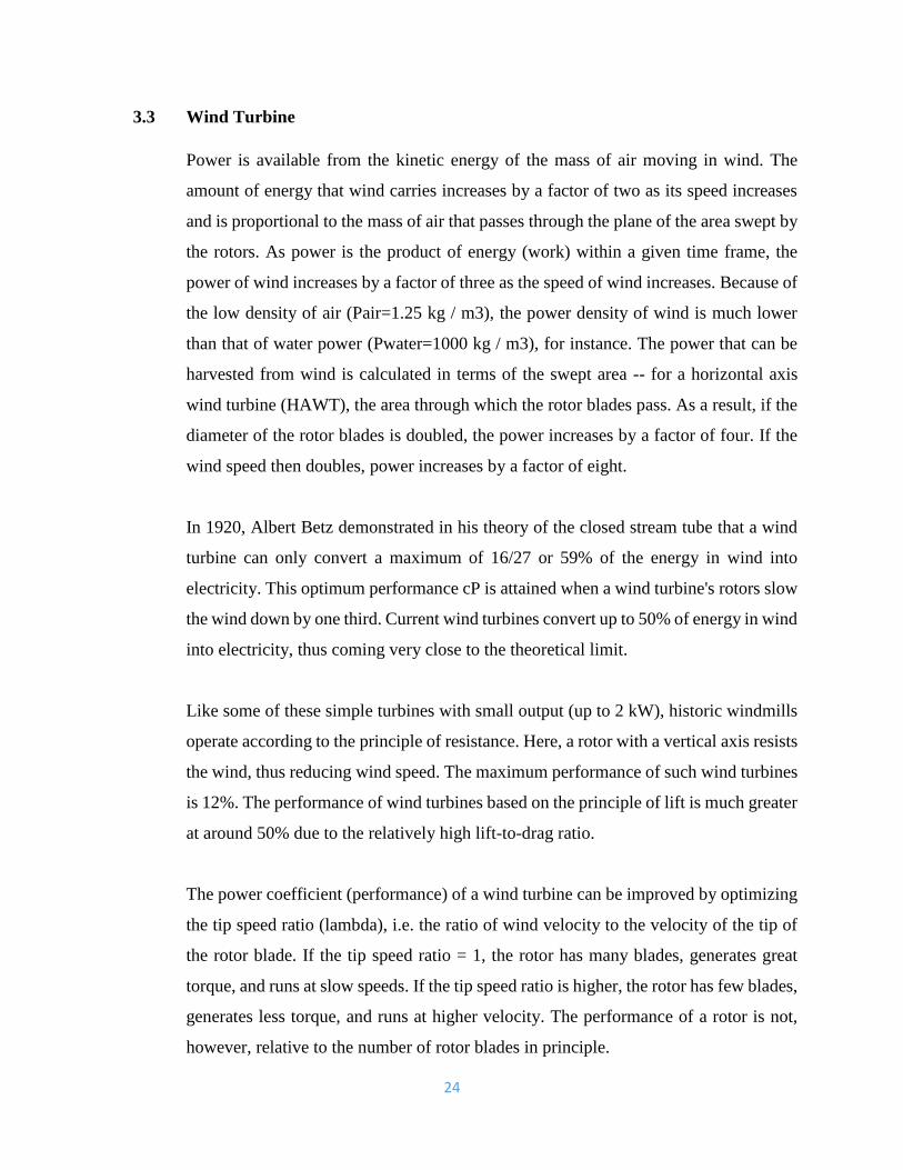
3.3 Wind Turbine
Power is available from the kinetic energy of the mass of air moving in wind. The
amount of energy that wind carries increases by a factor of two as its speed increases
and is proportional to the mass of air that passes through the plane of the area swept by
the rotors. As power is the product of energy (work) within a given time frame, the
power of wind increases by a factor of three as the speed of wind increases. Because of
the low density of air (Pair=1.25 kg / m3), the power density of wind is much lower
than that of water power (Pwater=1000 kg / m3), for instance. The power that can be
harvested from wind is calculated in terms of the swept area -- for a horizontal axis
wind turbine (HAWT), the area through which the rotor blades pass. As a result, if the
diameter of the rotor blades is doubled, the power increases by a factor of four. If the
wind speed then doubles, power increases by a factor of eight.
In 1920, Albert Betz demonstrated in his theory of the closed stream tube that a wind
turbine can only convert a maximum of 16/27 or 59% of the energy in wind into
electricity. This optimum performance cP is attained when a wind turbine's rotors slow
the wind down by one third. Current wind turbines convert up to 50% of energy in wind
into electricity, thus coming very close to the theoretical limit.
Like some of these simple turbines with small output (up to 2 kW), historic windmills
operate according to the principle of resistance. Here, a rotor with a vertical axis resists
the wind, thus reducing wind speed. The maximum performance of such wind turbines
is 12%. The performance of wind turbines based on the principle of lift is much greater
at around 50% due to the relatively high lift-to-drag ratio.
The power coefficient (performance) of a wind turbine can be improved by optimizing
the tip speed ratio (lambda), i.e. the ratio of wind velocity to the velocity of the tip of
the rotor blade. If the tip speed ratio = 1, the rotor has many blades, generates great
torque, and runs at slow speeds. If the tip speed ratio is higher, the rotor has few blades,
generates less torque, and runs at higher velocity. The performance of a rotor is not,
however, relative to the number of rotor blades in principle.
25
3.3.1 The Aerodynamics of Wind Turbine
The power coefficient of a wind turbine's rotor blade is calculated according to the laws
of airfoil theory. As with the wing of an airplane, air passing over a rotor blade creates
an aerodynamic profile with low pressure above the wing, pulling the wing up, and
overpressure below, pushing it up.
The difference in pressures exerts a lift on the wing vertical to the direction in which
the wind is blowing and creates resistance in the direction of the wind (incident flow).
For a wind turbine's rotor blade rotating around the rotor axis, the incident flow is the
result of the geometric addition of wind velocity v and the circumferential speed u,
which increases in linear fashion the longer the blade is. In other words, the lift exerted
on the rotor blade is not only the result of wind velocity, but mostly out of the blade's
own rotation. Speeds at the tip of the blade are thus very great. Current wind turbines
have rotor tips travelling at velocities six times faster than the speed of the wind. The
tip speed ratio is thus lambda = 6. The rotor tip can then be traveling at velocities of 60
m/s to 80 m/s.
The energy that the rotor harvests is equivalent to the lifting force in the swept area
minus the resistance force in the swept area. The forces applied in the direction of the
axis drive the rotor, which then not only harvests the energy of the wind, but also exerts
a load on the tower and the foundation.
The Betz Theory allows us to calculate the optimal geometry of a rotor blade (thickness
of blade and blade twisting).
26
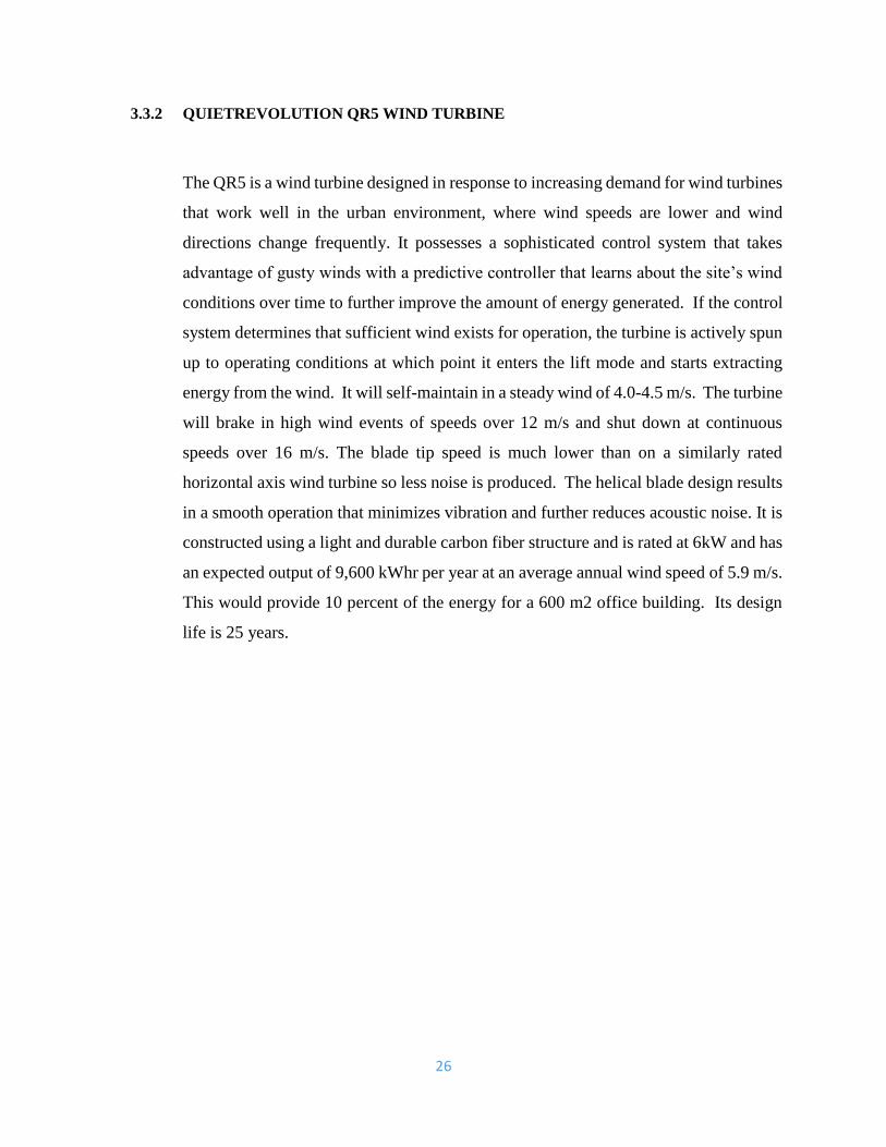
3.3.2 QUIETREVOLUTION QR5 WIND TURBINE
The QR5 is a wind turbine designed in response to increasing demand for wind turbines
that work well in the urban environment, where wind speeds are lower and wind
directions change frequently. It possesses a sophisticated control system that takes
advantage of gusty winds with a predictive controller that learns about the site’s wind
conditions over time to further improve the amount of energy generated. If the control
system determines that sufficient wind exists for operation, the turbine is actively spun
up to operating conditions at which point it enters the lift mode and starts extracting
energy from the wind. It will self-maintain in a steady wind of 4.0-4.5 m/s. The turbine
will brake in high wind events of speeds over 12 m/s and shut down at continuous
speeds over 16 m/s. The blade tip speed is much lower than on a similarly rated
horizontal axis wind turbine so less noise is produced. The helical blade design results
in a smooth operation that minimizes vibration and further reduces acoustic noise. It is
constructed using a light and durable carbon fiber structure and is rated at 6kW and has
an expected output of 9,600 kWhr per year at an average annual wind speed of 5.9 m/s.
This would provide 10 percent of the energy for a 600 m2 office building. Its design
life is 25 years.
27
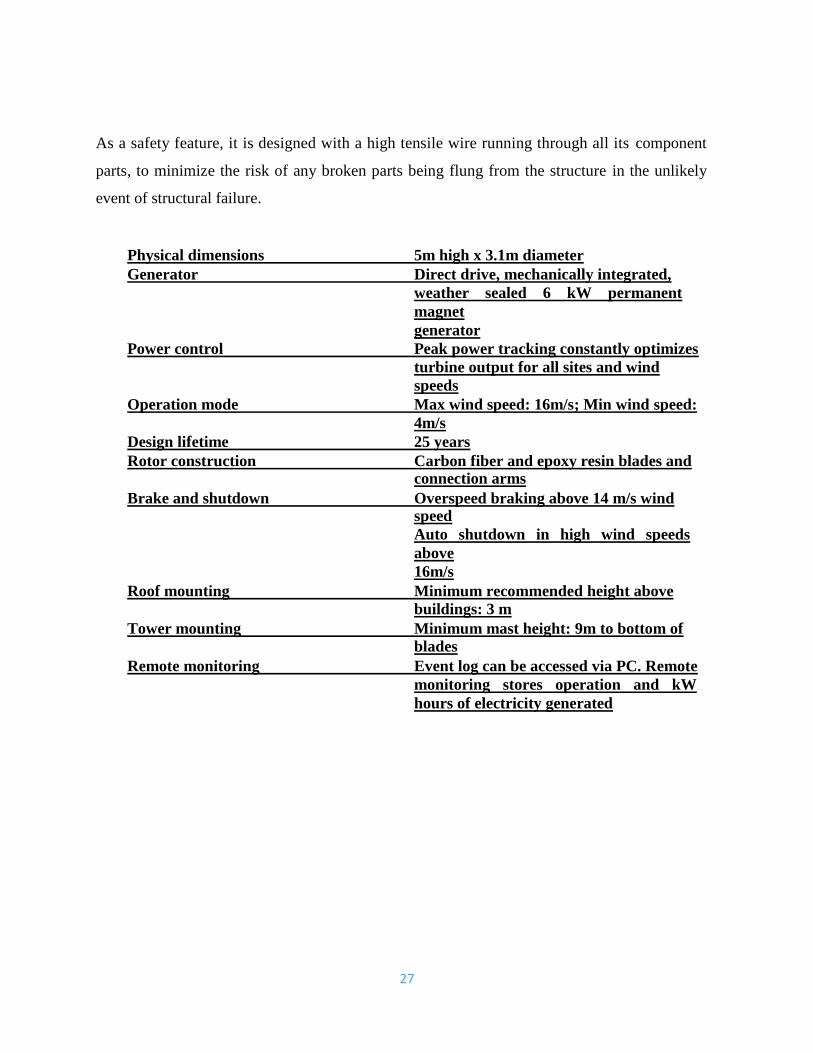
As a safety feature, it is designed with a high tensile wire running through all its component
parts, to minimize the risk of any broken parts being flung from the structure in the unlikely
event of structural failure.
Physical dimensions 5m high x 3.1m diameter
Generator Direct drive, mechanically integrated,
weather sealed 6 kW permanent
magnet
generator
Power control Peak power tracking constantly optimizes
turbine output for all sites and wind
speeds
Operation mode Max wind speed: 16m/s; Min wind speed:
4m/s
Design lifetime 25 years
Rotor construction Carbon fiber and epoxy resin blades and connection arms
Brake and shutdown Overspeed braking above 14 m/s wind speed
Auto shutdown in high wind speeds
above
16m/s
Roof mounting Minimum recommended height above
buildings: 3 m
Tower mounting Minimum mast height: 9m to bottom of
blades
Remote monitoring Event log can be accessed via PC. Remote
monitoring stores operation and kW
hours of electricity generated
28
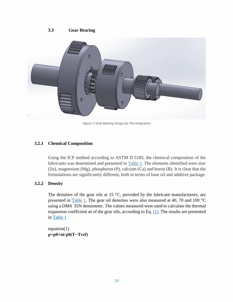
3.3 Gear Bearing
3.2.1 Chemical Composition
Using the ICP method according to ASTM D 5185, the chemical composition of the
lubricants was determined and presented in Table 1. The elements identified were zinc
(Zn), magnesium (Mg), phosphorus (P), calcium (Ca) and boron (B). It is clear that the
formulations are significantly different, both in terms of base oil and additive package.
3.2.2 Density
The densities of the gear oils at 15 °C, provided by the lubricant manufacturers, are
presented in Table 1. The gear oil densities were also measured at 40, 70 and 100 °C
using a DMA 35N densimeter. The values measured were used to calculate the thermal
expansion coefficient αt of the gear oils, according to Eq. (1). The results are presented
in Table 1
equation(1)
ρ=ρ0+αt⋅ρ0(T−Tref)
Figure 7: Gear Bearing Design for The Integration
29
3.2.3 Kinematic Viscosity
The kinematic viscosities of each oil were measured using an Engler viscometer. The
measurements were performed at 40, 70 and 100 °C according to ASTM D341 and are
displayed in Table 1. At 40 °C all the kinematic viscosities were very similar, since all the gear
oils had the same viscosity grade. However, at 100 °C the kinematic viscosities were
significantly different: 22.3 cSt for the MINR oil, 51.6 cSt for the PAGD and 33.3, 34.9 and 36.6
for the PAOR, ESTR and ESTF, respectively.
The kinematic viscosities were used to determine the Viscosity Index of each lubricant. The
MINR gear oil had the lowest VI (85) while the PAGD oil had the highest value (241). The PAOR,
ESTR, ESTF gear oils had intermediate values, respectively, 153, 162 and 159.
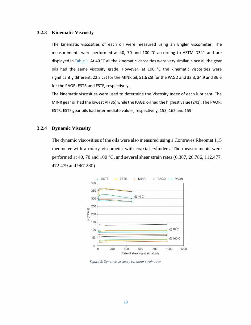
3.2.4 Dynamic Viscosity
The dynamic viscosities of the oils were also measured using a Contraves Rheomat 115
rheometer with a rotary viscometer with coaxial cylinders. The measurements were
performed at 40, 70 and 100 °C, and several shear strain rates (6.387, 26.786, 112.477,
472.479 and 967.280).
Figure 8: Dynamic viscosity vs. shear strain rate.
30
At 40 °C the dynamic viscosity was not independent of the shear strain rate,
indicating that the lubricant behavior was non-Newtonian. At higher temperatures
(70 and 100 °C) such non-Newtonian behavior was no longer observed and the
dynamic viscosity was constant whatever the shear strain rate. This behavior was
observed for all the gear oils.
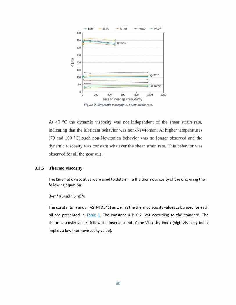
3.2.5 Thermo viscosity
The kinematic viscosities were used to determine the thermoviscosity of the oils, using the
following equation:
β=m/T(υ+a)ln(υ+a)/υ
The constants m and n (ASTM D341) as well as the thermoviscosity values calculated for each
oil are presented in Table 1. The constant a is 0.7 cSt according to the standard. The
thermoviscosity values follow the inverse trend of the Viscosity Index (high Viscosity Index
implies a low thermoviscosity value).
Figure 9: Kinematic viscosity vs. shear strain rate.
31
3.4 Magnetic Concept
Magnetism, along with electricity, belongs to a larger phenomenon, electromagnetism,
or the force generated by the passage of an electric current through matter. When two
electric charges are at rest, it appears to the observer that the force between them is
merely electric. If the charges are in motion, however—and in this instance motion or
rest is understood in relation to the observer—then it appears as though a different sort
of force, known as magnetism, exists between them.
In fact, the difference between magnetism and electricity is purely artificial. Both are
manifestations of a single fundamental force, with "magnetism" simply being an
abstraction that people use for the changes in electromagnetic force created by the
motion of electric charges. It is a distinction on the order of that between water and
wetness; nonetheless, it is often useful and convenient to discuss the two phenomena
as though they were separate.
At the atomic level, magnetism is the result of motion by electrons, negatively charged
subatomic particles, relative to one another. Rather like planets in a solar system,
electrons both revolve around the atom's nucleus and rotate on their own axes. (In fact
the exact nature of their movement is much more complex, but this analogy is accurate
enough for the present purposes.) Both types of movement create a magnetic force field
between electrons, and as a result the electron takes on the properties of a tiny bar
magnet with a North Pole and South Pole. Surrounding this infinitesimal magnet are
lines of magnetic force, which begin at the North Pole and curve outward, describing
an ellipse as they return to the South Pole.
32
In most atomic elements, the structure of the atom is such that the electrons align in a
random manner, rather like a bunch of basketballs bumping into one another as they
float in a swimming pool. Because of this random alignment, the small magnetic fields
cancel out one another. Two such self-canceling particles are referred to as paired
electrons, and again, the analogy to bar magnets is an appropriate one: if one were to
shake a bag containing an even number of bar magnets, they would all wind up in pairs,
joined at opposing (north-south) poles.
There are, however, a very few elements in which the fields line up to create what is
known as a net magnetic dipole, or a unity of direction—rather like a bunch of
basketballs simultaneously thrown from in the same direction at the same time. These
elements, among them iron, cobalt, and nickel, as well as various alloys or mixtures,
are commonly known as magnetic metals or natural magnets.
It should be noted that in magnetic metals, magnetism comes purely from the alignment
of forces exerted by electrons as they spin on their axes, whereas the forces created by
their orbital motion around the nucleus tend to cancel one another out. But in magnetic
rare earth elements such as cerium, magnetism comes both from rotational and orbital
forms of motion. Of principal concern in this discussion, however, is the behavior of
natural magnets on the one hand, and of nonmagnetic materials on the other.
There are five different types of magnetism—diamagnetism, paramagnetism,
ferromagnetism, ferrimagnetism, and antiferromagnetism. Actually, these terms
describe five different types of response to the process of magnetization, which occurs
when an object is placed in a magnetic field.
A magnetic field is an area in which a magnetic force acts on a moving charged particle
such that the particle would experience no force if it moved in the direction of the
magnetic field—in other words, it would be "drawn," as a ten-penny nail is drawn to a
common bar or horseshoe (U-shaped) magnet. An electric current is an example of a
moving charge, and indeed one of the best ways to create a magnetic field is with a
current. Often this is done by means of a solenoid, a current-carrying wire coil through
which the material to be magnetized is passed, much as one would pass an object
through the interior of a spring.
33
All materials respond to a magnetic field; they just respond in different ways. Some
non-magnetic substances, when placed within a magnetic field, slightly reduce the
strength of that field, a phenomenon known as diamagnetism. On the other hand, there
are nonmagnetic substances possessing an uneven number of electrons per atom, and
in these instances a slight increase in magnetism, known as paramagnetism, occurs.
Paramagnetism always has to overcome diamagnetism, however, and hence the gain in
magnetic force is very small. In addition, the thermal motion of atoms and molecules
prevents the objects' magnetic fields from coming into alignment with the external
field. Lower temperatures, on the other hand, enhance the process of paramagnetism.
In contrast to diamagnetism and paramagnetism, ferro-, ferri-, and antiferromagnetism
all describe the behavior of natural magnets when exposed to a magnetic field. The
name ferromagnetism suggests a connection with iron, but in fact the term can apply to
any of those materials in which the magnitude of the object's magnetic field increases
greatly when it is placed within an external field. When a natural magnet becomes
magnetized (that is, when a metal or alloy comes into contact with an external magnetic
field), a change occurs at the level of the domain, a group of atoms equal in size to
about 5 × 10 −5 meters across—just large enough to be visible under a microscope.
In an unmagnetized sample, there may be an alignment of unpaired electron spins
within a domain, but the direction of the various domains' magnetic forces in relation
to one another is random. Once a natural magnet is placed within an external magnetic
force field, however, one of two things happens to the domains. Either they all come
into alignment with the field or, in certain types of material, those domains in alignment
with the field grow while the others shrink to nonexistence.
34
The first of these processes is called domain alignment or ferromagnetism, the second
domain growth or ferrimagnetism. Both processes turn a natural magnet into what is
known as a permanent magnet—or, in common parlance, simply a "magnet." The latter
is then capable of temporarily magnetizing a ferromagnetic item, as for instance when
one rubs a paper clip against a permanent magnet and then uses the magnetized clip to
lift other paper clips. Of the two varieties, however, a ferromagnetic metal is stronger
because it requires a more powerful magnetic force field in order to become
magnetized. Most powerful of all is a saturated ferromagnetic metal, one in which all
the unpaired electron spins are aligned.
Once magnetized, it is very hard for a ferro-magnetic metal to experience
demagnetization, or antiferromagnetism. Again, there is a connection between
temperature and magnetism, with heat acting as a force to reduce the strength of a
magnetic field. Thus at temperatures above 1,418°F (770°C), the atoms within a
domain take on enough kinetic energy to overpower the forces holding the electron
spins in alignment. In addition, mechanical disturbances—for instance, battering a
permanent magnet with a hammer—can result in some reduction of magnetic force.
Many of the best permanent magnets are made of steel, which, because it is an alloy of
iron with carbon and other elements, has an irregular structure that lends itself well to
the ferromagnetic process of domain alignment. Iron, by contrast, will typically lose its
magnetization when an external magnetic force field is removed; but this actually
makes it a better material for some varieties of electromagnet.
35
3.4.1 Magnetic Levitation or Maglev Propulsion
Since the discoveries of Nicola Tesla in 1882, and many others who perfected his work,
we have known how the Magnetic Levitation technology works. We are convinced that
Magnetic Levitation systems must be taken further to be used in advanced high demand
applications, such as: Propulsion and Power Generation for home and industries
The science of magnetic levitation can also be used to create many other devices such
as, but not limited to: home power generators, and as you can see at the above quiet
engines for automobiles. And since these generators only consume 20% of the energy
they produce to run, that leaves 80% of the energy produced available for powering
your house, or running your car. These scientific facts have been kept secret by criminal
elites who own banks, which control and own everything else, including oil companies
and all other related industries.
Maglev systems are becoming a popular application around the globe. Maglev trains
are popular in transportation stations in big countries like Germany, China, Japan and
the United States of America due to the demand for high-speed transportation, as the
general public transportation services become more congested with increase of
population. Maglev trains are magnetically levitated trains that traverse in a very high
speed, with only electricity being its main source of energy. The train propels forward
without any friction from moving mechanical parts. It has many advantages with minor
drawbacks.
The basis of maglev trains mechanisms are magnetic levitation. This is achieved with
the principal of repulsion and attraction between two magnetic poles. When two
magnets have the same poles, it will repel with each other and when it has different
poles, the result would be otherwise.
36
There are currently three known maglev suspension systems. In this project report, we
will be covering the basic principles of Electrodynamic Suspension Systems (EDS),
Electromagnetic Suspension Systems (EMS) and Inductrack. The three suspension
systems each have different characteristics and special features. While EDS and EMS
both use only the interaction of magnets and superconductors, Inductrack uses coils on
the track underneath the train body. All three suspension systems work under the same
principal of magnetic levitation covered in this project report.
The maglev propulsion systems uses the interaction of stators, superconductors and
magnets between the railway and the train. It has controls for speed and direction,
which are based on electricity.
37
3.4.2 Magnetic Levitation
Maglev’s levitation is basically based on two simple and fundamental laws of
electromagnetic.
• FARADAY’S LAW
• LENZ’S LAW
FARADAY’S LAW:
Faraday's law describes how an electric field can be induced by a changing magnetic
flux, or in other words it describes about the induction of electric current.
It states that: "The emf (electromagnetic force) induced in a circuit is directly
proportional to the time rate of change of magnetic flux through the circuit."
is the electromagnetic force (EMF) in volts ΦB is the magnetic flux through the
circuit (in Webers).
Faraday’s law simply says that, if a closed loop of wire is placed close to a permanent
magnet, then electric current can be induced into the wire by moving either the magnet
with respect to the coil or vice versa. Hence it is the relative movement between the
coil and the magnet that matters (change in flux cutting the loop).
When the magnet is moved toward the loop, the current induced flows in one direction,
but when it is moved away, it flows in opposite direction, it indicates that the direction
of the current depends on the time rate of change of the field, i.e. if the field is getting
stronger or weaker as time progresses. The direction of induced current is further
explained by Lenz’s law.
38
LENZ’S LAW
LENZ’S law describes about the direction of current being induced by magnetic field
as described in Faraday’s law.
It states that: “Induced electromotive force generates a current, which flows in such
direction as to induce a counter magnetic field that opposes the magnetic field
generating the current”.
The induced EMF creates a current that itself creates a secondary magnetic field. This
secondary magnetic field also changes with time and thus creates a changing secondary
magnetic flux. The secondary flux changes in such a way to oppose the change in flux
creating the EMF.
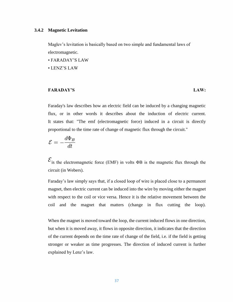
To further understand, consider a coil and permanent magnet as shown in figure. No
change in flux means no current induced. Now consider when the north pole of a
permanent magnet is pushed into a loop (Fig b) the flux increases. An upwards
secondary magnetic field is created that opposes the downward B-field of the magnet,
and thus the current in loop must flow counterclockwise in order to create this
secondary B-field.
When the magnet is removed from the loop (Fig c), the decreasing B-field in the loop
creates a decreasing flux. To oppose this decrease, the current in the loop flows in such
a way that tries to sustain the magnetic field. The current now has to flow clockwise in
order to create a positive secondary flux that tries to counter acts the decreasing flux
due to the with drawl of the permanent magnet.
39
3.4.3 How Magnetic Levitation is achieved
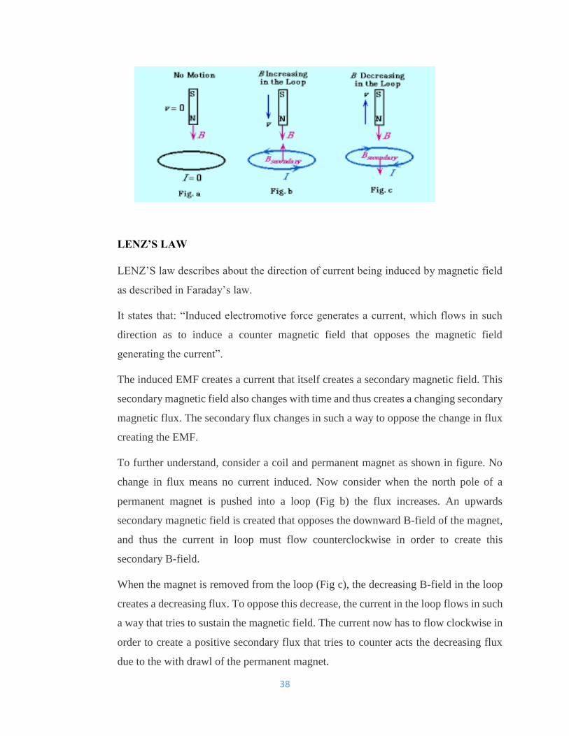
Magnetic levitation can be further understood by considering a current carrying coil.
When current flows through the coil, it induces magnetic field. The change in magnetic
field in the coil due to the change in current induces Eddy current in the metal ring,
which induces magnetic field, as to oppose the field generating it. There repulsive force
of the south-south pole (here) lifts the ring.
There are two types of magnetic levitation.
• Electromagnetic levitation (the ring example)
• Electrodynamics levitation.
40
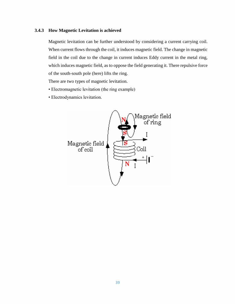
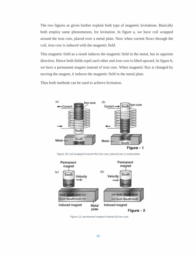
The two figures as given further explain both type of magnetic levitations. Basically
both employ same phenomenon, for levitation. In figure a, we have coil wrapped
around the iron core, placed over a metal plate. Now when current flows through the
coil, iron core is induced with the magnetic field.
This magnetic field as a result induces the magnetic field in the metal, but in opposite
direction. Hence both fields repel each other and iron core is lifted upward. In figure b,
we have a permanent magnet instead of iron core. When magnetic flux is changed by
moving the magnet, it induces the magnetic field in the metal plate.
Thus both methods can be used to achieve levitation.
Figure 10: coil wrapped around the iron core, placed over a metal plate
Figure 11: permanent magnet instead of iron core

41
EXPECTED OUTCOMES
1. The integration of the 3 model components shall be successful
2. The ability to generate power from the 3 components
3. The ability to harvest free energy by integrating the 3 components
4. To gain data from the research based on past projects
5. To be able to simulate the mathematical equations in MATLAB
6. To be able to run the compare the data from MATLAB with actual products.
42
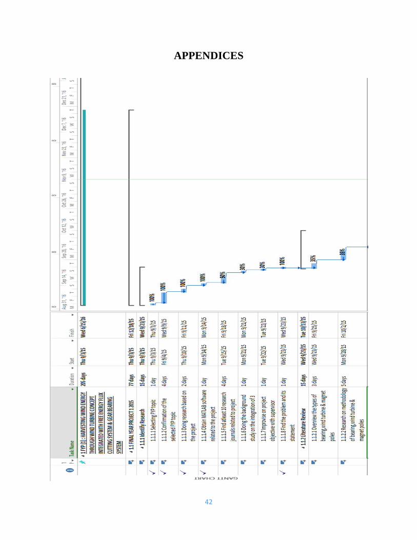
APPENDICES
43
REFERENCES
http://www.scienceclarified.com/everyday/Real-Life-Physics-Vol-3-Biology-Vol-
1/Magnetism.html#ixzz3uJxiiOZZ
PUBLISHED JOURNALS -
SOURCES
1. Linh, N. T., & Anh, N. Q. (2010, January). A Planar Electromagnetic Energy Harvesting Transducer
Using a Multi-Pole Magnetic Plate.DOAJ.
2. Scenna, F., Anaut, D., Passoni, L. I., & Meschino, G. J. (2013). Aerodynamic Analysis and Dynamic
Modeling of Small Horizontal Axis Wind Turbine, SCIENCEDIRECT (Revista SCIENCEDIRECT
America Latina),11(1), 538-544.
3. Scenna, F., Anaut, D., Passoni, L. I., & Meschino, G. J. (2013). Aerodynamic Performance Analysis
of A Flat plate Hawt, IEEE (Revista IEEE America Latina),11(1), 538-544.
4. Imran, A. M., & Kowsalya, M. (2014). An electromagnetic energy harvesting system for low
frequency applications with a passive interface ASIC in standard CMOS. International Journal of
Electrical Power & Energy Systems, 62, 312-322.
5. Tomoiagă, B., Chindriş, M., Sumper, A., Villafafila-Robles, R., & Sudria-Andreu, A. (2013). AN
EXPERIMENTAL STUDY ON THE EFFECTS OF WIND CONDITIONS ON WIND TURBINE
AEROMECHANICS,104, 216-225.
6. Sulaima, M. F., Mohamad, M. F., Jali, M. H., Bukhari, W. M., & Baharom, M. F. (2014, March).
Design and Analysis of Permanent Magnet Linear Synchronous Motor with Special Pole Shape,
2014 IEEE 8th International (pp. 182-187). IEEE.
7. Duan, D. L., Ling, X. D., Wu, X. Y., & Zhong, B. (2015 Electromagnetic Design of a New Electrically
Controlled Magnetic Variable-Speed Gearing Machine, 64, 88-95.
44
8. Song, Z., & Yang, Z. (2013, November). Electromagnetic Flux Analysis of Permanent Magnet
Brushless Motor DC Motor Using Magnet Software, 2013 IEEE (pp. 1-6). IEEE.
9. Zin, A. A. M., Ferdavani, A. K., Bin Khairuddin, A., & Naeini, M. M. (2013 Experimental
verification of computational model for wind turbine blade geometry design, IEEE Transactions
on, 28(2), 1318-1323.
10. Ghasemi, S., & Moshtagh, J. (2014). Failure Mechanism Analysis and Failure Number Prediction
of Wind Turbine Blades, 25, 360-368.