Embed Size (px)
Citation preview
REPORT No. 899
A GENERAL SMALL-DEFLECTION THEORY FOR FLAT SANDWICH PLATES
“ByCHARLESLIBOVEand S. B. B4TDOEF
SUMMARY
.4 smalldejkction theory h dew.?.opedfor the eilm$ic behatiorof orthotropic jla=t plutes in which de$ectiom due to ~hear aretaken into account. In tkk theory, which corers afl types of@t sandtih con.Nruction, a plate is characterized by serenphytical co@ants (jce #Q7nesses and two Pcrieson ratios) ofwhich six are independent. Both the enerqy exprewion. andthe di~erenttil equaki.m.e are dewloped. Boundary condMonscorregpomiing to .m”mply suppotied, clamped, and ela&aliyrestmined edges are considered.
INTRODUCTION
The ad-rent of high-speed flight and_the concurrent neces-sity of maintaining aerodynamically smooth surfaces underhigh stresshave led to the increased study of sandwich-plateconstruction as a possible substitute for sheet-stringer con-struction in airplane design. A sandwich plate consistsessentially of a relatively thick, lowdensity, lowstifhessoore bonded between two thin sheets of high-stillness ma-teriaL MatwiaIs that have been considered for the coreinclude balsa wood, hard foam rubber, cellulose acetate,resin-impregnated cloth fashioned into a honeycomb,corrugated metal sheet, and even closely spaced. stiffenersof the conventional type. The fare sheets may be of metal,plywood, wood-pulp plastic, or some other type of high-stiffness material.
Because of the low-stiffness core, the sandwich plate will,in general, experience appreciable deflection due to shear.Furthermore, because the face sheets or cm-e (or both) mayhave orthotropic stretching properties, the sandwich platewill in general be orthotropic in its flemral properties. &a result, ordinary plate theory, which is based on the assump-tions that the plate is isotropic and that deflections due toshear may be neglected, camot be used to determine thestresses, deflections, or bucklhg loads of sandwich plates.
A generrdsmalIdeflection theory for flat orthotropic platesis therefore developed in which deflections due to shear aretaken into account. The theory is applicable to any typeof orthotropic or isotropic sandwich that behaves essentiallyas a plate, provided certain physical constants are known.These physical constants (two flemral stithases, two shearstifhssea, a twisting stillness, and two Poisson ratios definedin terms of curvatures) serve to describe the plate deforma-tions associated with simple loading conditions and may beregarded as fundamental properties of the plate. Forsimpler types of sandwich construction the physical constantscan be evaluated theoretically from the geometry and physi-cal properties of the materida used. For more complicatedtypes of construction, these constants can be evaluated bymeans of simple test-son samples of the assembled sandwich,
as described in appendk A. A reciprocal relat.iotipbetween the flewral stiffnwwa and Poisson ratios is derivedin appendix B.
& is the case with ordinary plate theory, the orthotropicplate theory consists of two parts, each complete in itself.These parts are a set of six diiTerentialequations, three ofwhich express the equilibrium of an in6nitesimal plate ele-ment and three of which relate the curvatures and twist ofthe element to the forces and moments acting upon it, andan expression for the total potential energy of the systemcomprising the plate and the forces acting upon it. The sixdifferential equations involve six variables. However, it isshown how these simultaneous equationa can be reduced toa si@le equation of si~th order involving any one of the-mriables alone. In appendix C the consistency between thedHerential equations and the potential-energy expression isshow-nby a variational method.
The consideration of deflections due to shear makes neces-sary the specification of one more boundary condition thanin ordinary plate theory. T&s fact was first appreciated byReiasner in reference 1. Because of some arbitrariness in thechoice of the additional boundary condition, two types ofsimple support and two types of clamped edges are possible.Furthermore, three boundary conditions can be specifiedfor a free edge, in contrast to ordinary plate theory. Bound-ary conditions more general than freedom, simple support,or clamping are considered in appendix C.
A number of investigations related to the problem of ortho-tropic- or isotropic-sandwich-plate amdysis have been madepreviously. Theories for the bending of orthotropic platesdue to lateral loada and buckling due to edge loads, neglectingdeflections due to shear, are given in references 2, 3, and 4and pages 380-384 of reference 5. The effect of shear onthe bending clue to lateral load of homogeneous isotropicplates nnd isotropic sandwich plates is considered in refer-ence 6. The effect of shear on the bending due to uniformlateral load and buckling due to edge compression of simplysupported isotropic sandwich plates with homogeneous coresis considered in investigations by Hopkins and Pearson andby Leggett and Hopkins. A rough method of tUing. intoaccount deflections due to ahear in the buckling of simplysupported orthotropic sandwich plates is used in reference 7.
The present theory may be regarded as a natural exten-sion to pMes of the approximate theory used in pages 170–174 of reference 8 to take into account deflections due toshear in a beam. The theory of this paper is more generalthan the aforeme.ntioned theories in that it apphs to ortho-tropic or isotropic sandwich plates with homogeneous ornonhomogeneous cores and with arbitrary boundary condi-tions, it presents both the differential equations and the
139
.—
140 REPORT NCL 899-N-4TKU’L4L A?WSoEY: co~~r~.~ Fo.R4@oNA~1cS .—
energy expression for the plate, and it is applicable to prob-lems that involve lateral as well as edge loads.The differentialequations of the present theory are reduced to special formsin order that they may he ‘compared with the. equatio~obtained in references 5 and 6. ..
The detailed development of the theory comprises -mostof the following aecticms and the appendixes. The mainparts of the theory are summarized bridly in a section entitled“Recapitulation of Principal Results.”
SYMBOLS
orthogonal coordinates; z measumd normal toplane of plate and x an&y parallel to principal~~es of flexural symmetry, inches
deflection of middle surface of plate, measuredin z-direction, inches - . .-
intensity of lateral loading, pounds per sqyareinch
intensity of tit.ernal slum.actirig in z-directionin a cross section originally paralleltmyz-plane,pounds pcr inch
intensity of internal shear acting in z-direction ina cross section originalityparallel to zz-plane,pounds per inch
i,utemity of internal bending moment [email protected] a cross section mrighally parallel toyz-plane, inch-pounds per inch
intensity of inter:al bending moment. actingupon a cross section originally parallel tozs-plane, inch-pounds per inch
intensity of internal twisting moment acting in across section originally parallel to #z-plane orzz-plane, inch-pounds pgr inch
—.C
/1qckcdw
Itl- Z I
N.
Nu
N=,
D;j D, --
Din . .
~- --
.DQZ,Dog
k) Py
P7.? TV
ha, b
vv, “--””-Ku, ‘0
intensity of middle-plane tensile force pmallel to*z-plane, pounds per inch .-.
intensity of middle-plane tensile force.parallel toyz-plane, pounds pm inch
intensity of middh+pkme shearing force pmallolto yz-plane and m-plane, pounds per inch
flexural stifl%~es of plate with anticlaeticbending unrestrained, ~nch-pou&ls
?
ending momont per inchCurvature “)
twisting stiffness of plate, inch-pounds—
(Twisting moment per inchTwist )
“flexuralstiffness of ordinary plate, inch-poundsshear stiflnessw of plate, pounds pcr inchPoisson ratios for platu, defined in tvrrns of
curvaturesPoisson ratio for ordinary plateshear-strain angles clue to shyure Q. and Q“,
respectively, radiansthicliness of plate, inc.hcslengt,h and width, respectivcly, of rectangular
plate, inche9total potentitd energy of system, inch-poundsstrtiinenergy of bending of plate, inch-poundspote@ial energy of external loads, inch-pounds-displacements in z-direction ancl y-direction,
respectively, of a point in middlc surface ofplate, inchss
[Dl, Ml, [Nl, [~] diffmential operatcn~SIGN CONVENTION
The @ convention and notation usccl in the prescn~paper are, wherever convenient, the same -as those used byTirgoshmko ti ref~ence .5. _.
h
‘*
/ I Qziiyq/dx @d.
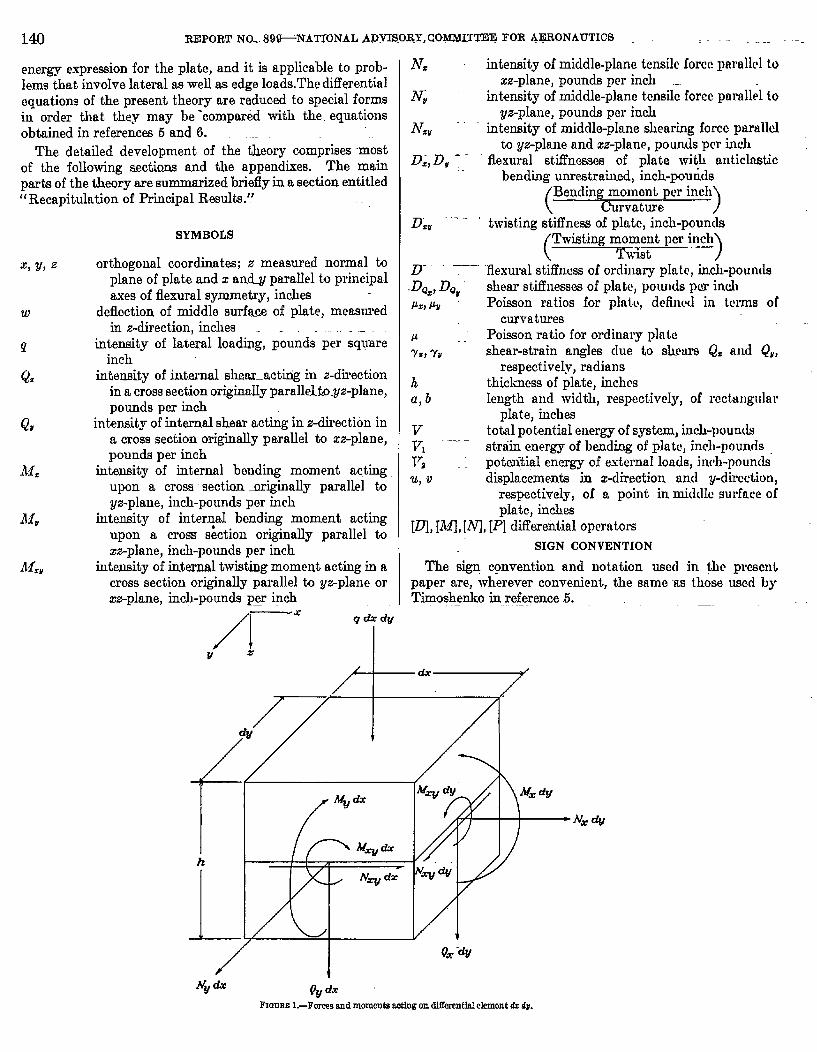
FIGUREl.—Foreegandmomentamttngondlflemntldelement& .4v.
A GENERAL S.MALL-DEFLECTION THEORY FOR FLAT SANDWICH PL4TES 141
The r-, y-, and z-axes of an orthogonal coordinate systemare oriented so that the zy-plane coincidgs with the undis-torted middle pkme of the plate. Deflections w are measurednormal to the ~-plane and are positive in the positive direc-tion of the z-axis. The Meral load g is also positive in thedirection of the -axis.
The internaI sheam Q. and Qr,moments M= Mr, and Ma,and middle-plane forces A.L=,iVr,and N.=Mare shown in iigure 1acting in their positive directions upon an infinitesimalelement of Iength dx and width dy cut from the unloadedplate by planes parallel to the ZZ- and yz-pIanes. Ody theforces and moments acting on two adjacent faces of theelement are shown. The forces and moments on the oppo-site faces cfitlerfrom those on the faces shown only by infini-t&maI amounts. The directions in which they act, however,are opposite (for exampIe, moment M. dy on the face shownis counterclockwise; moment M= dy on the opposite facewould be shown acting clockwise). The twisting momentand middIe-pIane shearing force acting on any cross sectionare known, from equilibrium considerations, to be equal tothe twisting moment and middle-plane shearing force actingon a cross section at right angles. The symbols M=Vand N=vtherefore appear in both of the faces shown in figure 1.
For convenience, in this report the z-direction is sometimesreferred to as the vertical direction and pkmes paraIleI tothe ~-plane are sametimes referred to as horizontal planes.
PHYSICALCONSTANTS
The physicaI properties of the plate are described by meansof seven constants: the fle.xuralstiffnessesD=and DU,the twist-ing stiffness D=Y, the transverse shear stiffncmes ~Q= and~Qr, and the Poison ratios p. and P“. Definitions of theseconstants are obtained by considering the distortions of theditlerentialelement of figure 1under simple loading conditions.
Let a~lforces and moments acting on the element be zero,except for the moments M. acting on two opposite faces. The
efbct of M= is to produce a primary curvaturez in the
middle surface of the element and also a secondary curvaturea%~ which is a Poisson eflect. Then D= is defind as the
negative of the ratio of moment to primary curvature or
D.= –’~ (1)
T2
when only M. is acting, and ~=is defined as the negative ofthe ratio of Poisson curvature to primary curvature or
Vw
~z=x2FW (2)
5?
when only ilf. is acting. hro other distortions are assumedbut ~ and&w ~hm ~f acts
a2 ~=” The minus signs are intro-
duced in order to make D= and p= essentially positivequantities.
Simiiarly, D, and p, are defined as
~= i&u ‘a~w (3)
WZFwa2
“= –Fwbf
vrhe; only Mr is acting.
(4)
If, now, all of the forces and moments are equaI h zeroexcept M.p acting on all four faces, the onIy distortion
produced is a twist ~%–, and D=, is defied as the ratio ofax~twisting moment to twist or
D.”=+ (5)
ax~when only MW is acting.
The transv~e shear stiffnessDQ=is defied by lett~ingoglythe shears Q. act on opposite faces of the element-(except foran infinitesimal moment of magnitude Q, dy dx required forequill%rium). The distortion is assumed for the momentto be essentially a sliding of one face of the element withrespect to the opposite face, both faces remaining plane, Asa result of this sIiding, the two”faces parallel to the z-planeare distorted from their rectangular shape into paralIel&ramsby an amount 7Z, which is the shear angle measured in thexz-plane. The shear st.iinws DQCis defined as the ratio ofshear to shear angle or
Q.D%=% (6)
when onIy Q=is acting. If the sides of the eIement are keptparallel to the z-axis, the slope of the middle surface is ._
w-henonly Q=is acting.Jn a simiIar manner, the shear stiflness DQ, is defined as
the ratio of the shear on the faces parallel to the z*pIane to .the shear angle measured in the yz-plane when only Q, isacting or
(7)
when only Q~is acting. If aII sides of the element are keptparaIlel to the z-axis, the elope produced is
when only Q&is acting.
The constants just discussed serve to define the orthotropicsandwich plate; they can be evaluated theoretically if theproperties of the component parts of the sandwich are knownand if the p~ateis of simple construction. In any event., the
142 REPORT NO. 899—NATIONAL ADVISORY COMMITTEE FOR AERONAUTICS
coustants can be determined experimentally by means ofbending tests and twisting tests on beams and panels of thesame sandwich construction as the p~ate. A description ofthe tests required is given in nppe.ndixA.
AIthough seven physical comstantshave been. discussed,they need not.all be independently determined for if any threeof the four constants D., DV,P., and ~tiare know-nthe fourthcan be evaluated from the relationship
/.L=DU= @= “ (8)
This relationship, based on a genendization of llaxu7c11’s.reciprocal law, is derived in appendix B.
The shear stiffnesses DQ, and D~, merit some additionaldiscussion. ‘HE distortion due to shear was assumed to bea sliding of tlm cross.sections over each other, the cross see-.tions remaining plane and the shear strains remaining con-stmt for the entire thickness of the plate and equal to. thoshear angle 7* or 7r. Actwdly, if the plate is continuousenough for cross sections to exist at aII,under shear the crosssections generally tend to warp out of their plane condition(p. 170 of reference 8); this warping makes the shear angle,as defined for equations (6) and (7), meaningl~s. The shearstrain varies with depth and an average shear strain wiUhaveto be used as the effective shear angle 7= or YVfor purposmof defining effective shear stiflness Daz or DaV. If the exper-imental method is used. (sew appendix A), this difhdty isnot encountered because, instead of a shear angle, curvaturesare measured, and the stiffmssw. obtained are autcmmticallythe effective stifl%essw.
Daspite the general tendency of crow sections under shearto warp, the assumption that they remain plane (though notnormal to the middle surface) can bo. shown to. be almost..correct for those sandwich= in which the stiffness of thecore is very small compared with ths .stiflness of. the faces(for example, Metalite, honeycomb). For such sandwichesthe shear stdlnesses Du= and D@~cau.be readily calculatecl,because the faces may be resumed to take alI the direct bend-ing stress and the vertical shear may thmefore be assumeduniformly distributed in the core. The shear angles ~= and7Wwill then be constant throughout the core.
For those sandwiched in which cross sections under shearmay not ba wmmed to remain plane, the tendency of thesecross sections to warp introducw a further complicationwhich can, however, be resolved by means of a justifiablesimplifying assumption. This compljcation is due to thefact that if the cross-sectional warping is partially or com-pletdy prevented the effect will be to increase. the shearstiffness DQZor DQV. The shear stiffnesses, thus, depend notonly on the properties of the plate materials but also on the.degree of restraint against cross-sectional warping. For thepurpose of the present theory the shear stiffnesses D~z andD~, are assumed to be constant throughout the. plate anclhave the values tlmy would have if cross sections were alIowedto warp freely. The error caused by this assumption willbe mainly local in character, being most pronounced. in theregion of a concentrated Iateral load, where a sudden changein the shear tends to produce a sudden change in the degree
of warping which is prevented by continuity of the platv.The error wiIIprobably bo mgligiblo in the cuse of distribululkinds, for which there are only gradual changm in the shww.A discussion of this erm.rin connection with bcama is con-tained in pagss 173=174 o[.reference. 8 am..in rcfercn.cc 0,
. .DIFFERENTIALEQUATIONSFOlt PLATE
DISTORTIONEQUATIONS
NWEquiitious can be derived relating the curvatures ~~ and
ah VW“~ and‘he‘Jvistaxay— at any point in thtiplate h the iuicr-
nal shears nnd moments acting at that point.
Equation for the curvature #.—An expression can h!. ...
obtain<[. for the total curvature a~ in the x-direction ~y
adding together the contributions mado by each of W slwmsand moments acting separately.” From equation (I) thecurvature co~tributed by ill. is found to bo
–J* .,
Equations @) and (4) can be solved for tho ccmtribllti~l~to.azw~ by .31, which is
Finallyj “tlm equation following equation (6) imlicatcs thtiLaQ.
the ex~t~nceof ~ Preduces a curvaturo in the middl~
plane equal to
The moment iifz, and t,heshear Qvmnke no contribution toa’w -~. Addition of the three component curvnturcs gives
. &w itfz AIM—=-a~ @,n+&=~ (9a)
Equation for the mrvature ~~.—Sii1ar considerations*
give the curvature in the y-direction as .
(w.))
a’w-—.—Ancsprussion for the t.wis~‘quation ‘or ‘he ‘Wist bXhJ
atwZ& is obtained by fimt writing an expression for the twis~
ing moment iW=Yin terms of the distortions of the clcmcnLdx dy. ‘“””
Let the middle surface of the element ho distort~d so thtiLa=w
‘t acqfi:resa“f’ktaxa~.Furthr awurne that each line
elemen$aormal to this m-iddlcsurficc before its distmtitm (a)fkt rotates .s0.ss to remain normal @ it afW its distqrtignl
A GENERAL SMALL-DEFLECTION THEORY FOR FIAT SAh~’iV’ICHPLATES
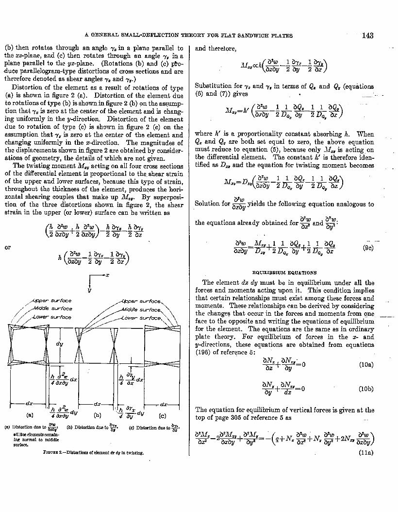
(b) then rotates through an angle ~. in a plane parallel tothe zz-plane, and (c) then rotates through an angle ~Y in aplane parallel to the yz-phme. (Rotations (b) and (c) p!-o-duce parallelogram-type distortions of cross sections and aretherefore denoted as shear angles ~. and 7,.)
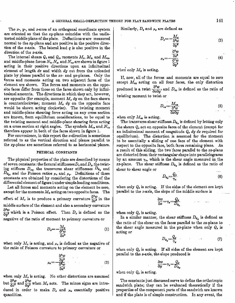
Distortion of the element as a result of rotations of type(a) is shown in figure 2 (a). Distortion of the element dueto rotations of type (b) is shown in figure 2 (b) on the assump-tion that y= is zero at the center of the element and is chang-ing uniformly in the ydirection. Distortion of the elementdue to rotation of type (c) iE show-n in figure 2- (c] on theassumption that 7Vis zero at the center of the element andchanging uniforndy in the xdirection. The magnitudes ofthe dispkicementashown in figure 2 are obtained by conaider-atione of geometry, the details of which are not given.
The twisting moment bl= acting on alI four cross sectionsof the differential element is proportional to the,shear strainof the upper and low-ersurfaces, because this type of strain,throughout the thickness of the ekment, produces the hori-zontal shearing coup~es that make up M=. By superposi-tion of the three distortions shown in figure 2, the shearstrain in the upper (or lower) surface can be written as
(h b%O h a%
)h a~z h?ky,.—
2 axqf+2m ‘–—––—2* 2ax
or
(ah I*Z Ih,‘aXZMJ 2aY 2ax )
———— —_
t-’-i~d~ t- f’+,,,t’j .,z l-+-l(a) ——sig4 tidy (b) — dy
4 dy (c)
(a) I)fstartlondue to ~FY RI) D-n &m to as. (c) DIst.ertImsdueto~.allUneelemwtsremaiu-ing normal to ndddIeSorka
F1aumt2.-Distortkmgotekmentdr dfl in hvhting.
143
Substitution for ~=and 7Yin terms of Q. and QF{equations(6) and (7)) give ,
where k’ is a proportionality constant absorbing h. WhenQ. and Q, are both set equal to zero, the above equationmust reduce to equation (5), because only ..W:ris acting. onthe dtierential element.. The constant h’ is therefore iden-tified as D- and the equation for twisting moment becomes .. _
(a’w I I aQr I 1 aQ,M,,=D., —–– — — ––— —axay 2 D~z aY 2 Da, ax)
VW“elds the following equation analogous to,sO1utiOn‘or ~ ~
the equations already obtained for ~$ and a~w:*
EQUILIBRIUMEQUATIONS
The element dx dy must be in equilibrium under all theforces and moments acting upon it. This condition impliesthat certain relationships must exist among these forcw andmoments. These reIationsbips can be derived by consideringthe changes that occur in the forces and moments from One __..face to the opposite and writing the equations of equilibriumfor the element.. The equations are the same as in ordinaryplate theory. For equilibrium of forces in the x- andydirections, these equations are obtained from equationa(196) of reference 5:
(lOa)
(lob)
The equation for equilibrium of vertical forces is given at thetop of page 305 of reference 5 as

14.4 REPORT NO. 89 fiNATIONAL ADVISORY COMMITTEE FOR AERONAUTICS —
And the equations for equilibrium of moments about the V-and x-axes are obtained from equations (188) and (189) ofreference 5 a5
Qz=–~+a$j ~ (Ilb)
(llC)
(Equations (11) are also derived in appendix C by minimiza-tion of the potentigJ energy.) Note that the left-hand sideof equation (1la) can, by virtue of equations (1lb) and (llc),besimpIified. to _.. .
If, as is customary in small-deflection theory, the middle-plane stressesN=, IVV,and N,r are aiiumed to be unchangedin the course of the plate’s deffection and equal to theirinitialvalues before application of lateral load, then equations (10)are automatically satisfied and equations (9) and (11) con-stitute the six fundamental dMerential equations that deter-mine the .forcea, moments, afid distortions throughout. the
orthotropic plate, They can be used in their present form orin the alternate-form obtained in th~ following section.
●
ALTERNATEFORhl OF THE DIFFERENTIALEQUATIONS
The fundamental diflerentia] equntions (9) and (11) can betransformed so as to separate variables. Equations (9) amii-at solved for ill=, Jlv, and iM=Vta obtain
With the left-hand side of equation (1la) simplified to
aQz aQff d the above expressions for all., MV, and M.E~ +~an
substituted into equations (1lb) and (1lc), equations (11)beconm, after some regrouping of terms,
( ‘)”+(a~~+(aQ,=-’‘=~+N;$+2NZVam
These three equations can be solved to obtain a differential equation for w alone in terms of q, an equation for Q.alone interms of g, and an equation for QPalone in terms of q. This separation is accomplished most easily, for the cam in whichN,, N,, and N=r are constant” throughout the plate, by treating the three differential equations as though they were alge-braic equations and solving for w, Q., and QUby means of determinants. The terms in the determinants arc tho difFrrcntial-operator coefficients of w, Q=,and QVappearing in the three equations. ‘In expanding these determinants, the rule for muh i-pIication of linear operators must be used. For example,
k a result of such a solution, the following differential equations are obtained for w, Q=,and Q,:
[D]ti=-[Mlg (13a)
[D]Qz= –[NJq ““- (13b)
[DIQ,= –[P]g (13C)
Equations (12) and (13) taken together conatitut~ an alter-nate set of difkrential equations that the plate must satisfy.
COMPARISONSWITE PBEVIOUSSOLUTIONS
Homogeneous isotropio plates, deflections due to shearneglected.—l?he usuai fourth-order equation for homogene-ous isotropic plates, in which deflections due to shear areneglected, can be obtained from equation (13a) by Ietting
DQ==DQZ= w
~=pv=p
D== D,= D(l–P’)
D.V=D(l–A)
‘il’ith these substitutions made, equation (13a) becomes, aftersome transposition of terms,
which is the same as equation (197) of reference 5.Isotropio sandwich plates, defections due to shear “”
considered, —The differentialequations for isotropic ?apdfigh .... _plates are obtained in reference 6 by use of Castigliano’stheorem of least work for the case in which the middle-surface forces N=, iVv, and N*Vare zeio. The equilibriumditlerentia.1equations of reference 6 are equivalent to equa-tions (11) of the pr&_ent paper. Equations (lOa), (lOd),(lO@), and (lOf) of reference 6 can be solved ainmltamcmalyto obtain the following equations for the curvatures andtwist in terms of the vertical shears and moments (thenotation is that of reference 6):
.
146 REPORT hw: 89*NAT10NAL- AbVISORY [email protected] FtiR ‘[email protected] “..- .—.
The symboIs H, 1~, and I“rin the above equations corres~ondto -JIJzr, Q., and QP,respectively, in the notation of thepresent paper. The quti.ntitiesD, C!; C.; and “Vare phy~icalconstants for the plate. The above equations are seen to beidenticd in form to equations (9}. of the present paper (if.~Q_=is set equal to Da- for”isotropY in the w aml”‘y-directions)”
‘-’P av’)i*’’c”-except for the ad~tional term ~ ax +=
ture equation. This term arises from the consideration ofstresses and strains in the vertical direction, which were neg-Iected in the present paper on the ground that they have [email protected] on the over-ail ffexud behavior of the plateand are only impurtant in the neighborhood of concentratedloads. Setting C’. equal to infidy makes the equationsderived from reference 6 completely identical in form to.equa-tions (9) of the present paper. It.should be rnentiomd thatthe quantity was used in reference.6 is not the deflection ofthe middle surface but “a weighted average &crossthe thick-ness of the deflectkms of all points of the plate which lie on anormrd to the middle surface,”
BOUNDARYCONDITIONS
The boundary conditions are first discussed for themetypesof edge support most commonly assumedin practice:. namely,complete freedom, simple support, and damping. (MoregeneraI kinds of support are. considered in appendix C.)Theee supports are characterized by the condition that nowork is done by the moments and vertical forces at thoboundary. A boundary parallel to the y-axis is considered;the conditions for a bounclary paralkl. to the z-axis can beobtained by replacing x by y and vice versa, except in thesubscripts of Al=Vand iV=V. ““ ““ “-”””“’- ““
Free e~e.—The boundary conditions for a free unloadededge parallel to the y-axis express the conditions of zerobending moments, zero twisting moment, and zero verticalforce, or
ilzx =0 _. (15a)
M.,=o (15b)
Q==0 (MC)
If the free edge carries load, the middle-plane forces IV, andNzy will not in general be zero and the boundary conditionof zero net vertical force becomes
(i5c’)
instead of equation (15c) .“
Simply supported edge.—The principal boundary con-ditions for a simply supported edge parallel to the y-axis arew= O and ikft= O. If to these two conditions is added therestriction that there is. no y-displacement of points inthe boundary, then the shear angIe vu is zero and thereforeQ,~v=o. If, on the other hand, the support at the boundary
is applkd onIy to the middle surface at the boundmy and nohorizontal forces are applied to prevent,the @spkwwnent ofother points in the bo,undary, then h~=~,which is maclc up ofsuch horizontal forces, must be zero. Two different types ofsimple support thus emerge. For simple support in whirh allpoints .in the boundary are prevented from moving pmallclto the edge, the conditions are
W=() (16a)
ill== o (ltw)
Q.~=o (lGC)
For shple support in which all points in tho boundmy,except those in the middle surface, are free t.omove paralhdto the “edge, the conditions are
WC() (17a)
. M*=O (12%)
.Jfz,=o (17C)
Of th Iii.o type&of simple support, the first (cqua~ions 16))is raor~liiely to occur in practice.
Clamped edge ,—The principal conditions characterizinga clamped edge paralleI to the y-axis are zero deflection of themiddle surface and zero rotation of the cross scctione makil]gup the boundary (that is, the boundary pkmc remains parrdlrIto the z-axis). The requiranent of zero deflection is satisfiwlby letting io= O at the boundary. The rcquiremcnL thaLboundary cross sections remain parallel to the -axis is satis-
“aw &fied by letting ~ ‘DQ= Jas the equation following equation (G)
indicates. (Note that if ~leflections clue to shear arr
neglected by let.t@g 11~==w, then the ktst.boundary comti-
tion reducw to ~= O, which is familiar in ordinnry plut~
theory.) Just as in the case of simple support, the third
‘~ –O or i’ll=r=O deprndiilg onbound~y condition is either ~a,–
whether or not points in the boundary (other than thosepoints in the middle surface) are prevented from mo~’i.ngparallel. .ti the edge. Thus, two types of clamping arcpossible. For a clamped edge in which the points in theboundaiy of the plate are prevented from moving parallelto the edge, the conditions are
W=o (18a)
(18.b)
Q,To (18C]
For a clamped edge in which the points in the boundary
A GENERAL S.MALL-DEFLECTION THEORY FOR PLAT SANDWICH PLATES 147
(except those in the middle surface) are free to move paraIleIto the edge, the conditions are
~= o (19a)
aw Q,_.rx-~– (19b)
Ji=,=o (19C)
The Iatter type of clamping is very unlikely to occur in prac-tice, because any practical type of restraint that keeps theboundary from rotating has to be applied over an appreciablepm-tof the thickness of the edge and therefore prevents mostpoints in the boundary from moving freely paraIIeI to theedge.
The boundary conditions just discussed, as well as bound-ary conditions corresponding to more general types ofsupport, are derived b appendix C by a variational method.
POTENTIAL-ENERGYEXPRESSIO~STRAINENERGY
An eqmssion Cm be obtained for the strain energy T“lproduced by the moments 31., 31U,and IIIfi and the shearsQ. and Q, by considering the work done by these momentsand shears in distorting the differential ekment of figure 1.
The work of the moments III, dy is equal to ~ M= dy times
the counterclockwise rotation of the right-hand face withrespect to the left-hand face of the element. This rotat~onis made up of two parts: the rotation caused by the moment31=itself and the Poisson rotation caused by the moment 31,.
The sum of these two parts is –31=
( )–m~+p, ~ dx. mote
~Q. ‘that although, the term ~ makes a contribution to ~he
cm-vature of the.middle surface, this term represents a ratrof change of shdmg rather than a.rate of change of rotatiouand therefore makes no contribution to the rotation of oneface with rwpect ta the opposite.) The work of the moments.V, is therefore
or
similarly, the work of the rnomenb 31. is
(1 .M”2 M M)
——P=+ dxdy2D8=
(20)
(21)
The work of those moments Jfzr acting in the faces pmdlel
to the zz-plane is equal to # ilfZvdx times.the clockvise rota-.tion of the nearer face (as seen in fig. 1) with respect to the
farther face. This rotation is made up ot the two partsshown in figures 2(a) and 2(b) and is equal to ,..——
or, replacing y. by its equivalent in terms of Q=(equation (6)), -.
The work of the moments M=, paraLIelto the zz-plane istherefore
SimilarIy, the work of those moments .& parallel to the
The total -work of the momenlx J1=, is, by adding the lasttwo expressions,
The factor in parentheses is timply ~~~ from the eq~lation
preceding equation (9c), and the work of the moments 31.,therefore becomes
.
Jf=:~dxdy (Zzj
distance through which the right-hand face slicles:_yithrespect to the left-hand face. T~s dist~ce ~” ‘YZdr and-
-wor~ is therefore ~ Q.y. dx 4). W18 c’c’mentOf YX”‘Y ‘ts
equivalent in terms of Q=gives
(23)
for the work of the shears Q.. Similarly, the work of theshears QPis
(24)
Integration of the energy expressions (20) tO (24) o~ef the. . .. .entire plate gives, as the total strain energy due to bendingand shear,
(25)
148 REPORT NO; 899—NATIoNAL ADVISORY COMMITTEE FOR AERONAUTICS
Elimination of .ikfZ,A& and A& by use of equations “(12) transforms the strai&nergy expression (25) into
In addition to the strain energy of bending and shear, there is the energy of stretching of the middle surface produc.eclby the forces AT.,Al,, and iVzV In small-deflection theory, these forces ire assumed to remain constant during lateral deflec-tion. The strain energy of middle-surface stretching is therefore a constant. independent of the lateral defkwtion. Thisenergy does not af7ect any solution and may be omitted from consideration.
POTENTIALENERGYOFEXTERNALFORCES
The potentiaI energy acquired by the ext.ernaIforcw in the course of the Iateral deflection of the plata is ind.epcndcntof the internal construction details of the plate and depends only on the displacement.sof the middle.surface. The potential-energy expressionfor the orthotropic sandwich plate is therefore the same as for the ordinary homogeneous isotropic plate; t.htitpart of the expression due to the forces N., N,, and N=, at the%oundtiries is given by the negative of expression (201) ofreference 5. If to this part is added the potential energy acquired by the lateral Ioads, the resulting expressionfor tho po(cntialenergy of the external forces is
(27)
Equation (27) appliea only when the reactions do no work and thereforo acquire no potential energy in the coum of theplate’s deflection. The most commonly assumed boundaries satisfying this condition are free, simply supported, and cIampcdedges. Tho potentiaI-energy expression for plates with more geneial boundary conditions must irdudo terms corrce,pondingto the work of the reaction forces. This more generaI case is considered in appendix C.
In this section equation (27) has been established by means of physical reasoning. A more rigorous derivation of equa-tion (27) for the special case of a rectangular plate is given in appendix D.
POTENTIAL ENERGY OF SYSTEM
The total potential energy V of the system comprising the plate and the forces acting on it is the sum of the strain cnorgyV, and the poteu tital energy of the external forces V,”or, by addition cd equations (26) and (27),
(28)
The above expression applies when the bounda~T reactions do no work and therefore acquire no potential e~crgy in thecourse of the plate’s deflection. This equation is therefore applicable when the edges of the plate tirefrcw,simply supportcd,or cknped. The potential-energy expression for a plate with more general boundary conditions is given in appendix C.
A GENERAL SJ.WLL-DEFLECTIO.X THEORY FOR FLAT SANDWICH PIATES 149
RECAPITULATIONOF PRINCIPALRESULTS
1. The physical properties needed for smaI1-deflectionanalysis of an orthotropic plate in which deflections due totransverse shear are to be considered are the flemd stiff-neases D= and D“, the corresponding Potion ratios p. andI.LYdefined in terms of curvatures, the twisting stiffness D.u,and the transverse shear stiflnesses D~zand DQr. Theseconstunts can be evaluated theoretically or by. tests onsamples of the plate as described in appendix A. Four ofthese constants are related by the reciprocal relationshipp=Dr=pWD, d&ved in appendLxB.
!?. The differential equations relating the deflection w,the lateral load g, and the internal forces and moments N=,A’,, N,u, Q,, Q,, hf., M,, and .Wv m
a~w 1 aQ=– –~+P” ~;’+D; ~=2 –
relating distortions to distorting moments and forcw, and
‘,, M-f,Q,..%+=
for equilibrium.
:3. The fist three equations can be sol-red for -31=,.MW,andM& to obtain
Substitution of these expressionstito the Iast three equationsand soIution of the resulting equationa by means of opera-tional determinants give the following differential equationswith variables separated, for the case in which N,, IVr, and~=r are constant throughout the plate:
[DJw= –[M]q
[D] Q,= –[N’Jq -
[DIQ,=-[~1~
where [D], [M’J,[.h’1,and [~ are differential operators definedby equations (14).
4. Three types of support commonly assumed at theboundaries of a plate are no support. (free edge), simplesupport, and clamping. These types of support can bedescribed in terms of deflection, shears, and moments for anedge paralleI to the y-axis as follows:For a free edge,
Alz=o
34.,= o
For a simply supported edge at which the support is appliedover the entice thickness,
‘W=()
Al==o
%u
For a simply supported edge atonIy to the middle surface,
W=o
M==o
AI=,=()
which the support is applied
For a clamped edge at which the support is applied over theentire thickness,
.U)=O
For a clamped edge at which the support is appIied only tothe middle surface (a type of support very unlikely to bemet in practice),
aw (?z=o——ax DGZ
M=,=o
The conditions for an edge parallel to the z-axis can bewritten by replacing z by y and vice versa, except in thesubscripts of & and N=u.
Boundary conditions can also be written for more generaltypes of support. (See appendix C.)
150 REPORT NO. 89~—NATIONAL ADVISORY [email protected]~E FOR AERONAUTICS
5. The potential energy of a plate in Tvbich the nliddle-surface forms are assumed ta remmin unchanged fi.. thecourse of the plata’s deflection and for which the momentsand -mrtical forces at the “boundariesdo no work is
The most important types of boundary to which this cxprea-sion appIies are free, simply supporhxl, or cIampcd. Formore general types of support, in which the boundary reac-tions do work in the course of the pkd.c’s ddlcction, thepotential-energy expression must ho cwhmdwl 10 includeterms representing the potential energy of the reactions.
The. calculus of variatio& can be used to show thtit inorder for the. potential energy to be .a mh.timumtbc clitler-ential equations of equilibrium and the boundary conditionsmust be satisfied. (See appemlix C.)
LANGLEY filEMORIAL AERONAUTICAL LABORATORY,NATIONAL ADVISORY COMMITTEEFOR AERONAUTICS,
LASGLEY FIELD, VA., September M, 1947.
APPENDIX A
TESTSTO-DETERMINEPHYSICALCOIWTA~TS
The purpose of this appendix is to give descriptions ofpossible tests for deterruining the physical constants. No”-consideration has been given to details of testing tecbmiclue.Practic.aI considerations may dictate. changes in the, testprocedures described or the. quantities to be measured.These chmg-, however, willnot be of fundamental importance.
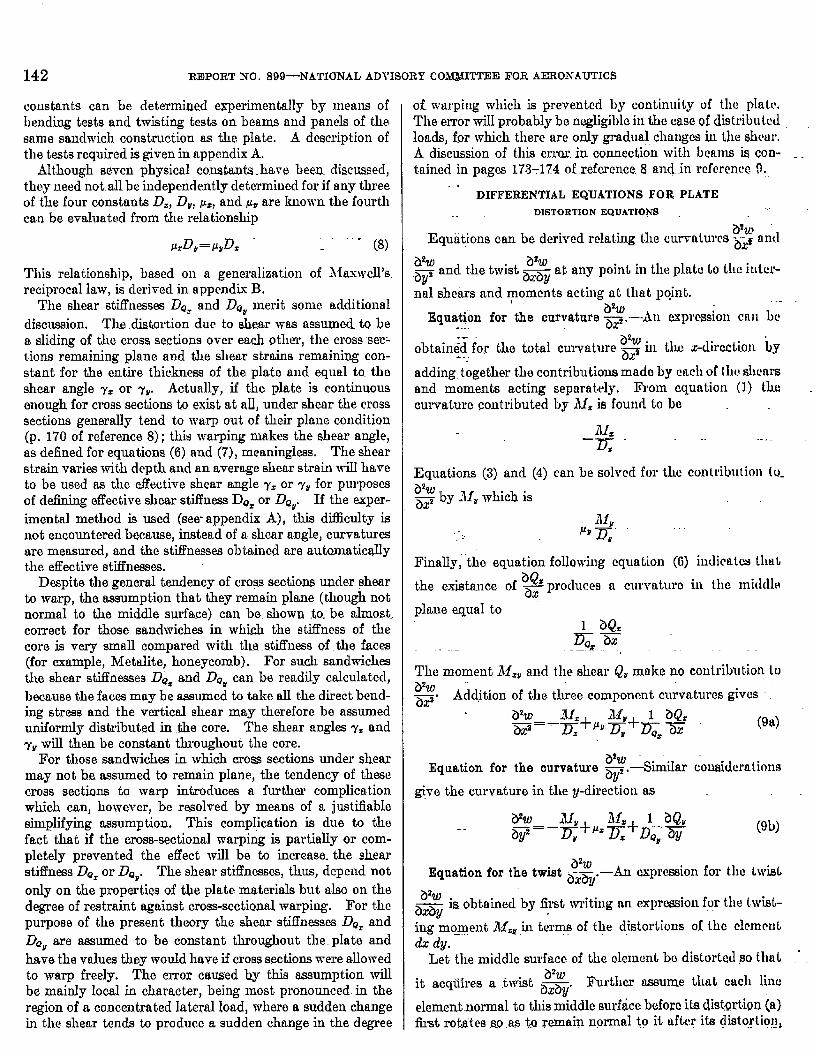
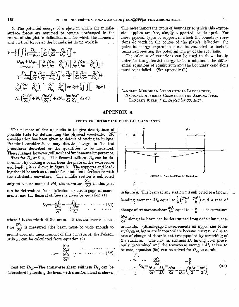
Test for D= and p=.—’l%e flexural stifluessD.can be de-termined by cutting a beam from the plate in the z-directionaud Ioading it as shown ~ figure 3. The supports and load-ing should be such as.to ma-ke”for&urn interfeienc.ewiththe anticlastic curvature. .The middle section is subjectid
a%only to a pure moment Pd; the curvat~lrg ~ in this part
can be determined from deflection or strain-gage measure-ments, and the flexural stiflnese is given by equation (1):
D=–..j??~–~w-. -...... (Al)
a~ 6=--””
where 6 is the width..of .thc beam. If the transverse cur_ra-
ture ad is measured (the beam must be wide enough to
permit acc~te measurement of this curvature), the Poisson.ratio pZ can be calm.lated from equation (2):
VW~
&~=—~ .:...-..: .... -..(Az)2iF -
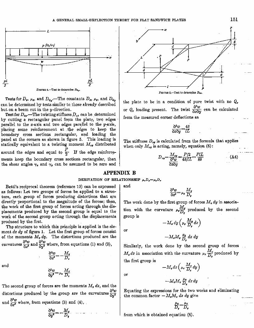
Test for Da=.—The transverse shear stifl’ness D~=can bedetermined by loading the beam with a uniform load asshown
t-, ,
P P-
i=) ~—d—
t
---- m ------’-
T—-----------
b ‘-
—x
FIGURE 8.—Test to dctemdncD, andIL,,
in figurej4. ”The beam at any station z is subjected to u knowu.
‘w-) :bend~- moment Alz equal to ~ and a rnte of~,.
t)’.ichange of transverse shear ~ equal to —”. The curvature
a’w P~ along the beam can be determined from defection mmM-
uremeg$.s. (Strain-gage measurements on upprr and lowersurfacm “of beam me inappropriate because curvature due torate”of .@mge of s~egr is.not aceompgnicd by strctchiug o{the surfaces.) The flexural stifkss D.having bum prcvi-cmsly determined and the transverse momcut ~l~rttiken tobe zero, equation (9a) can be solved for 23*=to obtain
----
a’. ,- P—=
=+~z-*) ‘A’)~..DQZ= ~==a w
.,_..:
A GENERAL SMALL-DEFLECTION THEORl” FOR FLAT SANDWICH PIu4TES 151
pi~
I?ICWEE 4.-Teat to determine Da=.
Tests for D~, Pr, and D*ti,-The cowtantscan be determined by tesk- simiIar to those already describedbut on a beam cut in the y-direction.
Test for D,V,—The twisting stiffne~.DzY cm be determinedby cutting a rectangular pnnel from the plat~, t~o edgcwpmdel to the x-axis and two edges paraLleIto the y-axis,placing some reinforcement at the edges to keep theboundary moss sections rectangtdar, and loadin~ thepanel at the corners as shown in figure 5. This loachng isstatically equivalent to a twisting moment & distributed
around the edges and equal to ~. If the edge re@forc~
ments keep the lmmdary cross sectior& rectangukw, thenthe shear angI* y. and y~ can be assumed to be zero and
.—
the pIate to be in a condition of pure twist with no Q=
or Qr loading present. The twist ~ can be calculated
from the measured corner deflections as -.
The stiffness D.E is calculated from the formula that applieswhen only fll,~ is acting, namely, equation (5):
APPENDIX BDERIVATIONOF RELATIONSHIP~DB=p,D.
Betti’s reciprocal theorem (reference 10) can be expressedas follows: Let two groups of forces be. appIied to a struc-ture, each group of forcqa producing di~tor~ogs that wedirect~y proportional to the magnitude of the forces; then,the work of the first group of forces acting through the dis-placements produced by the second group is wual to thework of the second group acting through the displacementsproduced by the first.
Th9 structure tu which this principle is applied is the ele-ment dz dy of figure 1. Let the fit group of forces consistof the momente blz dy. The distortions produced are the
a%~w where, from equations (1) and (2),c~vatur~ ~ and ~Z
The second group of forces are the moments filr dx, and the
distortions produced by the group are the curvatures ~
m-d ~> where, from equations (3) and (4),
&w Mu—. —.—w D* ““--
andZYw AI,W=J” D;
The work.done by the first group of fo~ces 111=dy in aesocia-lbf,
tion with the curvature KYT produced by the secondr
group is
–if. dy (y, g d.r)
or
Similarly, the work
~ly dz in association
–M=MY~,dx dy
done by the second group of forces
with the curvature p=~ produced byz
the first group is
-“,dz(’%dy)or
Equating the expressions for the two works and ehn.inatingthe common factor —ilf.il~wdx dy give
from which is obtained equation (8).
APPENDIX C,.
DERIVATIONOF EQUILIBRHJMEQUATIONSAND GENERALBOUNDARYCO~LHTIONSBY A VAR1ATIONALMETHOD
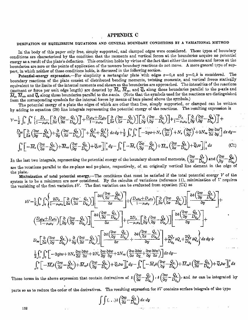
In the body of this paper only free, simply supported, and clamped edges were considered, These typos of boundaryconditions are characterized by the condition that the moments and verticaI forces at tho boundaries acquire no potcntiaIenergy as a result of the pIate.’sdeflection. This condition hokie by virtue of the fact that either the moments and forces at thebounclarieeare zero or the points of application of the nonzero boundary reactions do not move. A more general type of sup-port, in which neither of these conditions holds, is discussed in the following section,
Potential-energy expression.—For simplicity a rectangular plat&itith edges z= O,a and y= O,b is considered. Theboundary reactions of the plate consist of distributed bending moments, twisting moments, and verticaI forces statimllyequivalent to the limits of the internal momenta and sheam as the boundaries are approached. Tho intensitiesof the reactions(moment or force per unit edge Icngth) .gre de,noted by ~,, ~zv, and”~t akmg those boundaries parallel h the y-axis and~~, ~~”, and ??” aIong those boundaries parallel to the x-axis. (Note that the symbols used for the reactions arc distinguishedfrom the corresponding symbols for the internal forces by means of bars pIaced above the symbols.)
The potential energy of a plate the edges of which are other than free, simply supported, or clamped can be writtenby adding to equation (28) line integrals.representkg the potential energy of the reactio~. The resuIting expr-iol~ is
.
(cl)
In the last two integds, representing the potential energy of the boundary shears and moments, ($!i!i-Z?&n&%)are the rotations parallel to the xz-phme and gz-plane, respectively, of. an originally vertical line element in the edge ~fthe plate.. ----
Minimization of total potential energy.—The conditions that must be satisfied if the totaI potentird energy V of llmsystem is to be a minimw are no~vco~idered. By the calculus of variations (reference 11), minimization of V requiresth~ vanishing of the first variation 6V. The first variation can be evaluated from equation (Cl) as
(w-Q=)’’(%-$:)Those terms in the above exprwsion that contain d~iva!ives Of ~ ax Z, , and sw can be integrated by
parte so as to reduce the order of the derivatives. The resulting expression for 31” contains surface integrab of the type
152
A GENERAL SMUIJ-DEWU3CTIONTHEORY FOR FLAT SANDWICH PLATES .---- ..L53
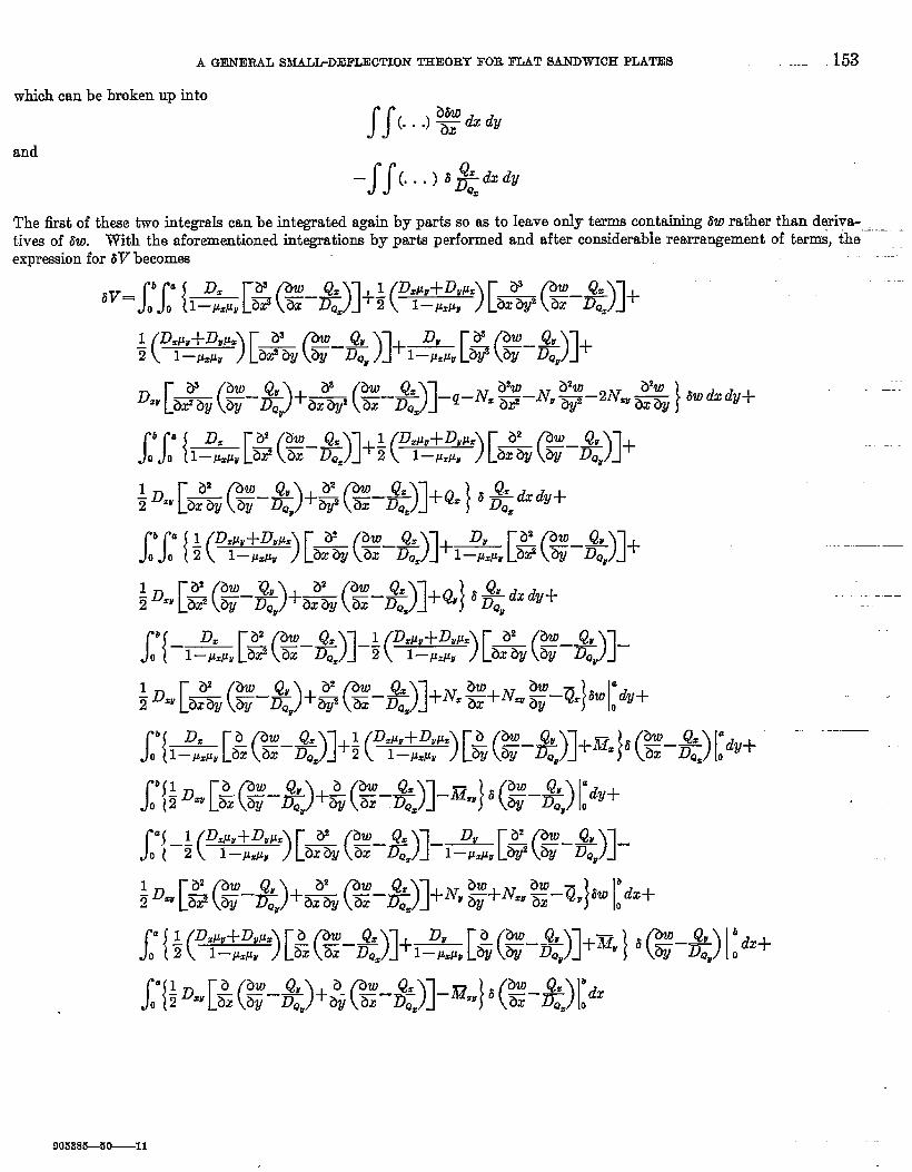
which can be broken up into
SS(...)2&%dfand
—SS(...)tgyzdyThe fist of these two integrde can be integrated again by parts so ss to Ieave O~Y tm~ contti ~W~thertiand~i-t.ivesof tiw. TWth the aforementioned integrations by pafi p~ormed and aft= co~ide~ble rea~a%emcnt of ter~, ~he ~
.—...—
expression for 6V becomes
‘v=rr{l:.P”[~&-%)l+~ fi~:&)[&&-&)l+
-.
( 1-W, )[&(%%)l+*r[%G-%jl+1 D.PU+D~PZ~
D-[&(%-&)+& (#-*)1-’-~= T-’’2~”%2~”% w“’”+
-.
-.
(C2)
(C3)
(C4)
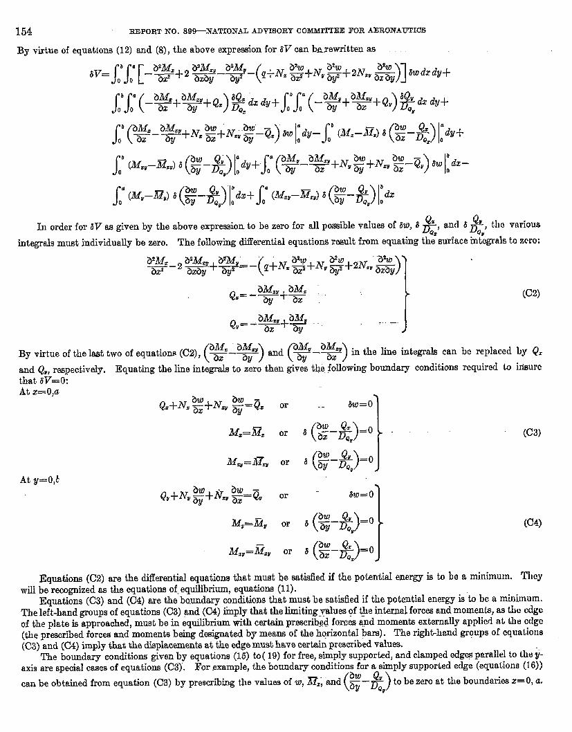
Q. ‘aIn order for 6V as given by the above etiresion to be zero for all p~ible ValUW of aw, ~ ~,, and ~ ~F) tluJ various
integrals must individually be zero. The following differential equations rwndt from equating the surface integrals to zero:
a2A4z__2 ~.+@+=–(“”
?Yw _“Z%
ad )qi-N. ~%~v ~~2NW axay
hMW aM,Q== — ---‘~+ ax
Q,= - i2!&u+~i2#u. . .“.} ‘
By virtue of the last two of equations (C2),~~–~) and~~–g) inthe line integrals can bc replaced by 4?.
and Q, respectively. Equating the line integrals to zero then gives the following boundary conditions required to hieurcthat 8V=O:At x=O,a
QANZ ~+Nz~ @=g. or . tw=o
M==3~= or
-_ .}
‘ (2-%)=0
Mzv=ilTZv or , &@=o
Qv+Nti@i-Nq~=gvor .- 6W=0
Mv=~v or ‘ (%-%)=0
i14,v=Gzv or , ~&&..=(i}
Equations (C2) are the differential equations that must be satisfied if the potentiaI energy is to b~ a minimum. Theywill be recognized as the equations of. equilibrium, equations (11).
Equations (C3) and (C4) are the bmmdary conditions that must be satisfied if the potentia.Ienergy is to bc a minimum.The left-hand groups of equations (C3) and (C4) iinply that the limitingyydues of @e i@ernal forces and moments, as the edgeof the plate is approached, must be in equilibrium with certain prmcrib~d forces and moments externally applied nt th edge(the prescribed forces and moments being designated by means of the horizontal bars). The righ&hancl groups of equations
(C3)and (04) imply that the displacements at the edge must have certain prescribed values.The boundary conditiom given by equations (15) to( 19) for free, simply supported, and clamped edg~ parallel to they-
axi9 are special cases of equations (C3). For example, the boundary conditions for a simply supported eclge (equations (16))
(w-”)can be obtained from equation (C3) by prescrib@g the v~ues of W) ~Z; “~d by ~ to be wo at the boundarn~ x=’~ a“
.4 GENERAL S3L4LL-DIlFLECTIOF7THEORY FOR FLAT SANDWICH PLATES 155 _
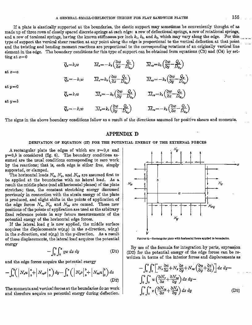
lf a pkde is elastically supported at the boundaries, the elastic support may sometimes be conveniently thought of asmade up of three rows of closely spaced discrete spr@ at each edge: a row of reflectional springs, a row of rotational springs,and a row of torsional springs, having the known st~nesses per inch kl, k~,and kg, which may vary along the edge. For thistype of support the vertical shear reaction at any point along thti edge is proportional to the vertical deflection at that point
-.L-—
and the twisting and bending moment reactions am proportional to the corresponding rotations of an originally vertical line “”–element in the edge. The boundary conditions for this type of support can be obtained from equationa (C3) and (C4) by set-ting at x=O
at x=a
aty=O
The signs in the above boundary conditions follow as a result of the directions assumed for positive shears and moments.
APPENDIX D
DERIVATIONOF EQUATION(27) FOR THE POTENTIALENERGYOF THE EXTERNALFORCES
ii rectangular plate the edges of which are z= O,a andy=O,ZI is considered (fig. 6). The boundary conditions as-sumed are the usual conditions corresponding to zero workby the reactions; that is, each edge is either free, simplysupported, or chtmped.
The horizontal loads N=, iVr, and N,r are assumed first tobe applied at the boundaries with no lateral load. As aresult the middle plane (and all horizontal planes) of the platestretches; thus, the constant stretching energy discuwwlpreciously in connection with the strain energy of the plateis produced, and alight shifts in the points of application ofthe edge forces i%, iVV, and N= are cau%d. These newpositions of the points of application are used as the arbitraryfixed reference points in any future measurements of thepotential energy of the horizontal edge forces.
If the Iateral load q is now applied, the middle surfaceacquires the displacementa u&y) in the z-direction, u(r,y)in the direction, and o(r,y) in the y-direction. As a resultof these displacements, the lateral load acquires the potentialenergy
SSba—
00~W dx dy (Dl)
and the edge forces acquire the potential energy
(D2)
The momenta and vertical forces at the boundaries do no workand therefore acquire no potential energy during deflection.
.$’A i v A J,
~-
r *X
. I +
~ Ib
N=~
iv?. I *
1 <
a >4 f b
L- —- —-— ‘Yx~
1 1 r 1NY
rv
FIC+FBE 13-Recku@uWh tithhti~ for= smiled to boundark
By use of the formula for integration by parts, expression(D2) for the potential ener~ of the edge forces can be re-written in terms of the interior fore= and displacements as
‘ N.2+~’,%+~~(%+2)ld’d’- -m~’jjf!?!+~p,.SS (
baas (h dy~P&v+ti
)(D3)
00
156 REPORT NCJ: 89~NATIONAL ADVISORY .COMiWM?EE FOR AERONAUTICS
In tho development of the differential equations and in thismction the middle+urface stresses N%, iVW,and N& are as-sumed to remain .unc.hanged in the course of the plate’sdeffection. Equations (10) for equilibrium of horizontalforce, consequently, remain satisfied at aIl times, and, there-fore, the last two integmdsof expression (D3) vanish. Further-more, the assumption that the middle-surface stressesremainunchanged implim that no stretching of the middIe surfaceduring deflection occurs. In order to prevent such stretch-ing the horizontal displacements u and o can be. showu(p. 313, reference 6) to be ralated to the ver&al displace-.rnents w as follows:
The first and only remaining integraltherefore becomes ~~
of exprwion (D3)
~ ~] dx dy (D4)
Addition of expressions (Dl) and (D4) gives, as the totalpotential energy of the external force9,
(D5)
Although the derivation was oarried out for the specialcase of a rectangular plate, equation (D5) also applies to a
plate of any shape in which the middle-surface stressesremain unchanged during deflection. Equation (D 5) isidentical with equation (27).
1.
2.
3.
4.
5.
0.
7.
8.
9.
1!3.
11.
REFERENCES
Reissner, Erie: The Effect of Transverse Shear Deformation on theB6iiiing of Elastic Plates. Jour. Appl. Mcch,, vol. 12, no. 2,June 1945, pp. A-69—A-77.
March, H. W.: 13uckling of Flat Plywood Piatcs in Compression,Shesr, or Combined Compression and Shear. Mirnco. h’o. 131fi,Forest Products Lab., U. S. Dept.. Agrlc., April 1942.
March, H, W., and Smith, C, B.: Buckfing Lmds of I?fat SandwichPanels in Compression. Various Types of Edge Conditions.Mimeo. No. 1525, Forest Products Lab., U. S. Dept. Agrio.,March 1945..
Timoshenko, S,: Theory of Plates and Shells. McGraw-Hill BookCo., Inc., 1940, pp. 188-194.
Timoshenko, S.: Theory of Elastic Stabfity. McGraw-EIill BookCo., Inc., 1936.
ReisSBer, Erie: Ou Bending of Elastic Plates. Quarterly Appl.Math., vol. V, no. 1, April 1947, pp. 55-68.
March, H. W.: Buckling Loads of Panels Having Light Coma andD.&ha6“Faces. Mimeo. No. 1504, Fored Products Lab., US.Dept. Agric., Feb. 1944.
Timoshenko, S.: Strength of Materials. part I—Elcmcnf aryTheory and Problems. Second cd., D. Van Nostrand Co., he.,1940.
l?ilonj L. N. G.: On an Approximate Wution for the Btiing of aBeam of Rectangular Crose-Scotion under Any System of Load,with Special Reference to Points of Concentrated or lXscoritiuu-ous Loading. l?hiL Trans. Roy. Sot. (LondonY, ser. A, vol. 201,Aug. 1903, pp. 82-84.
Love; A. E. H.: A Treatise on the Mathematical Theory of Elas-ticity. Fourth cd., Dover Publications, 1944, pp. 173-174.
Woods, Frederick S.: Advanced Calculus. Ginn and Co., 1034,pp. 317-331.