Embed Size (px)
Citation preview
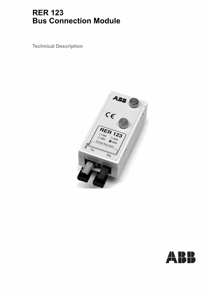
RER 123Bus Connection Module
Technical Description


RER 123 Technical Description
Bus ConnectionModule
1MRS751143-MUM
Issued: 06.11.1998Version: E/08.07.2005
1. About this manual .....................................................................41.1. Copyrights .....................................................................................41.2. Trademarks ...................................................................................41.3. Guarantee .....................................................................................4
2. Safety information .....................................................................53. General .......................................................................................64. Principle of operation ...............................................................75. Construction and mounting .....................................................86. Type designation .....................................................................107. Fibre-optic connectors and technical data ...........................11
©Copyright 2005 ABB Oy, Distribution Automation, Vaasa, FINLAND 3

1MRS751143-MUMRER 123 Technical Description
Bus Connection Module
1. About this manual
1.1. CopyrightsThe information in this document is subject to change without notice and should not be construed as a commitment by ABB Oy. ABB Oy assumes no responsibility for any errors that may appear in this document.
In no event shall ABB Oy be liable for direct, indirect, special, incidental or consequential damages of any nature or kind arising from the use of this document, nor shall ABB Oy be liable for incidental or consequential damages arising from use of any software or hardware described in this document.
This document and parts thereof must not be reproduced or copied without written permission from ABB Oy, and the contents thereof must not be imparted to a third party nor used for any unauthorized purpose.
The software or hardware described in this document is furnished under a license and may be used, copied, or disclosed only in accordance with the terms of such license.
Copyright © 2005 ABB Oy All rights reserved.
1.2. TrademarksABB is a registered trademark of ABB Group.All other brand or product names mentioned in this document may be trademarks or registered trademarks of their respective holders.
1.3. GuaranteePlease inquire about the terms of guarantee from your nearest ABB representative.
4

1MRS751143-MUM Bus ConnectionModule
RER 123 Technical Description
2. Safety information
Dangerous voltages can occur on the connectors, even though the auxiliary voltage has been disconnected.National and local electrical safety regulations must always be followed.The device contains components which are sensitive to electrostatic discharge. Unnecessary touching of electronic components must therefore be avoided.Only a competent electrician is allowed to carry out the electrical installation.Non-observance can result in death, personal injury or substantial property damage.
5

1MRS751143-MUMRER 123 Technical Description
Bus Connection Module
3. General
The bus connection module RER 123 acts as an interfacing unit between an RE_ 54_ device and a fibre-optic SPA, DNP 3.0, Modbus or IEC 60870-5-103 bus. The bus connection module converts incoming optical signals from the bus to electrical RS-232 signals for the RE_ 54_ devices and vice versa. The RER 123 module is connected to a host device with a 9-pin D-type RS-232 connector on the rear plate of the RE_ 54_ device via a cable delivered with the module. It can be used together with any RE_ 54_ device provided with a 9-pin D-type RS-232 connector. The bus connection module is also powered from the same D-type connector of the RE_ 54_ device.
The RER 123 box includes a bus connection module (RER 123), a connection cable, two jumpers, and an installation plate.
The RS-232 interface of the bus connection module RER 123 is shown in the figure below.
A050298A050299
Fig. 3.-1 9-pin D-type connector and block diagram.
�
�
�
�
������� ���� �����������
��� �����
� ��������������������� �� ��� ������ � !"� �������������#���$$ �������������#����% ����� ����
�����
�� ��
������
�� ���������
6
1MRS751143-MUM Bus ConnectionModule
RER 123 Technical Description
4. Principle of operation
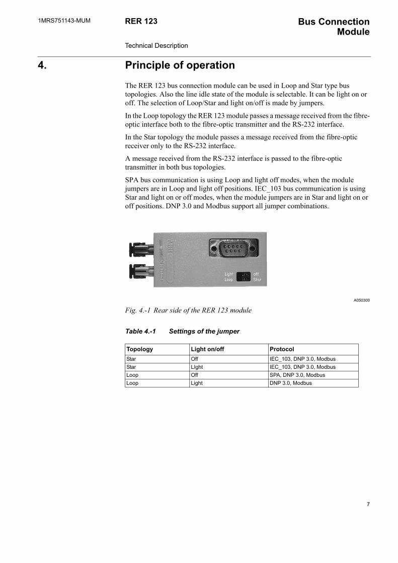
The RER 123 bus connection module can be used in Loop and Star type bus topologies. Also the line idle state of the module is selectable. It can be light on or off. The selection of Loop/Star and light on/off is made by jumpers.
In the Loop topology the RER 123 module passes a message received from the fibre-optic interface both to the fibre-optic transmitter and the RS-232 interface.
In the Star topology the module passes a message received from the fibre-optic receiver only to the RS-232 interface.
A message received from the RS-232 interface is passed to the fibre-optic transmitter in both bus topologies.
SPA bus communication is using Loop and light off modes, when the module jumpers are in Loop and light off positions. IEC_103 bus communication is using Star and light on or off modes, when the module jumpers are in Star and light on or off positions. DNP 3.0 and Modbus support all jumper combinations.
A050300
Fig. 4.-1 Rear side of the RER 123 module
Table 4.-1 Settings of the jumper
Topology Light on/off ProtocolStar Off IEC_103, DNP 3.0, ModbusStar LIght IEC_103, DNP 3.0, ModbusLoop Off SPA, DNP 3.0, ModbusLoop Light DNP 3.0, Modbus
7

1MRS751143-MUMRER 123 Technical Description
Bus Connection Module
5. Construction and mounting
The RER 123 consists of a printed circuit board and is housed in a plastic case. It can be mounted on the rear side of the RE_ 500 device by using the mounting plate and cable delivered with the module. See Figure 5.-2.
A050301
Fig. 5.-1 Dimensional drawing of the bus connection module RER 123
A050302
Fig. 5.-2 Mounting of the RER 123
��������
����
8

1MRS751143-MUM Bus ConnectionModule
RER 123 Technical Description
Connect the cable between the device and the bus connection module and lock it by tightening the finger screws in both ends. To meet the specified EMC requirements, only the connection cable (1MRS120524) delivered with the module may be used between the RER 123 and the device. The incoming optical fibre is connected to the receiver input Rx and the outgoing optical fibre to the transmitter output Tx. Special attention must be paid to the handling, mounting, connection, etc. of optical fibres.
The RER 123 can be provided with connectors for two plastic fibre cables, two glass fibre cables or one of each type. For additional information, refer to the manual �Plastic-core fibre-optic cables. Features and instructions for mounting� (34 SPA 13 EN1).
9

1MRS751143-MUMRER 123 Technical Description
Bus Connection Module
6. Type designation
The IEC star-coupler RER 125 supports only glass-glass and plastic-plastic transceiver connections.
A050303
Type designation Transmitter Receiver Ordering numberRER 123 Plastic Plastic RER123-BBRER 123 Plastic Glass RER123-BMRER 123 Glass Plastic RER123-MBRER 123 Glass Glass RER123-MM
����� ��
���������������� � ����������������� � ��������������
����������������� � ����������������� � ��������������
10

1MRS751143-MUM Bus ConnectionModule
RER 123 Technical Description
7. Fibre-optic connectors and technical data
Table 7.-1 Fibre-optic connectors
Glass fibre Plastic fibreCable connector ST connector snap-in connectorCable diameter 62.5/125 um 1 mmMax. cable length 1000 m 20 mWavelength 820-900 nm 660 nmTransmitted power -13 dBm (HFBR-1414) -13 dBm (HFBR-1521)
Table 7.-2 Technical data
Auxiliary power supply Powered from a host device (9/15 V DC)
Burden ~ 1.2 W
Max. data transfer rate 19.2 kbps
Mechanical dimensions RER 123 Width: 35.0 mm
Height: 73.0 mm
Depth: 20.0 mm
RER 123 with RE_ 54_
Width: 25 cm
Connection cable 1MRS120524
Length: 350.0 mm
Operating temperature range -10�55 oC
Storage temperature range -40�70 oC
11

ABB OyDistribution Automation P.O. Box 699FI-65101 VaasaFINLANDTel. +358 10 22 11Fax. +358 10 224 1094www.abb.com/substationautomation
1MR
S75
1143
-MU
M E
N 0
7.20
05