Embed Size (px)
Citation preview
Hindawi Publishing CorporationISRNThermodynamicsVolume 2013, Article ID 253437, 4 pageshttp://dx.doi.org/10.1155/2013/253437
Research ArticleA New Cryogenic Air Separation Process with Flash Separator
Zeinab A. M. Khalel, Ali A. Rabah, and Taj Alasfia M. Barakat
Department of Chemical Engineering, Faculty of Engineering, University of Khartoum, P.O. Box 321, Khartoum 11111, Sudan
Correspondence should be addressed to Ali A. Rabah; [email protected]
Received 15 May 2013; Accepted 13 June 2013
Academic Editors: R. R. Burnette, T. Chen, P. Espeau, and P. Trens
Copyright © 2013 Zeinab A. M. Khalel et al. This is an open access article distributed under the Creative Commons AttributionLicense, which permits unrestricted use, distribution, and reproduction in any medium, provided the original work is properlycited.
A new cryogenic air separation process with flash separator is developed. A flash separator is added to the conventional double-column cryogenic air separation process. The flash separator is used to replace the turbine required to recover a portion of theenergy in the double-column air separation process. The flash separator served dual purposes of throttling and separation. Boththe conventional and the new processes are simulated using Aspen Plus version 11.1 the model air flow rate and compositions aretaken as 50000Nm3/h of air at standard conditions of 1 atm and 25∘C and feed composition of 79.1% N
2and 20.9% O
2. The new
process decreases the energy consumption and increases the productivity.
1. Introduction
There are mainly three methods of air separation, cryogenicdistillation, pressure swing absorption, and membrane sepa-ration. Although the latter two methods have become morecompetitive, cryogenic distillation remained the dominantchoice for mass production of high-purity O
2. The first
cryogenic distillation unit with single-column was built in1902 and shortly followed by double-column process. Thedouble column consists of compressors, low- and high-pressure columns, and two sets of heat exchangers. The low-and high-pressure columns are thermally interconnected[1].
Although the double-column process is widely used, itshigh energy consumption remains challenging. Therefore inthe recent past, the double column has been subjected tomany energy-efficient modifications such as changing theoperation condition of the low-pressure column from low tomoderate pressure [2]. This modification resulted in smallersize of the column and 10% energy savings. The modificationhas also the advantage of argon recovery (up to 5% greaterargon recovery over the conventional). Anothermodificationis the addition of a heat pump to a side rectifier which is ther-mally linked to the two columns. The heat pump enhancesthe separation by providing a supplementary crude argoncondensing duty [3]. Reference [4] did an exergy analysis ofthe double-column air separation process. It found that more
than half of the exergy loss takes place in the liquefactionunit and almost one-third in the air compression unit, andminor exergy losses are taking place in the distillation unitand the main heat exchangers. Reference [5] has changed thedesign of the double column to single column using self-heatrecuperation technology (i.e., heat from the top vapor streamis recuperated and exchanged with heat in the bottom liquidand feed streams). The author’s modifications have improvedthe energy consumption by around 36% of the conventionalprocess.
This work is aimed to develop an energy-efficient airseparation process. Flash separator has the advantage ofworking as throttling device on one hand and vapor liquidseparation unit on the other hand. It is introduced into theconventional double-columnair separation process to replacethe turbine needed to expand the air prior to injection tolower-pressure distillation column.
2. Process Description
Figure 1 shows schematic presentation of the conventionaldouble-column cryogenic air separation process. It consistsof two compressors (C1 and C2), a turbine (T), two thermallylinked distillation columns (low-pressure column (LPC) andhigh-pressure column (HPC)), and two sets of heat exchang-ers (HX1, HX2). The air is compressed from atmosphericpressure to 6 atm in C1. The compressed air is then split into
2 ISRNThermodynamics
AirHX1 HX2
LPC
HPC
T
C1C2
O2
N2
Waste N2
Figure 1: Conventional double-column cryogenic air separationprocess.
two streams; one stream for HPC (hereafter is called HPCsplit) and the other stream for LPC (hereafter is called LPCsplit). The LPC split is compressed in C2 further to 7.5 atm,cooled in HX1, throttled in T to 1.3 atm, and finally fed toLPC. The HPC split is cooled in HX1 and then fed to HPC.The products of LPC are pure N
2(top), pure O
2(bottom),
and waste N2(side stream). The products of HPC are pure
N2(top) and air-enriched oxygen (bottom). The pure N
2of
HPC is working as reflux to the LPC and the air-enrichedoxygen of HPC is an extra feed to the LPC.The two columnsare thus thermally linked by exchanging the latent heat ofvaporization via condenser of the HPC and reboiler of theLPC. The products of the LPC are liquid pure oxygen fromthe bottom, gas pure nitrogen from the top, and side productof waste nitrogen; all these products are heated in the two setsof heat exchangers prior to be sent as final products.
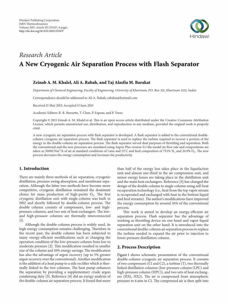
Figure 2 shows schematic presentation of the new cryo-genic air separation process with flash separator. The air iscompressed inC3 from atmospheric pressure to 4 atm insteadof 6 atm as in the conventional process then split into twostreams. The HPC split is compressed in C4 further to 6 atmand subsequently cooled in HX1 and then injected to HPC.Hence this stream is maintained at the same conditions asthese in the conventional process. The LPC split is cooled inHX1 and then throttled in a flash separator (F) to 1.3 atm.Thebottom product of the flash separator is air-enriched O
2and
the top product is a waste N2. The waste N
2is a final product
(mixed with the waste nitrogen from the LPC). The bottomproduct of the flash (air-riched O
2) is fed to the LPC. The
rest of the process remains the same as in the conventionalprocess.
Clearly the flash separator replaces the turbine of theconventional double column. Although the turbine is used torecover part of the work introduced into the compressors, theother point to be noticed in this new design is that the LPCsplit is compressed to 4 atm only rather than 7.5 atm as in theconventional process.
3. Simulation
Both the conventional and the new cryogenic air separationprocesses are simulated using Aspen Plus version 11.1 with thePeng-Robinson equation of state as a fluid package [6].
Table 1: Model air specification.
Parameter Value UnitFlow rate 50000 Nm3/hPressure 1 atmTemperature 298 ∘KN2 79.1 Mole %O2 20.9 Mole %
Table 2: Design and operating conditions of distillation columns.
Parameter ColumnLPC HPC
No. of stages 20 15Reboiler duty 2141 kW —Condenser duty — 2146 kW
The following assumptions are considered in this work.
(1) The model air is assumed to gain 5K in the processesof drying and cleaning prior to the inlet of the maincompressor.
(2) The pressure drop across the heat exchangers is takenas 0.1 atm.
(3) The pressure drop along the HPC and the LPC is0.1 atm.
(4) The minimum temperature approach is 1.5 K for theHX1 and 2.5 K for HX2.
(5) 5 kW is lost during the thermal integration betweenthe two columns.
The model air flow rate and composition are shown inTable 1.
The compressors C1, C3, and C4 are simulated as mul-tistage compressors (two stages), while C2 is simulated assingle stage because the pressure difference is only 1.5 atm.The cooling duty for multistage compressor is neglected ascooling water is assumed to be taken from large reservoirlike the electrical energy consumed in pumps. The pumpsare considered as auxiliary devices and common in bothconventional and new processes. The distillation columns inboth processes are simulated by a block known as RadFrac.The two sets of heat exchangers (HX1, HX2) are simulated byblock called MHeatX.
4. Results and Discussion
The core of any cryogenic air separation process is distillationunit; here and asmentioned before theHPC split specificationremains the same in the conventional and new processes, sothe value of the condenser duty of the HPC from the firstrun is input as the value of the reboiler duty of the LPC.These values are shown in Table 2. Also the number of stagesof the HPC and the LPC is adjusted using the compositionprofile; the number of stages is taken when there is no muchdifference in the product purities with the increased numberof states; the number of stages is given in Table 2.
ISRNThermodynamics 3
Table 3: Specification of product streams.
Product Conventional process New processFlow rate O2 N2 Flow rate O2 N2
O2 (g) 8038 99.99 0.01 9189 99.98 0.02N2 (g) 10602 0.13 99.87 11178 0.13 99.87Waste N2 (g) 31360 7.65 92.35 29633 4.21 95.79
The flow rate in Nm3/h and composition in mole %
Table 4: Specification of energy consumption units.
BlockConventional process New process
Pressure (atm) Work (kW) Pressure (atm) Work (kW)In Out In Out
C1 1 6 4390 — — —C2 6 7.5 79 — — —C3 — — — 1 4 3296C4 — — — 4 6 748Turbine/flash 7.4 1.3 −81 3.9 1.3 —Net energy consumption 4388 kW 4044 kWSpecific energy consumption 0.55 kW⋅h/Nm3 O2 0.44 kW⋅h/Nm3 O2
F
AirHX1 HX2
LPC
HPC
C3C4
O2
N2
Waste N2
Figure 2: New cryogenic air separation process with flash separator.
Table 3 shows the simulation result of products flow ratesand composition. It can be seen that there is no significantdifference in the product purity of both process, but in thenew process there is an increase in the flow rate of oxygen by14.3% and nitrogen by 5.4%, while the flow rate of the wastenitrogen (undesirable product) decreased by 5.5%.
This is attributed to the change in LPC feed. In thenew process the feed to LPC is reduced by the early sep-aration of the waste N
2in the flash separator. Hence the
feed is less in quantity and enrich in O2than that in the
conventional process. This change in the feed quantity andcomposition is expected to have either influence on the LPCunit specification or the quality of the product. Since theLPC column specifications are maintained similar to those inthe conventional process, the feed change is reflected in theproducts quantity.
Also it is important to mention that in the conventionalprocess the outlet pressure of C2 controlled the pressure drop
(Pa)
Mol
e (%
)
3000
00
3200
00
3400
00
3600
00
3800
00
4000
00
4200
00
4400
00
0.8
0.85
0.9
0.95
1
O2
Figure 3: The outlet pressure of C3 versus product oxygen purity.
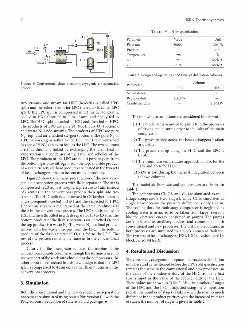
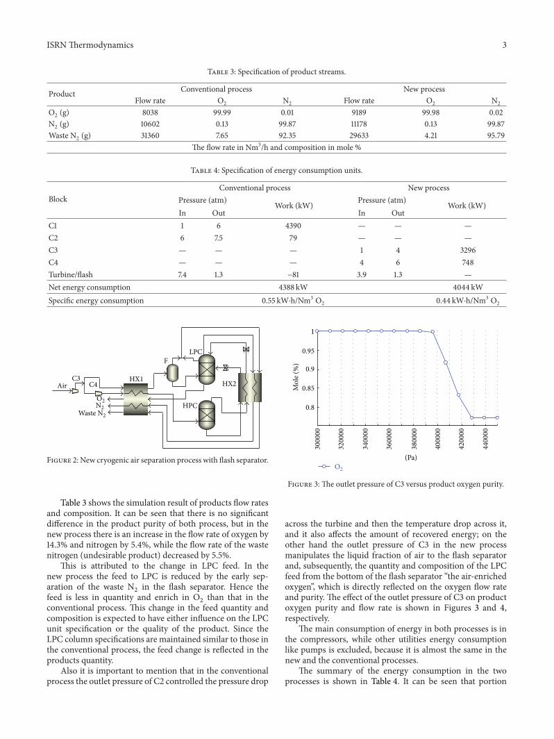
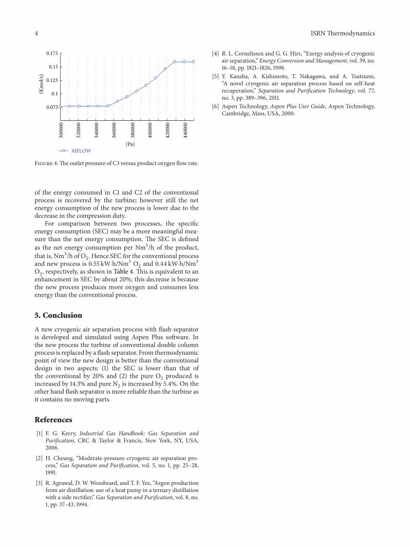
across the turbine and then the temperature drop across it,and it also affects the amount of recovered energy; on theother hand the outlet pressure of C3 in the new processmanipulates the liquid fraction of air to the flash separatorand, subsequently, the quantity and composition of the LPCfeed from the bottom of the flash separator “the air-enrichedoxygen”, which is directly reflected on the oxygen flow rateand purity. The effect of the outlet pressure of C3 on productoxygen purity and flow rate is shown in Figures 3 and 4,respectively.
The main consumption of energy in both processes is inthe compressors, while other utilities energy consumptionlike pumps is excluded, because it is almost the same in thenew and the conventional processes.
The summary of the energy consumption in the twoprocesses is shown in Table 4. It can be seen that portion
4 ISRNThermodynamics(K
mol
/s)
0.075
0.1
0.125
0.15
0.175
MFLOW (Pa)
3000
00
3200
00
3400
00
3600
00
3800
00
4000
00
4200
00
4400
00
Figure 4:The outlet pressure of C3 versus product oxygen flow rate.
of the energy consumed in C1 and C2 of the conventionalprocess is recovered by the turbine; however still the netenergy consumption of the new process is lower due to thedecrease in the compression duty.
For comparison between two processes, the specificenergy consumption (SEC) may be a more meaningful mea-sure than the net energy consumption. The SEC is definedas the net energy consumption per Nm3/h of the product,that is, Nm3/h of O
2. Hence SEC for the conventional process
and new process is 0.55 kW⋅h/Nm3 O2and 0.44 kW⋅h/Nm3
O2, respectively, as shown in Table 4. This is equivalent to an
enhancement in SEC by about 20%; this decrease is becausethe new process produces more oxygen and consumes lessenergy than the conventional process.
5. Conclusion
A new cryogenic air separation process with flash separatoris developed and simulated using Aspen Plus software. Inthe new process the turbine of conventional double columnprocess is replaced by a flash separator. From thermodynamicpoint of view the new design is better than the conventionaldesign in two aspects: (1) the SEC is lower than that ofthe conventional by 20% and (2) the pure O
2produced is
increased by 14.3% and pure N2is increased by 5.4%. On the
other hand flash separator is more reliable than the turbine asit contains no moving parts.
References
[1] F. G. Kerry, Industrial Gas Handbook: Gas Separation andPurification, CRC & Taylor & Francis, New York, NY, USA,2006.
[2] H. Cheung, “Moderate-pressure cryogenic air separation pro-cess,” Gas Separation and Purification, vol. 5, no. 1, pp. 25–28,1991.
[3] R. Agrawal, D. W. Woodward, and T. F. Yee, “Argon productionfrom air distillation: use of a heat pump in a ternary distillationwith a side rectifier,” Gas Separation and Purification, vol. 8, no.1, pp. 37–43, 1994.
[4] R. L. Cornelissen and G. G. Hirs, “Exergy analysis of cryogenicair separation,” Energy Conversion andManagement, vol. 39, no.16–18, pp. 1821–1826, 1998.
[5] Y. Kansha, A. Kishimoto, T. Nakagawa, and A. Tsutsumi,“A novel cryogenic air separation process based on self-heatrecuperation,” Separation and Purification Technology, vol. 77,no. 3, pp. 389–396, 2011.
[6] Aspen Technology, Aspen Plus User Guide, Aspen Technology,Cambridge, Mass, USA, 2000.

Submit your manuscripts athttp://www.hindawi.com
Hindawi Publishing Corporationhttp://www.hindawi.com Volume 2014
High Energy PhysicsAdvances in
The Scientific World JournalHindawi Publishing Corporation http://www.hindawi.com Volume 2014
Hindawi Publishing Corporationhttp://www.hindawi.com Volume 2014
FluidsJournal of
Atomic and Molecular Physics
Journal of
Hindawi Publishing Corporationhttp://www.hindawi.com Volume 2014
Hindawi Publishing Corporationhttp://www.hindawi.com Volume 2014
Advances in Condensed Matter Physics
OpticsInternational Journal of
Hindawi Publishing Corporationhttp://www.hindawi.com Volume 2014
Hindawi Publishing Corporationhttp://www.hindawi.com Volume 2014
AstronomyAdvances in
International Journal of
Hindawi Publishing Corporationhttp://www.hindawi.com Volume 2014
Superconductivity
Hindawi Publishing Corporationhttp://www.hindawi.com Volume 2014
Statistical MechanicsInternational Journal of
Hindawi Publishing Corporationhttp://www.hindawi.com Volume 2014
GravityJournal of
Hindawi Publishing Corporationhttp://www.hindawi.com Volume 2014
AstrophysicsJournal of
Hindawi Publishing Corporationhttp://www.hindawi.com Volume 2014
Physics Research International
Hindawi Publishing Corporationhttp://www.hindawi.com Volume 2014
Solid State PhysicsJournal of
Computational Methods in Physics
Journal of
Hindawi Publishing Corporationhttp://www.hindawi.com Volume 2014
Hindawi Publishing Corporationhttp://www.hindawi.com Volume 2014
Soft MatterJournal of
Hindawi Publishing Corporationhttp://www.hindawi.com
AerodynamicsJournal of
Volume 2014
Hindawi Publishing Corporationhttp://www.hindawi.com Volume 2014
PhotonicsJournal of
Hindawi Publishing Corporationhttp://www.hindawi.com Volume 2014
Journal of
Biophysics
Hindawi Publishing Corporationhttp://www.hindawi.com Volume 2014
ThermodynamicsJournal of