Embed Size (px)
Citation preview

Department of Mechanical Engineering
Thermal Engineering Lab
1

EXPERIMENT NO: 1VALVE TIMING DIAGRAMS OF I.C. ENGINES
AIM: To draw the valve timing diagram of the four stroke cycle diesel
engine.
APPARATUS: i) Four stroke cycle diesel engineii) Measuring tapeiii) Chuckiv) Piece of paper
THEORY:-The diagram which shows the position of chuck of four stroke cycle
engine at the beginning and at the end of suction, compression and expansion and exhaust of the engine are called as valve timing diagram.
The extreme position of the piston at the bottom of the cylinder is called bottom dead centre (BDC) in the case of centre (ODC) the extreme position of the piston at the top of the cylinder is called top dead centre (TDC) in the case of horizontal engine this is known as inner dead centre (IDC).
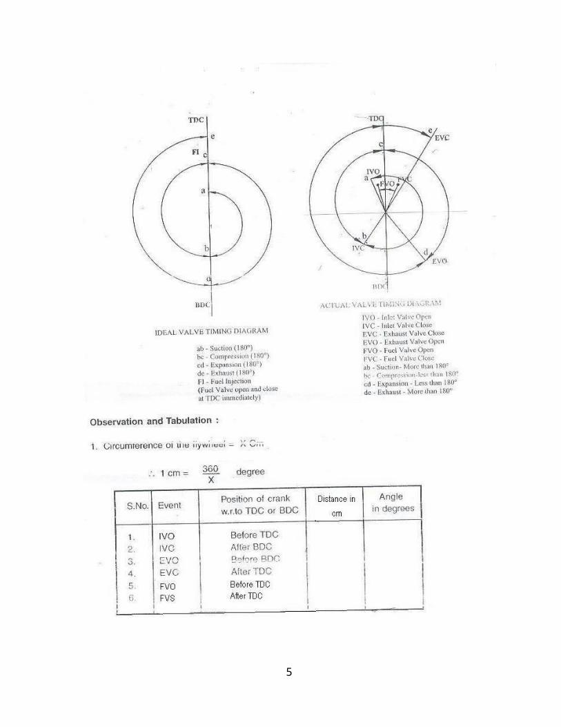
In an ideal engine the inlet valve open at TDC and closed at BDC. The exhaust valve opens at BDC and closes at TDC the fuel is injected in to the cylinder when the position is at TDC and at the end of the compression stroke but in actual practice it will differ.Inlet Valve opening and closing:
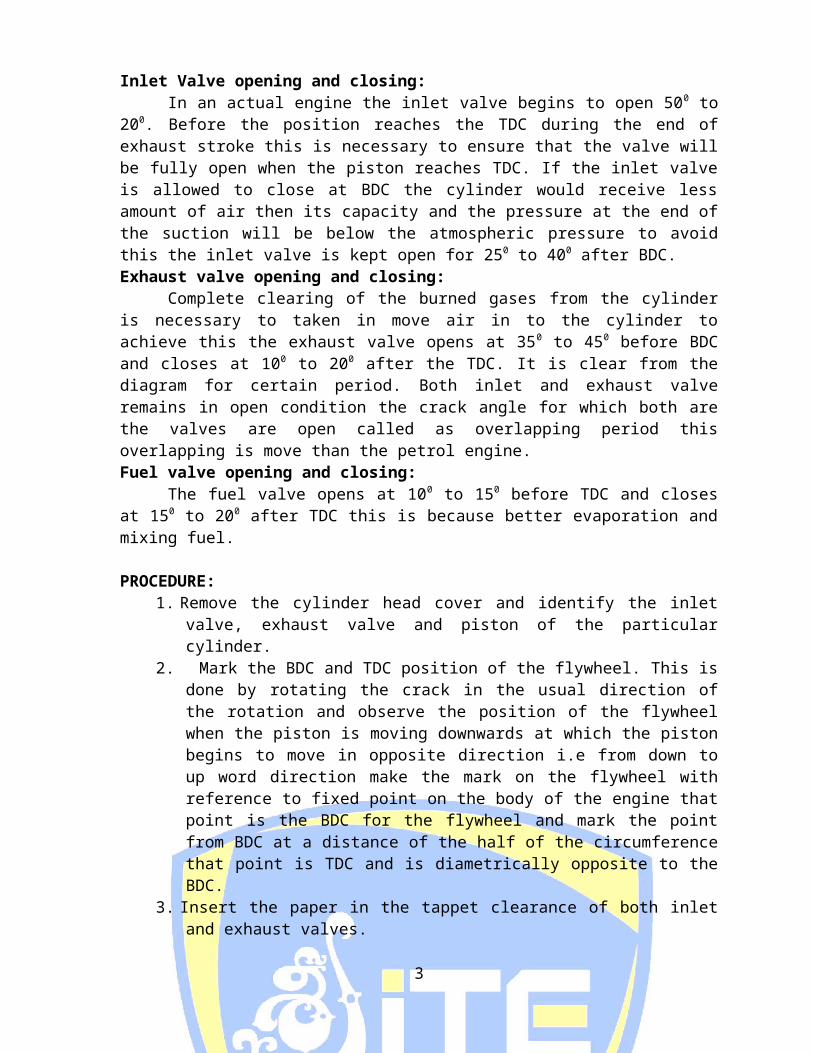
In an actual engine the inlet valve begins to open 500 to 200. Before the position reaches the TDC during the end of exhaust stroke this is necessary to ensure that the valve will be fully open when the piston reaches TDC. If the inlet valve is allowed to close at BDC the cylinder would receive less amount of air then its capacity and the pressure at the end of the suction will be below the atmospheric pressure to avoid this the inlet valve is kept open for 250 to 400 after BDC. Exhaust valve opening and closing: Complete clearing of the burned gases from the cylinder is necessary to taken in move air in to the cylinder to achieve this the exhaust valve opens at 350 to 450 before BDC and closes at 100 to 200
after the TDC. It is clear from the diagram for certain period. Both inlet and exhaust valve remains in open condition the crack angle for which both are the valves are open called as overlapping period this overlapping is move than the petrol engine. Fuel valve opening and closing:
The fuel valve opens at 100 to 150 before TDC and closes at 150 to 200 after TDC this is because better evaporation and mixing fuel.
PROCEDURE: 1. Remove the cylinder head cover and identify the inlet valve,
exhaust valve and piston of the particular cylinder.
2
2. Mark the BDC and TDC position of the flywheel. This is done by rotating the crack in the usual direction of the rotation and observe the position of the flywheel when the piston is moving downwards at which the piston begins to move in opposite direction i.e from down to up word direction make the mark on the flywheel with reference to fixed point on the body of the engine that point is the BDC for the flywheel and mark the point from BDC at a distance of the half of the circumference that point is TDC and is diametrically opposite to the BDC.
3. Insert the paper in the tappet clearance of both inlet and exhaust valves.
4. Slowly rotate the crank until the paper in the tappet clearance of the inlet valve is gripped make the mark on flywheel against fixed reference this position represents the inlet valve open (IVO) measure the distance from TDC and tabulated the distance.
5. Rotate the crank further, till the paper is just free to move make the marking on the flywheel against the fixed reference this position represents the inlet valve closing (IVC) measure the distance.
6. Rotate the crank further till the paper in the tappet clearance of the exhaust valve is gripped reference this position represents exhaust valve open (EVO) measure the distance from BDC and tabulated it.
7. Rotate the crank further, till the paper in the tappet clearance of exhaust valve is just free to move make the marking on flywheel against fixed reference this position represents the fixed reference this position represents the exhaust valve close (EVC) measure the distance from TDC and tabulated it
8. Then converted the measure distance in to angle decrease.
FORMULAE USED:- Θ = Length / Circumference x 3600
Observation &Tabulation:-
Sl. No.
Event Position of crank to TDC or BDC Distance in CM
Angle in degree
1 IVO Before TDC2 IVC After BDC3 EVO Before BDC4 EVC After TDC
RESULT:- The valve timing diagram for the given four stroke diesel engine was drawn.
3

4
EXPERIMENT NO: 2
PORT TIMING DIAGRAM OF TWO STROKE CYCLE PERTROL ENGINE Ex.No. : Date: Aim : To draw the port timing diagram of given two stroke cycle petrol engine . Apparatus Required : 1. Two stroke petrol engine 2. Measuring tape 3. Chalk
Theory and Description : In the case of two stroke cycle engines the inlet and exhaust valves
are not present . Instead , the slots are cut on the cylinder itself at different elevation and they are called ports. There are three ports are present in the two stroke cycle engine . 1. Inlet port 2. Transfer port 3. Exhaust port
The diagram which shows the position of crank at which the above ports are open and close are called as port timing diagram.
The extreme position of the piston at the bottom of the cylinder is called “ Bottom Dead centre “ [BDC] . The extreme position of the piston at the top of the cylinder is called “TOP dead centre “ [TDC ]
In two stroke petrol engine the inlet port open when the piston moves from BDC to TDC and is closed when the piston moves from TDC to BDC . The transfer port is opened when the piston is moved from TDC to BDC and the fuel enters into the cylinder through this transport from the crank case of the engine . The transfer port is closed when piston moves from BDC to TDC . The transfer port opening and closing are measured with respect to the BDC .
The exhaust port is opened , when the piston moves from TDC to BDC and is closed when piston moves from BDC to TDC . The exhaust port opening and closing are measured with respect to the BDC.
5
Procedure : 1. Remove the ports cover and identify the three ports . 2. Mark the TDC and BDC position of the fly wheel . To mark this position
follow the same procedure as followed in valve timing diagram . 3. Rotate the flywheel slowly in usual direction (usually clockwise ) and
observe the movement of the piston 4. When the piston moves from BDC to TDC observe when the bottom
edge of the piston . Just uncover the bottom end of the inlet port . This is the inlet port opening (IPO) condition , make the mark on the flywheel and measure the distance from TDC
5. When piston moves from TDC to BDC observe when the bottom edge of the piston completely covers the inlet port . This is the inlet port closing
6

(IPC) condition . Make the mark on the flywheel and measure the distance from TDC .
6. When the piston moves from TDC to BDC , observe , when the top edge of the piston just uncover the exhaust port . This is the exhaust port opening [EPO] condition . Make the mark on the flywheel and measure the distance from BDC .
7. When the piston moves from BDC to TDC , observe , when the piston completely cover the exhaust port ,. This is the exhaust port closing condition [EPC] . Make the mark on the flywheel and measure the distance from BDC . 8. When the piston moves from TDC to BDC observe, when the top edge of the piston just uncover the transfer port . This is the transfer port opening [TPO] condition . Make the mark on the flywheel and measure the distance from BDC 9. When the piston moves from BDC to TDC , observe , when the piston completely covers the transfer port. This is the transfer port closing [TPC] condition . Make the mark on the flywheel and measure the distance from BDC .
Note : 1. The inlet port opening distance and closing distance from TDC are equal . 2. The exhaust port opening distance and closing distance from BDC are equal . 3. The transfer port opening distance and closing distance from BDC are equal . Result :
The port timing diagram for the given two stroke cycle petrol engine was drawn
7

EXPERIMENT NO: 3
PERFORMANCE TEST ON A FOUR STROKE PETROL ENGINE
AIM: To Conduct Performance Test on 4-stroke single cylinder petrol engine and draw performance curves.
APPRATUS REQUIRED:- Four Stroke Engine with electrical loading, Stop watch etc,.
THEORY:-This engine works on 4 strokes which are suction, compression, power and exhaust stroke. Valves are used in this engine to allow and exhaust the working fluids. Using dynamometers can do the performance of the engine. Various types of dynamometers are available, which are rope brake dynamometer, electrical dynamometer, and hydraulic dynamometer.OBSERVATIONS: 1. Cylinder bore D : 70 mm 2. Stroke length L : 66.7 mm
3. Water density ρw : 1000 kg/m3
4. Calorific value of petrol CV : 41,000 Kj/kg5. Acceleration due to gravity g : 9.81 m/sec 2
6. Petrol density ρf : 0.8 Kg/lit7. Air Density ρa : 1.2 Kg/ m3
PROCEDURE:
a. Check all electrical connections and check petrol and oil in the engine.
b. Open valves of 3 way manifold, make fuel flow to engine directlyc. With the help of rope start the engined. Wait until it stabilizes for rated speede. Now take readings of manometer, temperature, Voltage and
currentf. Close valve of 3 way block, now fuel flows to engine from buretteg. Note down time taken for 10 cc of fuelh. Now switch ON first two switches for load.i. Note down readings of fuel Consumption, Volts, Current, and
Temperature.j. Continue loading the engine step by step for different load
condition, by switching on the load switches.k. Tabulate all the readings and calculate brake power, Brake
thermal efficiency, Brake specific fuel consumption and plot the graph Qin v/sBP,SFC v/s BP, b v/s BP.
FORMULAE USED:
8

01. Mass flow rate of Air: Ma in kg/s Ma = Ao x Cd x a x (2 x g x Ha) kg/s
Where : Area of Orifice, Ao = { /4 x do2} m2
do (Orifice diameter) = 20 mm ( 0.02 m) Head of Air, Ha = {(h1 ~ h2) x w} /a m h1 and h2 from manometer in m
a = Air density = 1.2 kg/m3
w = Water density = 1,000 kg/m3
Cd = 0.64 02. Mass of fuel consumed: mf in kg/s mf = [V x f] / [1000 x t] kg/s Where V = fuel consumed in cc (10cc) f = Fuel density = 0.85 kg / lit
t = Time in seconds for 10cc of petrol 03. BRAKE POWER: BP
BP = (V x I) / (1000 x ηg) in kW Where V = Voltage, Volts
I = Current, amps ηg = Generator Efficiency = 0.68
04. HEAT SUPPLIED Qi in kW Qi = mf x C V kW
Where C V is calorific value of the fuel =41,500 kJ/kg05. AIR FUEL RATIO : A/F A/F = ma / mf06. BRAKE THERMAL EFFICIENCY: b in % b = {BP / Qi } x 100 %07. SPECIFIC FUEL CONSUMPTION: SFC
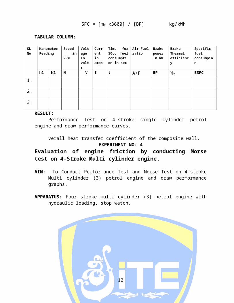
SFC = [mf x3600] / [BP] kg/kWh
TABULAR COLUMN:
RESULT: Performance Test on 4-stroke single cylinder petrol engine and draw
performance curves.
9
SL No
Manometer Reading
Speed in RPM
VoltageIn volts
Current in amps
Time for 10cc fuel consumption in sec
Air-Fuel ratio
Brake powerIn kW
Brake Thermal efficiency
Specific fuel consumpion
h1 h2 N V I t A/F BP b BSFC
1.
2.
3.

verall heat transfer coefficient of the composite wall.EXPERIMENT NO: 4
Evaluation of engine friction by conducting Morse test on 4-Stroke Multi cylinder engine.
AIM: To Conduct Performance Test and Morse Test on 4-stroke Multi cylinder (3) petrol engine and draw performance graphs.
APPARATUS: Four stroke multi cylinder (3) petrol engine with hydraulic loading, stop watch.
THEORY: Indicated power is the power produced inside the cylinder due to burning of the fuel. IP can be obtained by knowing the mean effective pressure or conducting Morse test. Morse test is applicable to multi cylinder petrol or diesel engine. In petrol engine IP can be obtained by knowing the IP of the individual cylinder by cut off the power supply to the spark plug of that cylinder. Friction power (FP) can be calculated after knowing IP and BP of engine when all cylinders are working.
DESCRIPTION OF THE TEST RIG: The engine is four stroke, three cylinder, water cooled petrol driven automobile (Maruti) engine coupled to a hydraulic dynamometer mounted on strong base, and is complete with air, fuel temperature, load and speed measurement system the specifications are
ENGINE: Four stroke three cylinder spark ignited vertical in line water cooled petrol driven engine with Morse test facility.
Make: MarutiCylinders: ThreeStarting: SelfIgnition:Spark
Hydraulic Dynamometer : Type: Water brake Display: Spring Balance
PROCEDURE TO CONDUCT MORSE TEST:a. Start the engine with water flow in to the engine jacket.b. Load the engine to its full load at rated RPM.c. Cut off first cylinder (cylinder 2nd & 3rd are working) the engine
speed drops, bring the engine speed to its rated speed by decreasing the load on the engine (do not operate throttle).
d. Record the test as indicated on the digital load indicator.e. Repeat the procedure of cut off 2nd cylinder (1st & 3rd are working)
and 3rd cylinder (1st & 2nd are working) individually engine has
10

three cylinder ensure always two cylinder are in working condition.
f. Tabulate the reading and calculate BP, IP & FP of the engine using the formulae.
FORMULAE USED FOR MORSE TEST:-
1. Brake power : B.P. = 2πNT60000
N = engine speed in RPMT = Torque = W x R in N/mW = Net load on the engine KgfR = Torque arm length 358.1 mm (0.3581m)
2. Indicated power when first cylinder not working(IP) 1 = B.P – (BP)1Second cylinder is not working(IP)2 = (BP) – (BP)2Third cylinder is not working(IP)3 = (BP) – (BP)3
3. Total indicated power IP = (IP)1 + (IP)2 + (IP)3 kw4. Frictional power f.p = IP – BP kw
Observation and Tabulation : (1) Brake power B.P =........... KW (2) Rated Speed N =...........Rpm (3) Type of loading : =........... (4) Radius of brake drum : R =........... ‘m’ (5) Radius of Rope r = =........... ‘m’ (6) Number of cylinders = 4
Sl No
Conditions Loading Speed RPM
Break Power in KW
W1 Kg
W2Kg
W1 – W2 Kg
Net load W in ‘N’
1 All cylinders are working
2 First cylinder was cut off and remaining are in working
3 Second cylinder was cut off and remaining are in working
4 Third cylinder was cut off and remaining are in working
5 Fourth cylinder was cut off and remaining are in working
11
PROCEDURE TO CONDUCT PERFORMANCE TEST:a. Check all electrical connections water supply and fuel in the tank
and oil level.b. Open valves of three ways fitting make fuel flow to engine
directly.c. Start the engine with self – self ignition key.d. Throttle the engine to the rated speed (2000RPM) without any
load (zero load)e. Now take readings of manometer temperature, and time for 10cc
fuel consumption.f. Repeat the experiment by loading the engine in steps the speed
constant by operating the throttle knob (accelerator) subjected to maintain the speed at 2000 RPM and record manometer difference time for 10cc fuel consumption, load indicated on the digital load indicator and speed of the engine.
g. Calculate BP, IP, mechanical efficiency, brake thermal efficiency, indicated thermal efficiency, specific fuel consumption on IP basis and BP basis.
h. Float the graph Q in V/s B.P, ISFC V/s B.P, BSFC V/s BP, ηth V/s BP, ηith V/s BP plot the graph.
FORMULAE USED FOR PERFORMANCE TEST:-
1. Mass flow rate of air = Ma in Kg / secMa = Ao x Cd x ρa x √(2 x g x Ha) Kg/sWhere : area of orifice; Ao = {π4 do
2} m2
do (orifice diameter) Head of air, Ha = {h1 – h2} ρw / ρa in mh1 and h2 from manometer in mρa = air densityρw = water density
2. Mass of fuel consumed = Mf in Kg/sMf = (V x ρf) / (1000 x t) Kg/sWhere v = fuel consumed in cc (10cc) ρt = fuel density in kg / litt = time in seconds for 10 cc of petrol
3. Head supplied Qi in Kw.Qi = Mf x Cv KwWhere Cv is calorific value of the fuel
4. Break Power (BP) : 2πNT X 9.8160000 Kw
5. Indicated Power (IP)IP = BP + FP in the frictional power obtained from Morse test.
12

6. Mechanical Efficiency = η mech %η mech = (BP / IP) X 100
7. Brake Thermal Efficiency : η bth % η bth % = { Bp / Qi } X 100 %
8. Indicated thermal efficiency : η ith in %η ith = {IP/Qi} X 100%
9. Specific fuel consumption on BP basis = BsfcBsfc = (Mf x 3600) / (BP) kg / kgw hr.
10.Specific fuel consumption on IP basis = ISFCISFC = (Mf x 3600) / (IP) kg / kw hr.
Result: Morse test was conducted on given petrol engine and indicated power
developed in each cylinder is determined and mechanical efficiency is also determined.
13

EXPERIMENT NO: 5
PERFORMANCE TEST ON VARIABLE COMPRESSION RATIO PETROL ENGINE
AIM: To Conduct Performance Test on 4-stroke single cylinder variable compression ratio (VCR) petrol engine for different compression ratios and draw performance curves.
APPRATUS REQUIRED:- 4-Stroke VCR Engine with electrical loading, Stop watch etc,.
THEORY:- Internal combustion engines develop varying brake power depending on the compression ratio, while the other parameters kept constant. For compression ignition engines, the compression ratio is to be higher for ignition to take place, the spark ignition engines can be operated with concededly lower compression ratios. The ignition being controlled by the spark strength and angle. The effect of spark, etc., are discussed elsewhere, the effect of compression ratio on power which is of present concern is studied in the present test rig.
DESCRIPTION OF THE TEST RIG: To facilitate the variation of compression ratio, an auxiliary cylinder with a piston in the opposite direction is provided to change the clearance volume, intern the compression ratio. The engine is a single cylinder, 4-stroke, Air cooled, spark ignition, petrol driven type. The engine is coupled to an eddy current dynamometer. The test rig is provided with an air intake tank, fuel measuring system, cooling water flow rate and temperature measurement instrumentations, exhaust gas calorimeter, RPM indicator for its completeness. All measuring instrumentations are provided on an independent control panel separate from the engine unit.. The auxiliary cylinder with piston above the main cylinder head has been provided with hand wheel and indicator for changing the compression ratio.
SPECIFICATIONS:
* ENGINE TYPE, : Petrol driven, 4-stroke, Single cylinder , Air-cooled spark Ignition.
* MAXIMUM POWER, ‘P’ : 2.2 KW. 14

* RATED SPEED, ‘N’ : 3,000 RPM.* BORE, ‘D’ : 70 mm.* STROKE, ‘L’ : 66.7 mm.* SWEPT VOLUME, ‘V’ : 256 Cm3.* COMPRESSION RATIO, ‘CR’ : 2.5 to 8 (variable).* STARTING : Rope start. * LOADING : Electrical Dynamometer. * COOLING : Air cooling for engine cylinder.
- Water-cooling for Auxiliary cylinder head.
- Water-cooling for exhaust gas calorimeter.
PROCEDURE:
a. Check the petrol and sufficient lubricating oil in the oil sump (crank case).
b. Check the sufficient cooling water circulation in the rotameter being circulated through calorimeter and engine head.
c. Select the compression ratio, and lock the hand wheel (4.67 initially).d. Put “On” the mains, and console switch and keep the load control
knob at zero.e. Open the valve under the fuel tank and valve to Burette draw petrol
into the burette, Open the valve to engine f. Start the engine by rope starts and allow the engine to stabilize at its
rated speed (Governed engine).g. Record the fuel consumption and manometer reading at no load.h. Load the engine by turning the load control knob clock wise slowly
and set the load to at any desired value (1Kg on the spring balance).i. Record the time for 10cc fuel consumption and manometer readings.j. Continue loading step by step (1.5, 2, 2.5, 3, and 3.5 Kg) and record
the readings at each step.k. At full load (3.5 kg) record the temperatures T1, T2, T3, T4, T5.l. Change the compression ratio to any desired value by turning the
hand wheel clock wise or anti clock wise situated above the auxiliary cylinder head and set the compression ratio lock the hand wheel and repeat the procedure.
m. Tabulate all the readings and Calculate BP, Brake thermal efficiency, Brake specific fuel consumption and plot the graph Qin v/s BP,SFC v/s BP, b v/s BP .
FORMULAE USED:
1) VOLUMETRIC EFFICIENCY, (ηv) Vs ηv = x 100, % Where, Vs = Swept Volume, Va Va = Actual Volume.
15

a) Vs = Swept Volume = (π D2 / 4) x L x (N / 2) m3 /min. Where, D = 0.07 m, L = 0.0667 m, N = Speed in RPM.
b) Va = Actual Volume Va = 60 Cd a √ 2 g h a m3 / min.
Where, Cd = 0.62, a = Area of orifice in the air tank = π d2 / 4 = π (0.02)2 / 4 = 3.14 x 10- 4 m2
g = 9.81 m / sec2 ρ water ha (in meters of air column) = x (h1~h2)(manometer ρ air difference in meters) 2) MASS OF AIR SUPPLIED ma in kg/s ma = ρ air x ha kg/s
3) MASS OF FUEL CONSUMED mf kg/s , mf = [V x f] / [1000 x t] kg/s Where V = fuel consumed in cc (10cc) f = Fuel density = 0.85 kg / lit
t = Time in seconds for 10cc of petrol 4) AIR FUEL RATIO : A/F
A/F = ma / mf5) BRAKE POWER,
2 π N T BP = kW where T= F x R in Newton 60000
Speed N in RPM, R = 0.170m (Length of Dynamometer torque arm). F in kg f, 9.81 to Convert into Newton.
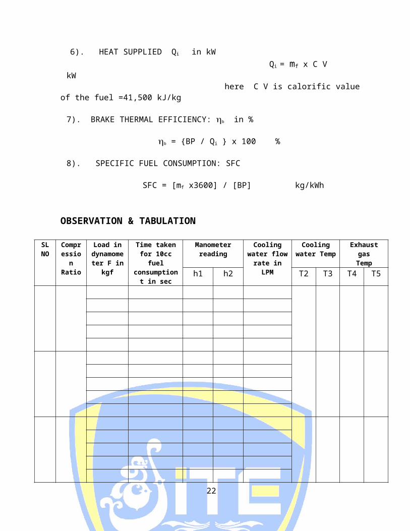
6). HEAT SUPPLIED Qi in kW Qi = mf x C V kW
here C V is calorific value of the fuel =41,500 kJ/kg
7). BRAKE THERMAL EFFICIENCY: b in %
b = {BP / Qi } x 100 % 8). SPECIFIC FUEL CONSUMPTION: SFC
16

SFC = [mf x3600] / [BP] kg/kWh
OBSERVATION & TABULATION
SL NO
Compressio
n Ratio
Load in dynamometer F in kgf
Time taken for 10cc
fuel consumption t in
sec
Manometer reading
Cooling water flow
rate in LPM
Cooling water Temp
Exhaust gas
Temph1 h2 T2 T3 T4 T5
RESULTS:-
SL NO
Compression Ratio
Load F in kgf
Air-Fuel Ratio
Brake PowerBP in kW
S F C in kg/kW-
hr
Volumetric Effy b
in %
Brake thermal Effi b in %
17

HEAT BALANCE SHEETHeat Input kJ/min % Heat output KJ/min %
A. By burning of fuelI,e Heat supplied Qi
100B) Heat equivalent to BP BP*60C) Heat carried by cooling Water = mw Cp (T1 – T3) D) Heat carried away by exhaust gas = mg x Cp (T5 – T6) E) Heat unaccountable [A-(B+C+D)]
Total input 100 Total output 100
Where ‘mw’ is mass flow of water Kg/min, = water flow in flow meter in Lpm Cp warter = 4.19 KJ/Kg 0 K. mg = (ma + mf) Kg/min. Cpair = 1.05 KJ/Kg 0 K.
18

EXPERIMENT NO: 6
STUDY OF BOILERS
Aim: To study the working of various types of steam generator (steam
boilers) Study of steam generators: Introduction :
A steam boiler is a closed vessel which boiler generator steam by transferring heat produced by burning of fuel to water . The steam boiler produced is used for power generation or process heating . Selection of steam generators :
[‘; The selection of type & size of a steam generator depends on the following factors . 1. The power required & working pressure. 2. The geographical position of power house. 3. The fuel & water available. 4. The probable load factor.
Classification of Boilers: The steam boilers are classified according to the following basic: 1. Flow of water & heat gases a. Fire tube boiler b. Water Tube boiler
2. Method of firing a. Internally fired b. Externally fired
3. Method of water circulation a. Natural circulation b. Forced circulation
4. Pressure developed a. Low pressure boiler b. High pressure boiler
19

5.
20

6. Nature of service a. Stationary boiler b. Mobile boiler
7. Design of gas passage a. Single phase b. Multi phase
High Pressure Boilers : Modern high pressure boilers generate steam at a pressure more than 75 bar . Example : Babcock & Wilcox boiler , Lamont boiler , BHEL boiler . Lamont Boiler : A forced circulating boiler was first introduced in 1725 by Camont . The arrangement is shown in the figure . The most of sensible heat is supplied to the feed water passing through the Economizer. A centrifugal pump circulates the water equal to 8 to 10 times the weight of steam evaporated tubes and the part of water supplied drum. The large quantity of water circulated prevents the tubes from being overheated . To secure the uniform flow of feed water through each of parallel boilers circuits a choke is fitted all the enhance to each circuits. BHELL BOILERS : It consists of feed pump, a economizer a boiler drum, radiant & connective super heaters , FD fan , air pre heaters 1 & 2 .Electro static precipitator 1D fan & chimney . The feed water from the hot well is pumped with the help of a feed pump to boiler from the through economy .In boiler drawn the fed water is circulated to number of valves in the furnaces with fuel is burnt. The feed water is evaporated into wet steam and the wet steam flows back to boiler drawn. In this its supplied to prime mover through steam outlet. The hot blue gases from the furnace pars over radiant & connective super heaters to super heat the steam. Then it passes through the pre heaters economizer and pre heater .Then the blue gases passes through the electrostatic precipitator.
21
Result : Thus the working of various types of steam generator (steam boiler ) was studied .
22

EXPERIMENT NO: 7TEST ON RECIPROCATING AIR COMPRESSOR
Ex No. : Date: Aim :
To conduct performance test on a two stage reciprocating compressor and to determine the volumetric efficiency. Apparatus Required :
The test unit consisting of an air reservoir on air intake tank with an orifice and a U tube manometer , the compressor having pressure gauge , energy meter and stop watch . Specification : Compressor Model : 2 stage reciprocating Diameter of low pressure piston = ...... mm Diameter of high pressure piston = ...... mm Stoke = ...... mm Speed = ...... rpm Tank Capacity = ...... liters Motor Capacity = ...... HP Formula Used :
1. Volumetric Efficiency = VaVt x100
Where : Va - actual volume of air compressor Vt -Theoretical volume of air
2. Actual volume of air compressed (Va) Va = Cd x A x √(2gh) m3 / sec Cd - Coefficient of discharge of orifice A - Orifice area in m2 = π d
2
4
H - Air head causing flow H = h x ρwaterρoil x100 = m of oil
h = ( h1 ~ h2 ) cm of water Tabulation :
Sl No. Reservoir Pressure gauge reading PKgf/Cm2
U- tube manometer reading
Time for 5 revolutions of energy meter (Sec)
h1 h2 h = (h1- h2)in cm
23

ρ water = 1000 kg/m3 ρ air = 1.162 kg/m3 at 30°C
= 1.6x 10001.16 x 100= 13.79 m of water
H = h1 ~ h2 cm of water ρw = 1000 kg/m3 ρoil = 1.173 kg/m3 at 29 °C
3. Theoretical Volume of air , VT = π d
2 ln4 x60
m3/sD - Diameter of piston – 0.7 m L - Stroke length – 0.085 m N - Speed – 850 rpm Isothermal η – VaVt x 100 Va - Actual volume of air compressor VT - Theoretical volume of air x - No of revolutions 5 Emc – Energy meter constant – 200 rev/hr t – time for 5 rev in seconds Compressor output = ρ a xVa1000 KW Pa – Atmospheric Pressure = 1 bar = 1 x 10⁵ N / m2 Va – Actual volume of air ( m3 / s ) C- Compression ratio = gauge pressure + Atmospheric pressure
Procedure: 1. Close the outlet valve. 2. Fill up the manometer with water up to half level. 3. Start the compressor and observe the pressure developing slowly. 4. At a particular test, pressure outlet valve is opened slowly and
adjuster so that pressure in tank and maintained constant. 5. Observe the following reading time taken for 5 revolution of energy
meter disc. Graph :
Thus performance test on a two stage reciprocating air compressor is conducted ηvol is also found .
Result :
Pressure I/P Power
24