Embed Size (px)
Citation preview

Remote RMM-1400Intelligent Remote Site Management Device
Installation Guide
Part Number 65-000062 Rev 3
© 2011 by Kentrox, Inc. All rights reserved.
Copyright © 2011 by Kentrox, Inc. All Rights Reserved. The material discussed in this publication is the proprietary property of Kentrox, Inc. Kentrox retains all rights to reproduction and distribution of this publication.
Kentrox is a registered trademark of Kentrox, Inc. Applied Innovation, Applied Innovation Inc., the AI logo, and other names are the intellectual property of Kentrox. All other product names are trademarks or registered trademarks of their respective owners.
Information published here is current as of this document’s date of publication, but is subject to change without notice. You may verify product information by contacting our headquarters. Kentrox is an Equal Opportunity/Affirmative Action employer.
Kentrox, Inc.5800 Innovation Dr.
Dublin, Ohio USA 43016-3271Toll Free: (800) 247-9482
International: +1 (614) 798-2000Fax: +1 (614) 798-1770

Remote RMM-1400Intelligent Remote Site Management Device
Installation GuideThis installation guide explains how to install the Remote RMM-1400 intelligent remote site management device.
Instructions for use of this product are detailed in the following documents:
Remote RMM-1400 Command Reference Guide
Remote RMM-1400 Configuration Guide
Guide to this document
Product Components
Cautions and Warnings
Customer Assistance
Required Items
Installation
Technical Specifications
1

Product Components
Product Components
Front Panel Components - Remote RMM-1400
Input Power and Battery Monitor
ConnectionsAsynchronous Serial Ports
Chassis Ground
ESD Ground
LED Description
Summary alarm LED: Illuminates when any point is in alarm state
Hardware failure LED:
—Illuminates when processor is not functioning, or when RMM-1400 has been powered up and bootloader is loading
—Blinks when bootloader has loaded and kernel is loading
—Goes out when RMM-1400 bootup is complete
DC Input Power LED: Illuminated when valid DC input power is applied to the unit
LED Status
DC
ALM
Unit Status LEDs
FLT
Ethernet Switch Ports
Tx/RxSMA Female Cellular/PCS
Antenna
DiversitySMA Female Cellular/PCS
Antenna
Serial ports 1 and 2 operateonly in RS-232 mode.
Serial ports 3 and 4 operatein RS-422 mode or RS-485 mode.
Ethernet ports 1 and 2provide 802.3af-compliant PoE.
Pins 1 and 2 (Rx) provide negative (-) output.Pins 3 and 6 (Tx) provide positive (+) output.
2

Cautions and Warnings
Cautions and Warnings
Grounding and Electrical Safety
CAUTION: Kentrox equipment and peripherals contain electrostatic sensitive components. Proper handling, shipping, and storage precautions must be exercised.
Installation
CAUTION: For Kentrox equipment to operate safely and correctly, there must be a safety ground strap between the equipment ground bolts and the office ground.
Environment
CAUTION: In the event that Remote RMM-1400 has been subjected to adverse environmental conditions, a service inspection of Remote RMM-1400 should be made to ensure safe operation.
Restricted Access Locations
CAUTION: The Remote RMM-1400 is for use in restricted access locations only.
FCCThe Federal Communications Commission has set limits for emitted radio interference, and Remote RMM-1400 is constructed with this electromagnetic interference (EMI) limitation in mind. Remote RMM-1400 is classified under FCC regulations as a Class A device, that is, a device for use in commercial environments and not in residential areas. This device has been tested and shown to comply with the following FCC rule: Part 15 Subpart J. Operation of this equipment in a residential area may cause interference to radio and TV reception, requiring the user to take whatever steps are necessary to correct the interference.
Information is available from the FCC describing possible corrective actions. To maintain low EMI levels, we suggest that you use only metal connectors and shielded cable grounded to the frame.
Specifications are subject to change without notice.
3

Customer Assistance
Customer AssistanceAll customers, partners, and resellers who have a valid Kentrox Support and Services Agreement have complete access to the technical support resources.
Kentrox offers technical support from 8 a.m. to 8 p.m. Eastern time, Monday - Friday.
Before you contact Kentrox for assistance, please have the following information available:
The version of hardware and software you are currently running
The error number and exact wording of any messages that appeared on your screen
What happened and what you were doing when the problem occurred
How you tried to solve the problem
Kentrox Online Knowledge BaseThe Kentrox Online Knowledge Base provides online documents and tools to help troubleshoot and resolve technical issues with Kentrox products and technologies.
To access the Kentrox Online Knowledge Base, use this URL:
http://kb.kentrox.com
Email SupportEmail support is available. You may send email at any time during the day; however, responses will be provided only during normal business hours, in accordance with your Service and Support Agreement.
To contact Technical Support, send email to:
Telephone Support
Pre-sales support Available, at no charge, to anyone who needs technical assistance in determining how Kentrox products or solutions can help solve your technical needs.
Phone number: 800-733-5511, option 2
Hours of Operation: 8 a.m. – 8p.m. Eastern Time
Post-sales supportAvailable to qualified Kentrox customers or partners who have not been able to resolve their technical issue by using our online services. To qualify for support, you must have a valid Support and Services Agreement.
4

Customer Assistance
Phone number: 800-733-5511, option 3
Normal Business Hours: 8 a.m. to 8 p.m. Eastern time
After-Hours Support: Available to qualified customers who are experiencing service-affecting outages that cannot wait until the next business day. To qualify for after-hours support, you must have a valid 24x7 Support and Services Agreement. Call the number above, option 3, and follow the prompts for after-hours service.
Product DocumentationYou can also access and view the most current versions of Kentrox product documentation on our Web site at:
http://www.kentrox.com
5
Required Items
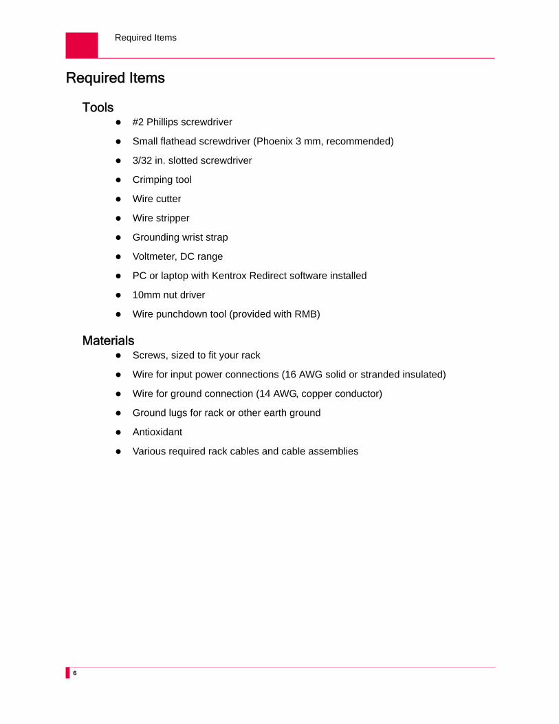
Required Items
Tools #2 Phillips screwdriver
Small flathead screwdriver (Phoenix 3 mm, recommended)
3/32 in. slotted screwdriver
Crimping tool
Wire cutter
Wire stripper
Grounding wrist strap
Voltmeter, DC range
PC or laptop with Kentrox Redirect software installed
10mm nut driver
Wire punchdown tool (provided with RMB)
Materials Screws, sized to fit your rack
Wire for input power connections (16 AWG solid or stranded insulated)
Wire for ground connection (14 AWG, copper conductor)
Ground lugs for rack or other earth ground
Antioxidant
Various required rack cables and cable assemblies
6

Installation
Installation
Step 1: Install Wireless Phone Module Hardware in Remote RMM-1400If your Remote RMM-1400 includes the wireless phone module, follow these steps to install the necessary hardware:
1. Affix the FCC sticker (included with the phone module) to the product label on Remote RMM-1400.
2. Remove the top cover from Remote RMM-1400 by removing two screws from each side panel, then sliding the top cover to the rear of the unit to release the locking flange as shown below. Lift the top cover off the unit.
CAUTION: Kentrox equipment and peripherals contain electrostatic sensitive components. Proper handling precautions must be exercised.
Locking Flange
Mounting Screws
(right side)
Mounting Screws (left side - second
screw hidden)
7

Installation
3. Install two antenna terminals by inserting them through the holes provided in the front of Remote RMM-1400. Secure the terminals in place by attaching a nut and lock washer to each terminal, as shown below.
4. Install the phone module by inserting one end in the socket on the motherboard. Next, press down the other end of the phone module until it locks in place.
5. Attach two antenna leads from the antenna terminals to the phone module as shown below.
6. Insert the SIM chip in the socket on the motherboard.
7. Reinstall the Remote RMM-1400 top cover by placing the top cover on the chassis, sliding it forward until the flange locks under the faceplate, then reinserting two screws in each side panel.
SIM Chip
Phone Module
Antenna Leads
Antenna Terminals
Nuts
Lock Washers
8

Installation
Step 2: Attach Mounting Flanges to Remote RMM-1400Attach the mounting flanges to fit a 19-inch or 23-inch rack. You can attach the flanges in alternate locations providing multiple alignment options to the rack.
Mounting flanges oriented for a 19-inch rack
Mounting flanges oriented for a 23-inch rack
9

Installation
Step 3: Attach Remote RMM-1400 to RackInstall mounting screws into the mounting holes and tighten firmly. No space is required between Remote RMM-1400 and any component mounted above or below Remote RMM-1400.
10

Installation
Step 4: Attach Chassis GroundConnect the chassis ground of Remote RMM-1400 to a suitable ground such as the frame ground of the rack system or a reliable earth ground.
Note: Apply an appropriate antioxidant to the bare conductors before crimping the connector to the connector mating surface.
The chassis ground must be connected to the same earthing electrode conductor as the DC supply system or to a bonding jumper (from an earthing terminal or bus) connected to the earthing electrode of the DC supply system.
The chassis must be located in the same immediate area (such as adjacent cabinets) as other equipment connected to the same DC power system and earthing electrode conductor. The DC system cannot be earthed elsewhere.
The DC power source must be located in the same premises as the chassis.
No switching or disconnecting devices can occur between the earthed conductor of the DC source and the earthing electrode conductor.
Caution:
Note: For ground connection, use 14AWG or larger conductor.
11

Installation
Step 5: Connect Input Power
WARNING: Turn off the power feed before connecting wires.
Connect the input power feed to the power supply connector. Be careful to observe polarity.
Unscrew these two screws to remove thepower connector, if necessary.
Notes:
Connect power connector to a reliably grounded -48 VDC safety extra-low voltage (SELV) source.
Use 16 AWG or larger copper conductors.
Typical circuit fuse: 3 A
A readily accessible disconnect device (suitably approved and rated) must be incorporated in the field wiring.
Caution:
To connect wires:1. Turn off power feed.
2. Strip ends of wire 5/16 in. (7 mm).
3. (optional) Using a small flathead screwdriver, loosen screws on sides of power connector on rear panel of Remote RMM-1400.
4. (optional) Remove power connector.
5. Using a 3/32 in. slotted screwdriver, loosen the six screws at top of connector.
6. Insert wire into connector and tighten screws.
12

Installation
Step 6: Mount RMBMount the RMB peripheral unit to the wall, or in a rack. See the RMB Installation Guide for instructions.
Step 7: Connect RMB Inputs and OutputsRMB input and output connections are made using the supplied punchdown tool. See the RMB Installation Guide for an explanation of RMB inputs and outputs.
Step 8: Connect the Port CablesConnect all port cables per your application.
Connecting RMM-1400 to RMBUse a standard CAT5 Ethernet cable (such as Kentrox part number CAB182-10) to connect one of RMM-1400’s PoE-enabled Ethernet ports to the Ethernet port on RMB.
CAUTION: Kentrox recommends disconnecting the Ethernet PoE cable to RMB before wiring inputs and outputs in order to avoid electrical shorts.
Connecting to an Asynchronous Serial PortAsynchronous serial ports allow terminal devices with asynchronous serial ports (such as PCs, NEs, and asynchronous modems) to connect to Remote RMM-1400.
Use one of the following cables to connect one of the asynchronous serial ports (labeled SERIAL on the front panel) to an external device, such as a modem:
8-pin modular plug to 8-pin modular plug rollover DTE to DTE null RS-232 cable (part number CAB213)
Male DB-25 to 8-pin modular plug DTE to DCE straight cable (part number CAB214)
Female DB-25 to 8-pin modular plug DTE to DTE null RS-232 cable (part number CAB564)
Female DB-9 to 8-pin modular plug DTE to DTE null RS-232 cable (part number CAB562)
Note: Use shielded cable to ensure compliance with applicable emission standards.
Connecting to a Switched Ethernet PortThe switched Ethernet ports allow you to connect Ethernet-capable devices to Remote RMM-1400 and allow you to connect Remote RMM-1400 to a LAN.
Use an 8-pin modular plug to 8-pin modular plug straight 100BaseT cable (such as Kentrox part number CAB182) to connect one of the switched Ethernet ports (labeled
13

Installation
ETHERNET on the Remote RMM-1400 front panel) to an Ethernet device on your network.
Connecting Wires to RMB Punchdown TerminalsTo connect a wire to a punchdown terminal on RMB-1 or RMB-2:
1. Insert the wire in the slot in the top of the punchdown terminal and hold it in place.
2. Place the metal blade of the punchdown tool on top of the wire and press down firmly until the wire is seated in the bottom of the terminal. This action secures the wire in place and strips insulation from the wire. Pre-stripping the wire is not necessary.
3. Trim away any excess wire.
4. (optional) Gently tug the wire to ensure it is securely connected to the terminal.
Step 9: Configure an IP AddressConfiguring the IP address allows Remote RMM-1400 to be accessed remotely.
To configure the IP address:
1. Install Kentrox Redirect software on your laptop or PC. When the installation is complete, Kentrox Redirect and Kentrox Kickstart icons appear on your desktop.
2. Use a standard CAT5 Ethernet cable (such as Kentrox part number CAB182-10) to connect the PC or laptop to an Ethernet port on Remote RMM-1400.
3. Launch Kentrox Kickstart. Kickstart discovers the Remote RMM-1400 device, as shown below.
Note: If the Remote RMM-1400 device is not discovered within one minute,
select Help > About in Kentrox Kickstart, then click the Network Troubleshooting Guide link for instructions.
4. Click Telnet Terminal (or select Tools > Telnet Terminal). A Telnet window opens, displaying the Remote RMM-1400 login prompt.
5. At the Remote RMM-1400 login prompt, enter admin. This is the default login.
14

Technical Specifications
6. At the password prompt, enter password. This is the default password.
7. At the command prompt, enter config interface bridge switch ip address, followed by the IP address and subnet mask. For example:
config interface bridge switch ip address 10.34.64.222 255.255.255.0
8. At the command prompt, enter config ip route default and the default gateway address. For example:
config ip route default 172.10.11.222
Technical Specifications
Table 1 Technical Specifications
Specification Description
Weight 3.35 lb (1.5 kg)
Size Height: 1.6 in. (4.1 cm)Width: 11.8 in. (30.0 cm)Depth: 8.6 in. (21.8 cm)
Mounting Mounts in a standard 19-in. or 23-in. rack
Operating Environment(Ambient)
Temperature: -30° to 60°C (-22° to 140° F)Relative humidity: 0% to 95% (non-condensing)
Power Dual input (A/B feed), 40 watts maximumInput voltage range: +/- 20 to 60VDC (both power feeds must have the same polarity)In-rush: 3A maximum - no greater than 2A for no longer than 2ms
Fuse Ratings 3 A at 60 VDC
Input/Output Ports 4 10/100 BaseT Ethernet switch ports, 2 with 802.3af-compliant PoE2 RS-232 asynchronous serial ports2 RS-422/RS-485 asynchronous serial ports2 20-60 VDC power inputs with voltage monitoring1 auxiliary 0-60 VDC voltage monitoring input
15

Technical Specifications
16