Embed Size (px)
Citation preview
ROBOMOTE: ENABLING MOBILITY IN SENSOR NETWORKS
Karthik Dantu, Mohammad Rahimi, Hardik Shah, Sandeep Babel, Amit Dhariwal, Gaurav S. Sukhatme
Dept of Computer Science,University of Southern California,
941 W 37th Place,Los Angeles, CA 90089.
Email: (dantu|mhr|babel|dhariwal|gaurav)@usc.edu, [email protected]
ABSTRACT
Severe energy limitations, and a paucity of computation pose a setof difficult design challenges for sensor networks. Recent progressin two seemingly disparate research areas namely, distributed roboticsand low power embedded systems has led to the creation of mobile(or robotic) sensor networks. Autonomous node mobility bringswith it its own challenges, but also alleviates some of the tradi-tional problems associated with static sensor networks. We illus-trate this by presenting the design of the robomote, a robot plat-form that functions as a single mobile node in a mobile sensornetwork. We briefly describe two case studies where the robomotehas been used for table top experiments with a mobile sensor net-work.
1. INTRODUCTION
Sensor networks hold the promise of revolutionizing our daily lifeby ubiquitously monitoring our environment and/or adjusting it tosuit our needs. The benefits of this technology have been elabo-rated at length in the literature [1, 2, 3, 4]. The realization of suchnetworks poses many challenges which are the subject of activeresearch in the field. These include challenges stemming directlyfrom the paucity of computation, storage and energy, systems chal-lenges such as unattended long term function, routing and dis-tributed computation (e.g., for localization, calibration, time syn-chronization), and finally, challenges associated with the dynamicsand spatio-temporal irregularity of the environments within whichthese networks are expected to function.
As an illustration of the utility of autonomous node mobilitywithin sensor networks we present the hardware and software de-sign of the robomote, a robot platform that functions as a singlemobile node in a mobile sensor network. We describe two casestudies where the robomote has been used for table top experi-ments with a mobile sensor network. For design and usage detailsbeyond those described in this paper, the reader is directed to therobomote website http://robotics.usc.edu/∼robomote.
2. APPLICATIONS OF MOBILITY
Controlled mobility enables a whole new set of possibilities in sen-sor networks. The ability to actively change location can be used tomitigate/solve many of the design challenges outlined above. Be-fore we look at some of the advantages, we would like to clarifythat controlled or robotic mobility is different from mobility in the
context of Mobile Adhoc Networks (MANETs). MANET studiesconsider mobility as a given (e.g., as experienced by portable de-vices such as cell phones or laptops). They study the effects ofmobility and assume no control over it. However, controlled orrobotic mobility is the ability of a network to move intentionally,and without human assistance. We outline some of advantages ofcontrolled mobility below.
Deployment: Controlled mobility can be used to deploy sen-sors at optimal locations for monitoring. As an example see [5]wherein an algorithm for deploying a fully mobile sensor networkhas been proposed. We could conceive of a family of algorithmsfor deployments that have varying ratios of static to mobile sensornodes that optimize various metrics like maximum coverage, re-quired connectivity [6] etc.
Adaptive Sampling: One of the fundamental requirementsfrom a sensor network is to sample its environment. It is possibleto think of adaptive sampling strategies where spatial adaptation isby the use of mobility [7] since it is not possible to deploy sensorsat all possible sampling locations a priori.
Network Repair: One of the main problems of adhoc de-ployment is the lack of guaranteed connectivity (or a certain levelof connectivity) in the network. Such situations can be correctedby having a few mobile nodes which can actively move to desiredlocations and repair broken networks.
Energy Harvesting: Methods have been suggested [8] to usemobile sensor nodes to physically transport energy in the networkfrom areas where it is available in plenty to other regions where en-ergy availability is scarce. Using such techniques self-sustainingnetworks which rely on sources like solar energy could be built,thereby mitigating the energy constraint which is fundamental tosensor network design.
Event Detection: Detecting spatially and temporally spreadenvironmental events is a fundamental function of a sensor net-work. An initial network deployment might not be the optimaldeployment of nodes to detect events in time. We can correctthis problem by having mobile nodes that move to regions of highprobability of event detection over time. This arrangement couldalso be dynamic with mobile nodes repositioning themselves [5]as and when required.
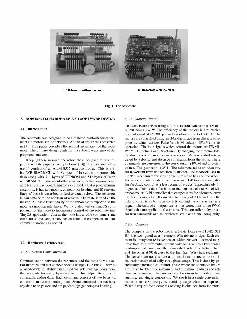
Fig. 1. The robomote
3. ROBOMOTE: HARDWARE AND SOFTWARE DESIGN
3.1. Introduction
The robomote was designed to be a tabletop platform for experi-ments in mobile sensor networks. An initial design was presentedin [9]. This paper describes the second incarnation of the robo-mote. The primary design goals for the robomote are ease of de-ployment, and cost.
Keeping these in mind, the robomote is designed to be com-patible with the popular mote platform ([10]). The robomote (Fig-ure 1) consists of an Atmel 8535 microcontroller. This is a 8-bit AVR RISC MCU with 8k bytes of In-system programmableflash along with 512 bytes of EEPROM and 512 bytes of Inter-nal SRAM. The microcontroller also incorporates various desir-able features like programmable sleep modes and reprogrammingcapability. It has two motors, compass for heading and IR sensors.Each of these is described in further detail below. The robomoteis complete with the addition of a mote. The mote is used as themaster. All basic functionality of the robomote is exported to themote via modular interfaces. We have also written TinyOS com-ponents for the mote to incorporate control of the robomote intoTinyOS application. Just as the mote has a radio component andcan send out packets, it now has an actuation component and cancommand motions as needed.
3.2. Hardware Architecture
3.2.1. Internal Communication
Communication between the robomote and the mote is via a se-rial interface and can achieve speeds of upto 19.2 kbps. There isa byte-to-byte reliability established via acknowledgements fromthe robomote for every byte received. This helps detect loss ofcommands and/or data. Each command consists of two bytes - acommand and corresponding data. Some commands do not haveany data to be passed and are padded (eg: get compass heading).
3.2.2. Motion Control
The wheels are driven using DC motors from Micromo at 6V andoutput power 1.41W. The efficiency of the motors is 71% with ano-load speed of 16,300 rpm and a no-load current of 30 mA. Themotors are controlled using an H-bridge, made from discrete com-ponents, which utilizes Pulse Width Modulation (PWM) for itsoperation. The four signals which control the motors are PWM1,PWM2, Direction1 and Direction2. By changing the direction bits,the direction of the motors can be reversed. Motion control is trig-gered by velocity and distance commands from the mote. Thesecommands are converted to the corresponding PWM and directionvalues. The gear ratio is 25:1. The robomote relies on odometryfor movement from one location to another. The feedback uses IRTX/RX mechanism for sensing the number of ticks on the wheel.For one complete revolution of the wheel, 150 ticks are availablefor feedback control at a least count of 6 ticks (approximately 14degrees). This is then fed back to the counters of the Atmel Mi-crocontroller. A PI controller that compensates for odometry errorhas been constructed. It runs at a frequency of 2 Hz and uses thedifference in ticks between the left and right wheels as an errorsignal. The controller outputs are sent as corrections to the PWMsignals that are applied to the motors. This controller is bypassedfor turn commands and calibration to avoid additional complexity.
3.2.3. Compass
The compass on the robomote is a 2-axis Honeywell HMC1022IC. It is configured as a 4-element Wheatstone bridge. Each ele-ment is a magneto-resistive sensor which converts a sensed mag-netic field to a differential output voltage. From this two analogreadings are obtained, one that senses the Earth’s North-South fieldand the other at 90 degrees to the first (i.e. West-East readings).The sensors are not absolute and must be calibrated at robot ini-tialization and periodically throughout usage. This is done by pe-riodically entering a calibration phase where the robomote makesa full turn to detect the maximum and minimum readings and setsthem as reference. The compass can be run in two modes: free-running, and single conversion. We use it in a single conversionmode to conserve energy by avoiding usage when not required.When a request for a compass reading is obtained from the mote,
current is passed through the compass. This causes the compass toactivate and the azimuth reading is obtained which is passed backto the mote.
mote
IR
Atmel 8535
Robomote
Atmega
52-pin connector
Compass
Motors
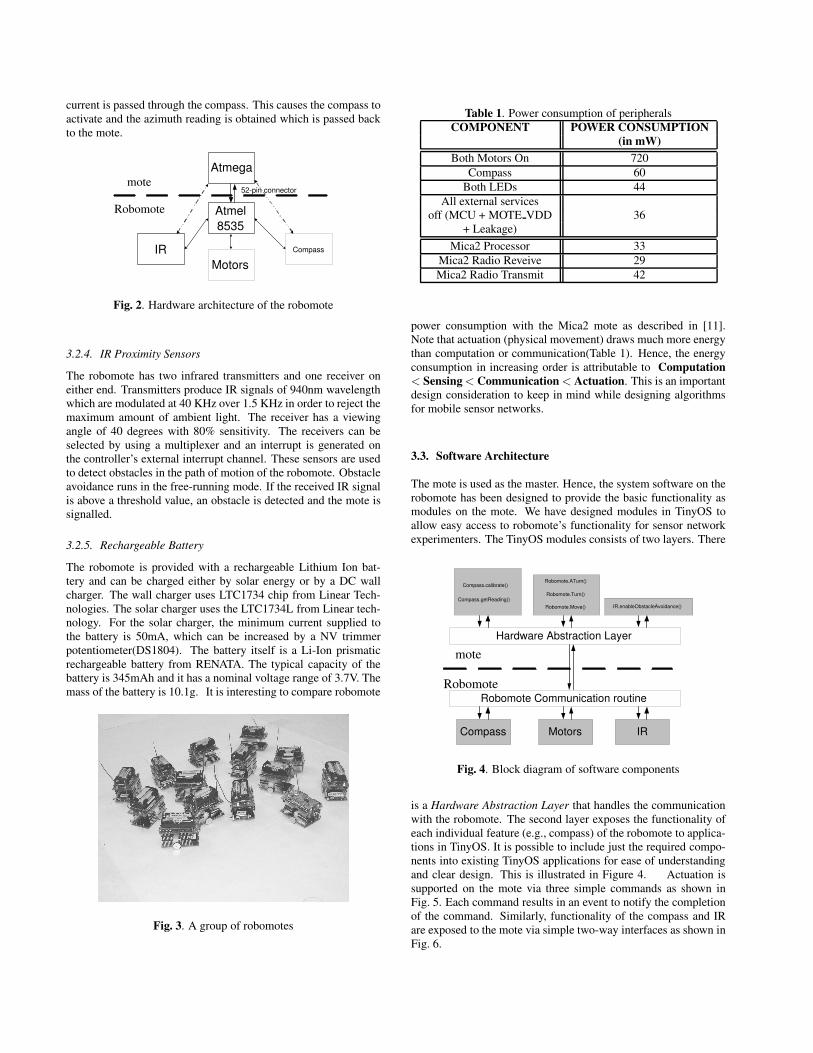
Fig. 2. Hardware architecture of the robomote
3.2.4. IR Proximity Sensors
The robomote has two infrared transmitters and one receiver oneither end. Transmitters produce IR signals of 940nm wavelengthwhich are modulated at 40 KHz over 1.5 KHz in order to reject themaximum amount of ambient light. The receiver has a viewingangle of 40 degrees with 80% sensitivity. The receivers can beselected by using a multiplexer and an interrupt is generated onthe controller’s external interrupt channel. These sensors are usedto detect obstacles in the path of motion of the robomote. Obstacleavoidance runs in the free-running mode. If the received IR signalis above a threshold value, an obstacle is detected and the mote issignalled.
3.2.5. Rechargeable Battery
The robomote is provided with a rechargeable Lithium Ion bat-tery and can be charged either by solar energy or by a DC wallcharger. The wall charger uses LTC1734 chip from Linear Tech-nologies. The solar charger uses the LTC1734L from Linear tech-nology. For the solar charger, the minimum current supplied tothe battery is 50mA, which can be increased by a NV trimmerpotentiometer(DS1804). The battery itself is a Li-Ion prismaticrechargeable battery from RENATA. The typical capacity of thebattery is 345mAh and it has a nominal voltage range of 3.7V. Themass of the battery is 10.1g. It is interesting to compare robomote
Fig. 3. A group of robomotes
Table 1. Power consumption of peripheralsCOMPONENT POWER CONSUMPTION
(in mW)Both Motors On 720
Compass 60Both LEDs 44
All external servicesoff (MCU + MOTE VDD 36
+ Leakage)Mica2 Processor 33
Mica2 Radio Reveive 29Mica2 Radio Transmit 42
power consumption with the Mica2 mote as described in [11].Note that actuation (physical movement) draws much more energythan computation or communication(Table 1). Hence, the energyconsumption in increasing order is attributable to Computation< Sensing < Communication < Actuation. This is an importantdesign consideration to keep in mind while designing algorithmsfor mobile sensor networks.
3.3. Software Architecture
The mote is used as the master. Hence, the system software on therobomote has been designed to provide the basic functionality asmodules on the mote. We have designed modules in TinyOS toallow easy access to robomote’s functionality for sensor networkexperimenters. The TinyOS modules consists of two layers. There
mote
Robomote Robomote Communication routine
Hardware Abstraction Layer
IR.enableObstacleAvoidance() Robomote.Move()
Robomote.ATurn()
Robomote.Turn() Compass.getReading()
Compass.calibrate()
Compass Motors IR
Fig. 4. Block diagram of software components
is a Hardware Abstraction Layer that handles the communicationwith the robomote. The second layer exposes the functionality ofeach individual feature (e.g., compass) of the robomote to applica-tions in TinyOS. It is possible to include just the required compo-nents into existing TinyOS applications for ease of understandingand clear design. This is illustrated in Figure 4. Actuation issupported on the mote via three simple commands as shown inFig. 5. Each command results in an event to notify the completionof the command. Similarly, functionality of the compass and IRare exposed to the mote via simple two-way interfaces as shown inFig. 6.
command Robomote.Move(uint8 t distance)− Move straight for distance cm.
command Robomote.Turn(uint8 t angle, uint8 t direction)− Turn relative to current position inanti−clockwise(direction=1)/clockwise(direction=0)by angle degrees.
command Robomote.ATurn(uint8 t angle)− Turn to absolute position angle degrees.
event result t Robomote.MoveDone()− Signify completion of the move command.
event result t Robomote.TurnDone()− Signify completion of the turn command.
event result t Robomote.ATurnDone()− Signify completion of the absolute turn command.
Fig. 5. Actuation Interface provided by robomote
command result t Compass.calibrate()− Calibrate the compass.
event result t Compass.calibrateDone()− Signal end of calibration of compass.
command result t Compass.getData()− Get the compass reading.
event result t Compass.dataDone(uint8 t az)− Signal end of compass reading.
command result t IR.enableObstacleAvoidance()− Enable signalling of obstacles.
event result t IR.obstacle()− Signal presence of obstacle.
Fig. 6. IR sensors and Compass Interface
4. CASE STUDIES - EXPERIMENTS USING THEROBOMOTE AS A MOBILE SENSOR NODE
4.1. Detecting Level Sets of Scalar Fields using a Mobile Sen-sor Network
4.1.1. Problem
A static sensor network is deployed in a bounded area. The prob-lem is to detect level sets(contours) of the sensed scalar field (e.g.,isobars for pressure, isotherms for temperature). A single mobilesensor node is available in addition to the ensemble of static nodes.
4.1.2. Algorithm
We use a control law proposed in the context of sensor-based pathplanning [12] for this purpose. The control law has been adaptedfor the sensor network case. The mobile nodes queries static nodesin its neighborhood and computes the optimal location velocityusing field gradient information from each neighbor. Simulation
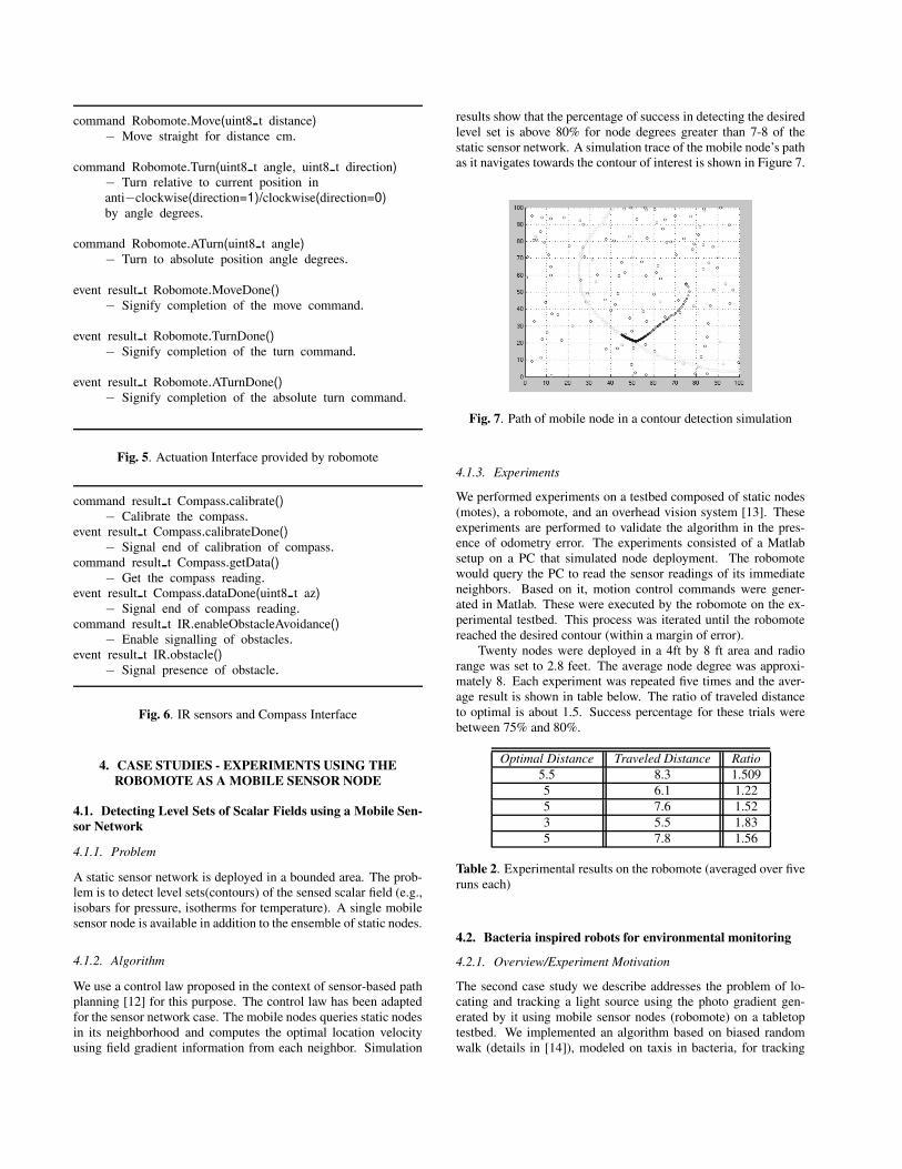
results show that the percentage of success in detecting the desiredlevel set is above 80% for node degrees greater than 7-8 of thestatic sensor network. A simulation trace of the mobile node’s pathas it navigates towards the contour of interest is shown in Figure 7.
Fig. 7. Path of mobile node in a contour detection simulation
4.1.3. Experiments
We performed experiments on a testbed composed of static nodes(motes), a robomote, and an overhead vision system [13]. Theseexperiments are performed to validate the algorithm in the pres-ence of odometry error. The experiments consisted of a Matlabsetup on a PC that simulated node deployment. The robomotewould query the PC to read the sensor readings of its immediateneighbors. Based on it, motion control commands were gener-ated in Matlab. These were executed by the robomote on the ex-perimental testbed. This process was iterated until the robomotereached the desired contour (within a margin of error).
Twenty nodes were deployed in a 4ft by 8 ft area and radiorange was set to 2.8 feet. The average node degree was approxi-mately 8. Each experiment was repeated five times and the aver-age result is shown in table below. The ratio of traveled distanceto optimal is about 1.5. Success percentage for these trials werebetween 75% and 80%.
Optimal Distance Traveled Distance Ratio5.5 8.3 1.5095 6.1 1.225 7.6 1.523 5.5 1.835 7.8 1.56
Table 2. Experimental results on the robomote (averaged over fiveruns each)
4.2. Bacteria inspired robots for environmental monitoring
4.2.1. Overview/Experiment Motivation
The second case study we describe addresses the problem of lo-cating and tracking a light source using the photo gradient gen-erated by it using mobile sensor nodes (robomote) on a tabletoptestbed. We implemented an algorithm based on biased randomwalk (details in [14]), modeled on taxis in bacteria, for tracking
gradient sources. Using gradient information and a rudimentarymotion strategy, the mobile sensor nodes are able to track gradientsources analogous to the manner in which bacteria detect and trackpotential food sources using locally sensed gradients.
4.2.2. Experiments with robomote
We carried out experiments on the robomote to validate our sim-ulation results with actual mobile sensor nodes executing a biasedrandom walk. We used a MICA mote to provide the control com-mands to the robomote using TinyOS. We used the two basic com-ponents move and rotate for controlling the robomote to carryout the biased random walk. We used a basic sensor board witha photo detector that could sense the light gradient generated bythe light source. The position of the robomote on the testbed wastracked using an overhead vision system which captured imageframes and passed these to a tracker for data analysis and storage.
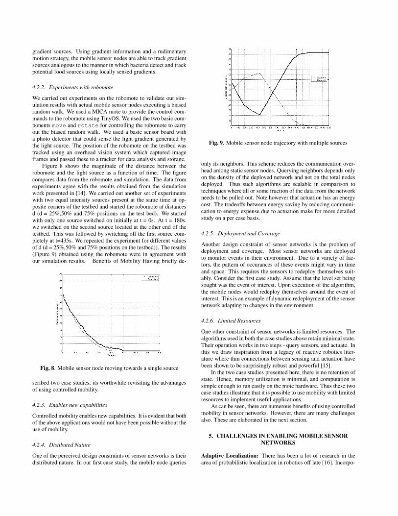
Figure 8 shows the magnitude of the distance between therobomote and the light source as a function of time. The figurecompares data from the robomote and simulation. The data fromexperiments agree with the results obtained from the simulationwork presented in [14]. We carried out another set of experimentswith two equal intensity sources present at the same time at op-posite corners of the testbed and started the robomote at distancesd (d = 25%,50% and 75% positions on the test bed). We startedwith only one source switched on initially at t = 0s. At t = 180s.we switched on the second source located at the other end of thetestbed. This was followed by switching off the first source com-pletely at t=435s. We repeated the experiment for different valuesof d (d = 25%,50% and 75% positions on the testbed)). The results(Figure 9) obtained using the robomote were in agreement withour simulation results. Benefits of Mobility Having briefly de-
Fig. 8. Mobile sensor node moving towards a single source
scribed two case studies, its worthwhile revisiting the advantagesof using controlled mobility.
4.2.3. Enables new capabilities
Controlled mobility enables new capabilities. It is evident that bothof the above applications would not have been possible without theuse of mobility.
4.2.4. Distibuted Nature
One of the perceived design constraints of sensor networks is theirdistributed nature. In our first case study, the mobile node queries
Fig. 9. Mobile sensor node trajectory with multiple sources
only its neighbors. This scheme reduces the communication over-head among static sensor nodes. Querying neighbors depends onlyon the density of the deployed network and not on the total nodesdeployed. Thus such algorithms are scalable in comparison totechniques where all or some fraction of the data from the networkneeds to be pulled out. Note however that actuation has an energycost. The tradeoffs between energy saving by reducing communi-cation to energy expense due to actuation make for more detailedstudy on a per case basis.
4.2.5. Deployment and Coverage
Another design constraint of sensor networks is the problem ofdeployment and coverage. Most sensor networks are deployedto monitor events in their environment. Due to a variety of fac-tors, the pattern of occurances of these events might vary in timeand space. This requires the sensors to redeploy themselves suit-ably. Consider the first case study. Assume that the level set beingsought was the event of interest. Upon execution of the algorithm,the mobile nodes would redeploy themselves around the event ofinterest. This is an example of dynamic redeployment of the sensornetwork adapting to changes in the environment.
4.2.6. Limited Resources
One other constraint of sensor networks is limited resources. Thealgorithms used in both the case studies above retain minimal state.Their operation works in two steps - query sensors, and actuate. Inthis we draw inspiration from a legacy of reactive robotics liter-ature where thin connections between sensing and actuation havebeen shown to be surprisingly robust and powerful [15].
In the two case studies presented here, there is no retention ofstate. Hence, memory utilization is minimal, and computation issimple enough to run easily on the mote hardware. Thus these twocase studies illustrate that it is possible to use mobility with limitedresources to implement useful applications.
As can be seen, there are numerous benefits of using controlledmobility in sensor networks. However, there are many challengesalso. These are elaborated in the next section.
5. CHALLENGES IN ENABLING MOBILE SENSORNETWORKS
Adaptive Localization: There has been a lot of research in thearea of probabilistic localization in robotics off late [16]. Incorpo-
rating mobility into sensor networks would need distributed lightweightimplementations of such algorithms to implement localization insensor networks.
Coverage: Maximizing coverage [17] in sensor networks us-ing static and mobile nodes has received some attention. However,there has not been much work on mobile sensor networks and howthey could be used to adapt networks by varying coverage dynam-ically.
Massive Reprogramming: Massive reprogramming of sen-sor networks is one of the envisioned problems [18]. It is possibleto consider solutions using mobile nodes that travel across the ge-ography of the sensor network, reprogramming parts of it.
Distributed Calibration: Another hard problem in sensornetworks is calibrating the sensors, particularly when the sensorsused are cheap and erroneous. We can think of having a calibratedsensor on a mobile node and the mobile node covering the area ofsensor node deployment calibrating the nodes in its neighborhood.
Network Repair: An interesting area of work is that of net-work repair. As mentioned earlier, it can be imagined that a fewmobile nodes can be used to repair static networks by positioningthemselves at hotspots or points of disconnection. However, mov-ing the mobile nodes expends energy and there is scope for studyof the tradeoff. This also makes for interesting theoretical studyfor optimal algorithms to move the mobile nodes.
6. CONCLUSIONS
We presented the robomote, a mobile robotic testbed for mobilesensor network experiments. We also presented two case stud-ies where the robomote was used to experimentally validate algo-rithms designed for next generation mobile sensor networks. Fi-nally, we enumerated some of the potential issues that need to beresolved in order to enable mobility in sensor networks.
7. REFERENCES
[1] Joseph Kahn, Randy Katz, and Kris Pister, “Next centurychallenges: Mobile networking for smart dust,” in Proceed-ings of Mobile Computing and Networking. ACM.
[2] Deborah Estrin, Ramesh Govindan, and John Heidemann,“Embedding the Internet,” Communications of the ACM, vol.43, no. 5, pp. 39–41, May 2000, (special issue guest editors).
[3] Greg Pottie and William J. Kaiser, “Wireless integrated net-work sensors,” Communications of the ACM, vol. 43, no. 5,pp. 551–8, May 2000.
[4] National Research Council Staff, Embedded Everywhere: AResearch Agenda for Networked Systems of Embedded Com-puters, National Academy Press, 2001.
[5] Andrew Howard, Maja Mataric, and Gaurav S. Sukhatme,“Self-deployment algorithm for mobile sensor networks,”Autonomous Robots - Special Issue on Intelligent EmbeddedSystems, vol. 13, no. 2, pp. 113–126, 2002.
[6] Sameera Poduri and Gaurav Sukhatme, “Constrained cover-age for mobile sensor networks,” in Proceedings of the IEEEInternational Conference on Robotics and Automation, Apr.2004.
[7] Maxim Batalin, Mohammad Rahimi, Yan Yu, Duo Liu,Aman Kansal, Gaurav Sukhatme, William Kaiser, MarkHansen, Gregory J Pottie, Mani Srivastava, and Deborah Es-trin, “Call and response: Experiments in sampling the en-vironment,” in Proceedings of 2nd Annual Conference onSensors and Systems (Sensys 2004), Baltimore, MD, USA.,November 2004, ACM.
[8] Mohammad H. Rahimi, Hardik Shah, Gaurav S. Sukhatme,John Heidemann, and Deborah Estrin, “Energy harvestingin mobile sensor networks,” in Proceedings of the IEEE In-ternational Conference on Robotics and Automation, Taipei,Taiwan, September 2003.
[9] Gabriel T. Sibley, Mohammad H. Rahimi, and Gaurav S.Sukhatme, “A tiny mobile robot platform for large-scalesensor networks,” in Proceedings of the IEEE InternationalConference on Robotics and Automation, Washington DC,USA, May 2002.
[10] Jason Hill, Robert Szewczyk, Alec Woo, Seth Hollar, DavidCuller, and Kris Pister, “System architecture directions fornetworked sensors,” in Proceedings of Architectural Sup-port for Programming Languages and Operating Systems-IX,Cambridge, MA, USA., Nov. 2000, ACM.
[11] Joseph Polastre, Robert Szewczyk, Cory Sharp, and DavidCuller, “The mote revolution: Low power wireless sensornetwork devices,” in In Proceedings of Hot Chips 16: ASymposium on High Performance Chips, August 2004.
[12] Howie Choset, Ilhan Konukseven, and Alfred Rizzi, “Sensorbased planing: A control law for generating the generalizedvoronoi graph,” in IEEE International Conference in Ad-vanced Robotics, 1997.
[13] Mohammad Rahimi, Rohit Mediratta, Karthik Dantu, andGaurav Sukhatme, “A testbed for experiments with sen-sor/actuator networks,” Tech. Rep. IRIS-02-417, Institute forRobotics and Intelligent Systems, 2002.
[14] Amit Dhariwal, Gaurav S. Sukhatme, and Aristides A. Re-quicha, “Bacterium-inspired robots for environmental mon-itoring,” in IEEE International Conference on Robotics andAutomation, April 2004.
[15] Rodney Brooks, “A robust layered control system for a mo-bile robot,” International Journal of Robotics and Automa-tion, vol. 2, pp. 14–23, 1986.
[16] Sebastian Thrun, Dieter Fox Wolfram Burgard, and FrankDellaert, “Robust monte carlo localization for mobilerobots,” Artificial Intelligence (AIJ), 2001.
[17] Maxim Batalin and G. S. Sukhatme, “Coverage, explorationand deployment by a mobile robot and communication net-work,” in Proceedings of the 2nd International Workshop onInformation Processing in Sensor Networks, Palo Alto Re-search Center (PARC) Palo Alto, CA, USA, April 2003, pp.376–391.
[18] Jonathan Hui and David Culler, “The dynamic behaviourof data dissemination protocol of network programming atscale,” in Proceedings of second annual conference in Sen-sors and Systems (Sensys).