Embed Size (px)
DESCRIPTION
rotary BHA for directional drilling
Citation preview
Rotary (B)ottom (H)ole (A)ssembly
Objectives
• Describe the minimum number of BHA changes needed in:– a slant directional well – an “S” type directional well
• Describe what is meant by:– bit side force– fulcrum effect– pendulum effect
• Explain the effect of drill collar stiffness in BHA design
Objectives #2
• Explain why minimizing the number of DC's and stabilizers is advisable in directional BHA's
• Describe the effect of an under gauge near-bit stabilizer in:– drop-off BHA's– build-up BHA's
• Show why an under gauge second is used in a locked BHA for tangent section
• Describe the effect of hole washout on BHA behavior
Objectives #3
• Describe the effect of drilling parameters have on inclination & direction with each type of BHA
• Explain why frequent surveys is advisable when an MWD tool is available
• Give examples of typical BHA designed to build and drop inclination at various rates
Drilling - Deflection Devices
• Tools & Techniques to deflect the course of the well in a controlled manner, (overcoming “natural” tendencies) eg., to:– Kick-off, nudge (build angle from vertical to a
desired direction) – Trajectory correction (turn, build, drop to the
desired trajectory) – Sidetrack (deflect the well from it’s original
course)
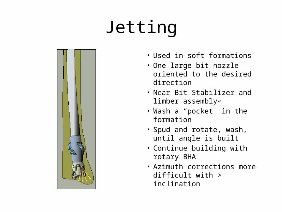
Jetting• Used in soft formations• One large bit nozzle oriented to
the desired direction• Near Bit Stabilizer and limber
assembly• Wash a “pocket” in the
formation• Spud and rotate, wash, until
angle is built• Continue building with rotary
BHA• Azimuth corrections more
difficult with > inclination
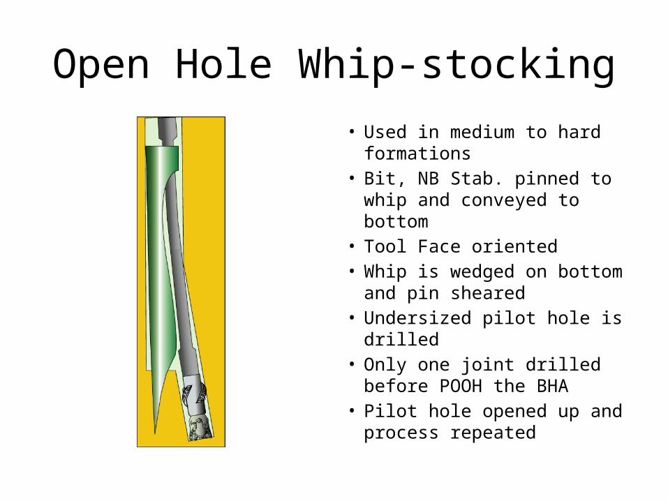
Open Hole Whip-stocking• Used in medium to hard
formations• Bit, NB Stab. pinned to whip
and conveyed to bottom• Tool Face oriented• Whip is wedged on bottom
and pin sheared• Undersized pilot hole is drilled• Only one joint drilled before
POOH the BHA• Pilot hole opened up and
process repeated
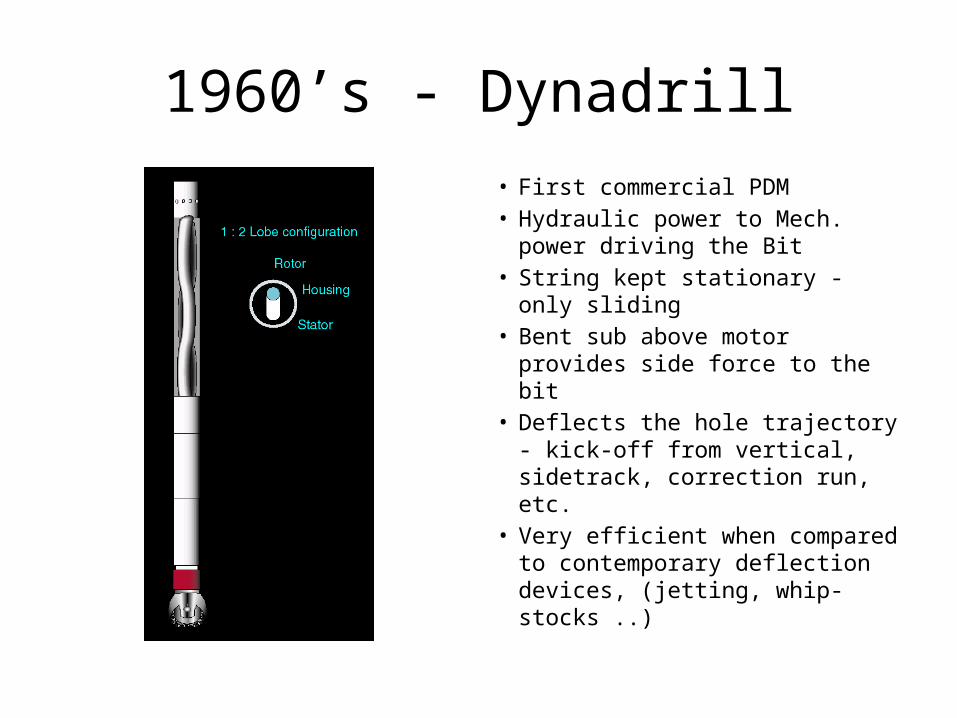
1960’s - Dynadrill• First commercial PDM• Hydraulic power to Mech.
power driving the Bit• String kept stationary - only
sliding• Bent sub above motor provides
side force to the bit• Deflects the hole trajectory -
kick-off from vertical, sidetrack, correction run, etc.
• Very efficient when compared to contemporary deflection devices, (jetting, whip-stocks ..)
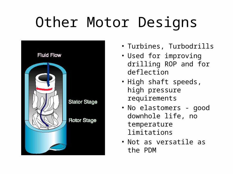
Other Motor Designs
• Turbines, Turbodrills• Used for improving drilling
ROP and for deflection• High shaft speeds, high
pressure requirements• No elastomers - good
downhole life, no temperature limitations
• Not as versatile as the PDM

Late 1980’s - Steerable Motors• Bend closer to the bit reduces bit
offset for equivalent curvature. – < bit offset = < component stress– Rotation possible without concern
for component failure.
• After kick-off, drill tangents, adjust trajectory without POOH. -Bit walk and build/drop tendencies not always predictable with rotary BHA’s.
• Efficiency achieved with motor bits, multi-lobe power sections and wireless MWD.
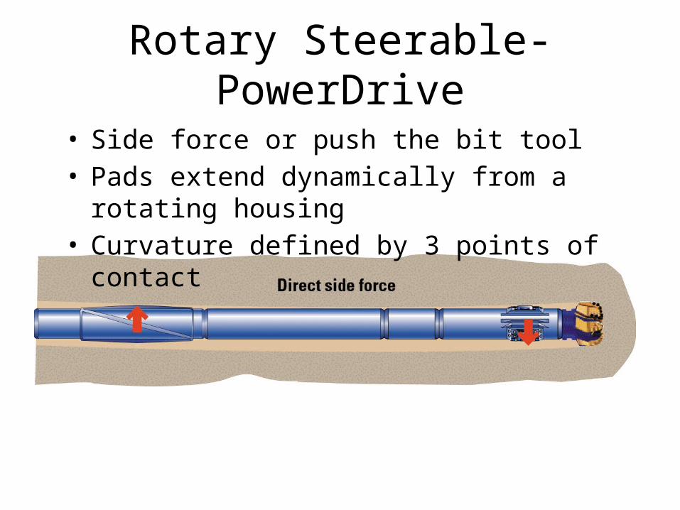
Rotary Steerable-PowerDrive
• Side force or push the bit tool• Pads extend dynamically from a rotating housing• Curvature defined by 3 points of contact
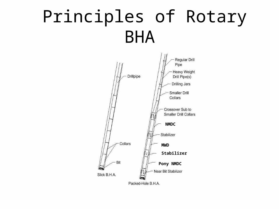
Principles of Rotary BHA
NMDC
MWD
Stabilizer
Pony NMDC
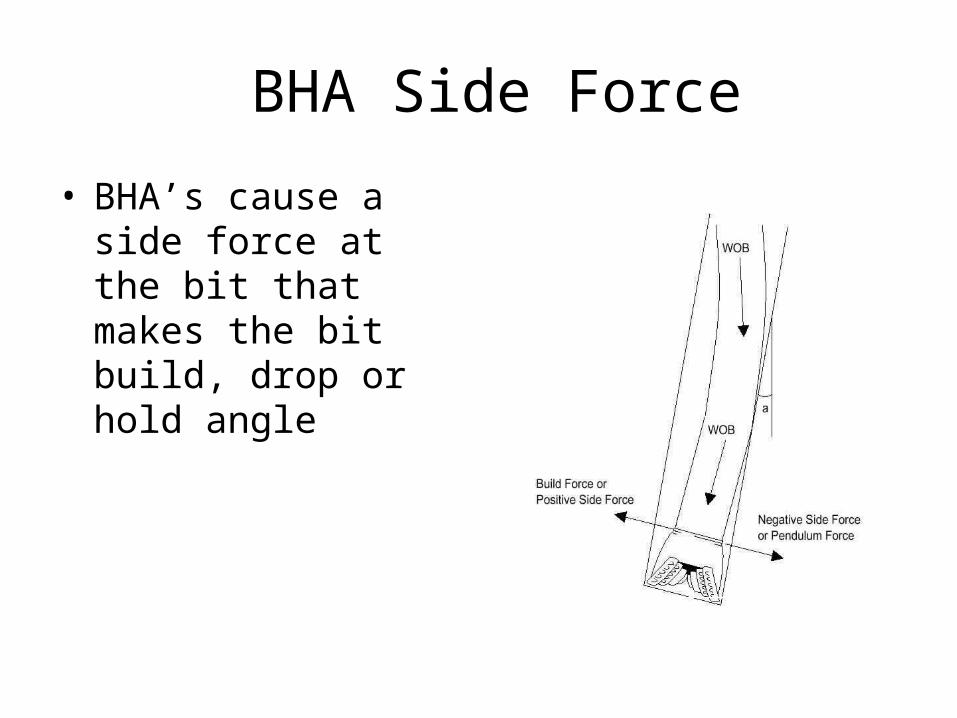
BHA Side Force
• BHA’s cause a side force at the bit that makes the bit build, drop or hold angle
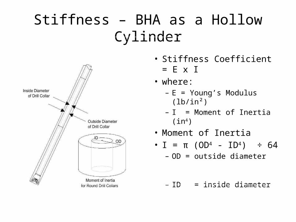
Stiffness – BHA as a Hollow Cylinder
• Stiffness Coefficient = E x I• where:
– E = Young’s Modulus (lb/in²)
– I = Moment of Inertia (in4)
• Moment of Inertia • I = π (OD4 - ID4) ÷ 64
– OD = outside diameter
– ID = inside diameter
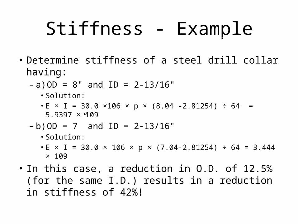
Stiffness - Example
• Determine stiffness of a steel drill collar having:– a) OD = 8" and ID = 2-13/16"
• Solution:• E × I = 30.0 ×10⁶ × p × (8.04 -2.81254) ÷ 64 = 5.9397 × 10⁹
– b) OD = 7” and ID = 2-13/16"• Solution:• E × I = 30.0 × 10⁶ × p × (7.04-2.81254) ÷ 64 = 3.444 × 10⁹
• In this case, a reduction in O.D. of 12.5% (for the same I.D.) results in a reduction in stiffness of 42%!
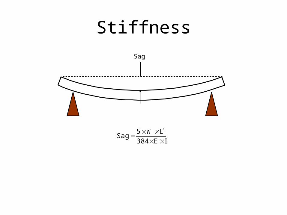
StiffnessSag
IE384
LW5Sag
4
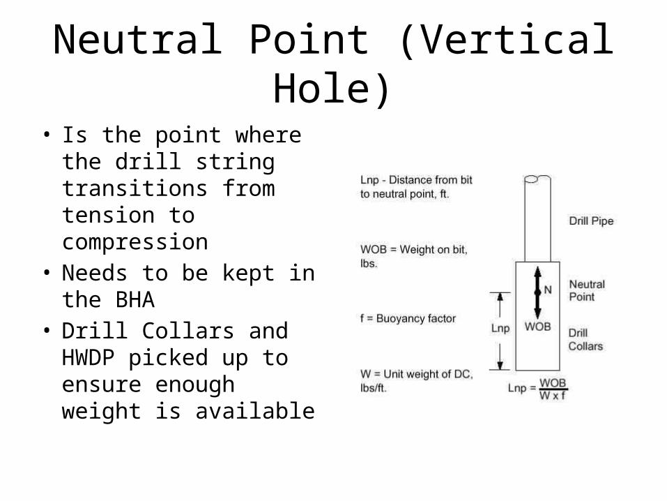
Neutral Point (Vertical Hole)
• Is the point where the drill string transitions from tension to compression
• Needs to be kept in the BHA
• Drill Collars and HWDP picked up to ensure enough weight is available
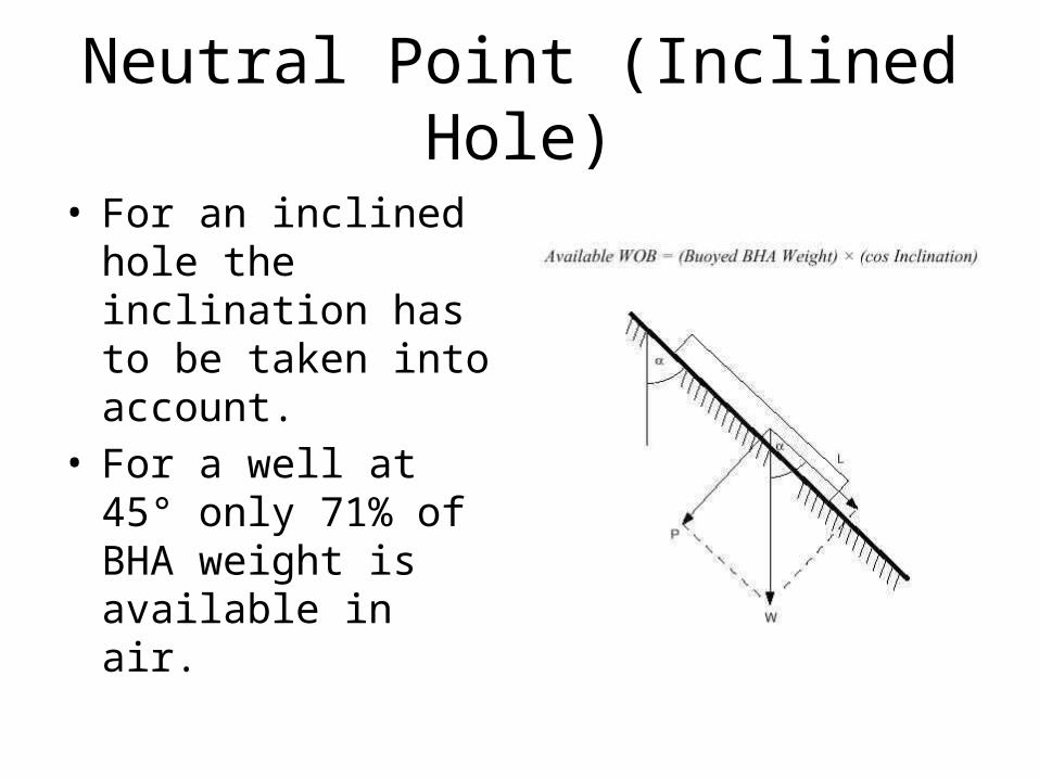
Neutral Point (Inclined Hole)
• For an inclined hole the inclination has to be taken into account.
• For a well at 45° only 71% of BHA weight is available in air.
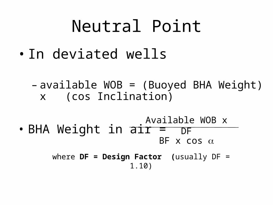
Neutral Point
• In deviated wells
– available WOB = (Buoyed BHA Weight) x (cos Inclination)
• BHA Weight in air = Available WOB x DF
BF x cos a
where DF = Design Factor (usually DF = 1.10)
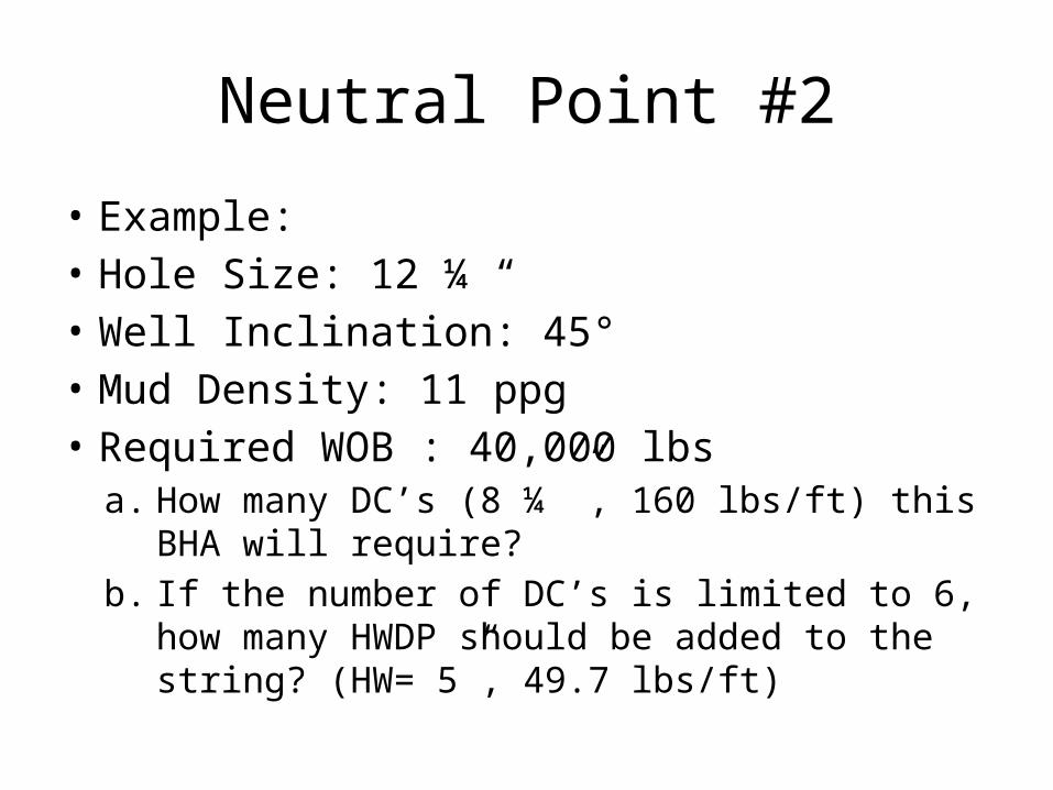
Neutral Point #2
• Example:• Hole Size: 12 ¼ “• Well Inclination: 45°• Mud Density: 11 ppg• Required WOB : 40,000 lbs
a. How many DC’s (8 ¼ ”, 160 lbs/ft) this BHA will require?
b. If the number of DC’s is limited to 6, how many HWDP should be added to the string? (HW= 5”, 49.7 lbs/ft)
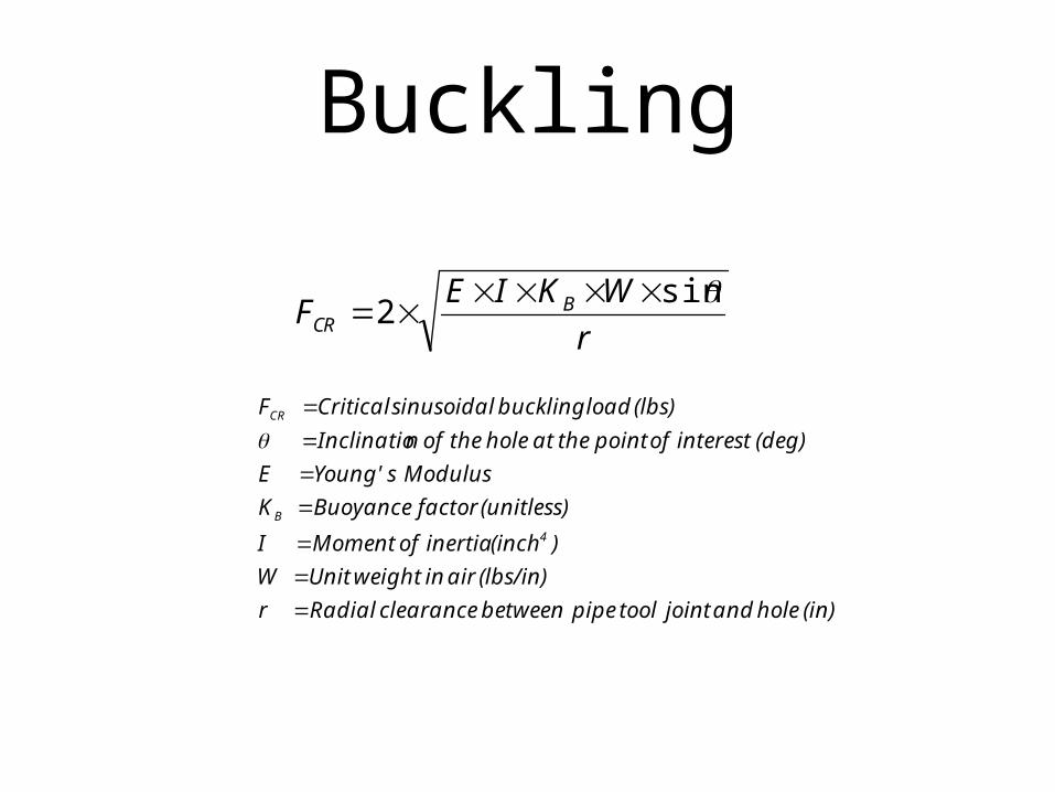
Buckling
r
WKIEF BCR
sin2
(in) hole and joint tool pipe between clearance Radial r
(lbs/in) air in weight Unit W
)(inch inertia of Moment I
(unitless) factor Buoyance K
Moduluss Young' E
(deg) interest of point the at hole the of nInclinatio
(lbs) load buckling sinusoidal Critical F
4
B
CR
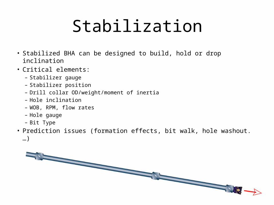
Stabilization• Stabilized BHA can be designed to build, hold or drop inclination • Critical elements:
– Stabilizer gauge– Stabilizer position– Drill collar OD/weight/moment of inertia– Hole inclination– WOB, RPM, flow rates– Hole gauge– Bit Type
• Prediction issues (formation effects, bit walk, hole washout.…)
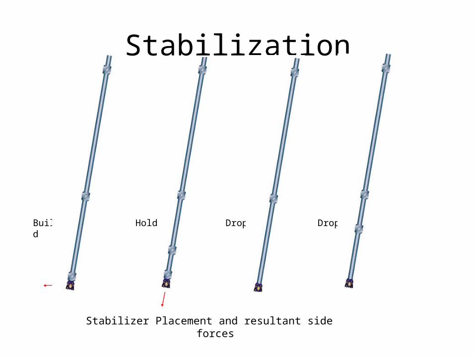
Stabilization
Build Hold Drop Drop
Stabilizer Placement and resultant side forces
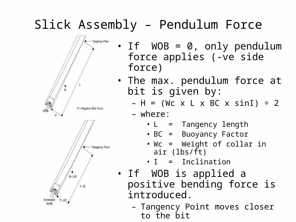
Slick Assembly – Pendulum Force• If WOB = 0, only pendulum force
applies (-ve side force)• The max. pendulum force at bit is
given by:– H = (Wc x L x BC x sinI) ÷ 2– where:
• L = Tangency length• BC = Buoyancy Factor• Wc = Weight of collar in air (lbs/ft)• I = Inclination
• If WOB is applied a positive bending force is introduced. – Tangency Point moves closer to the bit– And pendulum effect decreases
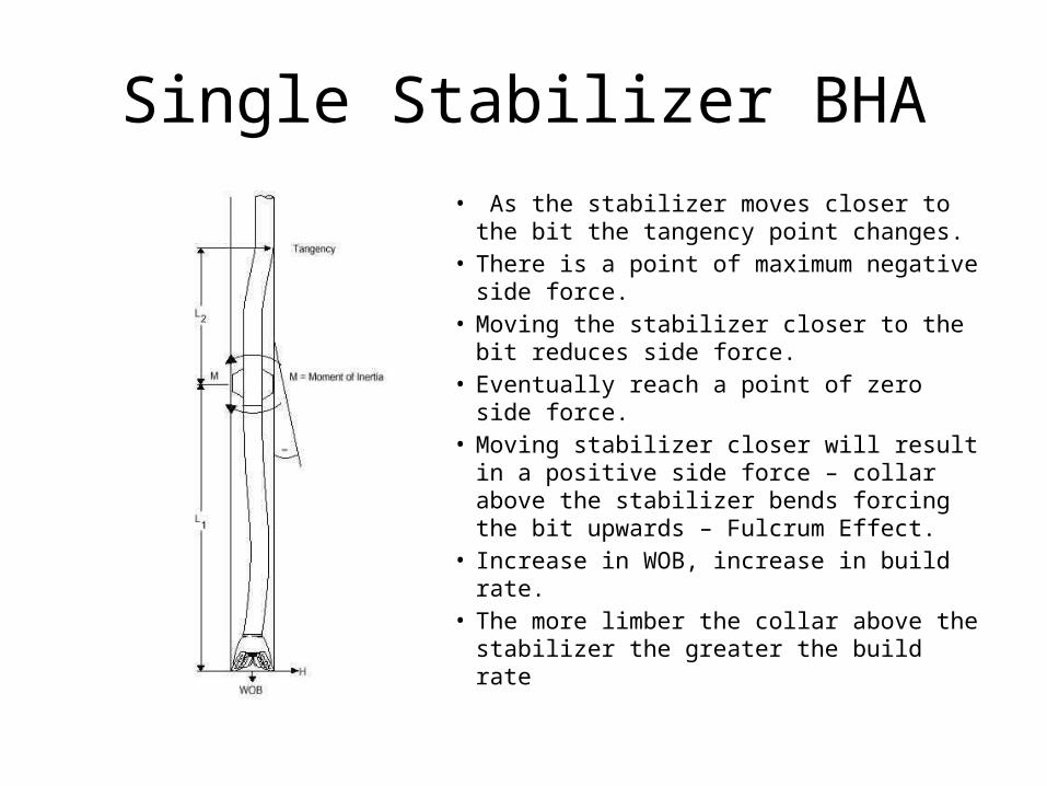
Single Stabilizer BHA• As the stabilizer moves closer to the bit
the tangency point changes.• There is a point of maximum negative side
force.• Moving the stabilizer closer to the bit
reduces side force.• Eventually reach a point of zero side force.• Moving stabilizer closer will result in a
positive side force – collar above the stabilizer bends forcing the bit upwards – Fulcrum Effect.
• Increase in WOB, increase in build rate.• The more limber the collar above the
stabilizer the greater the build rate
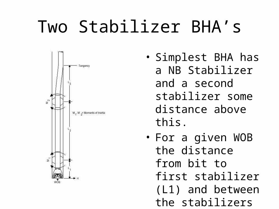
Two Stabilizer BHA’s
• Simplest BHA has a NB Stabilizer and a second stabilizer some distance above this.
• For a given WOB the distance from bit to first stabilizer (L1) and between the stabilizers (L2) determines the tangency point.
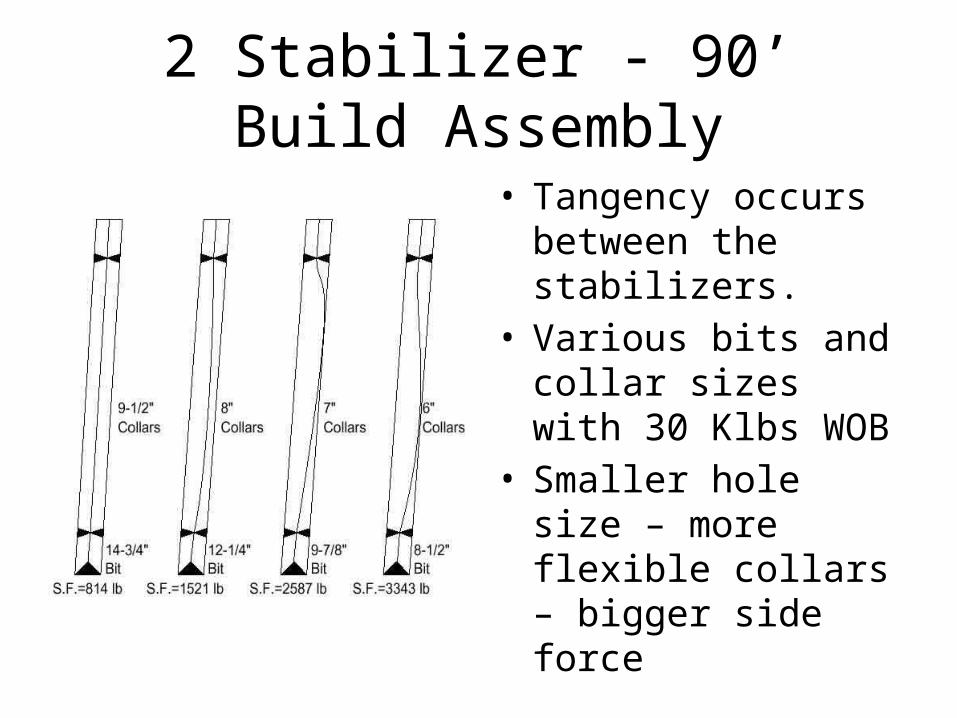
2 Stabilizer - 90’ Build Assembly
• Tangency occurs between the stabilizers.
• Various bits and collar sizes with 30 Klbs WOB
• Smaller hole size – more flexible collars – bigger side force

Effect of WOB
• What is the effect of increasing WOB?– to a building BHA– to a dropping BHA
• What are the limits?
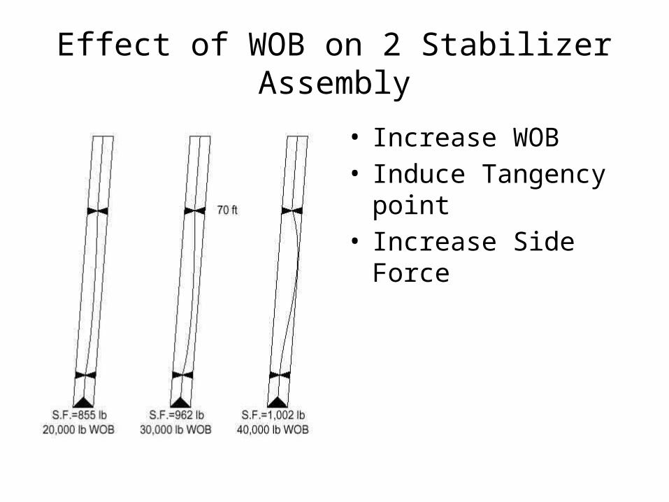
Effect of WOB on 2 Stabilizer Assembly
• Increase WOB• Induce Tangency point• Increase Side Force
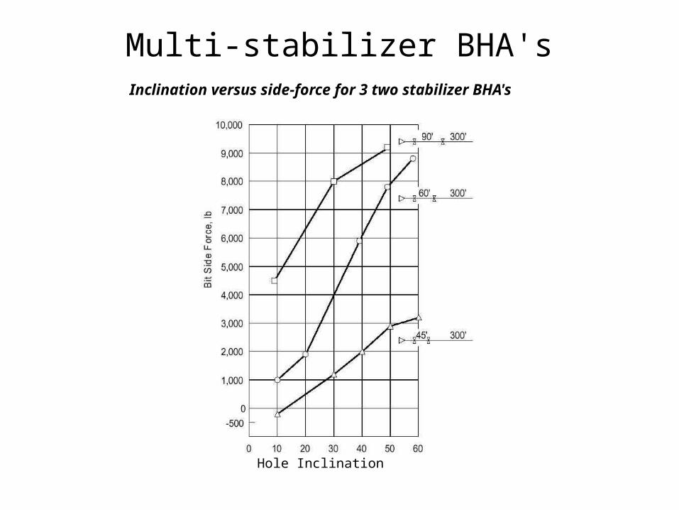
Multi-stabilizer BHA'sInclination versus side-force for 3 two stabilizer BHA's
Hole Inclination
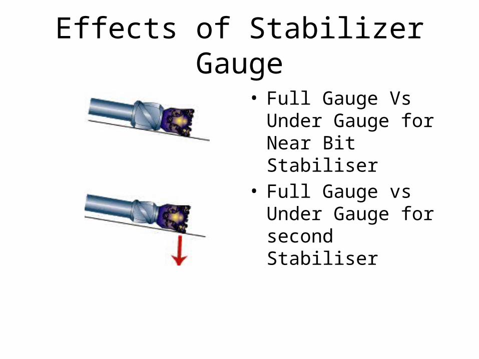
Effects of Stabilizer Gauge
• Full Gauge Vs Under Gauge for Near Bit Stabiliser
• Full Gauge vs Under Gauge for second Stabiliser
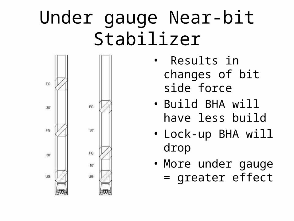
Under gauge Near-bit Stabilizer
• Results in changes of bit side force
• Build BHA will have less build
• Lock-up BHA will drop• More under gauge =
greater effect
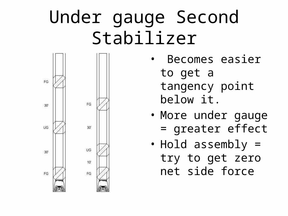
Under gauge Second Stabilizer
• Becomes easier to get a tangency point below it.
• More under gauge = greater effect
• Hold assembly = try to get zero net side force
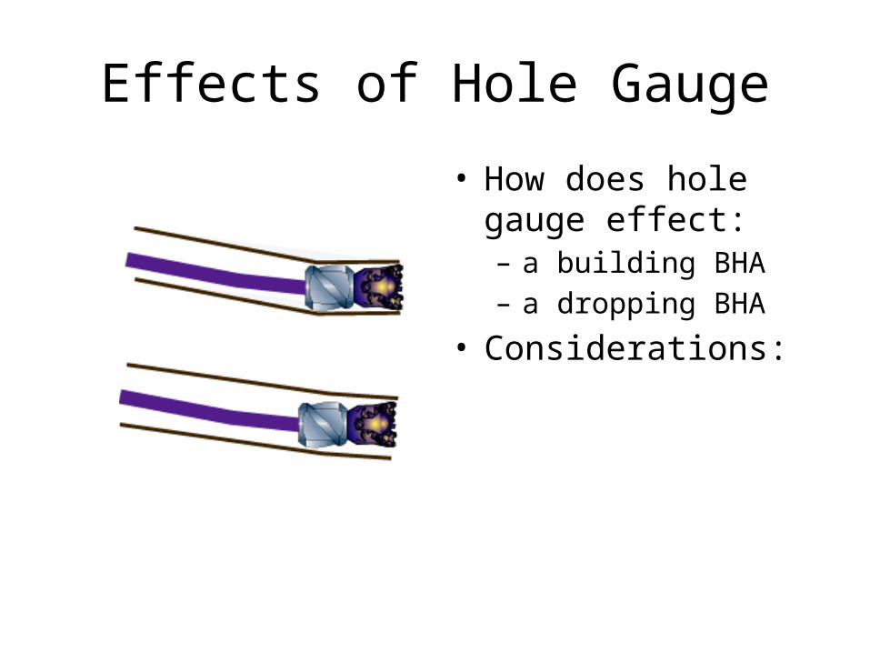
Effects of Hole Gauge
• How does hole gauge effect:– a building BHA– a dropping BHA
• Considerations:
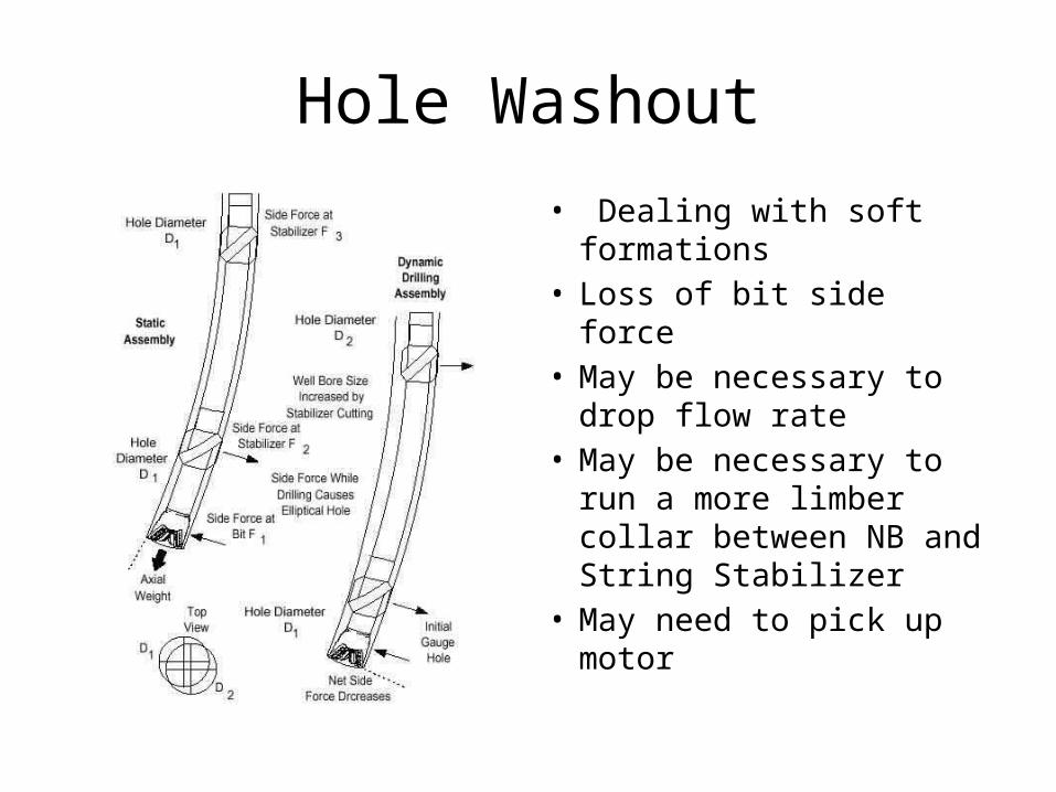
Hole Washout
• Dealing with soft formations
• Loss of bit side force• May be necessary to drop
flow rate• May be necessary to run a
more limber collar between NB and String Stabilizer
• May need to pick up motor
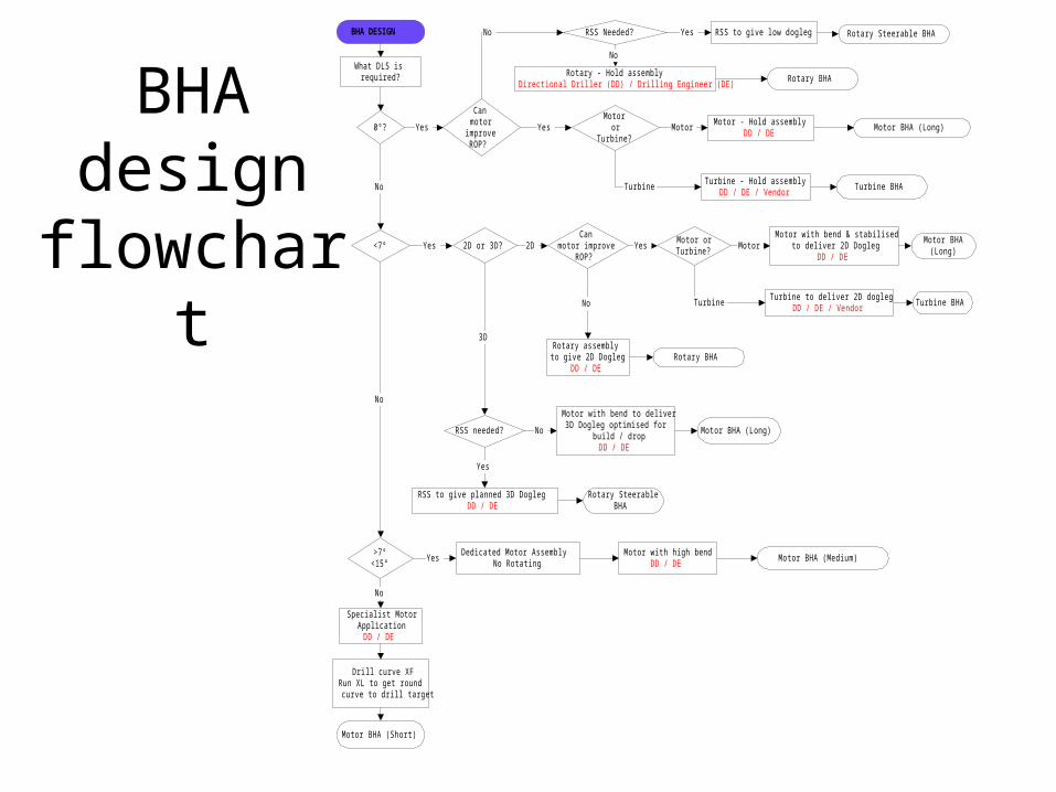
BHA design flowchart
What DLS isrequired?
0°?
Canmotor
improveROP?
Rotary - Hold assemblyDirectional Driller (DD) / Drilling Engineer (DE)
Rotary BHA
Motoror
Turbine?
Motor - Hold assemblyDD / DE
Motor BHA (Long)Motor
Turbine - Hold assemblyDD / DE / Vendor
Turbine BHATurbine
Yes
No
Yes
<7° 2D or 3D?Can
motor improveROP?
RSS needed?
3D
2DYes
RSS to give planned 3D DoglegDD / DE
Yes
Rotary SteerableBHA
Motor orTurbine?
YesMotor with bend & stabilised
to deliver 2D DoglegDD / DE
Motor Motor BHA
(Long)
>7°<15°
Dedicated Motor AssemblyNo Rotating
Motor with high bendDD / DE
Motor BHA (Medium)Yes
No
Specialist MotorApplication
DD / DE
Drill curve XFRun XL to get roundcurve to drill target
Motor BHA (Short)
No
No
Rotary assemblyto give 2D Dogleg
DD / DE
No
Rotary BHA
Motor with bend to deliver3D Dogleg optimised for
build / dropDD / DE
No Motor BHA (Long)
RSS Needed?
No
RSS to give low doglegYes Rotary Steerable BHA
Turbine to deliver 2D doglegDD / DE / Vendor
Turbine Turbine BHA
BHA DESIGN
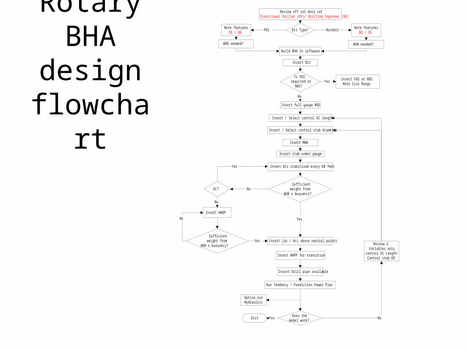
Rotary BHA design
flowchart
Review off set data setDirectional Driller (DD)/ Drilling Engineer (DE)
Bit Type?Note features
DD / DERockbit
Note featuresDD / DE
PDC
WOB needed? WOB needed?
Build BHA in software
Insert Bit
Is VGSrequired at
NBS?
Insert full gauge NBS
Insert / Select control DC length
Insert / Select control stab diameter
Insert MWD
Insert stab under gauge
Insert DCs stabilised every 60 feet
Sufficientweight from
WOB x buoyancy?
Insert jar / Acc above neutral points
Insert HWPP for transition
Insert Drill pipe available
No
Insert VGS at NBSNote Size Range
Yes
Yes
Yes
DC? No
Yes
No
Insert HWDP
Sufficientweight from
WOB x buoyancy?Yes
No
Review 2Variables only
control DC LengthControl stab OD
No
Run Tendency / Prediction Power Plan
Does themodel work?
Exit
Option runHydraulics
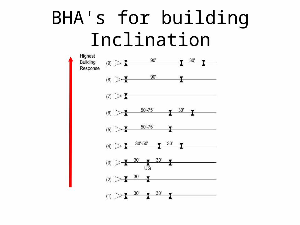
BHA's for building Inclination
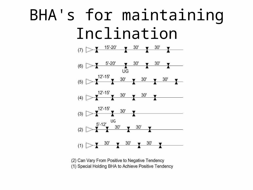
BHA's for maintaining Inclination
UG
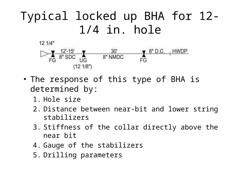
Typical locked up BHA for 12-1/4 in. hole
• The response of this type of BHA is determined by:1. Hole size2. Distance between near-bit and lower string stabilizers3. Stiffness of the collar directly above the near bit4. Gauge of the stabilizers5. Drilling parameters
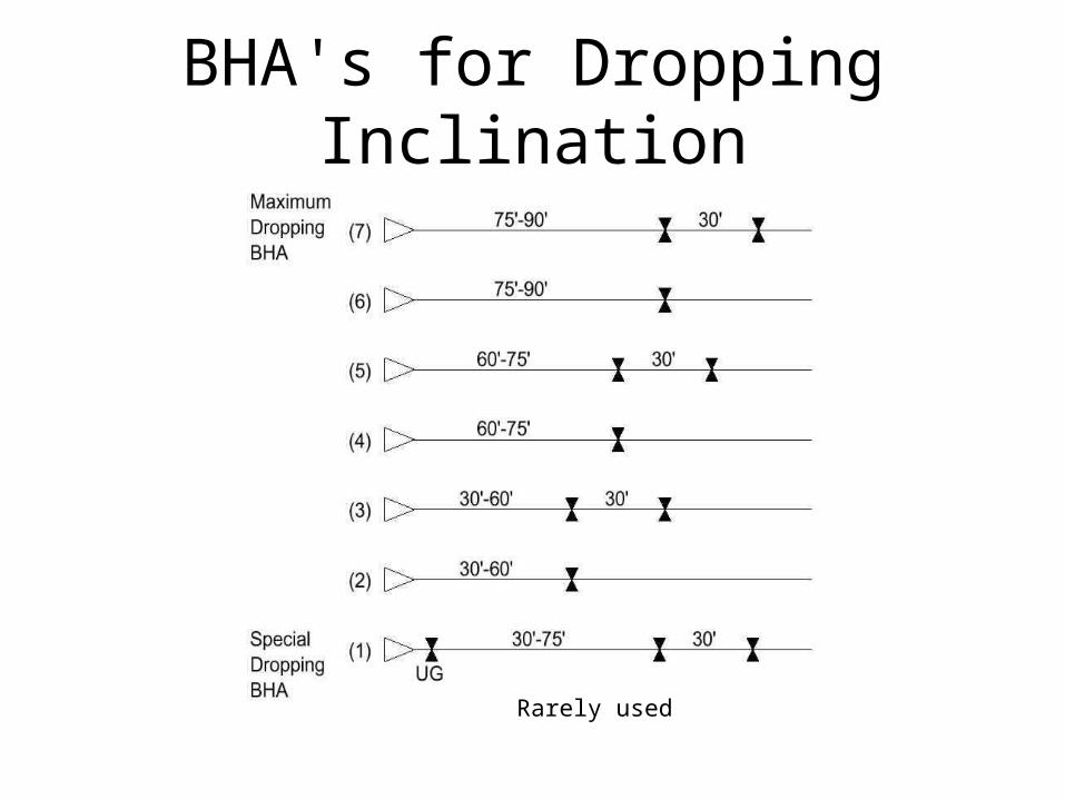
BHA's for Dropping Inclination
Rarely used
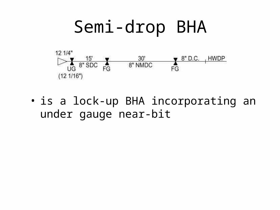
Semi-drop BHA
• is a lock-up BHA incorporating an under gauge near-bit
Special BHA's
• Tandem Stabilizer • Roller Reamers• Variable Gauge Stabilizer• Jetting BHA• Gilligan BHA's • Hole Openers

Tandem Stabilizers
• String Stabilizer run directly above near-bit• Normally for directional purposes• May result in high rotary torque• Longer gauge NB Stabilizer may be an
alternative
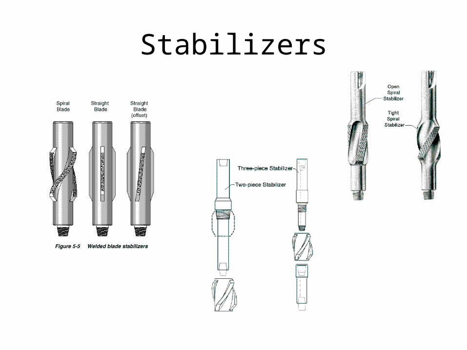
Stabilizers
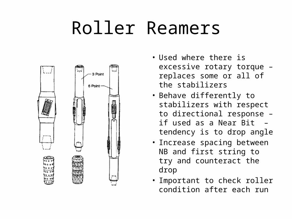
Roller Reamers• Used where there is excessive
rotary torque – replaces some or all of the stabilizers
• Behave differently to stabilizers with respect to directional response – if used as a Near Bit – tendency is to drop angle
• Increase spacing between NB and first string to try and counteract the drop
• Important to check roller condition after each run
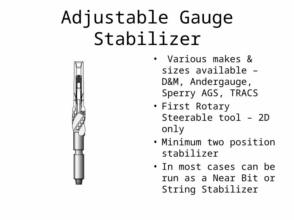
Adjustable Gauge Stabilizer
• Various makes & sizes available – D&M, Andergauge, Sperry AGS, TRACS
• First Rotary Steerable tool – 2D only
• Minimum two position stabilizer
• In most cases can be run as a Near Bit or String Stabilizer
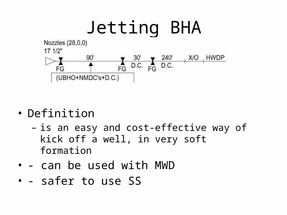
Jetting BHA
• Definition– is an easy and cost-effective way of kick off a well, in
very soft formation
• - can be used with MWD• - safer to use SS
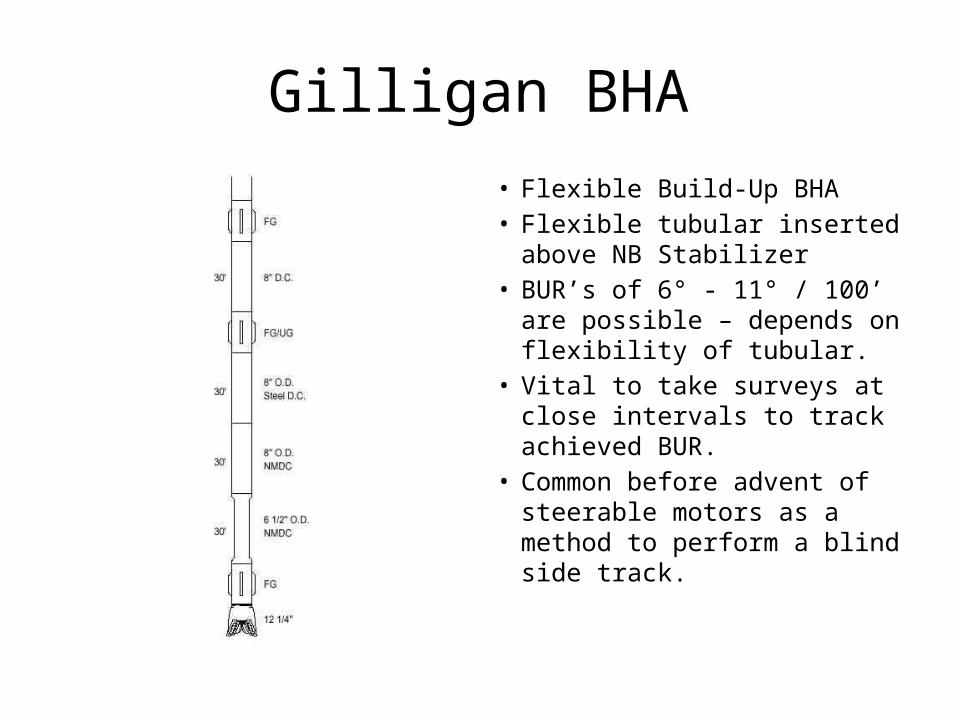
Gilligan BHA• Flexible Build-Up BHA• Flexible tubular inserted
above NB Stabilizer• BUR’s of 6° - 11° / 100’ are
possible – depends on flexibility of tubular.
• Vital to take surveys at close intervals to track achieved BUR.
• Common before advent of steerable motors as a method to perform a blind side track.
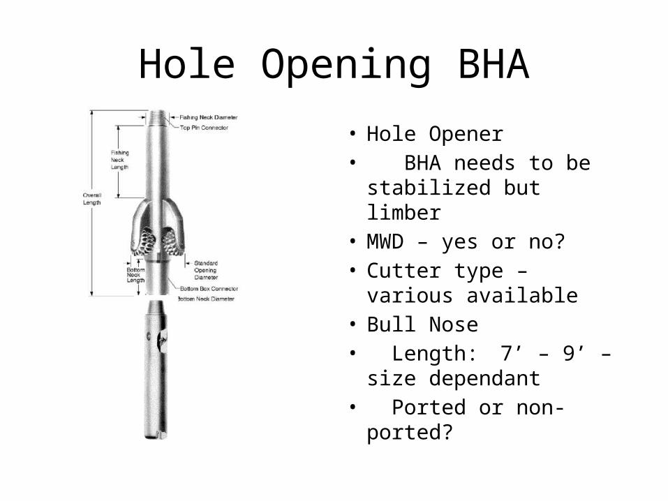
Hole Opening BHA
• Hole Opener• BHA needs to be
stabilized but limber• MWD – yes or no?• Cutter type – various
available• Bull Nose• Length: 7’ – 9’ – size
dependant• Ported or non-ported?
Common BHA Problems
• Formation Effects• Worn Bits• Accidental Side Track• Pinched Bit• Differential Sticking• Drilling Parameters
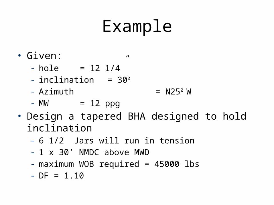
Example
• Given:- hole = 12 1/4” - inclination = 300 - Azimuth = N250 W- MW = 12 ppg
• Design a tapered BHA designed to hold inclination- 6 1/2” Jars will run in tension- 1 x 30’ NMDC above MWD- maximum WOB required = 45000 lbs- DF = 1.10
Example
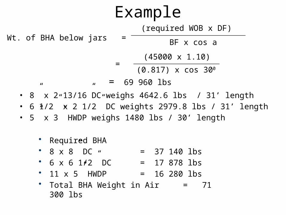
• 8” x 2 13/16”DC weighs 4642.6 lbs / 31’ length• 6 1/2” x 2 1/2” DC weights 2979.8 lbs / 31’ length• 5” x 3” HWDP weighs 1480 lbs / 30’ length
Wt. of BHA below jars =(required WOB x DF)
BF x cos a
• Required BHA• 8 x 8” DC = 37 140 lbs• 6 x 6 1/2” DC = 17 878 lbs• 11 x 5” HWDP = 16 280 lbs• Total BHA Weight in Air = 71 300 lbs
(45000 x 1.10)
(0.817) x cos 300=
= 69 960 lbs