Embed Size (px)
Citation preview

Original Instructions Air Handing Units
Installation, Operations and Maintenance Manual
2019 Release
ECE UK LTD Pharaoh House, Arnolde Close, Rochester, Kent. ME2 4QW
Rotary Exchanger Aluminium 3-Way Mix RXA3MX

IOM
Installation, Operation and Maintenance
for ECE air handling and conditioning units
Table of Contents 1
Table of Contents
Table of Contents ................................................................................................................................................................................................................... 1
Purpose ................................................................................................................................................................................................................................. 3
Checks at Design Stage ........................................................................................................................................................................................................ 4
Air Inlets and Discharges .................................................................................................................................................................................................. 5
Acoustics - Vibration ......................................................................................................................................................................................................... 7
Services - Connections ..................................................................................................................................................................................................... 7
Commissioning & Fault Finding ........................................................................................................................................................................................ 7
Maintenance Repair and Renewal .................................................................................................................................................................................... 8
General ............................................................................................................................................................................................................................. 8
Checks at Order Stage .......................................................................................................................................................................................................... 9
General Information ........................................................................................................................................................................................................ 10
Contract Information ....................................................................................................................................................................................................... 10
Unit Information .............................................................................................................................................................................................................. 10
External System Resistance ............................................................................................................................................................................................ 10
Drives .............................................................................................................................................................................................................................. 10
Filters .............................................................................................................................................................................................................................. 10
Inlets and Discharges ..................................................................................................................................................................................................... 10
Separation / Mixing Boxes / VCDs .................................................................................................................................................................................. 10
Volume Control ............................................................................................................................................................................................................... 10
Heating / Cooling ............................................................................................................................................................................................................ 10
Plenums .......................................................................................................................................................................................................................... 10
Inlet / Discharges ............................................................................................................................................................................................................ 10
Vibration Isolators ........................................................................................................................................................................................................... 10
Flexibles .......................................................................................................................................................................................................................... 10
Attenuators ..................................................................................................................................................................................................................... 10
Ancillaries ........................................................................................................................................................................................................................ 11
Construction ................................................................................................................................................................................................................... 11
Finish .............................................................................................................................................................................................................................. 11
Protection ........................................................................................................................................................................................................................ 11
Site Costs........................................................................................................................................................................................................................ 11
Problems......................................................................................................................................................................................................................... 11
Delivery ................................................................................................................................................................................................................................ 12
Receipt & Unpacking ...................................................................................................................................................................................................... 13
Lifting .............................................................................................................................................................................................................................. 14
Crane - Long lifting straps - 150mm min. width ......................................................................................................................................................... 14
Crane – “H Frame” Short lifting straps - 150mm min. width ...................................................................................................................................... 14
Fork lift ....................................................................................................................................................................................................................... 15
Moving ............................................................................................................................................................................................................................ 15
Rollers ........................................................................................................................................................................................................................ 15
Skates ........................................................................................................................................................................................................................ 15
Toe Jacks .................................................................................................................................................................................................................. 16
Installation ............................................................................................................................................................................................................................ 17
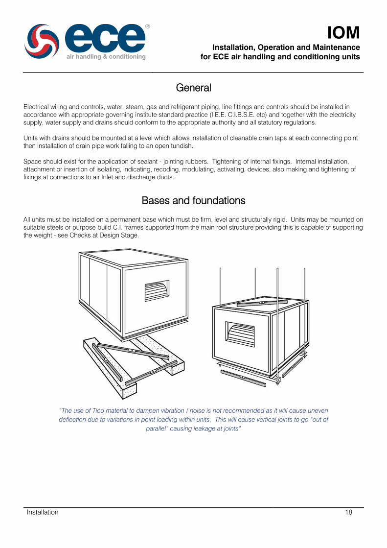
General ........................................................................................................................................................................................................................... 18
Bases and foundations ................................................................................................................................................................................................... 18
Plug Fans ........................................................................................................................................................................................................................ 20
Fitting the Accessories .............................................................................................................................................................................................. 20
Electrical Connections ............................................................................................................................................................................................... 20
Rotary Exchanger Aluminium .......................................................................................................................................................................................... 21
Transport ................................................................................................................................................................................................................... 21
Mechanical installation .............................................................................................................................................................................................. 22
Hydraulic Connection ................................................................................................................................................................................................ 23
Installation of sensors ................................................................................................................................................................................................ 23
Electrical installation .................................................................................................................................................................................................. 23
Assembly of segmented rotary heat exchangers ...................................................................................................................................................... 23

IOM
Installation, Operation and Maintenance
for ECE air handling and conditioning units
Table of Contents 2
Storage ...................................................................................................................................................................................................................... 23
Commissioning .................................................................................................................................................................................................................... 24
SISW / DIDW Fans - Motors – Drives .............................................................................................................................................................................. 25
Belt Drives .................................................................................................................................................................................................................. 25
Anti-Vibration Mountings ............................................................................................................................................................................................ 27
Checking Label Positioning ............................................................................................................................................................................................ 27
Servicing Filters ............................................................................................................................................................................................................... 28
Mixing Boxes - Separation Boxes - Shut off VCD’s - HRD’s ........................................................................................................................................... 30
Coils ................................................................................................................................................................................................................................ 30
Coil Connections ....................................................................................................................................................................................................... 31
Setting Water Flow through Coils .............................................................................................................................................................................. 31
Coil Condensate Drains ............................................................................................................................................................................................. 32
Draw Through Units and Blow Through Units with negative pressure (depression at trap) .................................................................................. 32
Blow through units with positive pressure at trap .................................................................................................................................................. 33
Coil Condensate Faults ............................................................................................................................................................................................. 34
Draw Through ........................................................................................................................................................................................................ 34
Blow Through ........................................................................................................................................................................................................ 35
Draw through coils with condensate pump ........................................................................................................................................................... 36
DX Cooling Coils........................................................................................................................................................................................................ 37
Chilled Water Cooling and LP Hot Water Heating Coils ............................................................................................................................................ 38
Guidelines for water circuits in C.W. Coolers and LPHW Heaters ......................................................................................................................... 38
Bypass Circuit .................................................................................................................................................................................................. 38
Mixing circuit using three-way mixing valves. ................................................................................................................................................... 38
Chilled Water Cooling Coils ................................................................................................................................................................................... 39
Hot Water Heating Coils ........................................................................................................................................................................................ 40
Steam Coils ............................................................................................................................................................................................................... 41
Electric Heater Batteries ................................................................................................................................................................................................. 43
Gas Fired Heaters ........................................................................................................................................................................................................... 44
Electronic Steam Humidifiers .......................................................................................................................................................................................... 45
Rotary Exchanger ........................................................................................................................................................................................................... 46
Maintenance ........................................................................................................................................................................................................................ 47
Maintenance Schedule ................................................................................................................................................................................................... 48
Maintenance Action (not already indicated in Schedule) ................................................................................................................................................ 50
Plug Fans - Replacing the Motor and the Impeller .................................................................................................................................................... 50
SISW / DIDW - Fan Bearings ..................................................................................................................................................................................... 54
Spider Arm Bearing ............................................................................................................................................................................................... 54
Plummer Block Bearing ......................................................................................................................................................................................... 55
Direct Drive Fans ................................................................................................................................................................................................... 56
Replacing the filters (for HTM specification units) ..................................................................................................................................................... 56
Motor Bearings .......................................................................................................................................................................................................... 58
Motors without Grease Points .................................................................................................................................................................................... 58
Motor Overheating ..................................................................................................................................................................................................... 59
Washable Filters ........................................................................................................................................................................................................ 59
Autoroll Filters ............................................................................................................................................................................................................ 59
Activated Carbon (Constantly Monitored).................................................................................................................................................................. 59
Activated Carbon (disposable non-monitored).......................................................................................................................................................... 59
Electric Heater Batteries ............................................................................................................................................................................................ 59
Dampers - Motors ...................................................................................................................................................................................................... 59
Coils - General ........................................................................................................................................................................................................... 59
DX Cooling Coils........................................................................................................................................................................................................ 59
Rotary Exchangers .................................................................................................................................................................................................... 60
Fault Finding ........................................................................................................................................................................................................................ 61
Centrifugal Fans.............................................................................................................................................................................................................. 62
Electric Heaters ............................................................................................................................................................................................................... 63
Cooling Coils .................................................................................................................................................................................................................. 63
Heating Coils .................................................................................................................................................................................................................. 65

IOM
Installation, Operation and Maintenance
for ECE air handling and conditioning units
Purpose 3
Refrigeration ................................................................................................................................................................................................................... 65
Fan Drive Belts ................................................................................................................................................................................................................ 66
Purpose
This manual contains advice for installers and users.
General information about the range, construction and selection of ECE air handling/conditioning equipment can be
obtained from our website, various sales publications, or by telephone.
Certified individual unit data concerning dimensions, weights, component specification and performance, is issued with
the order acknowledgement for each unit.
Due to our policy of continuous improvement the information contained within this Manual may be altered from time to
time without prior notice.

IOM
Installation, Operation and Maintenance
for ECE air handling and conditioning units
Checks at Design Stage 4
Checks at Design Stage

IOM
Installation, Operation and Maintenance
for ECE air handling and conditioning units
Checks at Design Stage 5
Air Inlets and Discharges
Whether ducted, or part of the Air Handling Unit, inlet and discharge connections to atmosphere such as Louvres, Cowls,
Spigots, etc. should be located and dimensioned so that the flow restriction, short circulating, recirculation of vitiated air,
pick up of contaminated air or nuisance discharge of exhaust air do not occur.
Ducted intakes and discharges to units should be designed and constructed to ensure that flow restriction, turbulence,
pre rotation, jetting, uneven velocity profile and surface or object excitation do not occur.
Poor intake design causes uneven velocity profile across unit components resulting in moisture carryover hence flooding,
design supply air conditions not being achieved, electric heater elements overheating, DX refrigerant cooling coils
freezing and secondary generation of noise and vibration etc.
A.S. SCTV = Aerofoil Section Short Cord Turning Vane 50mm ctrs.
LCTV = Long Cord Turning Vanes to HEVAC – CIBSE – ASHRAE Standards

IOM
Installation, Operation and Maintenance
for ECE air handling and conditioning units
Checks at Design Stage 6
Poor discharge design causes reduction in fan pressure and volume, also turbulence generating secondary noise and
vibration, which may reduce impeller, bearing, isolator and flexible connection life. Design supply conditions may also be
achieved. Electric elements may overheat. DX coils may freeze.
A.S. SCTV = Aerofoil Section Short Cord Turning Vane 50mm ctrs.
D = Fan inlet eye diameter
LCTV = Long Cord Turning Vanes to HEVAC – CIBSE – ASHRAE Standards

IOM
Installation, Operation and Maintenance
for ECE air handling and conditioning units
Checks at Design Stage 7
Acoustics - Vibration
Ensure space exists for incorporating attenuation of the noise to atmosphere from outside air inlet and exhaust air
discharge and on room side supply and extract ducts.
Consider noise from casing radiation, flanking and breakout.
Consider primary and secondary vibration isolation including service connections.
Services - Connections
Ensure space with clearance exists for access to, routing of, connection to and expansion and contraction of water,
steam, refrigerant, gas oil supplies and line fittings. Combustion air supply, flue gas exhaust. Venting of air, isolating and
draining of plant, trapping and returning steam, condensate, trapping and draining of condense from cooling coils,
humidifiers and heat recovery devices to open tundish, blowing down waste to open tundish, pumping down and storing
of refrigerant, power – control wiring, and components.
Commissioning & Fault Finding
Ensure plant is designed to allow installation of and access to calibration and adjustment of measuring and modulating
devices for:
Air flow direction and rate
Medium flow direction and rate
Resistance to airflow
Resistance to medium flow
Air on and off dry bulb, wet bulb and humidity
Medium on and off pressure and temperature
Ensure space exists in and around the plant for access to, inspection of, measuring of and work on items including:
Belt tensioning of external motors
Jacking and levelling of steel spring vibration isolators
Clear sight of identifying labels measuring and recording devices
VCD blades, links and actuators, humidifier generators, sparge pipes, coil and eliminator surfaces and drain
pans, electric heaters, fan and drives
Fan speed and direction of rotation
Motor current, resistance, continuity
Motor nameplate
Terminal wiring diagrams
Wiring

IOM
Installation, Operation and Maintenance
for ECE air handling and conditioning units
Checks at Design Stage 8
Maintenance Repair and Renewal
For units with one piece coils ensure space exists of at least one unit width plus 150mm on the withdrawal side of each
plant item. For units with split coils ensure at least half the width of the unit or 700mm whichever is greater.
Adjacent units can share the common space between them for access and withdrawal.
Ensure room exists for safe working platforms where units are mounted at high level.
Ensure provision exists for steps, ladders etc. Where units are over 1750mm high or mounted on platforms which elevate
the unit height and make access difficult.
General
Any or all of the following and their effect on the plant should be considered and the appropriate action taken:
Conditions within surrounding areas
External temperature and humidity
Direct solar radiation
Wind speed and direction
Driven rain
Driven snow
Driven sand
Sea spray, mist, fog, moisture in suspension
Saline atmosphere
Icing
Unit surface temperatures and surrounding air dew point
Gases which form acids in solution in water, such as SO²
Flammability
Explosion risk
Toxicity
Bacteria
Fungi
Algae

IOM
Installation, Operation and Maintenance
for ECE air handling and conditioning units
Checks at Order Stage 9
Checks at Order Stage

IOM
Installation, Operation and Maintenance
for ECE air handling and conditioning units
Checks at Order Stage 10
General Information
Date
Time
Contact(s)
Company
Address
Phone Number
Fax Number
Email Address
Contract Information
Customer Ref. No.
Confidential? Job Name
Delivery Area
Specification Pages
Other Standards Referred To In Spec
Drawing No’s.
Schedule Reference
Other Customer Documents
Unit Information
Item No
Area Ref
Supply / Extract
Int / Ext / Roof / Fitted Works or Site
Part / Horiz
Part / Vert
Configuration / Sketch
25mm - 50mm Panels
External System Resistance
Depression at Unit Inlet
Positive at Fan Discharge
Pressurised Sep / Mix
Box / Plenum
Diffusion / Blanking Screen?
One-Two-Duplex-Triplex
DIDW - SISW
FC / BC
BD / DD
Raft / Rigid
I.G.V. + Controller
NRD’s One. Two.
Guards:
Inlet / Eyes / Disch / Drive
Drives
Motors Int / Ext
Duty / Idling
Pulleys / Belts / In / Out / Air Stream
1 Speed / 2 Speed / Variable Speed
Spd Change Interlock with EAHB.
Pole Change/Dual Wound.
Electromagnetic Clutch (TASC)
Switched Reluctance
Inverter
DOL / SD
St’ D/Flf
Elec Supply
Floor Grid
Lifting Beams
Filters
Presti.Stii
St.I. 11.111.
To Extract Heat Recovery
Grease to Kitchen Extract
Type
Efficiency by Weight
Efficiency Spot Dust
Retentivity (Act. Carbon)
BS. ASHRAE. Eurovent
Withdrawal - Side / US / DS / T / B
Fitted Manometer(s)
Magnehelic(s)
Radiant Heat from EAHB
Inlets and Discharges
Louvres / FAI / DTA / Std / Acoustic
Elmtrs + Drain High Velocity
Fan Discharge 45º Spigot + Mesh
Separation / Mixing Boxes /
VCDs
Int / Ext Dampers
FAI / RC / DTA Position
Opp / Par / Man / Motor Belimo
Volume Control
100% / Zone / F&BP / Location
Int / Ext.
Opp / Par / Man / Motor
Construction GSS
Heating / Cooling
Heat Recovery
Heat Rejection
Dehumidifying
Humidifying
Positon / Type
Draw Through / Blow Through
Volume M3/s
Air On Cwb / Deb / Kg / Kg
Air Off Cwb / Db / Kg / Kg
Sweating Ins Frame
Dx +Const Off = Freeze
Humid Posn Adj Surfaces - Wetting
Clear Distance Downstream
Gas Heater. Condensation - Bypass
Combst’n Air Inlet - Flue Output. Posn
Load / Eff / Output
Steps / Interplaced / Face
Medium Type
Flow Return ºc
Evap. Temp. ºc
Pressure – Bar / Kpa
Glycol %
Outside Ambient
Cond. Temp. C
Elec Supply
EAHB Min Air Flow Speed
EAHB Balanced Across 3ph Supply
Interlock With Var.Sp.Fan.
Construction
Plates / Tubes / Fins
Elements / Burner / Infill
Finish: Self / Vinyl / Et.
Free Cooling & Mechanical Top Up.
Air Entering At 90º to Coil Face.
Face Velocity Profile
Condensate Drain Provision - Height
Plenums
Location / Function
Diffuser / Spacer / Access
90º / Horz / Vert
To / From: Above / Below / LHS / RHS
Hinged / Lift Off.
Tool Op / Handles / Lock To One Handle
Viewport(s)
Bulkhead Light(s) Ext Switch
Wiring by Others
Floor Grids
Inlet / Discharges
From: Above / Below / LHS / RHS / Face
Louvre / Spigot
Stack & Cowl
90º + Sctv
Grill / SD / DD / NV / OBDs
Construction
Finish
Vibration Isolators
Int / Ext
Eff Required %
Rubber in Shear / Steel Spring
Jacking
Self-Levelling
Fixed/Loose
Flexibles
Isolating / Fan Raft / Fan Section
Compute Unit / Pipe Connections
Attenuating
Flame Resistant
Construction
Finish
Breakout
Flanking
Attenuators
Extract / Atmos / Room Side / Zone
Supply / Atmos / Room Side / Zone
To Achieve NR In / At
Unit/Duct Mounted
Straight /90 + SCTV
Volume m3/s
Inlet / Outlet Plenum / Length
From / To / Above / Below / LHS / RHS /
Face
Finish
Breakout
Flanking

IOM
Installation, Operation and Maintenance
for ECE air handling and conditioning units
Checks at Order Stage 11
Ancillaries
50 x 100 x 50 Full Perimeter Base
6mm Anodised Aluminium
3mm GSS
Integral Lugs
Support Legs
Support Steelwork
Side / Central Services Corridors
Pipework
Controls
Wiring
Access Platforms
Construction
Frame / GSS / Ali / Plastisol
Outer Panels / GSS / Plastisol
Inner Skin / GSS / Plastisol St. St.
Insulation 20mm / 50mm / 65kg / m3
Finish
Location Ext / Int
Anodised All
Plastisol
GSS Self
Protection
Polystyrene Corners
Cling Film Wrap
Polystyrene Boards
Rewrapped after Assembly
Site Costs
Site Supervision Work Required
Site Assembly Required
Safety Checks I.E. Gas Heaters
Guarantee Checks
I.E. Assembly Standards, Weathering and
Site Air Leakage Standards
Problems
Transport: Loaded Vehicle Obstacle
Clearance / Route Load Bearing
Road Closure / Stat Permissions
Onloading / Off Loading
Crane, Fork Lift Weight / Capacity
Moving On Site: Route / Loads / Method
Building Load Bearing
Max Size / Weight per Piece for Access
Dry Storage before Erection
Bases: Level / Load Brg / Relevelling
Dev’s
Bolting Adjacent Sections Onsite
I.E. Heating & Cooling Coils
Access / Maintenance / Withdrawal Plant
Sun / Wind / Rain / Snow
Saline / Icing
Dust / Powder / Grit / Soot / Smoke / Sand
Tall Units on Plinths Side Walkway?
Are Top Access Door Catches In Reach?
Containment & Drainage of Leaks
Sloping, Differential Trapped
Condense Drains, To Open Tundish
Miswiring Motors Competent Electrician

IOM
Installation, Operation and Maintenance
for ECE air handling and conditioning units
Delivery 12
Delivery

IOM
Installation, Operation and Maintenance
for ECE air handling and conditioning units
Delivery 13
Receipt & Unpacking
Units are designed and manufactured according to ISO 9001
As part of our quality control system each unit undergoes a full pre-delivery inspection before loading.
Units are then fitted with corner protection and wrapped in polythene to prevent ingress of foreign bodies or water during
transportation.
All units are fitted with a full perimeter bases to facilitate lifting, moving and installation.
Unit wrapped ready for dispatch
Units should be inspected and any external damage or short delivery reported to ECE, before unloading.
We cannot accept responsibility for damage sustained during unloading from the delivery vehicle or on site.
Units must be off loaded, lifted and lowered using long lifting straps and timber blocks or using an “H” Frame with short
lifting straps and timber blocks or a fork lift with extended forks.
Final lowering and side shifting to bring parallel faces together should be by toe jacks with timber blocks.
Internal joining bolts should never to be used to pull modules together.
Modules should never be rolled over to more across site.
Guidance notes for unloading and handling are given in the following pages.
Before commissioning all packaging materials must be removed from the units and cleared from the area.

IOM
Installation, Operation and Maintenance
for ECE air handling and conditioning units
Delivery 14
Lifting
Crane - Long lifting straps - 150mm min. width
Crane – “H Frame” Short lifting straps - 150mm min. width

IOM
Installation, Operation and Maintenance
for ECE air handling and conditioning units
Delivery 15
Fork lift
Moving
Rollers
Skates

IOM
Installation, Operation and Maintenance
for ECE air handling and conditioning units
Delivery 16
Toe Jacks

IOM
Installation, Operation and Maintenance
for ECE air handling and conditioning units
Installation 17
Installation
IOM
Installation, Operation and Maintenance
for ECE air handling and conditioning units
Installation 18
General
Electrical wiring and controls, water, steam, gas and refrigerant piping, line fittings and controls should be installed in
accordance with appropriate governing institute standard practice (I.E.E. C.I.B.S.E. etc) and together with the electricity
supply, water supply and drains should conform to the appropriate authority and all statutory regulations.
Units with drains should be mounted at a level which allows installation of cleanable drain taps at each connecting point
then installation of drain pipe work falling to an open tundish.
Space should exist for the application of sealant - jointing rubbers. Tightening of internal fixings. Internal installation,
attachment or insertion of isolating, indicating, recoding, modulating, activating, devices, also making and tightening of
fixings at connections to air Inlet and discharge ducts.
Bases and foundations
All units must be installed on a permanent base which must be firm, level and structurally rigid. Units may be mounted on
suitable steels or purpose build C.I. frames supported from the main roof structure providing this is capable of supporting
the weight - see Checks at Design Stage.
“The use of Tico material to dampen vibration / noise is not recommended as it will cause uneven
deflection due to variations in point loading within units. This will cause vertical joints to go “out of
parallel” causing leakage at joints”

IOM
Installation, Operation and Maintenance
for ECE air handling and conditioning units
Installation 19
When foundations are uneven units will “lozenge” if the installer attempts to use the joining bolts to pull non parallel faces
together causing air leakage at joins, access doors will jam and not close after opening and duct connections will not be
“parallel” and will leak.
Elevation Plan
When foundations are level and perfectly flat units will be perfect cubes and will fit together squarely with good air seals,
access doors will open and close correctly and duct connection are airtight.
Do not use joining bolts to pull units together in elevation or in plan.
Level Base – units perfect cubes

IOM
Installation, Operation and Maintenance
for ECE air handling and conditioning units
Installation 20
Plug Fans
The fan is secured to a base by bolts in mounting holes across anti-vibration mountings. The base must be level and
stable. The fan must only be mounted in a horizontal plane. Either the fan or the base is mounted on anti-vibration
mountings.
Fitting the Accessories
The fan should normally be connected to the air handling unit by means of flexible connection or other type of gasket to
eliminate vibration transfer from fan to AHU casing. Providing necessary grounding for the accessories is within the
constructor’s field of responsibility. Inlet protective screen can be fitted directly to the front frame or outside AHU to the
inlet opening.
Electrical Connections
All electrical connections must be wired by authorised personnel only. The necessary electrical and safety precautions
must be taken into account. If the motor is operated across a frequency converter, the connections must be made
according to the instructions of the frequency converter manufacturer. The motor must be grounded.

IOM
Installation, Operation and Maintenance
for ECE air handling and conditioning units
Installation 21
Rotary Exchanger Aluminium
The following checks must be performed before installation:
Has the rotary heat exchanger been damaged during transport (visual inspection of casing and wheel)?
Has the correct model been supplied (type, series, size, options)?
How must the exchanger be mounted (purge sector)? (Note labels!)
Transport
The wheel should always be vertical during transport
The rotary heat exchanger should be attached to the crossbars of the casing. The pulling direction should be
vertical to prevent damage
The following general items are applicable: Do not lift the exchanger at a single point but always suspend it by a
crane beam

IOM
Installation, Operation and Maintenance
for ECE air handling and conditioning units
Installation 22
Mechanical installation
The casing for duct connection can be bolted or riveted at the face area up to 4 cm from the outer frame
“The wheel casing cannot take any additional load (e.g. ducts)”
When installing the wheel in a ventilation unit, the casing should be reasonably adapted to the unit size
If necessary, baffle plates can be installed to adapt the casing to the unit cross-section
“Ensure that the wheel is not drilled or blocked and the sealings are not damaged during installation”
After installation check that the wheel runs smoothly.

IOM
Installation, Operation and Maintenance
for ECE air handling and conditioning units
Installation 23
Hydraulic Connection
If condensate is expected, ensure that it can drain away freely. Condensate drip trays are recommended on both sides,
i.e. for both air streams. Appropriately sized drains should be installed.
Installation of sensors
If, for example, temperature sensors are installed, the function of the unit must not be affected.
Electrical installation
Constant drive
The drive motor is electrically connected at the factory (in Y-circuit). The motor must be correctly fused. The direction of
rotation can be reversed by exchanging the phases.
Variable-speed drive
The control unit is supplied with the unit. The motor must be wired to the control unit and the control unit must be
connected during installation.
Assembly of segmented rotary heat exchangers
The installation manual for segmented wheels can be downloaded from the internet. To ensure correct function the
installation supervision by a manufacturer technician or an authorised supplier is recommended.
Storage
Rotary heat exchangers with motors must be stored in a dry, dust-free area which is free of vibrations
Long periods of standstill can impair the function of gear motors because after some time the bearings lose their
lubrication and the seals may become leaky. Too long storage periods must therefore be avoided
“If a rotary heat exchanger is not installed and commissioned within 9 months from the date of
delivery it must be put into operation for minimum 5 minutes in order to ensure the reliable operation
of the motor”

IOM
Installation, Operation and Maintenance
for ECE air handling and conditioning units
Commissioning 24
Commissioning

IOM
Installation, Operation and Maintenance
for ECE air handling and conditioning units
Commissioning 25
SISW / DIDW Fans - Motors – Drives
Access is by hinged or lift off panels. Catches are hidden quarter turn cams, tool or key operated.
Wiring to the motor(s) should be carried in flexible armoured conduit through screwed gland(s) fitted in holes(s) drilled by
the installer/user. NEVER THROUGH ACCESS DOORS.
Motors may be 240/1/50 or 415/50 TEFC, flameproof, super silent, single speed, dual speed, regulative or non-regulative
D.O.L. or Star Delta. DO NOT attempt to wire the motor without reference to the correct wiring diagram issued with the
unit.
Starters MUST have thermal overload cut outs and single phasing prevention devices.
Belt Drives
Slacken belt tensioner, remove belts, check impeller rotates freely and fan scroll is free of obstructions.
Remove locking bolts and shipping braces, if fitted, to protect vibration isolators during transport.
Adjust jacking self-levelling steel spring vibration isolators as instructions until floating and damped.
Check rubber in shear anti-vibration mounts for condition, tightness and free operation – bounce.
Inspect all bolts on motor, fan and frame for tightness.
Test run motor for condition and correct rotation.
Replace belts and check pulleys are correctly aligned as illustrated.
Adjust the belt tension according to the table
The lowest belt tension at which slip does not occur under load gives longest belt and bearing life.
Belt Section SPZ SPZ SPA SPA SPB SPB SPC SPC
Small pulley diameter Min 67 100 100 140 160 236 224 375
Max 95 140 132 200 224 315 355 560
KG force for 16mm* defl’n / metre span Min 1.0 1.5 2.0 2.8 3.5 5.1 6.1 9.2
Max 1.5 2.0 2.7 3.5 5.1 6.6 9.2 12.2

IOM
Installation, Operation and Maintenance
for ECE air handling and conditioning units
Commissioning 26
With all access panels in place, components installed and the cutting system complete, connected and commissioned,
check that measured full load current is less than motor nameplate full load current. Check that starter overload setting is
correct and that single phasing protection is functioning. If any problems occur refer to Fault Finding Section of this
manual.
The complete ductwork system should be proportioned to CIBSE - ASHRAE recommended procedure.
The Volume should be measured and if outside CIBSE recommendations or specified tolerances then;
Installer / commissioning engineer should submit full commissioning data to ECE.
ECE will calculate new fan speed required to achieve design volume and recommend pulley(s) & belt(s) sizes required to
achieve new fan speed.
Installer/commissioning engineer should then:
Purchase new pulleys and belts available locally from nationwide stockists
Change pulley(s) and belt(s) on site
Re-measure volume
Recheck proportion and volumes to air terminal devices
ECE site operatives are available for changing belts and pulleys on site at extra cost if required.
“Rotating standby motors generate electricity even when isolated from the mains. If the motor is
being rotated by the fan do not touch the terminals even if the motor is isolated”
The most common cause of incorrect fan volume is over estimation of system resistance. Please check this before
contacting ECE.
Unless specified otherwise fans are belted to give specified volume with clean filters.
Where the specification calls for design volume with dirty filters we recommend the incorporation of pressure activated
constant volume control since selection of the fan(s) at final system resistance could result in considerable excess
volume initially.
Excess volume can cause:
Coil off temperature, hence room supply air temperature, hence room temperature not being achieved
Water carryover and flooding
Motor overload and burnout
Increased fan noise levels
Turbulence and excitation of duct walls resulting in noise and vibration problems
Noise regeneration at changes of direction, volume control dampers and air terminal devices
Reduced filter life
Gross under volume can cause coil sweating, freezing and motor burn out.

IOM
Installation, Operation and Maintenance
for ECE air handling and conditioning units
Commissioning 27
Anti-Vibration Mountings
Checking Label Positioning
The positions of the Danger & Caution labels, these labels will always be positioned on the fan section doors.
Should for any reason these labels not be in position they can be obtained from ECE
The positions of the Caution Hot Surface labels, these are positioned on electric heater batteries and gas burners
where the surface on the outside of the AHU will be HOT.
Should for any reason these labels not be in position they can be obtained from ECE

IOM
Installation, Operation and Maintenance
for ECE air handling and conditioning units
Commissioning 28
Servicing Filters
Units are supplied with required filter fitted. After installation of the plant “Blow Through” ensure the system filters are
replaced by the installer at commissioning as follows.
Filter Ratings – use this chart to ensure you have the correct type
**If avoidance of pattern staining on surfaces is a priority use this standard or above

IOM
Installation, Operation and Maintenance
for ECE air handling and conditioning units
Commissioning 29
Type Retentivity
ka gas / kg carbon
Constant P.d.
N/m2ins. W.G.
Activated Carbon 0.1 – 0.4 112 0.45
Remove open side access doors (unless special access).
Thoroughly clean system.
Install temporary filters (gauze bags etc) on inlet discharge points.
Replace and close access doors.
Blow out system.
Remove contaminated temporary filters.
Replace filters, check sealing for bypass.
Replace doors.
Panel filters - Check airflow direction arrows.
Absolutes - Ensure pre-filters fitted, check sealing.
Autorolls - Check airflow. Autorolls have two end headers, one contained the clean spool, one the dirty spool
which is driven by a geared motor and chain drive, activated by a pressure differential switch with 10 seconds
delay. Usually a hand inching switch, a media available light and an end of roll indicator are fitted. The 2201/50
or 415/3/50 motor has starting currents between 1/3 and 7 amps and full load current between 0.3 and 1.5 amps.
Motor overload protection should be installed if not already fitted.
Maximum operating conditions Continuous Short period
Glassfibre panels 110oC 80% RH 110
oC 80% RH
Soft fibre panels 49oC 80% RH 49
oC 80% RH
Autroroll glassfibre 70oC 80% RH 70
oC 80% RH
Bag standard 100oC 80% RH 100
oC 89% RH
Bag extra fine superfine 100oC 100% RH 100
oC 100% RH
Fire resistant panel (BS.2963) 250oC 500
oC
Absolute corrosion resistant 66oC 100% RH 120
oC
Absolute medium temperature & humidity 70oC 80% RH 120
oC
Absolute fire resistant & self-extinguishing 250oC 100% RH 500
oC
Always replace media with IDENTICAL media.
Install anti-frost control on Autorolls to avoid media roll-on.
Install fan run-on control with high temperature heating mediums such as steam or electricity.
Pressure switches across filters only indicate blocked filters NOT low airflow due to other reasons e.g. blocked inlets
dropped fire dampers.
Install bag or absolute filters after the fan (with discharge plenum) to guarantee efficiency. Pre filters are still necessary to
protect the coils. Activated carbon filters must have coarse and fine pre-filters.

IOM
Installation, Operation and Maintenance
for ECE air handling and conditioning units
Commissioning 30
Mixing Boxes - Separation Boxes - Shut off VCD’s - HRD’s
Hand operated with locking quadrant
Check:
Free action of the damper blades and arm before setting at the required angle.
Motorised (motor not normally ECE)
Remove links and check:
Motor bolts and platform tight.
Electrical supply and connections correct.
Motor operates freely and in correct direction.
Dampers move freely.
Reconnect link(s) and adjust for required damper movement and check
Links are not adjusted so that motor attempts to push dampers BEYOND fully open or fully closed position in as
this can damage motor linkages and bearings.
Coils
General checks:
Coils installed in correct order for psychometrics.
Fin conditions, comb out if necessary.
Water coil checks:
Air and water are in counter flow.
Flow pipe work with drain cock fitted is to lowest connection.
Return pipe work with vent is from highest connection.
Drains at the lowest point, vents at highest point.
Frost protection exists for low ambient airflow or shut down conditions.

IOM
Installation, Operation and Maintenance
for ECE air handling and conditioning units
Commissioning 31
Coil Connections
Ensure connections to coils are bottom inlet and top outlet, this arrangement ensures thermal siphoning aids flow.
Performance will be limited it these connections are made the wrong way.
Refer to following section for full details on coil and condensate drain connections
Setting Water Flow through Coils
Open all manual valves fully – including the bypass valve on the three port control valves diverting port.
Ensure that the three port control is set to pass 100% flow through the air handling unit coil.
With the aid of a screwdriver open the two small inbuilt valves either side of the flow indicator window on the main
commissioning unit. The main commissioning unit is sited in the main return pipe (these small valves allow water to pass
through the indicator window to enable flow rate to be observed.
Set the flow rate through the coil by rotating the larger valve on the main commissioning unit to restrict the water flow until
the desired flow rate is indicated in the window. Once this valve has been set DO NOT adjust it again.
Move the three port control valve into the 100% bypass position.
Slowly close the secondary commissioning valve (sited on the three port control valves bypass port) at the same time
observe the flow rate being indicated in the window of the main commissioning valve. Continue closing this valve until the
same flow rate reading as before is obtained.
Conclude by closing the two small integral valves wither side of the indicator window on the main commissioning valve.
The system is now balanced.

IOM
Installation, Operation and Maintenance
for ECE air handling and conditioning units
Commissioning 32
Coil Condensate Drains
Draw Through Units and Blow Through Units with negative pressure (depression at trap)
10pa difference in pressure = 1mm difference in water level
i.e. 190mm = 1900pa depression -- 235mm = 2350pa depression

IOM
Installation, Operation and Maintenance
for ECE air handling and conditioning units
Commissioning 33
Blow through units with positive pressure at trap
10pa difference in pressure = 1mm difference in water level
i.e. 190mm = 1900pa depression -- 235mm = 2350pa depression

IOM
Installation, Operation and Maintenance
for ECE air handling and conditioning units
Commissioning 34
Coil Condensate Faults
Draw Through
Inadequate trap differential resulting in condensate drain tray overflow
and flooding
Not draining into an open tundish but connecting to a full pipe resulting
in condensate drain tray overflow and flooding
Trap not being primed with water resulting in condensate drain tray
overflow and flooding
Reverse pipe slope resulting in condensate drain tray overflow and
flooding
Blocked pipe connection(s)
Partial block = some flow resulting in condensate drain tray overflow
and flooding

IOM
Installation, Operation and Maintenance
for ECE air handling and conditioning units
Commissioning 35
Blow Through
Inadequate trap differential resulting in priming water blow-out “splutter”
and air leakage
Not draining into an open tundish but connecting to a full pipe resulting
in condensate drain tray overflow and flooding
Correct trap but not primed with water resulting in condensate blow-out
“splutter” and air leakage
Reverse pipe slope resulting in condensate drain tray overflow and
flooding
Partially of fully blocked pipe connection(s) resistance through blockage
greater than P resulting in drain tray overflow and flooding.
Partial block = some flow

IOM
Installation, Operation and Maintenance
for ECE air handling and conditioning units
Commissioning 36
Draw through coils with condensate pump
Pump sump primed with water
Fan off
Coil off
No difference in water levels
Fan starts and creates depression at
coil
Priming water in pipe rises 1 𝑥 𝐷Priming water in sump falls
1 𝑥 𝐷 𝑥 𝐴𝑟𝑒𝑎 𝑜𝑓 𝑝𝑖𝑝𝑒
𝐴𝑟𝑒𝑎 𝑜𝑓 𝑠𝑢𝑚𝑝Coil is still off so no condensate is
flowing
Fan still running and creating
depression at coil
Coil operating, condensate flowing
Water level in pipe rises
Water level in sump also rises until
HLFS operates
Pump starts
Pump runs
Water levels falls until LLFS breaks
Pump stops
H = depression at off face of cooling coil + difference in level between HLFS operating and pipe openings
10pa difference is pressure = 1mm difference in water level
i.e. 1900pa depression – 235mm = 2350pa depression

IOM
Installation, Operation and Maintenance
for ECE air handling and conditioning units
Commissioning 37
DX Cooling Coils
Coils are normally of open header box construction (but may have split end covers supplied to order) are completely self-
supporting and designed to be fitted directly between or within the sections of the air handling unit.
When split cover plates are supplied these should be removed prior to connections being made, then replaced. Great
care should be taken when tightening connections to avoid damage to the coil. The space between the pipe work and
cover plates should be sealed with a grommet or similar.
A correctly sized thermostatic expansion valve with external equalising connection must be fitted.
Run the liquid refrigerant line to the TEV which should be fitted to the liquid distributor, feeding the individual circuits of the
evaporator coil.
An adequately sized suction line should be run from the suction header to the compressor.
The valve equalising line should be run to the suction line on the compressor side of the valve sensitive phial which
should be placed on top of the suction line periphery and secured with a special clip.
A suction-liquid heat exchanger should be used to improve the performance of the expansion valve and utilise the
complete coil surface.
A correctly sized sloping drain line with cleanable “U” bend water trap terminating at an open drain or tundish should be
run from each drain connection.
A typical arrangement for direct expansion cooling coil (R22 Pipework Only)

IOM
Installation, Operation and Maintenance
for ECE air handling and conditioning units
Commissioning 38
Chilled Water Cooling and LP Hot Water Heating Coils
Guidelines for water circuits in C.W. Coolers and LPHW Heaters
Bypass Circuit
Tightly closing three-way valves are required as the regulating valves. At nominal flow the pressure drop across the
valves (pv100) should range from approximately the same value to about double the value of the pressure drop across
the heating load branch at nominal flow.
The balancing valves are used to adjust the water volumes for the individual heating circuits.
Mixing circuit using three-way mixing valves.
Slipper valves can generally be used. The nominal size is usually chosen equal to the nominal size of the pipe. However,
from the point of view of hydraulics, slipper valves one size smaller than the nominal size of the pipe are preferable.
In systems where the pressure difference between A and B exceeds approximately 0.8 mWG, it must be checked that the
leakage losses of the slipper valves remain within tolerable limits. If this is not the case, seat valves are to be used.

IOM
Installation, Operation and Maintenance
for ECE air handling and conditioning units
Commissioning 39
Chilled Water Cooling Coils
Coils are normally of open header box construction (but may have split end covers supplied to order) are completely self-
supporting and designed to be fitted directly between or within the sections of the air handling unit.
When split cover plates are supplied these should be removed prior to connections being made, then replaced. Great
care should be taken when tightening connections to avoid damage to the coil. The space between the pipe work and
cover plates should be sealed with a grommet or similar.
A correctly sized thermostatic expansion valve with external equalising connection must be fitted.
Run the liquid refrigerant line to the TEV which should be fitted to the liquid distributor, feeding the individual circuits of the
evaporator coil.
An adequately sized suction line should be run from the suction head to the compressor.
The valve equalising line should be run to the suction line on the compressor side of the valve sensitive phial which
should be placed on top of the suction line periphery and secured with a special slip.
A suction liquid heat exchanger should be used to improve the performance of the expansion valve and utilise the
complete coil surface.
If your unit is built to HTM standard each coil will come with a removable drain tray. A screw connection joins the tray to
the drain line, which can be detached so the tray can be removed and washed down.
A correctly sized sloping drain line with a cleanable “U” bend water trap terminating at an open drain or tundish should be
run from each drain connection.
A typical piping arrangement for chilled water coil piped in counter-flow
A typical schematic for chilled water cooling coil

IOM
Installation, Operation and Maintenance
for ECE air handling and conditioning units
Commissioning 40
Hot Water Heating Coils
Coils are normally of open header box construction (but may have split end covers supplied to order) are completely self-
supporting and designed to be fitted directly between or within the sections of the air handling unit.
When split cover plates are supplied these should be removed prior to connections being made, then replaced. Great
care should be taken when tightening connections to avoid damage to the coil. The space between the pipe work and
cover plates should be sealed with a grommet or similar.
A correctly sized sloping drain line with a cleanable “U” bend water trap terminating at an open drain or tundish should be
run from each drain connection.
Heater coil automatic control valves should be wired into the fan starter circuit so that valve motors close when fan is
stopped. This prevents temperature build up within the unit and possible harm to motor windings, particularly important
with high pressure hot water or steam coils.
A typical piping arrangement for hot water heating coil
A typical schematic for hot water heating coil

IOM
Installation, Operation and Maintenance
for ECE air handling and conditioning units
Commissioning 41
Steam Coils
Coils are normally of open header box construction (but may have split end covers supplied to order) are self-supporting
and designed to be fitted directly between or within the sections of the air handling unit.
When split cover plates are supplied these should be removed prior to connections being made, then replaced. The
space between the pipe work and cover plates should be sealed with a grommet or similar.
Check:
Supply is under 100 PSIG dry.
Supply is free of air and connected to the top coil connection.
Connecting pipe work is not supported by coil.
Expansion allowance made for coil tubes.
Connections are free from stress and are properly pitched and drained (to avoid water hammer).
Condensate connections to the steam trap are the same size as the coil outlet.
Condensate in the main is independently trapped on a coil bypass.
The steam trap is sized on 3 times the design flow.
Float or bucket type traps should be carefully selected to suit the steam pressures and temperatures with
thermostatic air relief traps on low pressure systems and continuous venting petcocks on medium and high
pressure systems.
Multiple or banks of coils must be individually trapped to meet the demands of the varying capacities and
pressures on each section.
Selection of control valves must be based on the steam load and not the size of the steam coil supply
connection.
Automatic steam control valves are suitable where the condensate is returned to atmospheric pressure or under
vacuum.
They are not recommended on systems where pressure is maintained on the return lines.
Steam pressure in the coil is not used for lifting condensate.
If coil is near filter ensure fan runs on after steam supply is cut off (2 minutes).
Note:
Over tightening connections damages coils.
Initial rapid heat build-up causes damage to coils and associated pipe work, valve opening must be gradual.
Check for leaks on initial start-up and after a short period of operation.

IOM
Installation, Operation and Maintenance
for ECE air handling and conditioning units
Commissioning 42
A typical piping arrangement for low pressure steam or vacuum system A typical piping arrangement for high pressure steam system

IOM
Installation, Operation and Maintenance
for ECE air handling and conditioning units
Commissioning 43
Electric Heater Batteries
“If not properly installed and controlled EAHB’s are dangerous. They can cause serious injury or
death and start fires. Ask your local electricity board fire officer and engineers department to inspect
your installation before use”
Access is by the access door clamped on the side of the unit. Cable entry should be made by drilling a suitable hole in
the folded angle corner posts. Screwed glands with cable holding devices should be used at all drilled holes. Do not
use P.V.C. cable inside the unit.
Generally elements are intended for phase to neutral connection balanced across 415/3/50 supply e.g. 3 elements phase
to neutral stage. Before connecting out of balance loads consult with your local electricity board.
All wiring must to be to I.E.E. regulations and conform to all local and national statutory requirements.
A high temperature S.P.D.T. cut out which opens at 165C is fitted, and must be wired in line with the coil of the main
EAHB contact breaker. Should this cut out operate, the cause must be ascertained before the hand reset is pushed back
in, since the elements may rise to 600Cin still air causing filter damage, motor burn out and fire damper link failure etc.
etc.
An airflow switch rated at the correct minimum velocity must be fitted (a filter pressure differential switch is NOT suitable).
Fan interlock with the EAHB and fan overrun (of up to 10 minutes after heater battery off depending on EAHB bank size)
must be fitted together with automatic recycle to zero load on step controller.
Always ISOLATE the supply before removal of access door and REPLACE the access door before reconnection of
supply.
The element tray must be earthed.
Typical schematic for electric heater battery

IOM
Installation, Operation and Maintenance
for ECE air handling and conditioning units
Commissioning 44
Gas Fired Heaters
Safety Notes:
Commissioning is recommended by our operatives, in any event gas piping, flue, electricity supply and controls
should comply with gas safety, gas region, local authority, fire authority and insurance company regulations.
Do not locate in presence of chlorinated or corrosive vapours, in areas of high risk i.e. cellulose spraying, near
combustible materials or where atmospheric depression i.e. an area with extract fan or system, could cause gas
reverse flow into area.
Ensure 24” minimum clearance all round this section.
Do not obstruct or modify build in diverter.
Except for servicing never switch off the power supply to the unit.
Internal Safety controls comprise:
Main gas valve closure if pilot light out
Fan on delay unit burner warm.
Gas off on overheat.
Fan off delay until burner cool.
External services required:
Natural gas supply
Combustion air supply
Combustion gas flue
Electricity supply for controls
Electricity supply for motive power
Flue gas discharge:
Flue gas leaving the top spigot at 260deg C should be vented to atmosphere using a gas board approved flue
terminal via a properly sized, individual, VERTICAL, natural draught flue rising 1.8m min.
Unavoidable horizontal runs (max 3m) should slope 65mm in 300mm and have final verticals riser of 1.5 times
the horizontal run. If these conditions cannot be met then factory installed fan assistance should be considered.
If condensation is possible it should be avoided by using double skinned flue with special joiner and spigot
(consult your local G.A.). If condensation still occurs a non-corrosive 22mm (min) drain should be fitted.
External controls required are:
On/off switching (time clock start/stop, thermostat controlling burner)
Normal electrical controls (fan motor starter, contactors and overload isolators etc.)
Wiring:
Refer to appropriate diagram supplied with unit and not the following:
Switching must be by individual 24V controls to each unit and should incorporate a 24V thermostat, switch and
time clock in series.
Never apply higher voltages (240V supply to motor of time clock must be separate).
Power into the control box can only be 220V l phase 50c/s.
Single phase fan motors up to 0.5kw (0.7 h.p.) can be connected via thermal overloads direct to the box.
Over 0.5kW single phase and all 3 phase motors must have separate electrical supplies controlled from the box
via a 240V contactor relay and should be protected by thermal overloads.

IOM
Installation, Operation and Maintenance
for ECE air handling and conditioning units
Commissioning 45
Inspection prior to initial start up
Gas shut off valve closed:-
Check all electrical functions - fan motors, room thermostat and gas control set/automatic gas safety system.
Check correct rotation of fans.
Gas shut off valve open:-
Carefully vent and check all gas lines for leakage by soapy water testing.
Close gas shut off valve.
Initial start up
Switch on main switch
Supply air discharge(s) open
Room thermostat “off” lowest setting
Time switch at “on” period
Turn on main gas
The unit will now start
Refer to user manual supplied with gas heater unit for details start up procedure.
Electronic Steam Humidifiers
Humidifiers supplied for use with ECE units are electrode boilers which operate at atmospheric pressure and utilise
standard water supplies provided the local regulations regarding connection of this type of equipment are observed. If
local regulations call for the use of a break tank to feed the unit, the speed at which the humidifier cylinder fills with be
determined by the head pressure available. The size of tank, its height and the size of its connecting pipe work must be
chosen carefully to ensure the unit always receives an adequate water supply.
A built in flow regulator compensates for pressure fluctuations.
Water - drain connections
Standard unit inlets are supplied with 15mm brass compression fittings.
Drains are brass couplings of l.5” BSP male thread and 1.25” BSP female thread sizes.
Power Supply
Connect using conduit entry glands through appropriate knockouts in casing.
Wiring should comply with the relevant local regulations using appropriately sized circuit breakers.
Control connection
When step control or modulation is required, the boiler, services and controls are mounted in a cabinet which
may be fixed to the side of the air conditioning unit or to an adjacent vertical surface BELOW the sparge pipe
level.
When on-off switching only is required the boiler and its services may be mounted inside the air conditioning unit
with the control panel remote.
Start up
Close electrical panel
Turn on water supply to humidifier
Close circuit breaker feeding power supply to humidifier
Put run/drain switch into the “RUN” position
Put on/off switch into the “ON” position
Humidifier will now operate to the demands of the control circuit.

IOM
Installation, Operation and Maintenance
for ECE air handling and conditioning units
Commissioning 46
Operation of typical electronic steam humidifier
Rotary Exchanger
Check the correct direction of rotation of the wheel - it is marked by arrows on the casing
Check the function of the control unit
Ensure that the air streams of the rotary heat exchanger can flow through without obstacles
Check that the installation is correct and whether application limits (temperatures, differential pressure, material,
etc.) could be exceeded
Check the tension of the drive belt and the fastening of the motor
Inspect the sealing on the wheel. When making adjustments, ensure that he wheel rotates smoothly and is not
blocked. The drive torque must not be exceeded

IOM
Installation, Operation and Maintenance
for ECE air handling and conditioning units
Maintenance 47
Maintenance

IOM
Installation, Operation and Maintenance
for ECE air handling and conditioning units
Maintenance 48
Maintenance Schedule
Item Interval (in months)
1 2 3 4 6 12
SISW / DIDW Fans:
Fan impeller cleaning
Fan motor – cooling vents clear, bearings check
Fan vee-belt drive, wear, tension, alignment
Plug Fans:
Check and lubricate the motor
Clean the impeller using a vacuum cleaner, compressed air or by brushing. Greasy dirt can
be washed with detergent or a solvent
Filters:
Filter panels check, clean or renew as necessary
Filter bag check, clean or renew as necessary:
Standard
Fine
Extra fine
Filter absolute and activated carbon check, clean or renew as necessary
Filter autoroll check, clean or renew as necessary
Filter condition indicator and autoroll controls – operation
Coils:
Coils venting
Coils surfaces, connecting piping
Electric Air Heater Battery:
EAHBs continuity, earthing, HT cut out
Wiring, flow switch, fan overrun, controls
Dampers:
Bearings, links, free movement
Motors, bearings, free movement

IOM
Installation, Operation and Maintenance
for ECE air handling and conditioning units
Maintenance 49
Gas Burners:
All points
Humidifiers:
Humidifier cylinder electrodes
Humidifier controls, wiring, piping
Rotary Exchangers:
Maintenance is restricted to regular visual inspections. Inspections should be initially carried out about every three months and then after trouble-free
operation can be extended to 12 months
Tension of drive belt
Sealing of gear motor
Quality of bearings (assess by bearing noise)
Function of slide seal
Function of transverse seal
Condition of casing
Condition of wheel
General Maintenance:
Metal, paint, sealing strips, sealant, fixings
Insulation, A/Vs, flex, connections, fixings
Wiring, controls, earth continuity
* indicates a one-off activity
This Schedule is not intended to be exclusive, inclusive or mandatory. Different conditions of use may dictate shorter or longer periods and or more
intensive action.

IOM
Installation, Operation and Maintenance
for ECE air handling and conditioning units
Maintenance 50
Maintenance Action (not already indicated in Schedule)
Plug Fans - Replacing the Motor and the Impeller
The fan will have to be disconnected from the unit before the motor can be replaced
1. Disconnect the electrical cables from the motor terminals
2. Dismantle the fan (including the anti-vibration mountings, if needed) from the unit
3. Dismantle the motor from the motor mount
4. Dismantle the front plate

IOM
Installation, Operation and Maintenance
for ECE air handling and conditioning units
Maintenance 51
5. Remove the impeller from the motor shaft by removing the clamp screw and top screw

IOM
Installation, Operation and Maintenance
for ECE air handling and conditioning units
Maintenance 52
6. Use an extraction tool to pull the impeller off the shaft (the motor can be moved backwards if needed, take care
so the motor does not drop down). Use the groove on the hub to pull the impeller. The bigger the impeller the
stronger the puller should be. The same applies in humid conditions

IOM
Installation, Operation and Maintenance
for ECE air handling and conditioning units
Maintenance 53
7. When using an extraction tool please follow the general instructions for the removal tool (correct work methods,
tighten and knock the head of the tool to check if it is tight, use of heat)
8. Mount a new motor on the motor bracket, do not tighten
9. Mount the fan impeller on the motor shaft (if necessary, clean shaft and hub inside)
10. Mount the front plate
11. Tighten the supporting bars
12. Mark the needed overlap in the inlet cone
13. Check the gap between the fan impeller and inlet cone
14. Align the fan impeller
15. Tighten the motor on the motor bracket and lock the impeller
“Check that the fan impeller does not touch the inlet cone”

IOM
Installation, Operation and Maintenance
for ECE air handling and conditioning units
Maintenance 54
SISW / DIDW - Fan Bearings
Spider Arm Bearing
Sealed ball races mounted in rubber, pre-greased and self-aligning for service free use under normal duties.
TL3 up to 400 and TL3 450-630 THLZ Duplex – 3 No. spider arm bearings
Units in the ECE range fitted with spider arm bearings

IOM
Installation, Operation and Maintenance
for ECE air handling and conditioning units
Maintenance 55
Plummer Block Bearing
Sealed ball races, mounted in cast iron supports, self-aligning and pre-greased with grease points.
Extended shaft ‘A’ frame NTH3 T1 and T2 710 – 1000
Units in the ECE range fitted with Pillow Block bearings

IOM
Installation, Operation and Maintenance
for ECE air handling and conditioning units
Maintenance 56
Direct Drive Fans
The impeller is keyed to the motor, which is mounted on a support attached to the fan casing. Motor bearings are sealed
ball races mounted in rubber, pre-greased and self-aligning for service free use under normal duties.
Replacing the filters (for HTM specification units)
All filters are fitted to universal filter frames. The filters are fixed using C70 clips. To replace a filter:

IOM
Installation, Operation and Maintenance
for ECE air handling and conditioning units
Maintenance 57
Unclip the fastening pins and pivot them in their base
Once all the clips are loosened the filter will start to come out from the top. Pull the filter out and check neoprene
tape for damage, replacing as required
Push the new filter into the frame, making sure the pleats are all vertical and the filter seals against the neoprene
tape

IOM
Installation, Operation and Maintenance
for ECE air handling and conditioning units
Maintenance 58
Re-fasten the C70 pins
Motor Bearings
Self-aligning self-oiling and spring loaded ball lubricators, use light machine oil.
Pressure grease fittings and relief plugs, wipe down fitting, remove pressure plug (if fitted) and hardened grease. Add
grease till NEW grease is expelled, run motor for 10 minutes, stop motor, clean and replace plus.
The bearing should be repacked with Shell Alvania 2, BP Energygrease 2 or Esso Beacon 2, leaving room for expansion
(These greases are suitable for temperatures between -30 C and + 110C).
If a rumble, knock or scrape is heard the motor should be replaced or examined and repaired by an electric motor repair
specialist.
NEVER subject the shaft to hard blows, as this may cause damage to the bearings resulting in noisy running and reduce
list.
Motors without Grease Points
Remove belts, run motor and apply the tip of a screwdriver to motor body (not shaft!) and the handle to your ear. A
purring sound should be heard. If a squeaking noise is heard the bearing is dry and should be cleaned and flushed, out
with a mixture of Tuoline and methylated alcohol (or, in an emergency, white spirit, never petroleum or paraffin).

IOM
Installation, Operation and Maintenance
for ECE air handling and conditioning units
Maintenance 59
Motor Overheating
Check for overheating, ascertain cause and rectify.
Washable Filters
Wash in mild detergent, rinse and squeeze dry.
Autoroll Filters
Check oil level in gearbox, lightly oil chain drive, lubricate drive motor, oil end of roll indicator arm.
Activated Carbon (Constantly Monitored)
When gas absorption drops below limiting level remove, replace with spare set and sent laden set for reactivation of
discard.
Activated Carbon (disposable non-monitored)
After 1 month usage remove test element or one cell (install new cell) and send for analysis and prediction of remaining
life. Replace filters completely within predicted period.
Electric Heater Batteries
Particularly check condition of wiring and insulation, plus surrounding paintwork/metalwork for signs of overheating.
Dampers - Motors
Lightly oil damper and motor bearings and link swivels – except nylon bearings.
Coils - General
Check finned surfaces every six months for build-up of dirt or lint. If required wash down with mild detergent solution and
soft brush and blow out any solids between fins with compressed air line. Take care not to disturb the fin surfaces or
probe the coils with metal scraper as damage may cause leaks.
At six monthly intervals ensure that the condensate drain lines are unobstructed and functioning.
DX Cooling Coils
During winter the refrigerant should be pumped over into the liquid receiver and the isolating valve shut. Enough gas
should be left in the system to keep a positive pressure in it. Before restarting, the plant should be checked for refrigerant
leaks.

IOM
Installation, Operation and Maintenance
for ECE air handling and conditioning units
Maintenance 60
Rotary Exchangers
Long experience shows that clogging of heat exchanges is not expected in normal cooling and air-conditioning systems.
However, if deposits accumulate on the exchanger when used for special applications, it can be cleaned as follows:
Remove dust and fibres with a soft brush or vacuum cleaner. Use caution when blowing dirt out with
compressed air to avoid damage to the wheel. Keep clear!
Oils, solvents, etc. can be removed with hot water (max 70oC) or grease-removing solvents or immersions
Cleaning with pressure cleaners is possible if the following is observed:
A flat 40o nozzle is used (type WEG40/04)
Max water pressure 100 bar
“Do not damage the exchanger mechanically or chemically during cleaning. Select compatible
cleansing agents and clean carefully. The thickness of the material is less and 0.1mm!”

IOM
Installation, Operation and Maintenance
for ECE air handling and conditioning units
Fault Finding 61
Fault Finding
“Check for broken wires or loose cable shoes first, also at control panel”

IOM
Installation, Operation and Maintenance
for ECE air handling and conditioning units
Fault Finding 62
Centrifugal Fans
Fault Check
NO AIR FLOW
Fan motor stationery
No current to motor
Motor connected
Wiring or isolator (on?)
Fuses intact
Wiring to starter (on?)
Starter wired properly
Overloads holding in and correct size
Wiring to time clock at “on phase”
Wiring to panel/mains (on?)
Other control circuits holding fan(s) off (eg. gas fired heater warm
up)
NO AIR FLOW
Fan motor running
Current to motor
Jammed impeller
Seized fan/motor bearings
Drive belts too tight
Motor windings/wiring faulty
Motor wrongly connected
Wrong voltage
NO AIR FLOW
Fan motor running
Fan stationery
Jammed impeller
Drive belts loose or missing
Impeller loose or missing
NO AIR FLOW
Fan running
Louvres blocked
VCD’s closed
Filters blocked
Cooling coil frozen solid
Duct blocked
Fire damper link failed
Grilles closed
LOW AIR FLOW Check as for no air flow plus:-
Fan rotation incorrect
Filters back to front
Media wrong
Drive belts slack or greasy
Pulley ratios wrong
Duct resistance exceeds design
Duct leaking on pressure side
Access doors off
Duct joint not sealed
HIGH AIR FLOW Low initial clean filter resistance
Filter missing
Duct incomplete or leaking
Pulley ratios wrong
Backward bladed impeller installed as
forward
System resistance over estimated
MOTOR CURRENT
EXCEEDS NAMEPLATE F.L.C.
Check as for no airflow, low air flow, high air flow

IOM
Installation, Operation and Maintenance
for ECE air handling and conditioning units
Fault Finding 63
Electric Heaters
Fault Check
NO HEAT All controls, protective devices and interlocks as described in
“Commissioning” section are installed
Thermostat setting too low
Time clock at “on” phase
Filters clean
Airflow adequate
Isolator connected
Mains switch on
Power from mains
All wiring connected
High temperature cut out button in
Continuity across H.T. cut out terminals
Airflow switch making and breaking
Voltage to airflow switch terminals
Contactor coil functioning properly
Fuses not blown
Step controller functioning properly
Fan - EAHB interlock functioning properly
If low airflow refer to “Low Airflow” centrifugal fan section.
If the high temperature cut out has operated
do not run system until reason for “cut out”
has been found.
LOW HEAT Wrong elements supplied
Element failure (open circuit or down to earth)
Elements disconnected
Elements incorrectly wired
Wrong voltage
Thermostat too low
Step controller sticking/faulty
Wiring fault
Other controller equipment fault
Cooling Coils
Fault Check
NO COOLING
Current to plant
Thermostat setting too high/faulty
Time clock at “on” phase
Motor not connected
Overloads tripped
(continue checks as for airflow in “fans”)
NO COOLING
HP cut out functioning
Correct setting
Faulty condenser
Heat rejection faulty
Fans and pumps stopped
Condenser blocked
LOW OR NO COOLING
LP cut out functioning
Suction pressure/evaporating temperature too low
Coil freezing up
Condenser too large for evaporator
Low air flow
Uneven air flow
Low entering air temperature
Humidistat(s) calling for dehumidification
Low compressor capacity control installed and functioning

IOM
Installation, Operation and Maintenance
for ECE air handling and conditioning units
Fault Finding 64
NO COOLING
Chilled water isolating valve closed
Thermostatic valves closed
Thermostat failure
Circulating pump failure
NO COOLING
LP cutout functioning
Expansion valve freezing
Water in system
LOW COOLING
Fridge plant cycles
Low load (unloader) compressor capacity control functioning
Step controller functioning
Other modulating controls functioning
HIGH RH Humidistat or dewpoint stat too high / faulty
No cooling
Coil fault (see above)
Entering air temperature too high
Insufficient cooling capacity (maybe start up, pull down time)
Excessive fresh air or airflow
Excessive moisture gain
Moisture carryover
LOW RH Stat too low / faulty
Coolant too cold
Refrigerant plant capacity too high
Inadequate controls
Insufficient air flow
COIL SWEATING Blocked filters
Blocked coil face
Air on dewpoint condition higher than design
Chilled water flow temperature or DX evaporating temperature
lower than design
MOISTURE CARRY OVER FROM FINS (or past eliminators if fitted) Check as for “coil sweating”
High volume
Uneven face velocity
Eliminators omitted in error
MOISTURE CARRY OVER FROM DRAIN TRAY (or drain tray not
emptying or leaking)
Horizontal
Undamaged
Drain tray outlet to U-trap not clocked
Primed adequate differential U-trap drain
Adequately sized correctly pitched condense line dropping into
open tundish
Upstream restricted airflow causing depression at coil greater than
U bend differential
Cover plates leaking air on bolt on coils

IOM
Installation, Operation and Maintenance
for ECE air handling and conditioning units
Fault Finding 65
Heating Coils
Fault Check
NO HEAT Thermostat too low/faulty
Time clock at “on” phase/faulty
Pump failure
Boiler plant off
Automatic valve closed due to thermostat
Valve transformer failure
Isolating valves closed
Airlock
LOW HEAT Check flow and return temperature - if low check boiler plant and
controls
Check flow rate – if low check:-
Regulating valves open
Insufficient pump head
Piping sizing wrong
Blockage in coil or high coil resistance (check temperature change
across coil and equal tube temperatures).
Warm up time adequate
Refrigeration
Fault Check
HEAD PRESSURE TOO HIGH Refrigerant overcharge - vent excess charge
Air in system - leak test, repair leak, evacuate and recharge
Dirty Condenser - clean
Malfunction of condenser fan (air cooled) - check head pressure
speed control if fitted
Restricted water flow - check flow rate and adjust
Water on temperature too high - cooling tower operation
Blockage in discharge pipe work - check and replace damaged
section(s) evacuate and recharge
High air temperature entering condenser (air cooled) spill over
between adjacent condenser, fit baffle or re-site condensers
LOW HEAD PRESSURE Refrigerant under charge - leak test, add refrigerant if necessary
Over condensing - Fan speed too high (air cooled), water flow too
high (water cooled)
Faulty valves
Low external ambient - pre heat air to cooled condenser
Low back pressure
HIGH BACK PRESSURE Air flow too high – adjust belt drive as necessary
Room temperature or air on too high – adjust thermostat
Faulty expansion valve
Also see– “Head pressure too high” above
LOW BACK PRESSURE Air flow too low – adjust belt drive as
Filters dirty
Shortage of refrigerant – leak test add refrigerant as necessary
Faulty valves
Blockage in pipe check and replace damaged section(s) evaluate
and recharge
SUCTION LINE SWEATING BACK TO COMPRESSOR Expansion valve open too wide

IOM
Installation, Operation and Maintenance
for ECE air handling and conditioning units
Fault Finding 66
Fan Drive Belts


![[1981, Nov. 24] US4301860 Rotary Drum Heat Exchanger](https://img.pdfslide.net/doc/110x75/5695d4191a28ab9b02a04831/1981-nov-24-us4301860-rotary-drum-heat-exchanger.jpg)
![[1967 Dec. 5] US3355817 Sealing Means for Rotary Drum Heat Exchanger](https://img.pdfslide.net/doc/110x75/5695d4191a28ab9b02a048df/1967-dec-5-us3355817-sealing-means-for-rotary-drum-heat-exchanger.jpg)