Embed Size (px)
Citation preview

INS
TA
LLA
TIO
N A
ND
OP
ER
AT
ING
IN
ST
RU
CT
ION
S X
PX
R
1
2/2
00
9
Rotary Heat Exchangers

2
Contents
General Information ............................................................................................................................................ 2
Use ...................................................................................................................................................................... 3
Operating Conditions .......................................................................................................................................... 3
Design .................................................................................................................................................................. 3
Handling and Transport....................................................................................................................................... 3
Installation Site.................................................................................................................................................... 4
Removing the Rotor Fixation............................................................................................................................... 4
Installation .......................................................................................................................................................... 4
Wiring .................................................................................................................................................................. 5
Commissioning .................................................................................................................................................... 6
Regular Inspections ............................................................................................................................................. 6
Heat Exchanger Antifreeze Protection ................................................................................................................ 6
Heat Exchanger Cleaning..................................................................................................................................... 7
Troubleshooting .................................................................................................................................................. 8
Rotor Damage ................................................................................................................................................. 8
Rotor Centring ................................................................................................................................................. 8
Belt Replacement: ......................................................................................................................................... 11
General Information
• This document updates information included in the original air-handling unit accompanying document
"Installation and Operating Instructions - AeroMaster XP Air-handling Units".
• Keep these Instructions for further use. The installation and operating documentation must be
available for the operating and servicing staff. It is advisable to store this documentation close to the
product or installed air handling unit.
• Before any handling, installation or use of the heat exchanger, as well as during operation,
maintenance or repairs of the air-handling unit, the operating staff must read and observe the
applicable instructions and recommendations included in the following sections as well as the
instructions included in the "Installation and Operating Instructions - AeroMaster XP Air-handling
Units"
3
Use
Rotary regenerative heat exchangers are used for heat recovery, and are designed to transfer heat
(non-hygroscopic version), or to transfer humidity (hygroscopic version) while simultaneously maintaining the
ability to transfer heat from the outlet air to the inlet air. The heat or humidity transfer takes place in the rotor,
one half of which reaches into the hot outlet air flow and the other half into the cold inlet air flow. As the rotor
turns, the heat-exchange surface of the heat exchanger passes in turn through the outlet and inlet air flow, and
thus heat or heat and humidity transfer is enabled.
Operating Conditions
• XPRJ and XPRF rotary heat exchangers are designed to be installed within the AeroMaster XP
air-handling unit. Use and operating conditions are related to the entire AeroMaster XP air-handling unit,
and they are specified in the air-handling unit's documentation.
• Heat exchangers are designed to transfer air heat at temperatures ranging from -20°C to
+55°C, or up to +100°C if made to special order.
• Operation at temperatures below -20°C is possible providing antifreeze protection of the heat
exchanger is ensured (refer to the section Heat Exchanger Antifreeze Protection on page 6).
• Maximum velocity of transported air though the rotor is 4.0 m/s (checked just after the
rotor). A version for higher air velocities with a reinforced rotor can be ordered for an additional charge.
• Inlet and outlet air for the heat exchanger must be filtered to avoid fouling of the rotor's cells.
• To enable servicing, maintenance and cleaning of the heat exchanger, it is necessary to
provide a service access from both sides of the heat exchanger by inserting the access section (service
section, filtration section, etc.) in the air-handling assembly, respectively to enable the heat exchanger to
be pushed out of the air-handling unit (more than 1/2 of the heat exchanger construction width).
• The flushing chamber carries out its function only if the directions of the inlet and outlet air
flow oppose each other. The flushing chamber is always situated on the inlet air side behind the heat
exchanger.
• If ordered and for an additional charge, the heat exchanger can be fitted in the factory with a
collecting tray for condensate draining.
Design
The heat exchanger rotor is made of thin aluminium sheet in enthalpy version with sorption coating,
and it is driven by a belt. The rotor shaft is supported by ball bearings, respectively taper roller bearings. The
reinforced frame of the heat exchanger is made of galvanized sheet steel. The rotor is sealed to the flushing
chamber by special brush sealing. The external casing is created by 25mm sandwich panels filled with mineral
wool; the panels can be delivered either galvanized or with painted face sides.
Handling and Transport
Increased attention must be paid to the safety of persons as well as of the product when handling the
rotary heat exchanger, which due to its dimensions (tall and narrow), weight and high centre of gravity is very
unstable. The manufacturer recommends always fixing the position of the rotary heat exchanger with suitable
roping if it is not assembled in the section assembly! The rotary heat exchanger can only be stored, transported
or handled in the vertical position. Any tilting leading to a change in the position of the rotation axis may

4
damage the rotor's evenness and bearing beddings. If the section dimensions exceed the height of the truck, it
is necessary to cover it with an additional tarpaulin.
Larger heat exchanger sizes can be lifted using a crane. There is a space provided in the base frame to
fasten lifting straps (see figure). The lifting straps must be protected by sleeves. The product can be
transported by forklift truck only if secured against falling.
Installation Site
The surface of the site for the air-handling unit installation must be level and flat. Maximum
misalignment of the floor or supporting structure intended for the air-handling unit installation must not
exceed 1 mm per 1 meter. Observance of this condition is important for installation as well as for the air-
handling unit operation.
To enable regular servicing, maintenance, guarantee and post-guarantee servicing, it is necessary to
provide a service access from both sides of the heat exchanger's rotor. If this is not enabled by the air-handling
unit assembly arrangement, the air-handling assembly must be designed so that the heat exchange can be
pushed out from the air-handling assembly. Minimum required space is 1.15 x width of the XP air-handling unit.
Removing the Rotor Fixation
The heat exchanger rotor is in its upper part fixed with two
clamping bars to avoid dynamic loading of the rotor during the
transport. These two bars must be removed before the heat
exchanger installation.
Installation
During installation, it is ESSENTIAL to retain alignment of the AeroMaster XP unit and rectangularity of
the heat exchanger. Failing to maintain the above-mentioned condition will result in rotor displacement, which
will influence the tightness and service life of the air-handling assembly. If 300 mm or 400 mm base frames are
used, it will be necessary to install a separate foot on the heat exchanger base frame before installing the heat
exchanger in the assembly to eliminate the height difference (see figure # 3).
Figure 1: Handling the heat exchanger
2x
Figure 2: Rotor Fixation Removal

5
It is advisable to connect one side of the heat exchanger to
the assembly first and then check the rotor alignment (the distance
between the wheel circumference and face walls must be aligned and
the rotor must not drag in any position when freely rotated). If any
problem occurs, wheel centring must be performed, refer to the
section Troubleshooting (if you have any questions or doubts, contact
the manufacturer's service department).
The limits are as follows:
- Depressing the brushes to 1.5mm (i.e. the distance of
the brush plastic bar from the face sheet).
- The gap between the brush and the face sheet: 1.0mm.
If the brushes are not tight, they can be adjusted by changing the
position of the plastic support bar.
Warning:
A rotary heat exchanger is one of the most expensive components in an air-handling assembly; poor
and/or incorrect installation can result in costly repairs. Misalignment can be caused by improper handling
during transport and/or failing to observe conditions for its correct installation. If the misalignment prevents
free rotation of the rotor, the rotor will have to be centred using a centre screw. If this is the case, contact the
manufacturer of the air-handling device.
Wiring
To connect the heat exchanger to the power supply, use the terminal box situated on the side panel
above the service panel.
The heat exchanger's operation can be controlled by a frequency inverter as follows:
• Autonomous control using an FIA controller
• Control using a frequency inverter (XPFM) and a control unit
When positioning the frequency inverter, observe its operating conditions (degree of protection,
temperatures, wiring harness, etc.) in accordance with the accompanying documentation, respectively the type
plate.
Connection without control - 3x400 VD/50Hz; connection with the supplied frequency inverter - 3x230
VY/50Hz.
Figure 3: Frame height adjustment
Figure 4: Heat Exchanger Wiring Diagram
U, PE, N
- Power supply section terminals of the
heat exchanger with autonomous
control 1f-230/50Hz
12, 13
- Remote signalling terminals of the
rotary heat exchanger status (12, 13
closed – for disconnected power voltage
or failure status)
7, 9
-Terminals for connection non-potential
contact for the neat exchanger
switching (START)
U1, V1, W1
-Motor connecting terminals (connected
as standard)
U, PE, N
- Power supply section terminals of the
heat exchanger with frequency inverter
control 1f-230/50Hz
2, 3
- Terminal for connection of control
signal 0-10V DC
6, 8
-Terminals for connection non-potential
contact for the neat exchanger
switching
U1, V1, W1
-Motor connecting terminals (connected
as standard)
U1, V1, W1, PE
- Power supply
section terminals of
the heat exchanger
3f-400/50Hz
1,…6
-Terminals for connection of temperature
sensors(connected as standard)
7, 10
-Terminals for connection of speed detector
(connected as standard)
Controller FIA XPFM Control Without Control

6
Commissioning
Before the first start-up, perform the following checks:
• Check the rotor and exchanger's frame alignment.
• Check the rotor for free rotation.
• Belt tension
• Close fitting of sealing brushes
• Check the motor for correct wiring.
• Motor running direction
• Input current of the motor (refer to the type plate)
When handing over the air-handling unit, create records of operating staff training, operation, inspections and
cleaning of the rotary heat exchanger in accordance with this document (subject to guarantee validity).
Regular Inspections
Before starting maintenance, cleaning and/or any service work on the rotary heat exchanger, it is
essential to disconnect the power supply and take precautions to avoid the accidental switching on
of the motor during performance of these works.
Rotary heat exchanger condition inspections must be performed regularly; checking the rotor for
cleanliness is the most important part of these inspections. To monitor the heat exchanger rotor fouling, it is
advisable to perform regular checking of the heat exchanger rotor pressure loss. The heat exchanger rotor
pressure loss must not exceed 15% of the pressure loss value measured on a new rotary heat exchanger. The
user will determine the intervals for regular inspections according to the operating conditions, however, at
least once every 3 months. At the same time, the user must perform the following checks:
- Check the functionality.
- Check the rotor for cleanliness.
- Check the sealing brushes for tightness.
- Check the rotor condition and tension of the driving belt.
- Check fouling of filters; inlet and outlet.
If fouled or damaged, the filters must be replaced with new ones immediately. If any fouling of the
rotor is found, the user must ensure its expert cleaning. Failure to perform maintenance can result in
permanent damage to the rotary heat exchanger rotor and very expensive repairs.
Heat Exchanger Antifreeze Protection
At very low temperatures, usually from -15°C to -20°C, the heat exchanger will start to freeze on the
outlet side (hot and moist air will condense on the cold rotor surface). Excessive ice build-up can restrict the air
flow through the rotor to such an extent that the heat exchanger pressure loss exceeds the bearing capacity,
causing the rotor to collapse (tearing of the reinforcement bars from the rotor centre).
The general rule is that the thermal capacity of the heat exchanger directed from the room towards
the outdoor space must be higher than the thermal capacity coming in. The following antifreeze protections
can be used with rotary heat exchangers:
- Speed control or safety turning off of the heat exchanger
- Inserting a preheating device on the cold air side
Downward speed control using a frequency inverter can reduce the heat (cold) transfer and thus
adjust the thermal capacities of the heat exchanger above freezing level. The advantage of this solution is that
the heat exchanger is not stopped. If antifreeze protection without output control (FM) is used, the rotor will
7
be stopped if frozen, and simultaneously the entire heat transfer capacity through the heat exchanger is
stopped, too.
So heat exchanger antifreeze protection can be resolved as follows:
1. By rotor speed control using a step-less controlled frequency inverter and a temperature sensor
(reading the outlet air temperature behind the heat exchanger).
2. By monitoring the heat exchanger pressure loss and stopping it (without FM, or with FM FIA).
3. Using a preheating device.
Heat Exchanger Cleaning
There are several ways of how to clean rotary heat exchangers, including specially adapted cleaning
machines. An appropriate cleaning method must be chosen depending on the level of rotor fouling. In normal
conditions, the rotor has a certain self-cleaning ability due to continuous changing of the air flow direction
(inlet x outlet). The flushing chamber prevents particles from the outlet air from passing due to rotation into
the inlet air. However, this flushing chamber does not in any way contribute to rotor cleaning. If the sealing
brushes are properly installed, they will help in cleaning (sweeping) the heat exchanger face surface.
The most frequently used cleaning methods are:
- Cleaning using compressed air
- Cleaning using compressed water
- Steam cleaning
- Combined cleaning using hot water and compressed air
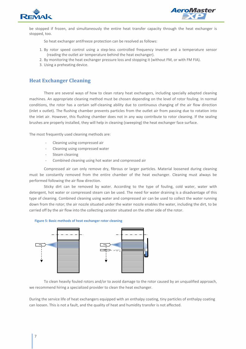
Compressed air can only remove dry, fibrous or larger particles. Material loosened during cleaning
must be constantly removed from the entire chamber of the heat exchanger. Cleaning must always be
performed following the air flow direction.
Sticky dirt can be removed by water. According to the type of fouling, cold water, water with
detergent, hot water or compressed steam can be used. The need for water draining is a disadvantage of this
type of cleaning. Combined cleaning using water and compressed air can be used to collect the water running
down from the rotor; the air nozzle situated under the water nozzle enables the water, including the dirt, to be
carried off by the air flow into the collecting canister situated on the other side of the rotor.
To clean heavily fouled rotors and/or to avoid damage to the rotor caused by an unqualified approach,
we recommend hiring a specialized provider to clean the heat exchanger.
During the service life of heat exchangers equipped with an enthalpy coating, tiny particles of enthalpy coating
can loosen. This is not a fault, and the quality of heat and humidity transfer is not affected.
Figure 5: Basic methods of heat exchanger rotor cleaning
8
Troubleshooting
Rotor Damage
Rough and/or improper heat exchanger handling, exceeding maximum permissible air flow velocities
as well as neglected maintenance can lead to permanent damage to the rotor, i.e. causing the wound layers to
slip down, the reinforcement rotor spokes to break and the entire rotor to collapse. In these cases, expensive
rotor replacement is inevitable.
Rotor Centring
This procedure summarizes the minimum requirements for the heat exchanger rotor centring. The
following conditions must be met:
- The heat exchanger rotor is axially attached to the frame using M16x30 bolts – wrench #24 is needed.
- Access to the rotor centre is enabled through the adjacent sections in the upper duct line.
- If access through the adjacent
sections is not possible, these
sections must be pulled out or
removed from the air-handling
unit assembly.
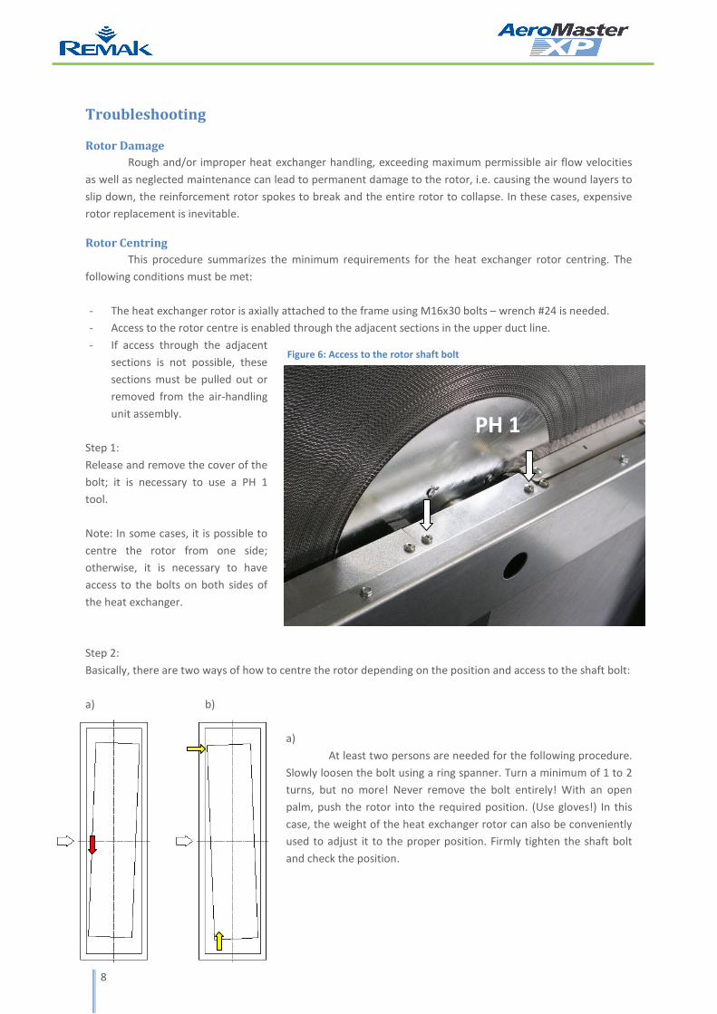
Step 1:
Release and remove the cover of the
bolt; it is necessary to use a PH 1
tool.
Note: In some cases, it is possible to
centre the rotor from one side;
otherwise, it is necessary to have
access to the bolts on both sides of
the heat exchanger.
Step 2:
Basically, there are two ways of how to centre the rotor depending on the position and access to the shaft bolt:
a) b)
a)
At least two persons are needed for the following procedure.
Slowly loosen the bolt using a ring spanner. Turn a minimum of 1 to 2
turns, but no more! Never remove the bolt entirely! With an open
palm, push the rotor into the required position. (Use gloves!) In this
case, the weight of the heat exchanger rotor can also be conveniently
used to adjust it to the proper position. Firmly tighten the shaft bolt
and check the position.
Figure 6: Access to the rotor shaft bolt
PH 1
9
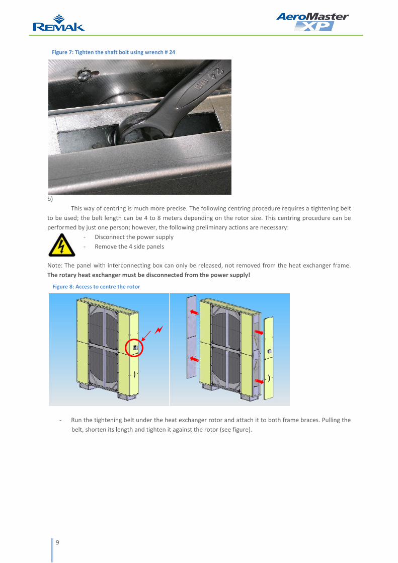
b)
This way of centring is much more precise. The following centring procedure requires a tightening belt
to be used; the belt length can be 4 to 8 meters depending on the rotor size. This centring procedure can be
performed by just one person; however, the following preliminary actions are necessary:
- Disconnect the power supply
- Remove the 4 side panels
Note: The panel with interconnecting box can only be released, not removed from the heat exchanger frame.
The rotary heat exchanger must be disconnected from the power supply!
- Run the tightening belt under the heat exchanger rotor and attach it to both frame braces. Pulling the
belt, shorten its length and tighten it against the rotor (see figure).
Figure 7: Tighten the shaft bolt using wrench # 24
Figure 8: Access to centre the rotor
�

10
- Slowly loosen both shaft bolts using a ring spanner. Turn a minimum of 1 to 2 turns, but no more!
Never remove the bolt entirely!
- With an open palm, push the rotor into the required position. (Use gloves!) The rotor can be raised by
tightening the belt.
- Firmly tighten both shaft bolts and check the position. Then release the tightening belt.
Step 3:
Check all sealing brushes around the rotor circumference as well as in the dividing plane and around
the flushing chamber circumference. If any leaks are found, adjust the sealing brushes by shifting the plastic
bars to the new position. An SQ2 (square) tool is required to loosen the brushes.
Step 4:
Reassemble and reconnect all removed parts.
supporting belt
Figure 9: Supporting the rotor using a tightening belt
11
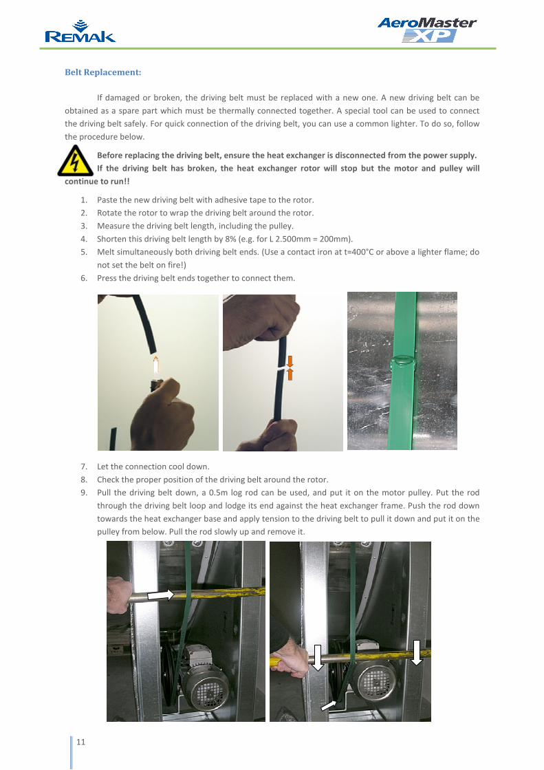
Belt Replacement:
If damaged or broken, the driving belt must be replaced with a new one. A new driving belt can be
obtained as a spare part which must be thermally connected together. A special tool can be used to connect
the driving belt safely. For quick connection of the driving belt, you can use a common lighter. To do so, follow
the procedure below.
Before replacing the driving belt, ensure the heat exchanger is disconnected from the power supply.
If the driving belt has broken, the heat exchanger rotor will stop but the motor and pulley will
continue to run!!
1. Paste the new driving belt with adhesive tape to the rotor.
2. Rotate the rotor to wrap the driving belt around the rotor.
3. Measure the driving belt length, including the pulley.
4. Shorten this driving belt length by 8% (e.g. for L 2.500mm = 200mm).
5. Melt simultaneously both driving belt ends. (Use a contact iron at t=400°C or above a lighter flame; do
not set the belt on fire!)
6. Press the driving belt ends together to connect them.
7. Let the connection cool down.
8. Check the proper position of the driving belt around the rotor.
9. Pull the driving belt down, a 0.5m log rod can be used, and put it on the motor pulley. Put the rod
through the driving belt loop and lodge its end against the heat exchanger frame. Push the rod down
towards the heat exchanger base and apply tension to the driving belt to pull it down and put it on the
pulley from below. Pull the rod slowly up and remove it.
1
2

REMAK a.s.
Zuberská 2601, 756 61 Rožnov pod Radhoštěm,
tel.: +420 571 877 778, fax: +420 571 877 777,
email: [email protected], internet: www.remak.eu
Printing and language mistakes are reserved.
These Installation and Operating Instructions (as a whole or a part) must not be reprinted or copied without prior
written permission from REMAK a. s., Zuberská 2601, Rožnov pod Radhoštěm.
These Installation and Operating Instructions are the sole property of REMAK a. s.
The latest version of this document is available on our website: www.remak.eu.
Changes reserved.
Issued: 11.12.2009


![[1967 Dec. 5] US3355817 Sealing Means for Rotary Drum Heat Exchanger](https://img.pdfslide.net/doc/110x75/5695d4191a28ab9b02a048df/1967-dec-5-us3355817-sealing-means-for-rotary-drum-heat-exchanger.jpg)


![[1981, Nov. 24] US4301860 Rotary Drum Heat Exchanger](https://img.pdfslide.net/doc/110x75/5695d4191a28ab9b02a04831/1981-nov-24-us4301860-rotary-drum-heat-exchanger.jpg)