Embed Size (px)
Citation preview
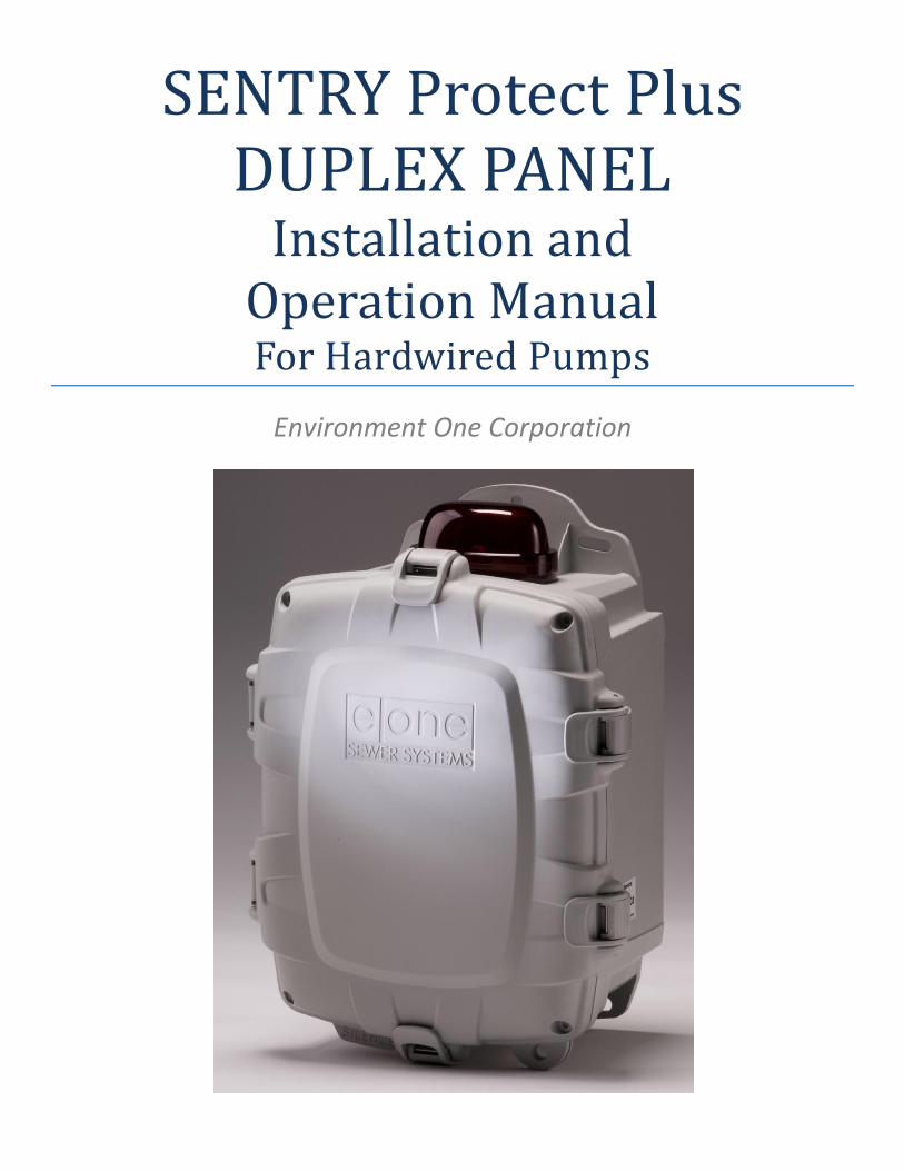
SENTRY Protect Plus DUPLEX PANEL
Installation and Operation Manual For Hardwired Pumps
Environment One Corporation
2 NA0269P03 REV B 12/13/2014
Table of Contents 1 Overview...........................................................................................................................................................................................................................................................................................................................3 2 Sentry Protect Plus Duplex Menu Flowchart .....................................................................................................................................................................................................................................................................4 3 Wiring Instructions ............................................................................................................................................................................................................................................................................................................5
3.1 Alarm Dry Contacts .............................................................................................................................................................................................................................................................................................5 3.2 Switch Over Dry Contacts – to be used with an E/One Remote Sentry (optional) ................................................................................................................................................................................................5
4 Startup ..............................................................................................................................................................................................................................................................................................................................5 5 User Menus and LCD Display .............................................................................................................................................................................................................................................................................................6
5.1 Trouble History Log .............................................................................................................................................................................................................................................................................................6 6 System Initialization ..........................................................................................................................................................................................................................................................................................................7
6.1 Software Revision ...............................................................................................................................................................................................................................................................................................7 6.2 DIP Switch ...........................................................................................................................................................................................................................................................................................................7 6.3 Duplex Pump Modes ...........................................................................................................................................................................................................................................................................................7 6.4 Duplex Alternating Duration ...............................................................................................................................................................................................................................................................................8 6.5 Duplex Alternate .................................................................................................................................................................................................................................................................................................8 6.6 Brownout / Overvoltage Limits ...........................................................................................................................................................................................................................................................................8 6.7 Run Dry (Low Watts) Limits Setting – password protected ..................................................................................................................................................................................................................................8 6.8 Overpressure (High Watts) Limits Setting – password protected .........................................................................................................................................................................................................................8 6.9 User Programmable Options ...............................................................................................................................................................................................................................................................................8
6.9.1 Cold Start ..............................................................................................................................................................................................................................................................................................9 6.9.2 Clear Trouble ........................................................................................................................................................................................................................................................................................9 6.9.3 Alarm Latch Setting ...............................................................................................................................................................................................................................................................................9 6.9.4 Protect Mode Setting ............................................................................................................................................................................................................................................................................9 6.9.5 Buzzer (audible alarm) Timer Setting ..................................................................................................................................................................................................................................................10 6.9.6 Trouble Mode Setting .........................................................................................................................................................................................................................................................................10 6.9.7 Data Push Enable Setting ....................................................................................................................................................................................................................................................................10 6.9.8 Explosion Proof Ready – for use with E/One Explosion Proof grinder pumps only ...............................................................................................................................................................................10 6.9.9 Restore Factory Defaults .....................................................................................................................................................................................................................................................................10 6.9.10 Calibrate – password protected ..........................................................................................................................................................................................................................................................11 6.9.11 Reset Calibration – password protected..............................................................................................................................................................................................................................................11 6.9.12 Custom Settings ..................................................................................................................................................................................................................................................................................11
6.10 Run Limit Setting ...............................................................................................................................................................................................................................................................................................12 6.11 Alarm Delay Setting ..........................................................................................................................................................................................................................................................................................12 6.12 Power Delay Setting ..........................................................................................................................................................................................................................................................................................13
7 Normal Operation ...........................................................................................................................................................................................................................................................................................................13 7.1 Manual Run Operation ......................................................................................................................................................................................................................................................................................14 7.2 High Level Alarm Operation ..............................................................................................................................................................................................................................................................................14 7.3 Trouble Alarm Indication ..................................................................................................................................................................................................................................................................................14 7.4 Audible Alarm Manual Silence ..........................................................................................................................................................................................................................................................................16 7.5 Pump Performance ...........................................................................................................................................................................................................................................................................................16
7.5.1 Pump 1 / 2 ..........................................................................................................................................................................................................................................................................................16 7.5.2 Normal Hour Meter ............................................................................................................................................................................................................................................................................16 7.5.3 Normal Cycle Counter .........................................................................................................................................................................................................................................................................16 7.5.4 Manual Run Hour Meter .....................................................................................................................................................................................................................................................................16 7.5.5 Manual Run Cycle Counter ..................................................................................................................................................................................................................................................................16 7.5.6 Last Runtime .......................................................................................................................................................................................................................................................................................16 7.5.7 Minimum Runtime ..............................................................................................................................................................................................................................................................................16 7.5.8 Maximum Runtime .............................................................................................................................................................................................................................................................................16 7.5.9 Average Runtime ................................................................................................................................................................................................................................................................................16 7.5.10 Minimum Amps ..................................................................................................................................................................................................................................................................................17 7.5.11 Maximum Amps ..................................................................................................................................................................................................................................................................................17 7.5.12 Average Amps .....................................................................................................................................................................................................................................................................................17 7.5.13 Minimum Volts ...................................................................................................................................................................................................................................................................................17 7.5.14 Maximum Volts...................................................................................................................................................................................................................................................................................17 7.5.15 Average Volts ......................................................................................................................................................................................................................................................................................17 7.5.16 Minimum Watts ..................................................................................................................................................................................................................................................................................17 7.5.17 Maximum Watts .................................................................................................................................................................................................................................................................................17 7.5.18 Average Watts ....................................................................................................................................................................................................................................................................................17 7.5.19 Leak Detected (read-only leak indication field, E/One explosion proof pumps only) ...........................................................................................................................................................................17 7.5.20 Clear Counters (cycles, hour meters, averages) ...................................................................................................................................................................................................................................17 7.5.21 Clear Minimums and Maximums.........................................................................................................................................................................................................................................................17 7.5.22 Clock Error ..........................................................................................................................................................................................................................................................................................18
8 Trouble Operation...........................................................................................................................................................................................................................................................................................................18 8.1 Excessive Runtime Operation ............................................................................................................................................................................................................................................................................18 8.2 Brownout Operation .........................................................................................................................................................................................................................................................................................18 8.3 Overvoltage Operation .....................................................................................................................................................................................................................................................................................18 8.4 Run Dry Operation ............................................................................................................................................................................................................................................................................................18 8.5 Overpressure Operation ...................................................................................................................................................................................................................................................................................19 8.6 Alarm Circuit Protection Active .........................................................................................................................................................................................................................................................................19 8.7 Faulty Watt-meter Operation............................................................................................................................................................................................................................................................................19 8.8 Comm Lost Indication .......................................................................................................................................................................................................................................................................................19 8.9 Leak Detect Operation (E/One explosion proof pumps only) .............................................................................................................................................................................................................................20
9 Diagnostics ......................................................................................................................................................................................................................................................................................................................20 9.1 LED Test ............................................................................................................................................................................................................................................................................................................20 9.2 Button Test .......................................................................................................................................................................................................................................................................................................20 9.3 Relay Test .........................................................................................................................................................................................................................................................................................................20
10 Communication...............................................................................................................................................................................................................................................................................................................20 10.1 Serial Interface ..................................................................................................................................................................................................................................................................................................21 10.2 Sentry Advisor Option .......................................................................................................................................................................................................................................................................................21
11 Trouble Shooting .............................................................................................................................................................................................................................................................................................................22 11.1 Troubleshooting Chart ......................................................................................................................................................................................................................................................................................22
12 Appendix .........................................................................................................................................................................................................................................................................................................................24 12.1 System Parameters Memory Map .....................................................................................................................................................................................................................................................................24 12.2 LCD Messages ...................................................................................................................................................................................................................................................................................................25 12.3 Wiring Diagrams ...............................................................................................................................................................................................................................................................................................26
12.3.1 Typical Pump Wiring Diagram – 240V 2-Leg (Extreme Hardwired) ......................................................................................................................................................................................................26 12.3.2 Typical Pump Wiring Diagram – 240V 2-Leg (Extreme Wireless / Explosion Proof) ..............................................................................................................................................................................27 12.3.3 Typical Pump Wiring Diagram – 240V 1-Leg (Extreme Hardwired) ......................................................................................................................................................................................................28 12.3.4 Typical Pump Wiring Diagram – 240V 1-Leg (Extreme Wireless / Explosion Proof) ..............................................................................................................................................................................29 12.3.5 240V, 2-leg panel wiring, optional Main Service Disconnect and GFCI outlet (for US installations) ......................................................................................................................................................30 12.3.6 240V, 1-leg basic panel wiring (for non-US installations) .....................................................................................................................................................................................................................31
3 NA0269P03 REV B 12/13/2014
1 Overview This manual provides information on the operation and use of Environment One Protect Plus Duplex Panels. If unsure of the configuration of your panel, contact E/One factory for assistance. The Sentry Protect Plus Duplex panel is an Environment One full-featured Alarm/Monitor panel. The Sentry Protect Plus Duplex panel monitors for the following operating conditions:
Pump Run Dry Condition – Pump running out of water
Pump Overpressure Condition – Pump operating at abnormally high wattage level
Brownout Condition – Mains voltage under 12% of nameplate rating
Overvoltage Condition – Mains voltage above 12% of nameplate rating
High Liquid Level
Real-time, High, and Low Voltage to the Pump
Real-time, High, and Low Wattage drawn by the Pump
Extended Pump Runtime (field programmable limit)
The Sentry Protect Plus Duplex Panel displays pump status, operating parameters, and user options by means of the following indicators:
LCD Display to show Pump & Panel operating conditions
Four Status Indicators: o Ready (Green LED) o Pump Running (Green LED) o Trouble (Amber LED) o High Level Alarm (Red LED)
Eight Selectable Modes to view or change panel operation
Menu Navigation Buttons – Enter, Scroll, Mode, ↑ ‘A’ and ↓ ‘B’
In addition, the following pump operating parameters can be viewed from the Sentry Protect Plus Duplex Panel:
Real-time pump Voltage, Amperage, and Wattage (power)
Cycles & Hours (resettable)
Minimum, Maximum, Average, and Last Run Cycle in Minutes (resettable)
Minimum, Maximum and Average Voltage, Amperage, and Wattage (resettable)
Latched fault conditions
The following features are field programmable:
Excessive Run Time
Alarm On Delay
Power On Delay
The following are the hardware features:
IP65 / NEMA 4X Rated Enclosure
Enclosure made from Thermoplastic Polyester
Separate Alarm and Pump Circuit Breakers
Audible & Visual Alarm indicators (Silence for Audible Alarm)
Manual Pump Run Button
Remote Sentry Alarm Dry Contacts – Normally Open, rated for 24VDC, 2A maximum (Can operate with or without power. Intended for use with Environment One Remote Sentry, sold separately)
Alarm Dry Contacts – Normally Open (Requires alarm board to have power)
4 NA0269P03 REV B 12/13/2014
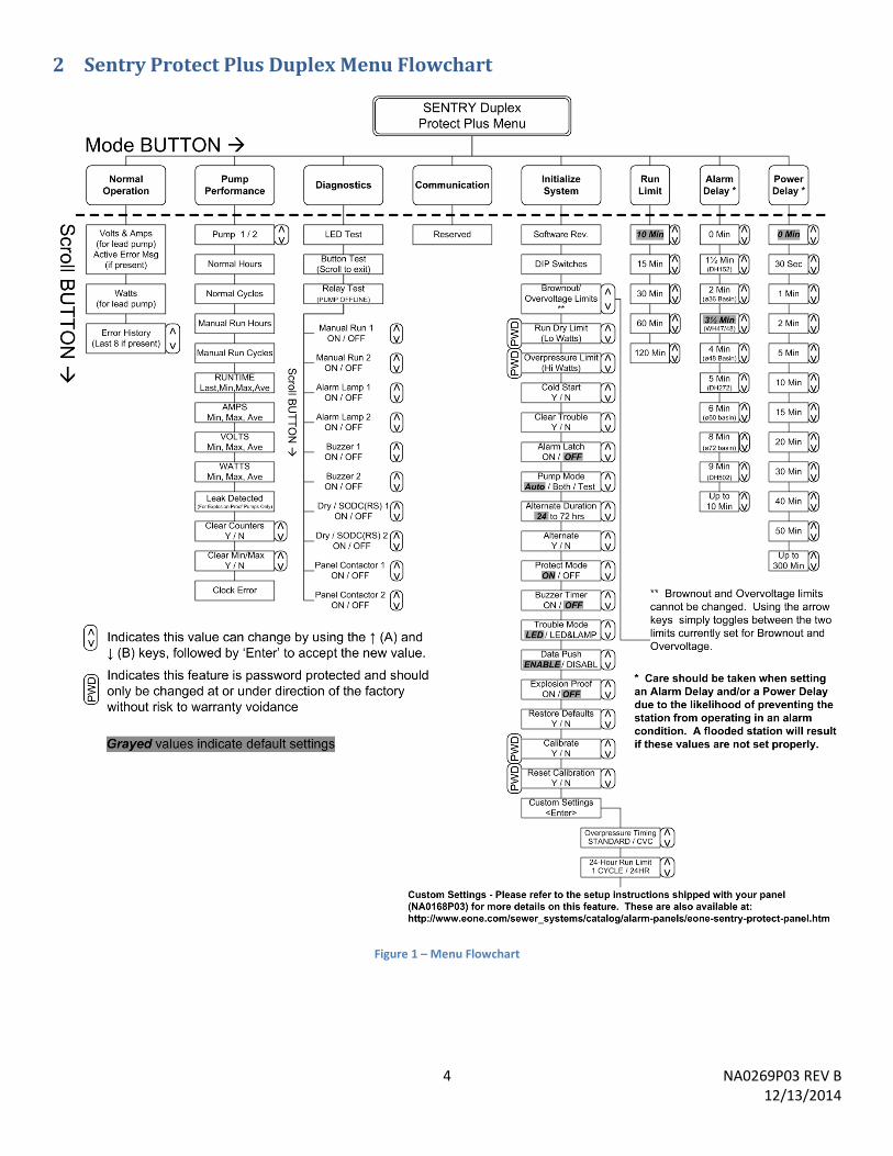
2 Sentry Protect Plus Duplex Menu Flowchart
Figure 1 – Menu Flowchart
5 NA0269P03 REV B 12/13/2014
3 Wiring Instructions
WARNING – the E/One Alarm and Control panel is a high voltage system that controls power to an electric motor. Care should be taken whenever performing service on the panel to avoid the risk of electrical shock and/or damage to property. Because power may be supplied by multiple sources, circuit breakers alone may not be sufficient to provide adequate protection.
Due to the many different optional features, the Sentry Protect Plus Duplex panel wiring can change from model to model. All wiring shall be done in accordance with the wiring decal on the inside cover of the panel enclosure. Several examples of typical wiring can be found in the Appendix of this manual.
3.1 Alarm Dry Contacts
Warning! These dry contacts are capable of a maximum of 2A. Connections that exceed this maximum value can cause permanent damage to the printed circuit board within the panel.
The Sentry Protect Plus Duplex panel is equipped with one set of dry contacts that coincide with the following alarm indications:
High Water Level
Run Dry (after third failed re-try) Overpressure (after third failed re-try)
These dry contacts will close upon detection of any of the above listed events and remain closed until the condition is removed or cleared. If the Alarm Latch option is set to ‘ON’, these dry contacts will also be latched until the condition is cleared. Refer to the Alarm Latch section of this manual for more information on this feature.
3.2 Switch Over Dry Contacts – to be used with an E/One Remote Sentry (optional)
Warning! These dry contacts are designed to be used in conjunction with an E/One Remote Sentry device, and are capable of a maximum of +24VDC and 2A. Connections that exceed these maximum values can cause permanent damage to the printed circuit board within the panel.
The Sentry Protect Plus Duplex panel is equipped with one set of switch over dry contacts. If power is applied to the panel these contacts respond just as the Alarm Dry Contacts described above. When connected to an E/One Remote Sentry, that device will respond with an audible and visual alarm in conjunction with above indicated alarm conditions. If power to the panel is lost these contacts are ‘switched over’ to connect directly to the alarm switch in the pump. In this configuration, the Remote Sentry device will respond with an audible and visual alarm any time the alarm switch closes, allowing the use of water even during a power outage. When power is restored to the panel, these dry contacts will switch back to their normal position. If the Alarm Latch option is set to ‘ON’, these dry contacts will also be latched until the condition is cleared. Refer to the Alarm Latch section of this manual for more information on this feature.
4 Startup The Sentry Protect Plus Duplex Panel should arrive from the factory ready to operate. The panel is properly installed and started by following the steps below.
1. Mount and wire the panel per the instructions on the enclosure door. 2. ‘Cold Start’ the panel – refer to Cold Start section of this manual for more information. 3. If other than factory default settings are required, set all limits, delays, and operating modes. Factory defaults
settings can also be restored via the user menu. (Refer to the User Programmable Options section of this manual for more on this feature).
6 NA0269P03 REV B 12/13/2014
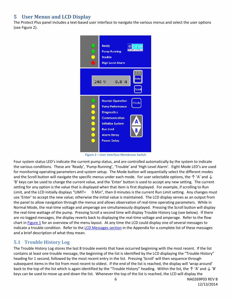
5 User Menus and LCD Display The Protect Plus panel includes a text-based user interface to navigate the various menus and select the user options (see Figure 2).
Figure 2 – User Interface Membrane Switch
Four system status LED’s indicate the current pump status, and are controlled automatically by the system to indicate the various conditions. These are ‘Ready’, ‘Pump Running’, ‘Trouble’ and ‘High Level Alarm’. Eight Mode LED’s are used for monitoring operating parameters and system setup. The Mode button will sequentially select the different modes and the Scroll button will navigate the specific menus under each mode. For user selectable options, the ↑ ‘A’ and ↓ ‘B’ keys can be used to change the current value, and the ‘Enter’ button is used to accept any new setting. The current setting for any option is the value that is displayed when that item is first displayed. For example, if scrolling to Run Limit, and the LCD initially displays “LIMIT= 0 Min”, then 0 minutes is the current Run Limit setting. Any changes must use ‘Enter’ to accept the new value; otherwise the initial value is maintained. The LCD display serves as an output from the panel to allow navigation through the menus and allows observation of real-time operating parameters. While in Normal Mode, the real-time voltage and amperage are simultaneously displayed. Pressing the Scroll button will display the real-time wattage of the pump. Pressing Scroll a second time will display Trouble History Log (see below). If there are no logged messages, the display reverts back to displaying the real-time voltage and amperage. Refer to the flow chart in Figure 1 for an overview of the menu layout. At any time the LCD could display one of several messages to indicate a trouble condition. Refer to the LCD Messages section in the Appendix for a complete list of these messages and a brief description of what they mean.
5.1 Trouble History Log The Trouble History Log stores the last 8 trouble events that have occurred beginning with the most recent. If the list contains at least one trouble message, the beginning of the list is identified by the LCD displaying the “Trouble History” heading for 1 second, followed by the most recent entry in the list. Pressing ‘Scroll’ will then sequence through subsequent items in the list from most recent to oldest. If the end of the list is reached, the display will ‘wrap around’ back to the top of the list which is again identified by the “Trouble History” heading. Within the list, the ↑ ‘A’ and ↓ ‘B’ keys can be used to move up and down the list. Whenever the top of the list is reached, the LCD will display the
7 NA0269P03 REV B 12/13/2014
“Trouble History” heading. While displaying any trouble message in the list, pressing ‘Enter’ will display the Runtime of the pump that was active at the time the trouble event occurred. This is intended to provide a sort of timestamp of when the event occurred. This information can also indicate how frequently a trouble event is occurring when comparing to other items in the list. Pressing ‘Enter a second time will display the Cycles of the pump that was active at the time of the event. Like the Runtime, this is intended to provide information on when and how often a trouble event is occurring. Every item in the list will contain these additional pieces of information to help provide an overview of the chain of events leading up to a particular trouble condition, to help with troubleshooting a problem.
6 System Initialization A number of system settings, some of which will be unique to the installation, can be set on-site. Most of these settings can be found within the Initialize System mode; however Run Limit, Alarm Delay, and Power Delay each have their own mode for configuration. The following sections describe each of the items contained within the Initialize System mode.
6.1 Software Revision This read only field displays the part number and revision of the software currently loaded into the panel. This information may be required when speaking with E/One service personnel.
6.2 DIP Switch This read only field displays the setting of the four position miniature switch (DIP switch) located on the printed circuit board within the panel (labeled S1). These switches configure the Sentry Protect Plus Duplex for the operating environment in which the panel is being installed. From left to right, the first three positions configure the voltage setting as shown in the table below. The right most position is used to configure the panel for use with a wireless grinder pump (refer to the Wireless and Explosion Proof Pump Operation section of this manual for more information). In the following voltage selection table, “U” represents a switch in the Up (ON) position and ‘D’ represents a switch in the Down (OFF) position. The DIP switch must be programmed with power to the alarm board off (Alarm Breaker off). While this setting is typically performed at the factory, it is essential that the DIP switch is properly set for the AC Mains voltage applied for the panel to operate properly.
Input Voltage 1 2 3 4 240 VAC, 60 Hz UUUX 240 VAC, 50 Hz UUDX 230 VAC, 50 Hz UDUX 120 VAC, 60 Hz UDDX 200 VAC, 50 Hz DUUX RESERVED DUDX, DDUX Factory Use Only DDDX
Warning! DIP switch position 4 is to be set to ‘D’ for hardwired pumps (factory default).
6.3 Duplex Pump Modes The Duplex Mode is a user selectable feature that can be set from the ‘Duplex Mode’ menu within the Initialize System mode. This feature is specific to duplex systems only and allows selecting between two operational modes and one test mode. The default setting for this option is AUTO. From the Duplex Mode menu, use the ↑ ‘A’ and ↓ ‘B’ keys to change the selection. Once the desired mode is selected, press ‘Enter’ to accept the new value (pressing ‘Mode’ or ‘Scroll’ will exit without saving the change); the LCD will display ‘Writing…’. The first and default setting is AUTO which configures the duplex system for a time-based alternating sequence. In this mode only one pump, the lead pump, is powered at any given time, and the other pump, the lag pump, is disabled. After a set time (as determined by the Duplex Alternating Duration setting), the lead/lag relationship switches pumps. The lead pump is allowed to run unless a condition exists that would prevent that pump from operating (Brownout, Run Dry, etc.). In these cases, the lead pump would be deactivated until the condition is no longer present. Refer to the Trouble Operation section of this manual for more information on these scenarios. If a high level occurs at any time, the
8 NA0269P03 REV B 12/13/2014
lag pump would become active and allowed to operate. Refer to the High Level Alarm section of this manual for more on this condition. The second duplex operating mode is BOTH which configures the system to activate both pumps simultaneously to a ready state. In this mode each pump operates independently. Due to the variation in each pumps ON/OFF level, one pump will most likely be activated first, and the second pump will only be activated if the in-flow of the station is more than the first pump can handle. This will likely result in mismatched wear between the two pumps and is not recommended to achieve the full benefit of a duplex station. The third duplex mode is TEST and mimics the time-based alternation of the AUTO mode. This mode is intended to be used only temporarily during station startup to verify that the system alternates between the two pumps properly. The difference the TEST mode provides over AUTO is that the alternating duration is forced to 1 minute. The 1-minute alternation will last for a total of 5 minutes, alternating between the two pumps as described in the AUTO section. During these 5 minutes “DUPLEX TEST MODE” will be displayed on the LCD screen, and the Alarm Lamp will flash to indicate that the TEST mode is active. After the 5th alternation, the system will default back to the AUTO mode. While this mode will revert back to AUTO on its own, it is advised that the intended duplex operating mode is selected prior to leaving the station.
6.4 Duplex Alternating Duration The Duplex Alternating Duration is a user selectable feature that can be set using the ‘Duplex Alternating Duration’ menu within the Initialize System mode. This field allows selecting the time-based alternating duration for the AUTO duplex operating mode. The default setting for this option is 24 hours. From the Duplex Alternating Duration menu, use the ↑ ‘A’ and ↓ ‘B’ keys to change the selection from 24 to 72 hours in 12-hour increments. Once the desired duration is selected, press ‘Enter’ to accept the new value (pressing ‘Mode’ or ‘Scroll’ will exit without saving the change); the LCD will display ‘Writing…’.
6.5 Duplex Alternate Duplex Alternate is a user feature that can be activated by using the ‘Alternate’ menu within the Initialize System mode. This feature allows manually alternating the lead / lag relationship from one pump to the other. From the Alternate menu, use the ↑ ‘A’ and ↓ ‘B’ keys to choose between ‘N’ (no) and ‘Y’ (yes). With ‘Y‘ selected, pressing ‘Enter’ will immediately alternate the lead / lag relationship of the pumps (pressing ‘Mode’ or ‘Scroll’ will exit without clearing). Pressing ‘Enter’ will continue to alternate the pumps as long as ‘Y’ is selected.
6.6 Brownout / Overvoltage Limits This read-only field displays the limits that are currently set for both Brownout and Overvoltage. When in this menu, pressing the ↑ ‘A’ and ↓ ‘B’ keys will toggle between these two limits. These values cannot be changed.
6.7 Run Dry (Low Watts) Limits Setting – password protected This field displays the limit that is currently set for the Run Dry / Low Watts protection feature. Though it is possible to change this setting, it is not advised unless directed by E/One service personnel, as changing this limit will affect how the protection feature performs. Doing so without proper guidance may void the product warranty and can cause damage to the system.
6.8 Overpressure (High Watts) Limits Setting – password protected This field displays the limit that is currently set for the Overpressure / High Watts protection feature. Though it is possible to change this setting, it is not advised unless directed by E/One service personnel, as changing this limit will affect how the protection feature performs. Doing so without proper guidance may void the product warranty and can cause damage to the system.
6.9 User Programmable Options The following items found within the Initialize System mode can be used for system setup. In a duplex system all of these parameters are shared between the two pumps and cannot be set independently for each pump. Clearing of these values is also universal and affects both pumps simultaneously.
9 NA0269P03 REV B 12/13/2014
6.9.1 Cold Start The Cold Start option is found within the Initialize System mode. Cold Starting the panel erases all stored operating parameters listed within the Pump Performance mode as well as Trouble History Log messages, and should be done when the panel is first installed. From the Cold Start menu, use the ↑ ‘A’ and ↓ ‘B’ keys to alternate the selection between ‘N’ (no) and ‘Y’ (yes). Once ‘Y‘ is selected, press ‘Enter’ to accept; the panel asks ‘Are You Sure?’. Pressing ‘Enter’ at this point will initiate a Cold Start of the panel (pressing ‘Mode’ or ‘Scroll’ will exit without Cold Starting). The LCD will display ‘Cold Starting…’, after which the panel will restart. All previously stored operating parameters will be cleared.
6.9.2 Clear Trouble Clear Trouble is a user selectable feature that can be applied by using the ‘Clear Trouble?’ menu within the Initialize System mode. This feature allows the user to clear all fault conditions that are currently stored in the Trouble History Log. Make sure to record all trouble message information for future reference before clearing the trouble history. From the Clear Trouble menu, use the ↑ ‘A’ and ↓ ‘B’ keys to alternate the selection between ‘N’ (no) and ‘Y’ (yes). Once ‘Y‘ is selected, press ‘Enter’ to accept (pressing ‘Mode’ or ‘Scroll’ will exit without clearing); the LCD will display ‘Clearing…’. Clear Trouble has no effect on any output that is active due to a present trouble condition.
6.9.3 Alarm Latch Setting The Alarm Latch is a user selectable feature that can be set using the ‘Alarm Latch’ menu within the Initialize System mode. A latched Alarm means that, despite the alarm condition no longer being present, the indications associated with that alarm remain active indefinitely, until cleared. The following conditions are considered alarms and can be latched:
High Water Level
Run Dry (after third failed re-try) Overpressure (after third failed re-try)
The factory default setting for this option is OFF. From the Alarm Latch menu, use the ↑ ‘A’ and ↓ ‘B’ keys to change the selection from ‘N’ (no) to ‘Y’ (yes). Once ‘Y‘ is selected, press ‘Enter’ to accept the new value (pressing ‘Mode’ or ‘Scroll’ will exit without saving the change); the LCD will display ‘Writing…’. If set to ‘ON’, this feature will cause the panel to latch all Alarm outputs. This includes the Alarm Lamp, High Level Alarm LED, Dry & Remote Sentry Contacts, and the audible alarm (Run Dry does not result in an audible alarm). The audible alarm will silence itself after a non-configurable set time of 10 minutes or can be silenced manually using the silence switch. All other outputs (contacts, indications, etc.) remain latched indefinitely until cleared. The condition can be cleared by using the ‘Clear Trouble’ option under the Initialize System menu or if the Alarm Latch Option is turned off and a subsequent Alarm event completes.
6.9.4 Protect Mode Setting
Warning! Setting this option to ‘OFF’ will revert the panel to a basic, non-protection mode, and should only be done as a last resort to keep the station functioning in a basic state for a short time until the station can be repaired.
The Protect option is a user selectable feature that can be cleared using the ‘Protect’ menu within the Initialize System mode. The factory default setting for this option is ON. From the Protect menu, use the ↑ ‘A’ and ↓ ‘B’ keys to alternate the selection between ‘ON’ and ‘OFF’. Once the desired setting is selected, press ‘Enter’ to accept; the panel asks ‘Are You Sure?’. Pressing ‘Enter’ will accept the new value (pressing ‘Mode’ or ‘Scroll’ will exit without saving the change); the LCD will display ‘Writing…’. In the ‘ON’ position, the alarm panel will actively monitor Voltage, Amperage and Wattage and react to the following adverse operating conditions: Brownout, Overvoltage, Run Dry and Overpressure. This includes disabling the pump if any of the parameters are outside of the set limits (refer to the Trouble Operation section of this manual). If set to ‘OFF’, the panel will continue to monitor Voltage, Amperage & Wattage, however it will take no action if any of these parameters fall outside of their set limits. This option can be used in cases where the protect features are not working properly and are preventing the pump from operating despite no out of limit conditions being present. Setting this option to ‘OFF’ will revert the panel to a non-protection mode until the panel can be repaired.
10 NA0269P03 REV B 12/13/2014
6.9.5 Buzzer (audible alarm) Timer Setting The Buzzer Timer allows the audible alarm to automatically silence after a non-configurable time of 10 minutes; all other alarm indications will persist as long as the alarm is active. This option is a user selectable feature that can be set using the ‘Buzzer Timer’ menu within the Initialize System mode. The factory default setting for this option is OFF. From the Buzzer Timer menu, use the ↑ ‘A’ and ↓ ‘B’ keys to alternate the selection between ‘ON’ and ‘OFF’. Once the desired setting is selected, press ‘Enter’ to accept the new value (pressing ‘Mode’ or ‘Scroll’ will exit without saving the change); the LCD will display ‘Writing…’. If set to ‘ON’, this feature will silence the audible alarm after a non-configurable set time of 10 minutes. If the alarm condition terminates or the manual silence is pressed before the buzzer timer has expired, the audible alarm will silence without having reached the end of the 10 minutes. This timer resets to 10 minutes after an alarm has cleared.
6.9.6 Trouble Mode Setting The Trouble Mode is a user selectable feature that can be set using the ‘Trouble’ menu within the Initialize System mode. The factory default setting for this option is LED ONLY. In this position, any trouble alarm will be indicated only by the Trouble LED. From the Trouble Mode menu, use the ↑ ‘A’ and ↓ ‘B’ keys to change the selection from ‘LED ONLY’ to ‘LED/LAMP’. Once the desired setting is selected, press ‘Enter’ to accept the new value (pressing ‘Mode’ or ‘Scroll’ will exit without saving the change); the LCD will display ‘Writing…’. In the LED/LAMP position, any trouble alarm will be indicated by the Trouble LED as well as a flashing alarm lamp. Trouble alarms are triggered by the following:
Brownout
Overvoltage
Excessive Run Time Limit
Run Dry (Trouble for first 3 re-tries, then Alarm)
Overpressure (Trouble for first 3 re-tries, then Alarm) Faulty Watt-meter
For Run Dry and Overpressure, only the first three occurrences are considered trouble events, after which they become alarms. Refer to their respective sections of this manual for how these conditions affect the Trouble LED and Alarm Lamp.
6.9.7 Data Push Enable Setting The Data Push is a feature used only with panels equipped with the Advanced Data option of the E/One Sentry Advisor Remote Monitoring System, or an equivalent SCADA system capable of interpreting the serial data transmitted from the panel. This feature allows all registers stored locally within the panel to be transmitted out over the Sentry Advisor System in response to a pump run cycle. These registers store all information regarding pump performance, system status, as well as user settings to allow viewing these parameters remotely. Refer to the System Parameters Memory Map section of this manual for more detail on the registers that are transmitted with the Data Push feature. The factory default setting for this option is ENABLE. From the Data Push menu, use the ↑ ‘A’ and ↓ ‘B’ keys to alternate the selection between ‘ENABLE’ and ‘DISABL’. Once the desired setting is selected, press ‘Enter’ to accept the new value (pressing ‘Mode’ or ‘Scroll’ will exit without saving the change); the LCD will display ‘Writing…’. If set to ‘ENABLE’, this feature will result in all registers being transmitted as a single data packet approximately 10 seconds after the start of each pump run cycle.
6.9.8 Explosion Proof Ready – for use with E/One Explosion Proof grinder pumps only This option does not apply to hardwired pumps and should be left in the default (OFF) setting. Contact E/One for more information.
6.9.9 Restore Factory Defaults The Restore Defaults option is a user selectable feature that can be applied by using the ‘Restore?’ menu within the Initialize System mode. From the Restore menu, use the ↑ ‘A’ and ↓ ‘B’ keys to alternate the selection between ‘N’ and ‘Y’. Once ‘Y’ is selected, press ‘Enter’ to restore the factory default settings (pressing ‘Mode’ or ‘Scroll’ will exit without restoring); the LCD will display ‘Restoring…’. Restoring the factory default values returns the following fields to their factory preset conditions [factory default]: Pump Mode [BOTH], Alternating Duration[24 HRS], Run Dry Limit [based
11 NA0269P03 REV B 12/13/2014
on DIP Switch setting], Overpressure Limit [based on DIP Switch setting], Alarm Latch [OFF], Protect Mode [ON], Audible Alarm Timer [OFF], Trouble Mode [LED ONLY], Data Push Enable [ENABLE], Explosion Proof [OFF], Run Limit [10 MINUTES], Alarm Delay [3.5 MIN], and Power Delay [NONE].
6.9.10 Calibrate – password protected Calibrate is a factory only feature that is located in the ‘Calibrate?’ menu within the Initialize System mode. Calibration is performed at the factory and is necessary to provide the system with baseline Voltage, Amperage, and Wattage settings. The process uses a special fixture capable of applying highly accurate values to the system. Once applied, a calibration measurement is taken to establish reference values for these operating parameters. Performing a calibration without the proper equipment will cause the system to malfunction and is not to be performed by anyone outside of factory personnel.
6.9.11 Reset Calibration – password protected The Reset Calibration option is a user selectable feature that can be applied by using the ‘Reset Cal?’ menu within the Initialize System mode. Reset Calibration should only be performed if it is known that the factory calibration has been compromised. Refer to the troubleshooting guide at the back of this manual for more information on making this determination. Performing a reset cal will reset the calibration settings to default values, which may not be precisely correct for a specific panel, but should be adequate to allow the system to temporarily function until the panel can be repaired.
CAUTION: This should only be done as a last resort if the panel is non-operational, and until the panel can be repaired. This will allow the panel to perform its protect function, but the set limits may not be highly accurate.
6.9.12 Custom Settings The Custom Settings menu contains features that were not standard on the original release of the Protect Panel, but were either requested by a specific job or suggested generally as being a useful feature to add. This allows the addition of newer options that may arise as the product matures with minimal changes to other product documentation. This sub-menu is available via the ‘Custom Settings’ menu within the Initialize System mode. Pressing ‘Enter’ from the ‘Custom Settings’ menu will open a new list of additional features that may be added to from time to time by Environment One. This menu can be navigated using the ‘Enter’, ‘Scroll’, ↑ ‘A’ and ↓ ‘B’ keys just as any other menu. Pressing ‘Mode’ will return to the Initialize System mode. While this manual is intended to be updated periodically to reflect all such additions to the Custom Settings menu, it is possible that items have been added that are not reflected herein. Check the website for the latest version of this manual, or the installation instructions that were shipped with the panel (NA0168P02, also available on the website), for the most up to date information.
6.9.12.1 OP (Overpressure) Timing Mode
This option provides an alternate method for retrying to start the motor after an Overpressure Lockout. Refer to the paragraph on Overpressure in the Trouble Operation section of this manual for more on this feature.
The OP Timing Mode is a user selectable feature that can be set using the ‘OP Mode: ’ menu within the Custom Settings section of the Initialize System mode. The factory default setting for this option is Standard. From the OP Mode menu, use the ↑ ‘A’ and ↓ ‘B’ keys to alternate the selection between ‘Standard’ and ‘CVC’. Once the desired setting is selected, press ‘Enter’ to accept the new value (pressing ‘Mode’ or ‘Scroll’ will exit without saving the change); the LCD will display ‘Writing…’. If set to ‘Standard’, the lockout / re-try timing for an Overpressure event consists of 3, 20-minute lockout cycles with a re-try of the pump after each lockout. ‘CVC’ is a custom setting where the lockout / re-try timing consists of 4, 30-minute, followed by 6, 60 minute lockout cycles with a re-try of the pump after each lockout. In either case, after the final failed attempt, the pump is disabled indefinitely until power is reset.
12 NA0269P03 REV B 12/13/2014
6.9.12.2 24-hour Run Limit
This setting works in conjunction with the Run Limit Mode and provides an alternate method for determining a Run Time Alarm based on the duration set for that feature. Refer to the Run Limit section of this manual for more on this feature.
The 24-hour Run Limit is a user selectable feature that can be set using the ’Run Limit: ’ menu within the Custom Settings section of the Initialize System mode (separate from the Run Limit Mode which is explained in the following section). The factory default setting for this option is 1 Cyc (1 pump run cycle). From the Run Limit menu, use the ↑ ‘A’ and ↓ ‘B’ keys to change the selection from ‘1 Cyc’ to ‘24Hr’. Once the desired setting is selected, press ‘Enter’ to accept the new value (pressing ‘Mode’ or ‘Scroll’ will exit without saving the change); the LCD will display ‘Writing…’. If set to ‘1Cyc’, this feature will issue a trouble alarm for an excessive runtime based on the duration of a single pump cycle. If set to ‘24Hr’, the trouble alarm for a Run Time Alarm will be based on the accumulated runtime of all pump cycles over a 24-hour period, beginning with when the option is first set.
6.10 Run Limit Setting The Run Limit option is a user selectable feature that can be set from the Run Limit mode. The factory default setting for this feature is 10 minutes. This feature will cause a trouble alarm to be initiated if an individual pump run cycle exceeds the set value (assumes 24-hour Run Limit is set to 1 cyc). For an alternate way to configure this feature, refer to the 24-hour Run Limit section of this manual. This feature only indicates a trouble alarm; it does not disable the pump. Using the ‘Enter’, ‘Scroll’, ↑ ‘A’ and ↓ ‘B’ keys, the Run Limit can be set to any value between 10 and 120 minutes. For convenience, the following presets have been programmed:
10 minutes
15 minutes
30 minutes
60 minutes
120 minutes
‘Scroll’ will step through this list of preset values, while ↑ ‘A’ and ↓ ‘B’ will increase or decrease the current value in 1 minute increments. Once the desired value is reached, pressing ‘Enter’ will commit the value to memory (pressing ‘Mode’ or ‘Scroll’ will exit without saving the change).
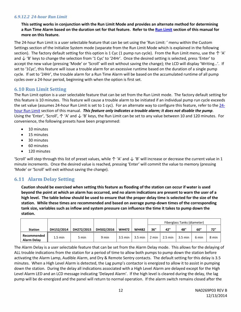
6.11 Alarm Delay Setting
Caution should be exercised when setting this feature as flooding of the station can occur if water is used beyond the point at which an alarm has occurred, and no alarm indications are present to warn the user of a high level. The table below should be used to ensure that the proper delay time is selected for the size of the station. While these times are recommended and based on average pump-down times of the corresponding tank size, variables such as inflow and system pressure can influence the time it takes to pump down the station.
Station DH152/2014 DH272/2015 DH502/2016 WH472 WH482
Fiberglass Tanks (diameter)
36" 42" 48" 60" 72"
Recommended Alarm Delay
1.5 min 5 min 9 min 3.5 min 3.5 min 2 min 2.5 min 3.5 min 6 min 8 min
The Alarm Delay is a user selectable feature that can be set from the Alarm Delay mode. This allows for the delaying of ALL trouble indications from the station for a period of time to allow both pumps to pump down the station before activating the Alarm Lamp, Audible Alarm, and Dry & Remote Sentry contacts. The default setting for this delay is 3.5 minutes. When a High Level Alarm is detected, the Lag pump’s contactor is energized to allow it to assist in pumping down the station. During the delay all indications associated with a High Level Alarm are delayed except for the High Level Alarm LED and an LCD message indicating ‘Delayed Alarm’. If the high level is cleared during the delay, the lag pump will be de-energized and the panel will return to normal operation. If the alarm switch remains closed after the
13 NA0269P03 REV B 12/13/2014
delay time has expired the station will activate all high level alarm indications. Refer to the High Level Alarm section of this document for more information.
Using the ‘Enter’, ‘Scroll’, ↑ (A), and ↓ (B) keys, the Alarm Delay can be set to any value between 0 and 10 minutes. ‘Scroll’ will step through the list of preset values, while ↑ ‘A’ and ↓ ‘B’ will increase or decrease the current value in 1 minute increments. Once the desired value is selected, press ‘Enter’ to accept the change. The panel asks ‘Are You Sure?’ at which time pressing ‘Enter’ will commit the value to memory (pressing ‘Mode’ or ‘Scroll’ will exit without saving the change).
6.12 Power Delay Setting A power delay can be set to stagger the startup times within a group of pumps after power is restored following a power outage.
Caution should be exercised when setting this option as power to the pump will be delayed for the duration selected. Flooding of the station can occur if this option is not set properly. Use of this option is only recommended in cases where sufficient capacity will prevent flooding!
The Power Delay option is a user selectable feature that can be set from the Power Delay mode. The factory default setting for this feature is 0 minutes (No Delay). This feature will cause power to the pump to be disabled after application of power to the panel for the duration determined by the set value. Using the ‘Enter’, ‘Scroll’, ↑ ‘A’ and ↓ ‘B’ keys, the Power Delay can be set to any value between 0 and 120 minutes. For convenience, the following presets have been programmed:
0 minutes (No Delay)
30 seconds
1 minute
2 minutes
5 minutes
10 minutes
15 minutes
20 minutes
30 minutes
40 minutes
50 minutes
‘Scroll’ will step through this list of preset values, while ↑ ‘A’ and ↓ ‘B’ will increase or decrease the current value in 1 minute increments. Once the desired value is selected, press ‘Enter’ to accept the change. The panel asks ‘Are You Sure?’ at which time pressing ‘Enter’ will commit the value to memory (pressing ‘Mode’ or ‘Scroll’ will exit without saving the change). If a Power Delay is active, the LCD will display “POWER DELAY” alternating with the remaining delay time and the Ready LED will blink. If during a power delay a high level alarm is detected, the alarm will be indicated by the Alarm Lamp, Dry & Remote Sentry Contacts, High Level Alarm LED indicator, and the Ready LED will continue to blink indicating that a Power Delay is still active. For service, a Power Delay can be over-ridden by pressing the Manual Run (‘Enter’) button.
7 Normal Operation Under normal operating conditions, the Sentry Protect Plus Duplex panel will perform as follows when power is applied:
1. During the boot-up period, all panel indications and outputs will be OFF except for the Alarm Lamp, the Panel Contactor, and the Normal Operation Mode LED. The LCD will display “ENVIRONMENT ONE!” followed by the part number and revision level of the installed software, for approximately 2 seconds. During this boot up sequence, all operating parameters are recovered from non-volatile memory. If this is the first time the panel has been started, these will be the factory defaults and all operating parameters will be 0. Otherwise, these values will be what they were the last time the panel operated. If the panel requires a reset to restore factory defaults, refer to the Restore Factory Defaults feature in the Initialize System section of this
14 NA0269P03 REV B 12/13/2014
manual. In addition, a Cold Start may be needed to clear out the Pump Performance operating parameters; refer to the Cold Start feature within the Initialize System section of this manual.
2. When the boot-up sequence is complete and the voltage has settled to an acceptable level, the Alarm Lamp will turn off. If a Power Delay has been set, that delay must expire before power will be provided to the pump. In this case, the LCD will display “POWER DELAY”, alternating with a countdown of the remaining delay time, and the green Ready LED will blink for the duration of the delay. Once the boot-up sequence is complete and the power delay has expired (if applicable), the green Ready LED will light steady and the panel is in a normal operating mode and ready for operation.
3. Under normal conditions, the LCD will display the real-time Volts and Amps of the lead pump at all times. Pressing the ‘Scroll’ button will display the pumps operating Wattage. Pressing ‘Scroll’ a second time will display the trouble history log (refer to the Trouble History Log section for more on this feature). If there are no logged trouble events, the display reverts backs to displaying the real-time voltage and amperage of the lead pump.
4. The green Pump Running LED will light any time the pump is operating (a delay of approximately 1-2 seconds will occur from the time the motor actually starts/stops, until the LED reacts; this is the time the panel takes to confirm the state of the motor).
5. After each completed pump run cycle, the Pump Performance parameters are updated to reflect the most current data. Refer to the Pump Performance section of this manual for more on this feature.
7.1 Manual Run Operation The lead pump can be operated manually (provided there are no detected trouble conditions that would prevent it from running) by pressing and holding the Manual Run (‘Enter’) button on the dead-front overlay. The Pump Running LED will light and the pump voltage, amperage and wattage will be available on the LCD.
Note that it may take a few seconds for the Manual Run button to turn on the pump and Pump Running LED.
Releasing the button will stop the pump. Each pump can be operated individually by using Duplex test mode and waiting for each pump to become active. Alternatively, choosing the BOTH mode will cause both pumps to run simultaneously (BOTH mode will only allow viewing Voltage, Current and Wattage for the Lead pump).
It is possible to manually alternate the lead / lag relationship from one pump to the other. Refer to the Duplex Alternate section of this manual for more on this feature.
7.2 High Level Alarm Operation A High Level Alarm is initiated if the liquid level in the tank reaches the high level as determined by the Alarm pressure switch for either the Lead or Lag pump (in a wireless pump, only the alarm switch for the active pump is recognized). If a High Level is detected, the panel will energize the contactor for the Lag pump, turn on the High Level Alarm LED, and the LCD will display ‘Delayed Alarm’. This condition will remain for the duration determined by the Alarm Delay setting to allow time for both pumps to jointly pump down the station.
Note: There is no Redundant Run feature with the Duplex Protect Panel; redundancy is achieved by the lag pump being allowed to run when a High Level Alarm is detected.
If the High Level condition is cleared within the delay time, the contactor for the Lag pump will be de-energized, the High Level Alarm LED will go out and the LCD message will clear; the “DELAYED ALARM” message will also be recorded in the Trouble History Log. If after the Alarm Delay time has expired and the High Level condition is still present, the panel will indicate an alarm, including the Alarm Lamp, Buzzer, High Level Alarm LED, High Level Alarm LCD message and Dry and Remote Sentry Contacts. All indications will self-clear once the level in the tank falls below the preset limit of the Alarm pressure switch, unless the Alarm Latch option is set to ON. The LCD message will clear and the event will be recorded in the Trouble History Log.
7.3 Trouble Alarm Indication In addition to a High Level Alarm, the E/One Sentry Protect Plus Duplex panel can detect several conditions that do not warrant immediate attention but that could eventually lead to a high level alarm or indicate other system problems.
15 NA0269P03 REV B 12/13/2014
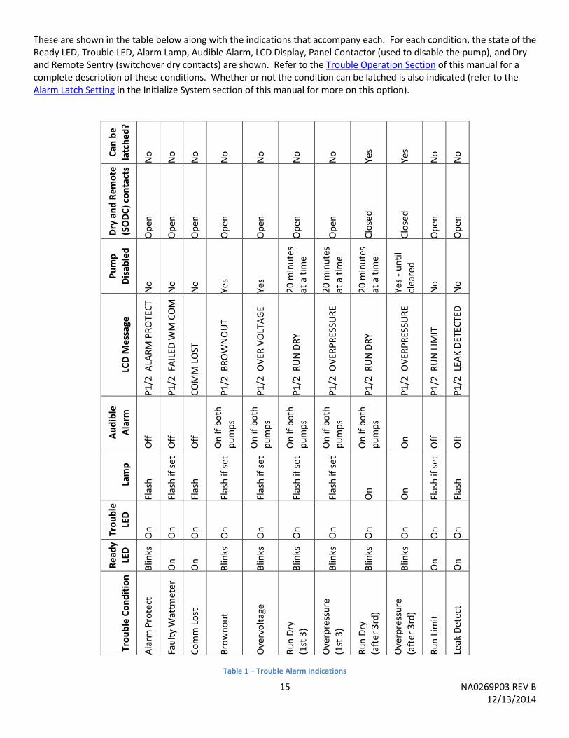
These are shown in the table below along with the indications that accompany each. For each condition, the state of the Ready LED, Trouble LED, Alarm Lamp, Audible Alarm, LCD Display, Panel Contactor (used to disable the pump), and Dry and Remote Sentry (switchover dry contacts) are shown. Refer to the Trouble Operation Section of this manual for a complete description of these conditions. Whether or not the condition can be latched is also indicated (refer to the Alarm Latch Setting in the Initialize System section of this manual for more on this option).
Can
be
latc
hed
?
No
No
No
No
No
No
No
Yes
Yes
No
No
Dry
an
d R
emo
te
(SO
DC
) co
nta
cts
Op
en
Op
en
Op
en
Op
en
Op
en
Op
en
Op
en
Clo
sed
Clo
sed
Op
en
Op
en
Pu
mp
Dis
able
d
No
No
No
Yes
Yes
20
min
ute
s
at a
tim
e
20
min
ute
s
at a
tim
e
20
min
ute
s
at a
tim
e
Yes
- u
nti
l
clea
red
No
No
LCD
Mes
sage
P1
/2 A
LAR
M P
RO
TEC
T
P1
/2 F
AIL
ED W
M C
OM
CO
MM
LO
ST
P1
/2 B
RO
WN
OU
T
P1
/2 O
VER
VO
LTA
GE
P1
/2 R
UN
DR
Y
P1
/2 O
VER
PR
ESSU
RE
P1
/2 R
UN
DR
Y
P1
/2 O
VER
PR
ESSU
RE
P1
/2 R
UN
LIM
IT
P1
/2 L
EAK
DET
ECTE
D
Au
dib
le
Ala
rm
Off
Off
Off
On
if b
oth
pu
mp
s
On
if b
oth
p
um
ps
On
if b
oth
pu
mp
s
On
if b
oth
pu
mp
s
On
if b
oth
p
um
ps
On
Off
Off
Lam
p
Flas
h
Flas
h if
se
t
Flas
h
Flas
h if
se
t
Flas
h if
set
Flas
h if
se
t
Flas
h if
se
t
On
On
Flas
h if
se
t
Flas
h
Tro
ub
le
LED
On
On
On
On
On
On
On
On
On
On
On
Re
ady
LED
Blin
ks
On
On
Blin
ks
Blin
ks
Blin
ks
Blin
ks
Blin
ks
Blin
ks
On
On
Tro
ub
le C
on
dit
ion
Ala
rm P
rote
ct
Fau
lty
Wat
tmet
er
Co
mm
Lo
st
Bro
wn
ou
t
Ove
rvo
ltag
e
Ru
n D
ry
(1st
3)
Ove
rpre
ssu
re
(1st
3)
Ru
n D
ry
(aft
er
3rd
)
Ove
rpre
ssu
re
(aft
er
3rd
)
Ru
n L
imit
Leak
Det
ect
Table 1 – Trouble Alarm Indications
16 NA0269P03 REV B 12/13/2014
7.4 Audible Alarm Manual Silence Anytime the audible alarm / buzzer is activated by the system, it can be silenced by pressing the ‘SILENCE’ button located on the exterior underside of the enclosure.
7.5 Pump Performance When power is first applied to the panel, the Normal Operation is the default mode, as indicated by the green LED adjacent to Normal Operation being illuminated. While in the Normal Operation Mode the real-time operating voltage and amperage of the lead pump will be displayed on the LCD screen simultaneously. Pressing the ‘Scroll’ button one time will display the real-time operating wattage. After each completed Pump Run cycle, all operating parameters are updated with the most recent data. If power is lost during a Pump Run cycle, only data for that cycle will be lost, all other data is maintained in non-volatile memory. Pressing the ‘Mode’ button until the LED adjacent to Pump Performance is illuminated will display several other system operating parameters. The following are displayed under Pump Performance:
7.5.1 Pump 1 / 2 This field allows choosing which pumps operating parameters will be displayed. From the Display: Pump 1/2? screen, use the ↑ ‘A’ and ↓ ‘B’ keys to change the selection from ‘PUMP 1?’ to ‘PUMP 2?’. Once the desired pump is selected, press ‘Enter’ to accept. By default the parameters for Pump 1 will be displayed. The LCD will display ‘Retrieving…’, after which the following parameters for the chosen pump will be displayed.
7.5.2 Normal Hour Meter Accumulated runtime - The time is displayed as Run: HH:MM:SS, where HH are the total hours, MM minutes, and SS seconds since the last reset. The maximum runtime value that can be stored is 999999:59:59 (> 114 years). Beyond this limit the value automatically resets to 00:00:00.
7.5.3 Normal Cycle Counter Accumulated cycles - The value is displayed as Cycles: XX, where XX are the total accumulated pump cycles since the last reset. The maximum cycle value that can be stored is 1 billion. Beyond this limit the value automatically resets to 0.
7.5.4 Manual Run Hour Meter Accumulated Manual Run runtime - For service and troubleshooting purposes, the Manual Run hours are tracked separately from normal hours. This value is displayed as MR: HH:MM:SS and has the same limits as the normal hours.
7.5.5 Manual Run Cycle Counter Accumulated Manual Run cycles - For service and troubleshooting purposes, the Manual Run cycles are tracked separately from normal cycles. This value is displayed as MR Cycles: XX and has the same limits as the normal cycles.
7.5.6 Last Runtime Last runtime represents the duration of the previous completed pump cycle. This value is displayed as Last Run: XXXs, where XXX is the last runtime duration in seconds.
7.5.7 Minimum Runtime The minimum runtime represents the duration of the shortest completed pump cycle since the last reset. This value is displayed as Min Run: XXXs, where XXX is the minimum runtime duration in seconds.
7.5.8 Maximum Runtime The maximum runtime represents the duration of the longest completed pump cycle since the last reset. This value is displayed as Max Run:HH:MM:SS and has the same limits as the normal hours.
7.5.9 Average Runtime The average runtime represents the duration of the average completed pump cycle since the last reset. This value is displayed as Ave Run: XXXs where XXX is the average runtime duration in seconds.
17 NA0269P03 REV B 12/13/2014
7.5.10 Minimum Amps The minimum Amperage reading represents the minimum amperage draw the motor has experienced while running since the last reset. This value is displayed as Min Amps: X.XA where X.X is the minimum Amperage to the nearest tenth.
7.5.11 Maximum Amps The maximum Amperage reading represents the maximum amperage draw the motor has experienced while running since the last reset. This value is displayed as Max Amps: X.XA where X.X is the maximum Amperage to the nearest tenth.
7.5.12 Average Amps The average Amperage reading represents the average amperage draw the motor has experienced while running since the last reset. This value is displayed as Ave Amps: X.XA where X.X is the average Amperage to the nearest tenth.
7.5.13 Minimum Volts The minimum Voltage reading represents the minimum voltage the motor has experienced while running since the last reset. This value is displayed as Min Volts: XV where X is the minimum Voltage to the nearest volt.
7.5.14 Maximum Volts The maximum Voltage reading represents the maximum voltage the motor has experienced while running since the last reset. This value is displayed as Max Volts: XV where X is the maximum Voltage to the nearest volt.
7.5.15 Average Volts The average Voltage reading represents the average voltage the motor has experienced while running since the last reset. This value is displayed as Ave Volts: XV where X is the average Voltage to the nearest volt.
7.5.16 Minimum Watts The minimum Wattage reading represents the minimum Wattage the motor has experienced while running since the last reset. This value is displayed as Min Watts: XW where X is the minimum Wattage to the nearest watt.
7.5.17 Maximum Watts The next maximum Wattage reading represents the maximum Wattage the motor has experienced while running since the last reset. This value is displayed as Max Watts: XW where X is the maximum Wattage to the nearest watt.
7.5.18 Average Watts The average Wattage reading represents the average Wattage the motor has experienced while running since the last reset. This value is displayed as Ave Watts: XW where X is the average Wattage to the nearest watt.
7.5.19 Leak Detected (read-only leak indication field, E/One explosion proof pumps only) This option does not apply to hardwired pumps. Contact E/One for more information.
7.5.20 Clear Counters (cycles, hour meters, averages) The clear counters option can be used to clear the following pump parameters: Normal Hours, Normal Cycle Counter, Manual Run Hours, Manual Run Cycle Counter, Last Run Time, Average Volts, Average Amps and Average Watts. From the Clear Counters menu, use the ↑ ‘A’ and ↓ ‘B’ keys to alternate the selection between ‘N’ (no) and ‘Y’ (yes). Once ‘Y‘ is selected, pressing ‘Enter’ will clear the stored values.
7.5.21 Clear Minimums and Maximums The clear minimum and maximum option can be used to clear the following pump parameters: Minimum and Maximum Volts, Minimum and Maximum Amps, Minimum and Maximum Watts, and Minimum and Maximum Run Time. From the Clear Min/Max menu, use the ↑ ‘A’ and ↓ ‘B’ keys to alternate the selection between ‘N’ (no) and ‘Y’ (yes). Once ‘Y‘ is selected, pressing ‘Enter’ will clear the stored values.
18 NA0269P03 REV B 12/13/2014
7.5.22 Clock Error The clock error field indicates that there is a problem with the board’s microprocessor timing. If this is the case, this field will display ‘Clock Error: 1’, otherwise it will show ‘Clock Error: 0’. This is a self-clearing error. If this field is set to a ‘1’, factory service should be contacted. This condition does not result in a trouble indication or LCD message and can only be verified by navigating to the Clock Error field within the Pump Performance mode.
8 Trouble Operation Several less serious operating conditions can be detected and indicated to warn of pending, more serious faults. These conditions do not warrant an immediate response and may clear themselves given time. Refer to Table 1 in the Trouble Alarm Indication section of this manual for a list of these conditions and the indications that result from each. As indicated, the Alarm Lamp can be set to flash for some of these cases by setting the Trouble Mode option (refer to the Trouble Mode option under the User Programmable Options section of this manual for more on this feature).
8.1 Excessive Runtime Operation Excessive Runtime is an alarm that is initiated if an individual pump run cycle exceeds the set Run Limit value. If the Run Limit is exceeded, the panel will indicate a trouble alarm as determined by the Alarm Mode setting. In addition, the amber Trouble LED will light and a corresponding error message will be displayed on the LCD screen for the individual pump (P1/P2) which experienced the excessive run time. This alarm serves only as a visual indicator that this limit has been exceeded; operation of the pump is not affected.
8.2 Brownout Operation Brownout is a motor protection feature that will disable power to the motor if the incoming AC Mains Voltage is below a predefined limit, typically 12% of the nominal nameplate rating. In the brownout mode, the pump is prevented from starting (if the pump is off), or is shut off (if the pump is running) until the voltage returns to within the desired range of operation, typically 10% of the nominal nameplate rating. When in the Brownout Protection mode, the panel will disable power to the pump, whether the motor is running or not and indicate a trouble alarm as determined by the Alarm Mode setting. In addition, the amber Trouble LED will light and a corresponding error message will be displayed on the LCD screen.
8.3 Overvoltage Operation Overvoltage is a motor protection feature that will disable power to the motor if the incoming AC Mains Voltage is above a predefined limit, typically 12% of the nominal nameplate rating. In the Overvoltage mode, the pump is prevented from starting (if the pump is off), or is shut off (if the pump is running) until the voltage returns to within the desired range of operation, typically 10% of the nominal nameplate rating. When in the Overvoltage Protection mode, the panel will disable power to the pump, whether the motor is running or not and indicate a trouble alarm as determined by the Alarm Mode setting. In addition, the amber Trouble LED will light and a corresponding error message will be displayed on the LCD screen.
8.4 Run Dry Operation Run Dry is a motor protection feature that will disable power to the motor if the power consumption falls below a predefined limit. The factory default limit is based on the DIP switch settings and may vary for different locations. Refer to the Run Dry (Low Watts) menu within the Initialize System mode to see what the current value for this setting is. Contact E/One if you require more information on this setting. This limit is affected by the incoming AC Mains Voltage; as the Voltage fluctuates from nominal, this limit is automatically adjusted in order to obtain the same perceived pump power as would be seen at nominal Voltage. In addition, this value can be changed under direction of the factory to accommodate various system variables. When a Run Dry condition is detected, the pump is shut off and a 20 minute lockout period begins. During this time, the Trouble LED is illuminated, the Run Dry error message is displayed on the LCD and the pump is not allowed to run. After the 20 minute lockout, the pump is allowed to run; if the Run Dry condition is still present, a second lockout period begins and the cycle will repeat. During the first three lockout periods, the panel will indicate a Trouble Alarm (refer to the Trouble Alarm option within the Normal Operation section of this manual for more information on this feature). If after the third lockout period (60 minutes) the condition has not been removed and the pump attempts to start, the panel will indicate an alarm condition including the Alarm Lamp, Trouble
19 NA0269P03 REV B 12/13/2014
LED, Dry and Remote Sentry contacts, but no Audible Alarm. The pump is retested every 20 minutes indefinitely and will self-clear if a full pump cycle completes under normal conditions. If a High Level Alarm is detected at any time during the lockout sequence, the panel will respond by issuing a Delayed high level alarm, energizing BOTH pumps contactors and allowing both pumps to run. Refer to the Delayed Alarm section for more information. It is assumed that if a high level alarm is present, despite the Run Dry condition there is liquid in the tank and a high level alarm is necessary. In a Run Dry condition, the 20 minute lockout period can be bypassed by pressing the Manual Run button (‘Enter’). This should only be performed by E/One Certified Service Personnel.
8.5 Overpressure Operation Overpressure is a motor protection feature that will disable power to the motor if the power consumption rises above a predefined limit. The factory default limit is based on the DIP switch settings and may vary for different locations. Refer to the Overpressure (Hi Watts) menu within the Initialize System mode to see what the current value for this setting is. This limit can be changed under direction of the factory to accommodate various system variables. When an Overpressure condition is detected, the pump is shut off and a 20 minute lockout period begins. During this time, the Trouble LED is illuminated, the Overpressure error message is displayed on the LCD and the pump is not allowed to run regardless of the liquid level in the tank. After the 20 minute lockout, the pump is allowed to run; if the Overpressure condition is still present a second lockout period begins, and the cycle will repeat. During the first three lockout periods, the panel will indicate a Trouble Alarm (refer to the Trouble Alarm option within the Normal Operation section of this manual for more information on this feature). If after the third lockout period (60 minutes) the condition has not been removed and the pump attempts to start, the panel will indicate an alarm condition including the Alarm Lamp, Trouble LED, Dry and Remote Sentry contacts, and Audible Alarm. In addition, unlike for a Run Dry condition, in Overpressure the pump will not be retested every 20 minutes indefinitely because of the buildup of pressure that occurs during each retest. After the third failed retry, the pump is disabled indefinitely until it can be serviced. If a High Level Alarm is detected at any time during the lockout sequence, the panel will respond by issuing a Delayed high level alarm, energizing BOTH pumps contactors and allowing both pumps to run. Refer to the High Level Alarm section for more information. In an Overpressure condition, the 20 minute lockout period can be bypassed by pressing the Manual Run button (‘Enter’). This should only be performed by E/One Certified Service Personnel.
8.6 Alarm Circuit Protection Active The circuit board contains circuitry to help limit any permanent damage due to a mis-wire or short within the alarm pressure switch circuit. While this does not guarantee protection in all cases, if activated, this feature acts as a resettable fuse and will temporarily open the circuit to help prevent damage to the circuit board itself. If conditions warrant and this circuit has been activated, the panel will be unable to detect if the alarm pressure switch is closed. This condition will be indicated by a blinking Ready LED, steady Trouble LED, flashing alarm lamp and a corresponding message displayed on the LCD screen.
8.7 Faulty Watt-meter Operation A faulty watt-meter indicates that the Protect Plus Panel has lost its ability to detect any of the following conditions: Brownout, Overvoltage, Run Dry, and Overpressure. This will be indicated with the amber Trouble LED and a corresponding error message displayed on the LCD screen. If this condition is present, contact E/One service personnel. While the pumps will still operate in this mode, there is no ability to detect if any of these conditions are present; damage to the pump and/or system could occur.
8.8 Comm Lost Indication This error indicates that the communication link between the two individual circuit boards that make up the E/One Sentry Protect Plus Duplex Panel is not functioning properly. In this situation, the circuit boards revert to two individual Simplex circuit boards and operate as such. If this condition is present, contact E/One service personnel. While the pumps will still operate in this mode, the system will not operate efficiently for a Duplex application.
20 NA0269P03 REV B 12/13/2014
8.9 Leak Detect Operation (E/One explosion proof pumps only) This option does not apply to hardwired pumps and should be left in the default (OFF) setting. Contact E/One for more information.
9 Diagnostics The panel is equipped with a diagnostic tool to verify that all outputs are operational. These tests are available from the Diagnostic Mode and are divided into 3 categories. These categories can be selected using the ‘Scroll’ button.
9.1 LED Test The first diagnostic test verifies operation of all LED’s on the dead front overlay. The top four LED’s will light in sequence and remain lit. The bottom 8 LED’s will sequence one after the other and repeat. If any LED does not light during this test, consider having the dead front or panel serviced. Press ‘Scroll’ to move to the next test.
9.2 Button Test The next diagnostic test verifies that all of the buttons on the dead front overlay work and can be detected by the panel. Pressing each button should result in that buttons name / function being displayed on the LCD screen. If any button does not register on the LCD display, consider having the dead front or panel serviced. For this test, pressing ‘Scroll’ will move to the next test, so it is suggested to verify this button last.
9.3 Relay Test
Warning! The system is taken off-line during the relay test and will be unable to respond to a high level alarm and may prevent the pump from running. Be sure to exit this feature and ensure the Ready LED is lit prior to leaving the station.
The last diagnostic test verifies the operation of all control relays. This includes the Manual Run relay, Alarm Lamp relay, Audible Alarm relay, Dry and Remote Sentry Contacts relay, and the Panel Contactor Coil relay. The test allows each board to independently cycle the associated relays to verify both circuit boards are operational. Use the ‘Scroll’ button to select each relay individually, then the ↑ ‘A’ and ↓ ‘B’ buttons can be used to alternate the state of the selected output. Each output can then be verified for proper operation individually. If any relay does not operate as expected the panel should be serviced. Press ‘Scroll’ to repeat the diagnostic test, or ‘Mode’ to exit.
10 Communication The Duplex Protect Plus Panel can be read by an external device to provide system operating parameters for continuous system monitoring and predictive maintenance.
Except for the Data Push feature (refer to the Data Push option within the User Programmable Options section of this manual for more information on this feature), the panel is not able to initiate any communication and relies on an external device to read data. In addition, the circuit board itself does not provide any electrical isolation between external connections and the board circuitry itself. Special care is required when configuring your system to prevent transients and the like from causing damage to the communication interface. These interfaces are intended to communicate locally with a standalone transceiver device that provides the interface to the outside world.
The panel uses a Modbus communication protocol with the following parameters:
Modbus Type RTU
Device Address 16
Base Register Offset 0
Baud Rate 9600
Data Bits 8 Bits
Parity None
Stop Bits 1
21 NA0269P03 REV B 12/13/2014
10.1 Serial Interface All panels can be configured with an RS-232 serial interface that can be used to read system registers. An optional Serial Interface Adaptor with a DB9 connector is provided on the dead front to allow connecting to a PC or other mobile device. Optional board configurations can provide an RS-485 interface. A complete list of available parameters and their register locations can be found in the System Parameters Memory Map section of the Appendix at the back of this manual. Note that some registers are for internal purposes only and may not be useful to the end user. Please contact E/One for more information or to discuss your specific requirements.
10.2 Sentry Advisor Option All panels can be updated to allow communication using the optional Sentry Advisor Remote Monitoring System. With the proper board configuration and operating software, the panel can be remotely monitored for various system operating parameters. Refer to E/One document NA0451P01 – ‘Sentry Advisor Remote Monitoring System Operation Manual’ for a complete description of the features of this system. Contact E/One Customer Service for more information on compatibility of this option with existing panels.
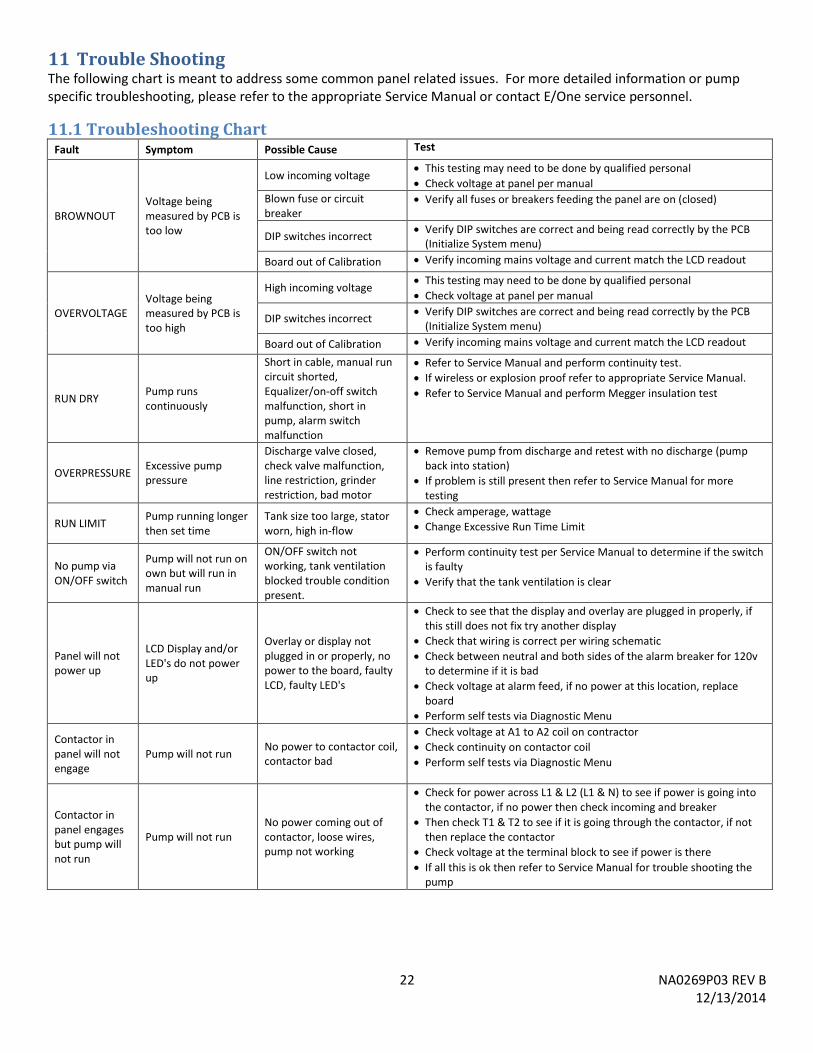
22 NA0269P03 REV B 12/13/2014
11 Trouble Shooting The following chart is meant to address some common panel related issues. For more detailed information or pump specific troubleshooting, please refer to the appropriate Service Manual or contact E/One service personnel.
11.1 Troubleshooting Chart Fault Symptom Possible Cause Test
BROWNOUT Voltage being measured by PCB is too low
Low incoming voltage This testing may need to be done by qualified personal
Check voltage at panel per manual
Blown fuse or circuit breaker
Verify all fuses or breakers feeding the panel are on (closed)
DIP switches incorrect Verify DIP switches are correct and being read correctly by the PCB
(Initialize System menu)
Board out of Calibration Verify incoming mains voltage and current match the LCD readout
OVERVOLTAGE Voltage being measured by PCB is too high
High incoming voltage This testing may need to be done by qualified personal
Check voltage at panel per manual
DIP switches incorrect Verify DIP switches are correct and being read correctly by the PCB
(Initialize System menu)
Board out of Calibration Verify incoming mains voltage and current match the LCD readout
RUN DRY Pump runs continuously
Short in cable, manual run circuit shorted, Equalizer/on-off switch malfunction, short in pump, alarm switch malfunction
Refer to Service Manual and perform continuity test.
If wireless or explosion proof refer to appropriate Service Manual.
Refer to Service Manual and perform Megger insulation test
OVERPRESSURE Excessive pump pressure
Discharge valve closed, check valve malfunction, line restriction, grinder restriction, bad motor
Remove pump from discharge and retest with no discharge (pump back into station)
If problem is still present then refer to Service Manual for more testing
RUN LIMIT Pump running longer then set time
Tank size too large, stator worn, high in-flow
Check amperage, wattage
Change Excessive Run Time Limit
No pump via ON/OFF switch
Pump will not run on own but will run in manual run
ON/OFF switch not working, tank ventilation blocked trouble condition present.
Perform continuity test per Service Manual to determine if the switch is faulty
Verify that the tank ventilation is clear
Panel will not power up
LCD Display and/or LED's do not power up
Overlay or display not plugged in or properly, no power to the board, faulty LCD, faulty LED's
Check to see that the display and overlay are plugged in properly, if this still does not fix try another display
Check that wiring is correct per wiring schematic
Check between neutral and both sides of the alarm breaker for 120v to determine if it is bad
Check voltage at alarm feed, if no power at this location, replace board
Perform self tests via Diagnostic Menu
Contactor in panel will not engage
Pump will not run No power to contactor coil, contactor bad
Check voltage at A1 to A2 coil on contractor
Check continuity on contactor coil
Perform self tests via Diagnostic Menu
Contactor in panel engages but pump will not run
Pump will not run No power coming out of contactor, loose wires, pump not working
Check for power across L1 & L2 (L1 & N) to see if power is going into the contactor, if no power then check incoming and breaker
Then check T1 & T2 to see if it is going through the contactor, if not then replace the contactor
Check voltage at the terminal block to see if power is there
If all this is ok then refer to Service Manual for trouble shooting the pump
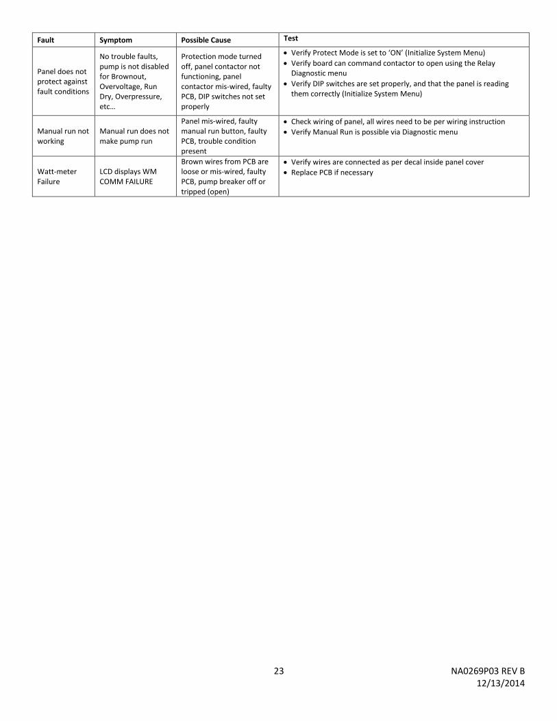
23 NA0269P03 REV B 12/13/2014
Fault Symptom Possible Cause Test
Panel does not protect against fault conditions
No trouble faults, pump is not disabled for Brownout, Overvoltage, Run Dry, Overpressure, etc…
Protection mode turned off, panel contactor not functioning, panel contactor mis-wired, faulty PCB, DIP switches not set properly
Verify Protect Mode is set to ‘ON’ (Initialize System Menu)
Verify board can command contactor to open using the Relay Diagnostic menu
Verify DIP switches are set properly, and that the panel is reading them correctly (Initialize System Menu)
Manual run not working
Manual run does not make pump run
Panel mis-wired, faulty manual run button, faulty PCB, trouble condition present
Check wiring of panel, all wires need to be per wiring instruction
Verify Manual Run is possible via Diagnostic menu
Watt-meter Failure
LCD displays WM COMM FAILURE
Brown wires from PCB are loose or mis-wired, faulty PCB, pump breaker off or tripped (open)
Verify wires are connected as per decal inside panel cover
Replace PCB if necessary
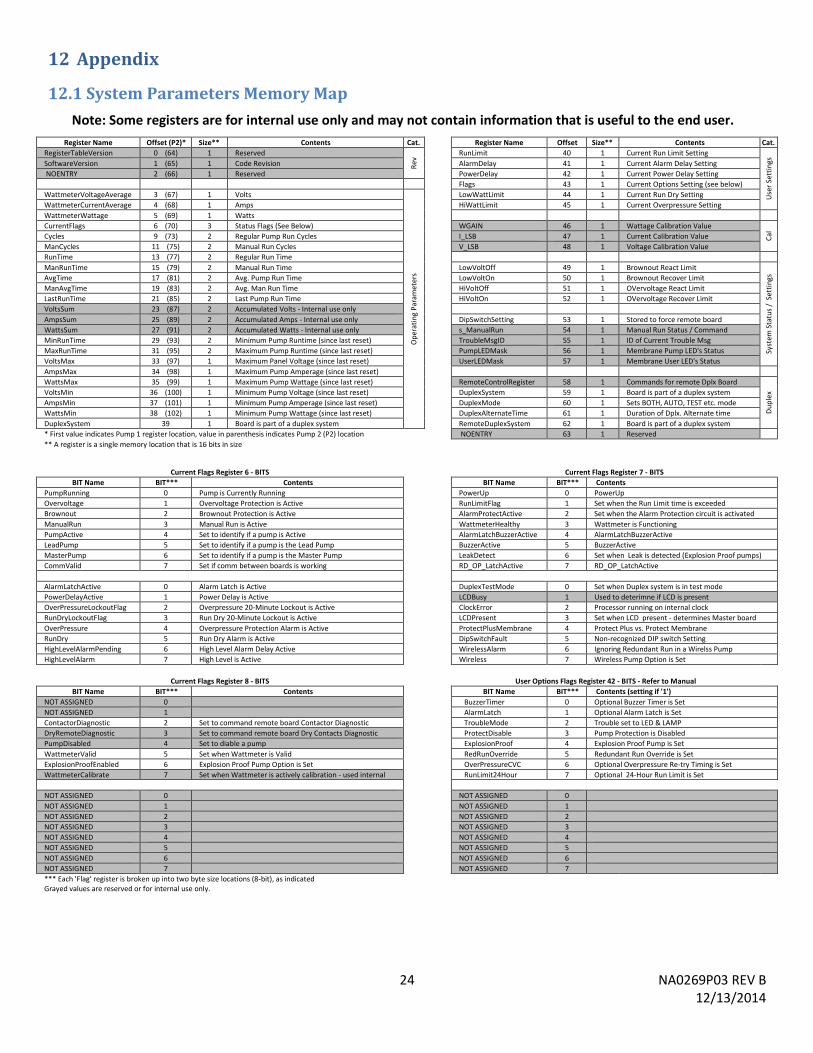
24 NA0269P03 REV B 12/13/2014
12 Appendix
12.1 System Parameters Memory Map
Note: Some registers are for internal use only and may not contain information that is useful to the end user.
Register Name Offset (P2)* Size** Contents Cat.
Register Name Offset Size** Contents Cat.
RegisterTableVersion 0 (64) 1 Reserved
Rev
RunLimit 40 1 Current Run Limit Setting
Use
r Se
ttin
gs
SoftwareVersion 1 (65) 1 Code Revision
AlarmDelay 41 1 Current Alarm Delay Setting
NOENTRY 2 (66) 1 Reserved
PowerDelay 42 1 Current Power Delay Setting
Flags 43 1 Current Options Setting (see below)
WattmeterVoltageAverage 3 (67) 1 Volts
Op
erat
ing
Par
ame
ters
LowWattLimit 44 1 Current Run Dry Setting
WattmeterCurrentAverage 4 (68) 1 Amps
HiWattLimit 45 1 Current Overpressure Setting
WattmeterWattage 5 (69) 1 Watts
CurrentFlags 6 (70) 3 Status Flags (See Below)
WGAIN 46 1 Wattage Calibration Value
Cal
Cycles 9 (73) 2 Regular Pump Run Cycles
I_LSB 47 1 Current Calibration Value
ManCycles 11 (75) 2 Manual Run Cycles
V_LSB 48 1 Voltage Calibration Value
RunTime 13 (77) 2 Regular Run Time
ManRunTime 15 (79) 2 Manual Run Time
LowVoltOff 49 1 Brownout React Limit
Syst
em S
tatu
s /
Set
tin
gs
AvgTime 17 (81) 2 Avg. Pump Run Time
LowVoltOn 50 1 Brownout Recover Limit
ManAvgTime 19 (83) 2 Avg. Man Run Time
HiVoltOff 51 1 OVervoltage React Limit
LastRunTime 21 (85) 2 Last Pump Run Time
HiVoltOn 52 1 OVervoltage Recover Limit
VoltsSum 23 (87) 2 Accumulated Volts - Internal use only
AmpsSum 25 (89) 2 Accumulated Amps - Internal use only
DipSwitchSetting 53 1 Stored to force remote board
WattsSum 27 (91) 2 Accumulated Watts - Internal use only
s_ManualRun 54 1 Manual Run Status / Command
MinRunTime 29 (93) 2 Minimum Pump Runtime (since last reset)
TroubleMsgID 55 1 ID of Current Trouble Msg
MaxRunTime 31 (95) 2 Maximum Pump Runtime (since last reset)
PumpLEDMask 56 1 Membrane Pump LED's Status
VoltsMax 33 (97) 1 Maximum Panel Voltage (since last reset)
UserLEDMask 57 1 Membrane User LED's Status
AmpsMax 34 (98) 1 Maximum Pump Amperage (since last reset)
WattsMax 35 (99) 1 Maximum Pump Wattage (since last reset)
RemoteControlRegister 58 1 Commands for remote Dplx Board
Du
ple
x VoltsMin 36 (100) 1 Minimum Pump Voltage (since last reset)
DuplexSystem 59 1 Board is part of a duplex system
AmpsMin 37 (101) 1 Minimum Pump Amperage (since last reset)
DuplexMode 60 1 Sets BOTH, AUTO, TEST etc. mode
WattsMin 38 (102) 1 Minimum Pump Wattage (since last reset)
DuplexAlternateTime 61 1 Duration of Dplx. Alternate time
DuplexSystem 39 1 Board is part of a duplex system
RemoteDuplexSystem 62 1 Board is part of a duplex system
* First value indicates Pump 1 register location, value in parenthesis indicates Pump 2 (P2) location
NOENTRY 63 1 Reserved ** A register is a single memory location that is 16 bits in size
Current Flags Register 6 - BITS
Current Flags Register 7 - BITS
BIT Name BIT*** Contents
BIT Name BIT*** Contents
PumpRunning 0 Pump is Currently Running
PowerUp 0 PowerUp
Overvoltage 1 Overvoltage Protection is Active
RunLimitFlag 1 Set when the Run Limit time is exceeded
Brownout 2 Brownout Protection is Active
AlarmProtectActive 2 Set when the Alarm Protection circuit is activated
ManualRun 3 Manual Run is Active
WattmeterHealthy 3 Wattmeter is Functioning
PumpActive 4 Set to identify if a pump is Active
AlarmLatchBuzzerActive 4 AlarmLatchBuzzerActive
LeadPump 5 Set to identify if a pump is the Lead Pump
BuzzerActive 5 BuzzerActive
MasterPump 6 Set to identify if a pump is the Master Pump
LeakDetect 6 Set when Leak is detected (Explosion Proof pumps)
CommValid 7 Set if comm between boards is working
RD_OP_LatchActive 7 RD_OP_LatchActive
AlarmLatchActive 0 Alarm Latch is Active
DuplexTestMode 0 Set when Duplex system is in test mode
PowerDelayActive 1 Power Delay is Active
LCDBusy 1 Used to deterimne if LCD is present
OverPressureLockoutFlag 2 Overpressure 20-Minute Lockout is Active
ClockError 2 Processor running on internal clock
RunDryLockoutFlag 3 Run Dry 20-Minute Lockout is Active
LCDPresent 3 Set when LCD present - determines Master board
OverPressure 4 Overpressure Protection Alarm is Active
ProtectPlusMembrane 4 Protect Plus vs. Protect Membrane
RunDry 5 Run Dry Alarm is Active
DipSwitchFault 5 Non-recognized DIP switch Setting
HighLevelAlarmPending 6 High Level Alarm Delay Active
WirelessAlarm 6 Ignoring Redundant Run in a Wirelss Pump
HighLevelAlarm 7 High Level is Active
Wireless 7 Wireless Pump Option is Set
Current Flags Register 8 - BITS
User Options Flags Register 42 - BITS - Refer to Manual BIT Name BIT*** Contents
BIT Name BIT*** Contents (setting if '1')
NOT ASSIGNED 0
BuzzerTimer 0 Optional Buzzer Timer is Set
NOT ASSIGNED 1
AlarmLatch 1 Optional Alarm Latch is Set
ContactorDiagnostic 2 Set to command remote board Contactor Diagnostic
TroubleMode 2 Trouble set to LED & LAMP
DryRemoteDiagnostic 3 Set to command remote board Dry Contacts Diagnostic
ProtectDisable 3 Pump Protection is Disabled
PumpDisabled 4 Set to diable a pump
ExplosionProof 4 Explosion Proof Pump is Set
WattmeterValid 5 Set when Wattmeter is Valid
RedRunOverride 5 Redundant Run Override is Set
ExplosionProofEnabled 6 Explosion Proof Pump Option is Set
OverPressureCVC 6 Optional Overpressure Re-try Timing is Set
WattmeterCalibrate 7 Set when Wattmeter is actively calibration - used internal
RunLimit24Hour 7 Optional 24-Hour Run Limit is Set
NOT ASSIGNED 0
NOT ASSIGNED 0
NOT ASSIGNED 1
NOT ASSIGNED 1
NOT ASSIGNED 2
NOT ASSIGNED 2
NOT ASSIGNED 3
NOT ASSIGNED 3
NOT ASSIGNED 4
NOT ASSIGNED 4
NOT ASSIGNED 5
NOT ASSIGNED 5
NOT ASSIGNED 6
NOT ASSIGNED 6
NOT ASSIGNED 7
NOT ASSIGNED 7
*** Each 'Flag' register is broken up into two byte size locations (8-bit), as indicated Grayed values are reserved or for internal use only.
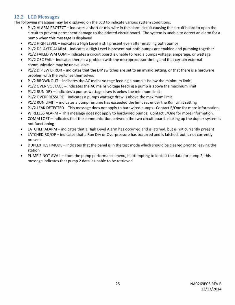
25 NA0269P03 REV B 12/13/2014
12.2 LCD Messages The following messages may be displayed on the LCD to indicate various system conditions.
P1/2 ALARM PROTECT – indicates a short or mis-wire in the alarm circuit causing the circuit board to open the circuit to prevent permanent damage to the printed circuit board. The system is unable to detect an alarm for a pump when this message is displayed
P1/2 HIGH LEVEL – indicates a High Level is still present even after enabling both pumps
P1/2 DELAYED ALARM – indicates a High Level is present but both pumps are enabled and pumping together
P1/2 FAILED WM COM – indicates a circuit board is unable to read a pumps voltage, amperage, or wattage
P1/2 OSC FAIL – indicates there is a problem with the microprocessor timing and that certain external communication may be unavailable
P1/2 DIP SW ERROR – indicates that the DIP switches are set to an invalid setting, or that there is a hardware problem with the switches themselves
P1/2 BROWNOUT – indicates the AC mains voltage feeding a pump is below the minimum limit
P1/2 OVER VOLTAGE – indicates the AC mains voltage feeding a pump is above the maximum limit
P1/2 RUN DRY – indicates a pumps wattage draw is below the minimum limit
P1/2 OVERPRESSURE – indicates a pumps wattage draw is above the maximum limit
P1/2 RUN LIMIT – indicates a pump runtime has exceeded the limit set under the Run Limit setting
P1/2 LEAK DETECTED – This message does not apply to hardwired pumps. Contact E/One for more information.
WIRELESS ALARM – This message does not apply to hardwired pumps. Contact E/One for more information.
COMM LOST – indicates that the communication between the two circuit boards making up the duplex system is not functioning
LATCHED ALARM – indicates that a High Level Alarm has occurred and is latched, but is not currently present
LATCHED RD/OP – indicates that a Run Dry or Overpressure has occurred and is latched, but is not currently present
DUPLEX TEST MODE – indicates that the panel is in the test mode which should be cleared prior to leaving the station
PUMP 2 NOT AVAIL – from the pump performance menu, if attempting to look at the data for pump 2, this message indicates that pump 2 data is unable to be retrieved
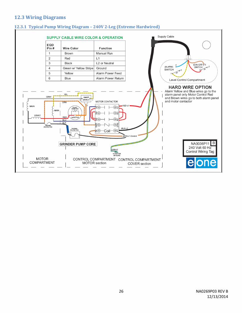
26 NA0269P03 REV B 12/13/2014
12.3 Wiring Diagrams
12.3.1 Typical Pump Wiring Diagram – 240V 2-Leg (Extreme Hardwired)
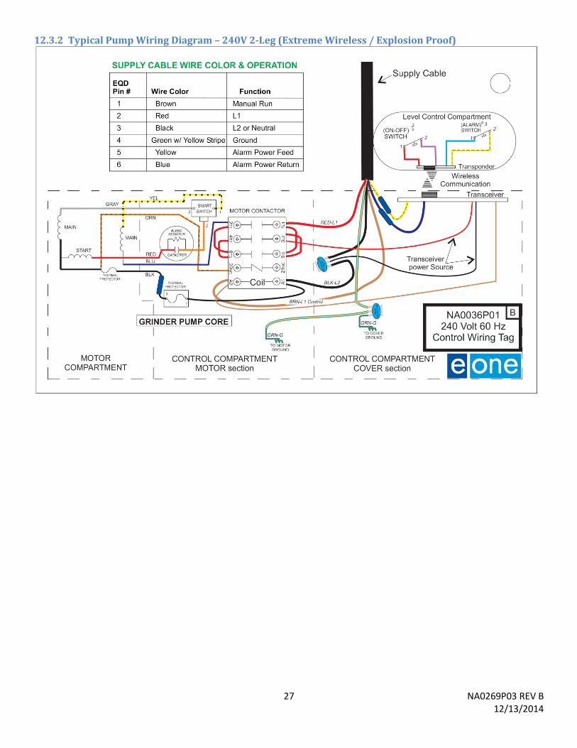
27 NA0269P03 REV B 12/13/2014
12.3.2 Typical Pump Wiring Diagram – 240V 2-Leg (Extreme Wireless / Explosion Proof)
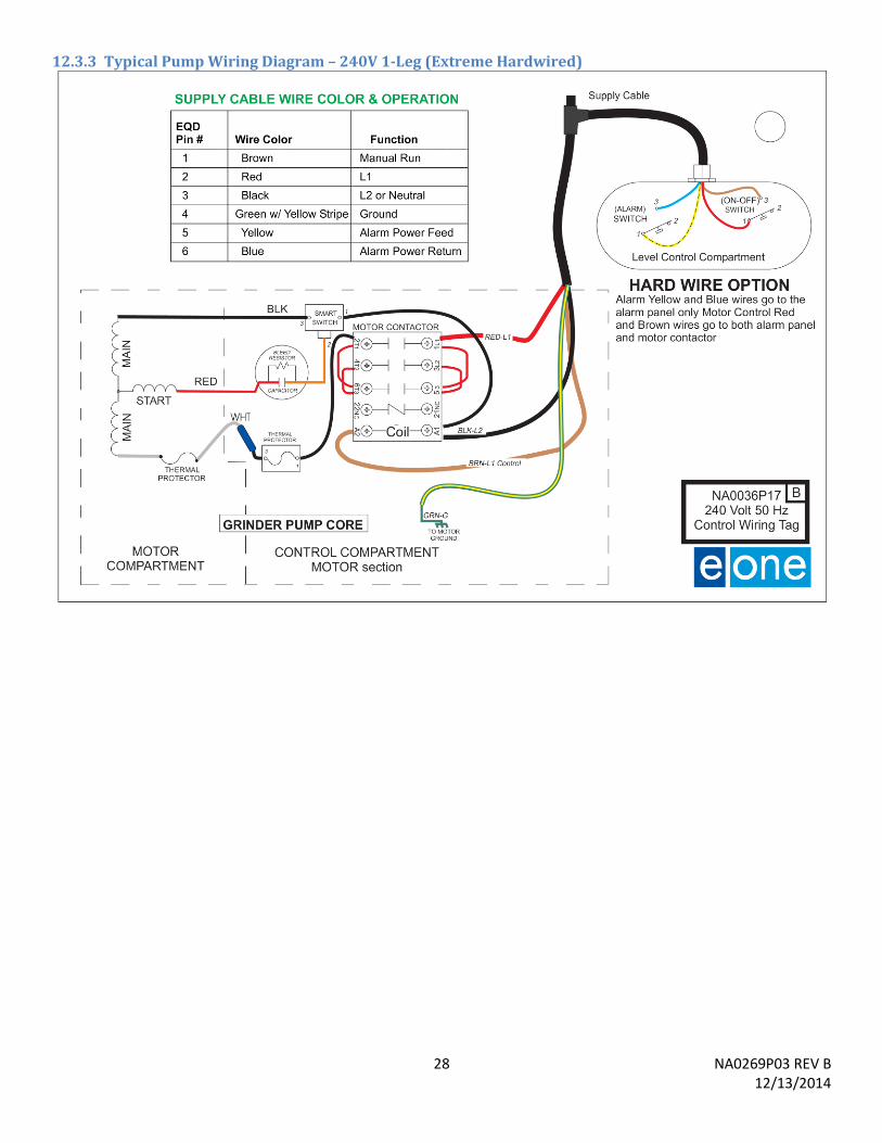
28 NA0269P03 REV B 12/13/2014
12.3.3 Typical Pump Wiring Diagram – 240V 1-Leg (Extreme Hardwired)
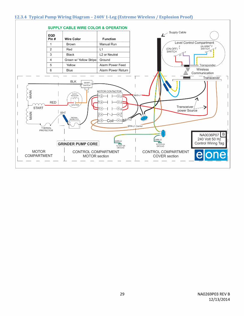
29 NA0269P03 REV B 12/13/2014
12.3.4 Typical Pump Wiring Diagram – 240V 1-Leg (Extreme Wireless / Explosion Proof)
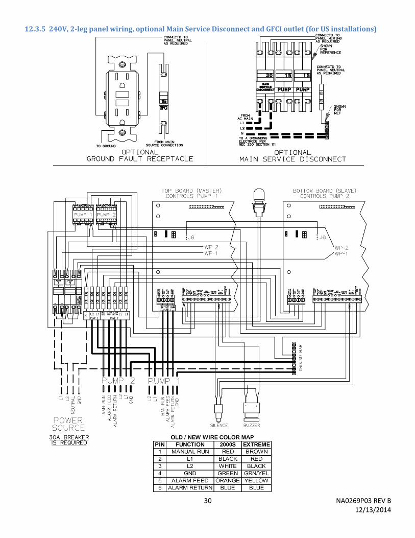
30 NA0269P03 REV B 12/13/2014
12.3.5 240V, 2-leg panel wiring, optional Main Service Disconnect and GFCI outlet (for US installations)
31 NA0269P03 REV B 12/13/2014
12.3.6 240V, 1-leg basic panel wiring (for non-US installations)

32 NA0269P03 REV B 12/13/2014
A Precision Castparts Company
Environment One Corporation 2773 Balltown Road Niskayuna, New York 12309–1090 Voice: (01) 518.346.6161 Fax: 518.346.6188 www.eone.com


![cf}Bf]lus gLlt, @)^&cf}Bf]lus gLlt, @)^&](https://img.pdfslide.net/doc/110x75/61d3d27b0940b1497a02780c/cfbflus-gllt-ampcfbflus-gllt-amp.jpg)

![Stim ⋅ u ⋅ lus stim ⋅ u ⋅ lus stim ⋅ u ⋅ lus – n. [stim-yuh-luhs]](https://img.pdfslide.net/doc/110x75/56649de75503460f94ae17ef/stim-u-lus-stim-u-lus-stim-u-lus-n-stim-yuh-luhs.jpg)