Embed Size (px)
Citation preview
Replacement Parts List No. 700000900Revision F 11/2016
To find your Daikin Applied parts distributor, call 1-800-377-2787 or visit www.DaikinApplied.com
DaikinMcQuay
Centrifugal ChillerDual Compressor
WDC, TDC, HDC100
RPL 7000009 / Page 2Centrifugal; WDC/TDC/HDC Size 100 Rev. F 11/16
ContentsParts List Revision History.................................................................................................................................. 3Electrical Legend ................................................................................................................................................ 4Nomenclature Nameplate Locations and Part Numbers ..................................................................................................... 5 Unit Dataplate, Model Number- Unit, Style Number- Unit, Serial Number- Unit .......................................... 6 Model Number- Complete ......................................................................................................................7 - 11Control Box- MicroTech 200 Mounting of Unit Control Panels ................................................................................................................ 12 Front Panel & Inside of Micro Control Door Assembly ............................................................................... 13 Interior Panel ....................................................................................................................................... 14 - 15 Sensors ...................................................................................................................................................... 16 Cables & Lube Box Tubing ................................................................................................................. 17 - 18 Mounting of Lube Boxes ............................................................................................................................ 19 Lube Box Assembly- Oil Pump .......................................................................................................... 20 - 21Control Box- MicroTech II Unit Control Box Mounting Components .................................................................................................... 22 Unit Control Box Detail - Until 5/05 ..................................................................................................... 23 - 24 Unit Control Box Detail- 5/05 to 6/11 .......................................................................................................... 25 Unit Control Box Detail- 6/11 and Later............................................................................................... 26 - 27 Compressor Control Box Mounting Components ...................................................................................... 28 Compressor Control Box Detail- Until 6/11 ......................................................................................... 29 - 30 Compressor Control Box Detail- 6/11 and Later ................................................................................. 31 - 32 Cables and Sensors ............................................................................................................................ 33 - 35Differential Pressure Switch ............................................................................................................................. 36Hot Gas Bypass......................................................................................................................................... 37 - 42Liquid Line Exp & Ball Valve, Sight Glass, King Valve, Flanges, Gaskets, O'Rings, Sensor Well, Tubing............ 43 - 46 Expansion Valve Detail .............................................................................................................................. 47Condenser & Evaporator Valves ...................................................................................................................... 48Insulation ...................................................................................................................................................... 49Condenser Nomenclature ............................................................................................................................................. 50 Flanges, Heads, Gaskets, Tubes ........................................................................................................ 51 - 52Evaporator Nomenclature ............................................................................................................................................. 53 Liquid Line Flange, Heads, Gaskets, Tubes ....................................................................................... 54 - 55Compressor Nomenclature ............................................................................................................................................. 56 4- Way SA/SB Solenoid Valve & Tubing .................................................................................................... 57 Motor Drain Line, Motor Cooling Line, Liquid Injection 16 Foot Units ................................................................................................................................ 58 - 60 20 Foot Units ................................................................................................................................ 61 - 65 Suction and Discharge Lines; Suct Victaulics, Pipes, Seals, Dischg Nozzle, Flanges, Ck Valve 16 Foot Units ............................................................................................................................... 66 - 67 20 Foot Units ............................................................................................................................... 67 - 68 Final Section Assembly .............................................................................................................................. 69 Front End— Inlet— Section; Vanes, Piston, Cone, Seals .......................................................................... 70 Main Gear Train Low & Medium Voltage Units (200V- 6600V) ...................................................................................... 71 High Voltage Units (10000V- 11000V) .......................................................................................... 72 - 73 Motor End Low Speed Bearing, Cover, Rotor/Shaft, O'Rings, Gaskets .............................................. 74 Impeller, Gear End Low Speed Bearing, Low Speed Thrust Bearing & Cover, Diffuser, Low Speed (Bull) Gear, Oil Deflectors, High Speed Shaft Seal, O'Rings, Pins ...................... 75 - 76 High Speed Assembly; Pinion, Thrust Pump, High Speed Bearings, Seals ....................................... 77 - 78 Gears- High Speed (Pinion) & Low Speed (Bull) ....................................................................................... 79 O'Ring Kits ................................................................................................................................................. 79 20" Motor Section ............................................................................................................................... 80 - 83 22" Motor Section ............................................................................................................................... 84 - 88 27" High Voltage Motor Section .......................................................................................................... 89 - 90 Discharge Flange/O'Ring, External Flanges, Valves, Fittings and Blockoffs ...................................... 91 - 92 20" Motor Terminal Box ....................................................................................................................... 93 - 94 22" Motor Terminal Box ....................................................................................................................... 95 - 96 27" High Voltage Motor Terminal Box ........................................................................................................ 97Oil ................................................................................................................................................................... 98Oil Pump ...................................................................................................................................................98 - 114Critical Parts List.......................................................................................................................................... CPL1
RPL 7000009 / Page 3Centrifugal; WDC/TDC/HDC Size 100 Rev. F 11/16
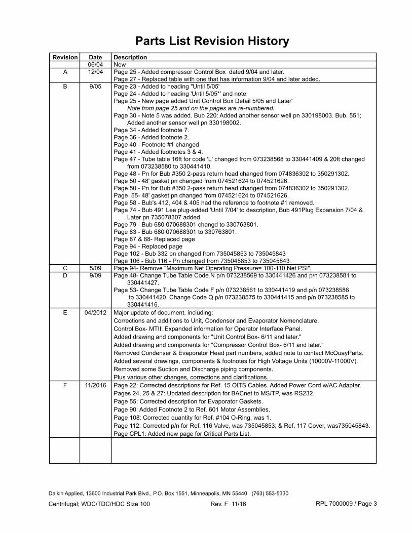
Parts List Revision History Revision Date Description 06/04 New A 12/04 Page 25 - Added compressor Control Box dated 9/04 and later. Page 27 - Replaced table with one that has information 9/04 and later added. B 9/05 Page 23 - Added to heading "Until 5/05' Page 24 - Added to heading 'Until 5/05*' and note Page 25 - New page added Unit Control Box Detail 5/05 and Later' Note from page 25 and on the pages are re-numbered. Page 30 - Note 5 was added. Bub 220: Added another sensor well pn 330198003. Bub. 551; Added another sensor well pn 330198002. Page 34 - Added footnote 7. Page 36 - Added footnote 2. Page 40 - Footnote #1 changed Page 41 - Added footnotes 3 & 4. Page 47 - Tube table 16ft for code 'L' changed from 073238568 to 330441409 & 20ft changed from 073238580 to 330441410. Page 48 - Pn for Bub #350 2-pass return head changed from 074836302 to 350291302. Page 50 - 48' gasket pn changed from 074521624 to 074521626. Page 50 - Pn for Bub #350 2-pass return head changed from 074836302 to 350291302. Page 55- 48' gasket pn changed from 074521624 to 074521626. Page 58 - Bub's 412, 404 & 405 had the reference to footnote #1 removed. Page 74 - Bub 491 Lee plug-added 'Until 7/04' to description, Bub 491Plug Expansion 7/04 & Later pn 735078307 added. Page 79 - Bub 680 070688301 changd to 330763801. Page 83 - Bub 680 070688301 to 330763801. Page 87 & 88- Replaced page Page 94 - Replaced page Page 102 - Bub 332 pn changed from 735045853 to 735045843 Page 106 - Bub 116 - Pn changed from 735045853 to 735045843 C 5/09 Page 94- Remove "Maximum Net Operating Pressure= 100-110 Net PSI". D 9/09 Page 48- Change Tube Table Code N p/n 073238569 to 330441426 and p/n 073238581 to 330441427. Page 53- Change Tube Table Code F p/n 073238561 to 330441419 and p/n 073238586 to 330441420. Change Code Q p/n 073238575 to 330441415 and p/n 073238585 to 330441416. E 04/2012 Major update of document, including: Corrections and additions to Unit, Condenser and Evaporator Nomenclature. Control Box- MTII: Expanded information for Operator Interface Panel. Added drawing and components for "Unit Control Box- 6/11 and later." Added drawing and components for "Compressor Control Box- 6/11 and later." Removed Condenser & Evaporator Head part numbers, added note to contact McQuayParts. Added several drawings, components & footnotes for High Voltage Units (10000V-11000V). Removed some Suction and Discharge piping components. Plus various other changes, corrections and clarifications. F 11/2016 Page 22: Corrected descriptions for Ref. 15 OITS Cables. Added Power Cord w/AC Adapter. Pages 24, 25 & 27: Updated description for BACnet to MS/TP, was RS232. Page 55: Corrected description for Evaporator Gaskets. Page 90: Added Footnote 2 to Ref. 601 Motor Assemblies. Page 108: Corrected quantity for Ref. #104 O-Ring, was 1. Page 112: Corrected p/n for Ref. 116 Valve, was 735045853; & Ref. 117 Cover, was735045843. Page CPL1: Added new page for Critical Parts List.
Daikin Applied, 13600 Industrial Park Blvd., P.O. Box 1551, Minneapolis, MN 55440 (763) 553-5330
RPL 7000009 / Page 4Centrifugal; WDC/TDC/HDC Size 100 Rev. F 11/16
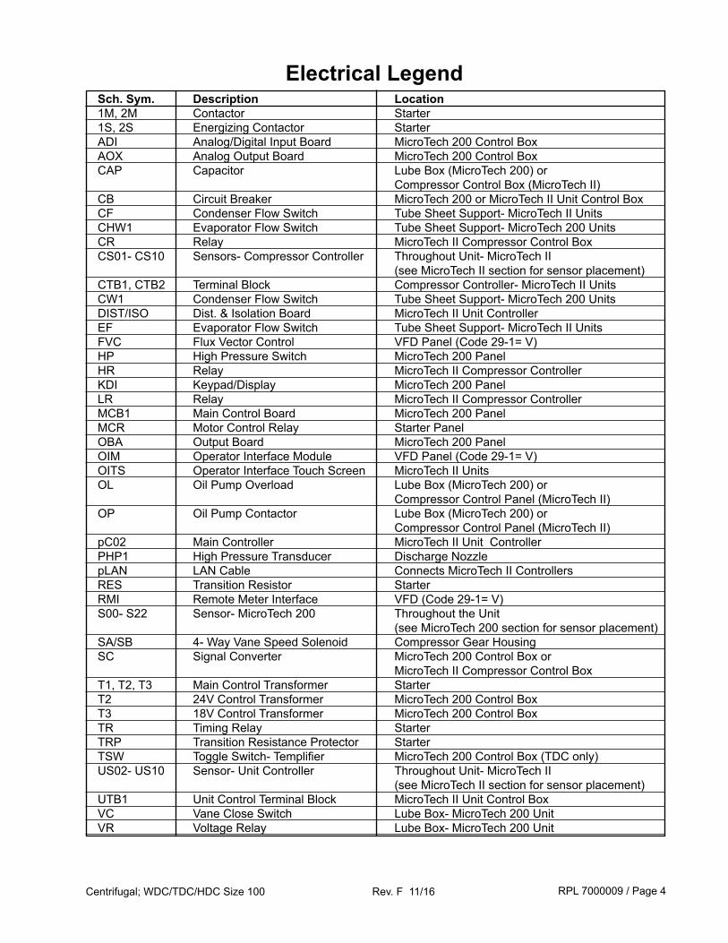
Electrical Legend Sch. Sym. Description Location 1M, 2M Contactor Starter 1S, 2S Energizing Contactor Starter ADI Analog/Digital Input Board MicroTech 200 Control Box AOX Analog Output Board MicroTech 200 Control Box CAP Capacitor Lube Box (MicroTech 200) or Compressor Control Box (MicroTech II) CB Circuit Breaker MicroTech 200 or MicroTech II Unit Control Box CF Condenser Flow Switch Tube Sheet Support- MicroTech II Units CHW1 Evaporator Flow Switch Tube Sheet Support- MicroTech 200 Units CR Relay MicroTech II Compressor Control Box CS01- CS10 Sensors- Compressor Controller Throughout Unit- MicroTech II (see MicroTech II section for sensor placement) CTB1, CTB2 Terminal Block Compressor Controller- MicroTech II Units CW1 Condenser Flow Switch Tube Sheet Support- MicroTech 200 Units DIST/ISO Dist. & Isolation Board MicroTech II Unit Controller EF Evaporator Flow Switch Tube Sheet Support- MicroTech II Units FVC Flux Vector Control VFD Panel (Code 29-1= V) HP High Pressure Switch MicroTech 200 Panel HR Relay MicroTech II Compressor Controller KDI Keypad/Display MicroTech 200 Panel LR Relay MicroTech II Compressor Controller MCB1 Main Control Board MicroTech 200 Panel MCR Motor Control Relay Starter Panel OBA Output Board MicroTech 200 Panel OIM Operator Interface Module VFD Panel (Code 29-1= V) OITS Operator Interface Touch Screen MicroTech II Units OL Oil Pump Overload Lube Box (MicroTech 200) or Compressor Control Panel (MicroTech II) OP Oil Pump Contactor Lube Box (MicroTech 200) or Compressor Control Panel (MicroTech II) pC02 Main Controller MicroTech II Unit Controller PHP1 High Pressure Transducer Discharge Nozzle pLAN LAN Cable Connects MicroTech II Controllers RES Transition Resistor Starter RMI Remote Meter Interface VFD (Code 29-1= V) S00- S22 Sensor- MicroTech 200 Throughout the Unit (see MicroTech 200 section for sensor placement) SA/SB 4- Way Vane Speed Solenoid Compressor Gear Housing SC Signal Converter MicroTech 200 Control Box or MicroTech II Compressor Control Box T1, T2, T3 Main Control Transformer Starter T2 24V Control Transformer MicroTech 200 Control Box T3 18V Control Transformer MicroTech 200 Control Box TR Timing Relay Starter TRP Transition Resistance Protector Starter TSW Toggle Switch- Templifier MicroTech 200 Control Box (TDC only) US02- US10 Sensor- Unit Controller Throughout Unit- MicroTech II (see MicroTech II section for sensor placement) UTB1 Unit Control Terminal Block MicroTech II Unit Control Box VC Vane Close Switch Lube Box- MicroTech 200 Unit VR Voltage Relay Lube Box- MicroTech 200 Unit
RPL 7000009 / Page 5Centrifugal; WDC/TDC/HDC Size 100 Rev. F 11/16
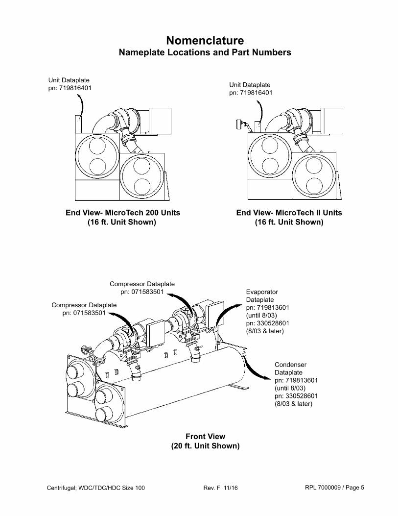
NomenclatureNameplate Locations and Part Numbers
Compressor Dataplate pn: 071583501 Evaporator
Dataplate pn: 719813601 (until 8/03)pn: 330528601(8/03 & later)
Unit Dataplate pn: 719816401
Front View(20 ft. Unit Shown)
End View- MicroTech 200 Units(16 ft. Unit Shown)
End View- MicroTech II Units(16 ft. Unit Shown)
Condenser Dataplate pn: 719813601 (until 8/03)pn: 330528601(8/03 & later)
Unit Dataplate pn: 719816401
Compressor Dataplate pn: 071583501
RPL 7000009 / Page 6Centrifugal; WDC/TDC/HDC Size 100 Rev. F 11/16
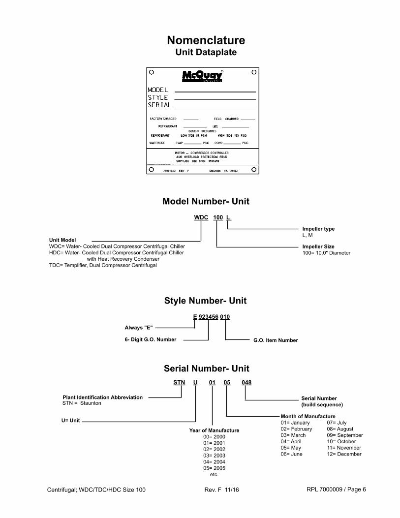
STN U 01 05 048
Plant Identification AbbreviationSTN = Staunton
Serial Number (build sequence)
U= Unit
Year of Manufacture00= 200001= 200102= 200203= 200304= 200405= 2005
etc.
Month of Manufacture01= January02= February03= March04= April05= May06= June
07= July08= August09= September10= October11= November12= December
Serial Number- Unit
NomenclatureUnit Dataplate
WDC 100 L
Unit ModelWDC= Water- Cooled Dual Compressor Centrifugal ChillerHDC= Water- Cooled Dual Compressor Centrifugal Chiller with Heat Recovery CondenserTDC= Templifier, Dual Compressor Centrifugal
Impeller Size100= 10.0" Diameter
Impeller typeL, M
Model Number- Unit
E 923456 010
6- Digit G.O. Number G.O. Item Number
Style Number- Unit
Always "E"
RPL 7000009 / Page 7Centrifugal; WDC/TDC/HDC Size 100 Rev. F 11/16
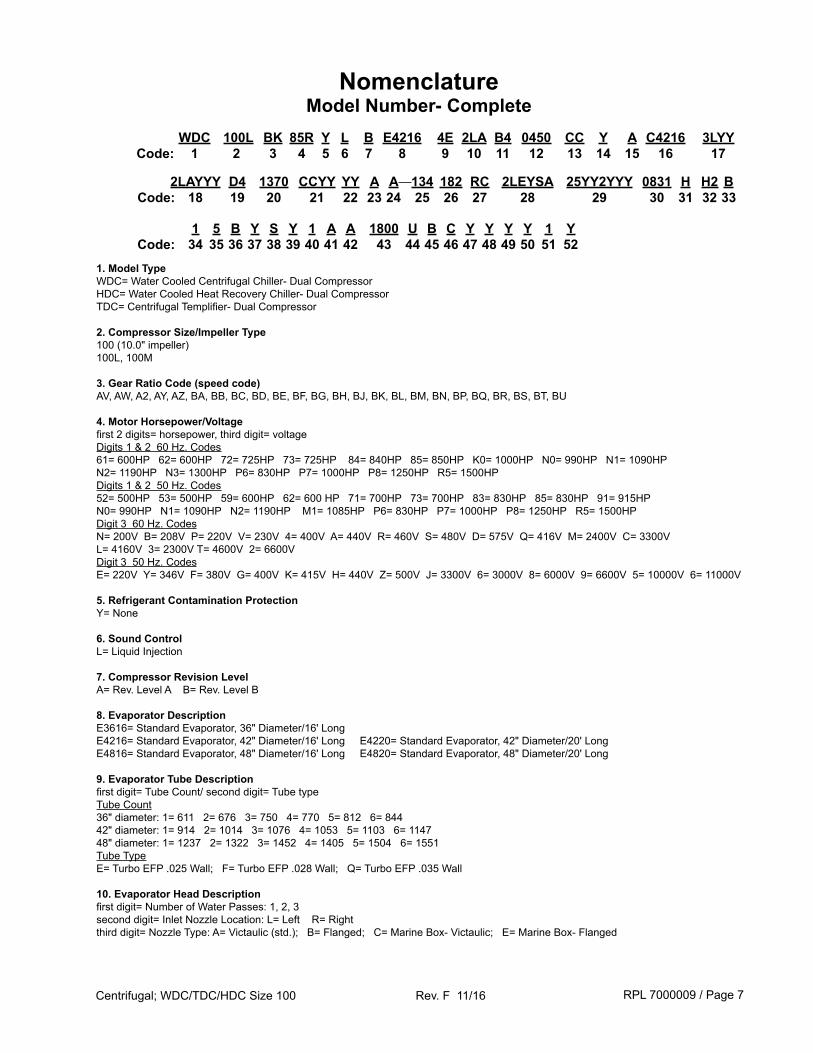
1. Model TypeWDC= Water Cooled Centrifugal Chiller- Dual CompressorHDC= Water Cooled Heat Recovery Chiller- Dual CompressorTDC= Centrifugal Templifier- Dual Compressor
2. Compressor Size/Impeller Type100 (10.0" impeller)100L, 100M
3. Gear Ratio Code (speed code)AV, AW, A2, AY, AZ, BA, BB, BC, BD, BE, BF, BG, BH, BJ, BK, BL, BM, BN, BP, BQ, BR, BS, BT, BU
4. Motor Horsepower/Voltagefirst 2 digits= horsepower, third digit= voltageDigits 1 & 2 60 Hz. Codes61= 600HP 62= 600HP 72= 725HP 73= 725HP 84= 840HP 85= 850HP K0= 1000HP N0= 990HP N1= 1090HP N2= 1190HP N3= 1300HP P6= 830HP P7= 1000HP P8= 1250HP R5= 1500HP Digits 1 & 2 50 Hz. Codes52= 500HP 53= 500HP 59= 600HP 62= 600 HP 71= 700HP 73= 700HP 83= 830HP 85= 830HP 91= 915HP N0= 990HP N1= 1090HP N2= 1190HP M1= 1085HP P6= 830HP P7= 1000HP P8= 1250HP R5= 1500HP Digit 3 60 Hz. CodesN= 200V B= 208V P= 220V V= 230V 4= 400V A= 440V R= 460V S= 480V D= 575V Q= 416V M= 2400V C= 3300V L= 4160V 3= 2300V T= 4600V 2= 6600VDigit 3 50 Hz. CodesE= 220V Y= 346V F= 380V G= 400V K= 415V H= 440V Z= 500V J= 3300V 6= 3000V 8= 6000V 9= 6600V 5= 10000V 6= 11000V
5. Refrigerant Contamination ProtectionY= None
6. Sound ControlL= Liquid Injection
7. Compressor Revision LevelA= Rev. Level A B= Rev. Level B
8. Evaporator DescriptionE3616= Standard Evaporator, 36" Diameter/16' Long E4216= Standard Evaporator, 42" Diameter/16' Long E4220= Standard Evaporator, 42" Diameter/20' Long E4816= Standard Evaporator, 48" Diameter/16' Long E4820= Standard Evaporator, 48" Diameter/20' Long
9. Evaporator Tube Descriptionfirst digit= Tube Count/ second digit= Tube typeTube Count36" diameter: 1= 611 2= 676 3= 750 4= 770 5= 812 6= 84442" diameter: 1= 914 2= 1014 3= 1076 4= 1053 5= 1103 6= 114748" diameter: 1= 1237 2= 1322 3= 1452 4= 1405 5= 1504 6= 1551Tube TypeE= Turbo EFP .025 Wall; F= Turbo EFP .028 Wall; Q= Turbo EFP .035 Wall
10. Evaporator Head Descriptionfirst digit= Number of Water Passes: 1, 2, 3second digit= Inlet Nozzle Location: L= Left R= Rightthird digit= Nozzle Type: A= Victaulic (std.); B= Flanged; C= Marine Box- Victaulic; E= Marine Box- Flanged
WDC 100L BK 85R Y L B E4216 4E 2LA B4 0450 CC Y A C4216 3LYY Code: 1 2 3 4 5 6 7 8 9 10 11 12 13 14 15 16 17
NomenclatureModel Number- Complete
2LAYYY D4 1370 CCYY YY A A 134 182 RC 2LEYSA 25YY2YYY 0831 H H2 B Code: 18 19 20 21 22 23 24 25 26 27 28 29 30 31 32 33
1 5 B Y S Y 1 A A 1800 U B C Y Y Y Y 1 Y Code: 34 35 36 37 38 39 40 41 42 43 44 45 46 47 48 49 50 51 52
RPL 7000009 / Page 8Centrifugal; WDC/TDC/HDC Size 100 Rev. F 11/16
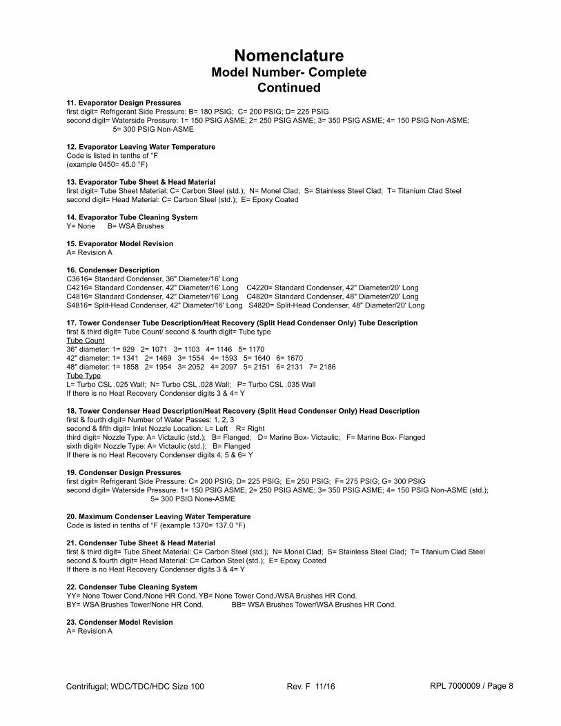
11. Evaporator Design Pressuresfirst digit= Refrigerant Side Pressure: B= 180 PSIG; C= 200 PSIG; D= 225 PSIGsecond digit= Waterside Pressure: 1= 150 PSIG ASME; 2= 250 PSIG ASME; 3= 350 PSIG ASME; 4= 150 PSIG Non-ASME; 5= 300 PSIG Non-ASME
12. Evaporator Leaving Water TemperatureCode is listed in tenths of °F(example 0450= 45.0 °F)
13. Evaporator Tube Sheet & Head Materialfirst digit= Tube Sheet Material: C= Carbon Steel (std.); N= Monel Clad; S= Stainless Steel Clad; T= Titanium Clad Steelsecond digit= Head Material: C= Carbon Steel (std.); E= Epoxy Coated
14. Evaporator Tube Cleaning SystemY= None B= WSA Brushes
15. Evaporator Model RevisionA= Revision A
16. Condenser DescriptionC3616= Standard Condenser, 36" Diameter/16' LongC4216= Standard Condenser, 42" Diameter/16' Long C4220= Standard Condenser, 42" Diameter/20' LongC4816= Standard Condenser, 42" Diameter/16' Long C4820= Standard Condenser, 48" Diameter/20' LongS4816= Split-Head Condenser, 42" Diameter/16' Long S4820= Split-Head Condenser, 48" Diameter/20' Long
17. Tower Condenser Tube Description/Heat Recovery (Split Head Condenser Only) Tube Descriptionfirst & third digit= Tube Count/ second & fourth digit= Tube typeTube Count36" diameter: 1= 929 2= 1071 3= 1103 4= 1146 5= 117042" diameter: 1= 1341 2= 1469 3= 1554 4= 1593 5= 1640 6= 167048" diameter: 1= 1858 2= 1954 3= 2052 4= 2097 5= 2151 6= 2131 7= 2186Tube TypeL= Turbo CSL .025 Wall; N= Turbo CSL .028 Wall; P= Turbo CSL .035 WallIf there is no Heat Recovery Condenser digits 3 & 4= Y
18. Tower Condenser Head Description/Heat Recovery (Split Head Condenser Only) Head Descriptionfirst & fourth digit= Number of Water Passes: 1, 2, 3second & fifth digit= Inlet Nozzle Location: L= Left R= Rightthird digit= Nozzle Type: A= Victaulic (std.); B= Flanged; D= Marine Box- Victaulic; F= Marine Box- Flangedsixth digit= Nozzle Type: A= Victaulic (std.); B= FlangedIf there is no Heat Recovery Condenser digits 4, 5 & 6= Y
19. Condenser Design Pressuresfirst digit= Refrigerant Side Pressure: C= 200 PSIG; D= 225 PSIG; E= 250 PSIG; F= 275 PSIG; G= 300 PSIGsecond digit= Waterside Pressure: 1= 150 PSIG ASME; 2= 250 PSIG ASME; 3= 350 PSIG ASME; 4= 150 PSIG Non-ASME (std.); 5= 300 PSIG None-ASME
20. Maximum Condenser Leaving Water TemperatureCode is listed in tenths of °F (example 1370= 137.0 °F)
21. Condenser Tube Sheet & Head Materialfirst & third digit= Tube Sheet Material: C= Carbon Steel (std.); N= Monel Clad; S= Stainless Steel Clad; T= Titanium Clad Steelsecond & fourth digit= Head Material: C= Carbon Steel (std.); E= Epoxy CoatedIf there is no Heat Recovery Condenser digits 3 & 4= Y
22. Condenser Tube Cleaning SystemYY= None Tower Cond./None HR Cond. YB= None Tower Cond./WSA Brushes HR Cond.BY= WSA Brushes Tower/None HR Cond. BB= WSA Brushes Tower/WSA Brushes HR Cond.
23. Condenser Model RevisionA= Revision A
NomenclatureModel Number- Complete
Continued
RPL 7000009 / Page 9Centrifugal; WDC/TDC/HDC Size 100 Rev. F 11/16
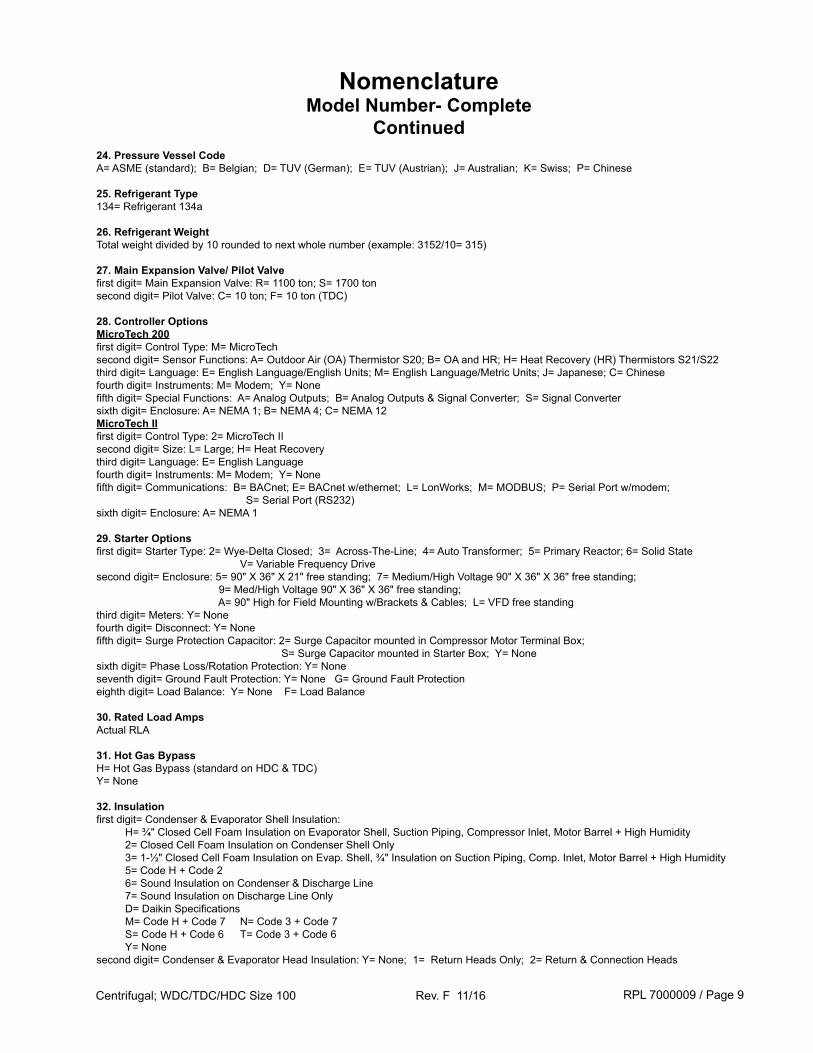
24. Pressure Vessel CodeA= ASME (standard); B= Belgian; D= TUV (German); E= TUV (Austrian); J= Australian; K= Swiss; P= Chinese
25. Refrigerant Type134= Refrigerant 134a
26. Refrigerant WeightTotal weight divided by 10 rounded to next whole number (example: 3152/10= 315)
27. Main Expansion Valve/ Pilot Valvefirst digit= Main Expansion Valve: R= 1100 ton; S= 1700 tonsecond digit= Pilot Valve: C= 10 ton; F= 10 ton (TDC)
28. Controller OptionsMicroTech 200first digit= Control Type: M= MicroTechsecond digit= Sensor Functions: A= Outdoor Air (OA) Thermistor S20; B= OA and HR; H= Heat Recovery (HR) Thermistors S21/S22third digit= Language: E= English Language/English Units; M= English Language/Metric Units; J= Japanese; C= Chinesefourth digit= Instruments: M= Modem; Y= Nonefifth digit= Special Functions: A= Analog Outputs; B= Analog Outputs & Signal Converter; S= Signal Convertersixth digit= Enclosure: A= NEMA 1; B= NEMA 4; C= NEMA 12MicroTech IIfirst digit= Control Type: 2= MicroTech IIsecond digit= Size: L= Large; H= Heat Recoverythird digit= Language: E= English Languagefourth digit= Instruments: M= Modem; Y= Nonefifth digit= Communications: B= BACnet; E= BACnet w/ethernet; L= LonWorks; M= MODBUS; P= Serial Port w/modem; S= Serial Port (RS232)sixth digit= Enclosure: A= NEMA 1
29. Starter Optionsfirst digit= Starter Type: 2= Wye-Delta Closed; 3= Across-The-Line; 4= Auto Transformer; 5= Primary Reactor; 6= Solid State V= Variable Frequency Drivesecond digit= Enclosure: 5= 90" X 36" X 21" free standing; 7= Medium/High Voltage 90" X 36" X 36" free standing; 9= Med/High Voltage 90" X 36" X 36" free standing; A= 90" High for Field Mounting w/Brackets & Cables; L= VFD free standingthird digit= Meters: Y= Nonefourth digit= Disconnect: Y= Nonefifth digit= Surge Protection Capacitor: 2= Surge Capacitor mounted in Compressor Motor Terminal Box; S= Surge Capacitor mounted in Starter Box; Y= Nonesixth digit= Phase Loss/Rotation Protection: Y= Noneseventh digit= Ground Fault Protection: Y= None G= Ground Fault Protectioneighth digit= Load Balance: Y= None F= Load Balance
30. Rated Load AmpsActual RLA
31. Hot Gas BypassH= Hot Gas Bypass (standard on HDC & TDC)Y= None
32. Insulationfirst digit= Condenser & Evaporator Shell Insulation: H= ¾" Closed Cell Foam Insulation on Evaporator Shell, Suction Piping, Compressor Inlet, Motor Barrel + High Humidity 2= Closed Cell Foam Insulation on Condenser Shell Only 3= 1-½" Closed Cell Foam Insulation on Evap. Shell, ¾" Insulation on Suction Piping, Comp. Inlet, Motor Barrel + High Humidity 5= Code H + Code 2 6= Sound Insulation on Condenser & Discharge Line 7= Sound Insulation on Discharge Line Only D= Daikin Specifications M= Code H + Code 7 N= Code 3 + Code 7 S= Code H + Code 6 T= Code 3 + Code 6 Y= Nonesecond digit= Condenser & Evaporator Head Insulation: Y= None; 1= Return Heads Only; 2= Return & Connection Heads
NomenclatureModel Number- Complete
Continued
RPL 7000009 / Page 10Centrifugal; WDC/TDC/HDC Size 100 Rev. F 11/16
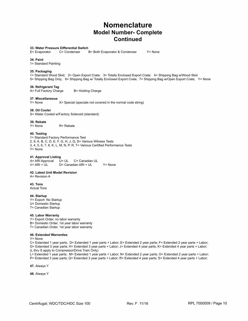
33. Water Pressure Differential SwitchE= Evaporator C= Condenser B= Both Evaporator & Condenser Y= None
34. Paint1= Standard Painting
35. Packaging1= Standard Wood Skid; 2= Open Export Crate; 3= Totally Enclosed Export Crate; 4= Shipping Bag w/Wood Skid5= Shipping Bag Only; 6= Shipping Bag w/ Totally Enclosed Export Crate; 7= Shipping Bag w/Open Export Crate; Y= None
36. Refrigerant TagA= Full Factory Charge B= Holding Charge
37. MiscellaneousY= None X= Special (specials not covered in the normal code string)
38. Oil CoolerS= Water Cooled w/Factory Solenoid (standard)
39. RebateY= None R= Rebate
40. Testing1= Standard Factory Performance Test2, 9, A, B, C, D, E, F, G, H, J, Q, S= Various Witness Tests3, 4, 5, 6, 7, 8, K, L, M, N, P, R, T= Various Certified Performance TestsY= None
41. Approval ListingA= ARI Approval U= UL C= Canadian ULV= ARI + UL D= Canadian ARI + UL Y= None
42. Latest Unit Model RevisionA= Revision A
43. TonsActual Tons
44. StartupY= Export- No StartupU= Domestic Startup7= Canadian Startup
45. Labor WarrantyY= Export Order, no labor warrantyB= Domestic Order, 1st year labor warranty7= Canadian Order, 1st year labor warranty
46. Extended WarrantiesY= NoneC= Extended 1 year parts; D= Extended 1 year parts + Labor; E= Extended 2 year parts; F= Extended 2 year parts + Labor;G= Extended 3 year parts; H= Extended 3 year parts + Labor; J= Extended 4 year parts; K= Extended 4 year parts + Labor;(L thru S apply to Compressor/Drive Train Only)L= Extended 1 year parts; M= Extended 1 year parts + Labor; N= Extended 2 year parts; O= Extended 2 year parts + Labor;P= Extended 3 year parts; Q= Extended 3 year parts + Labor; R= Extended 4 year parts; S= Extended 4 year parts + Labor;
47. Always Y
48. Always Y
NomenclatureModel Number- Complete
Continued
RPL 7000009 / Page 11Centrifugal; WDC/TDC/HDC Size 100 Rev. F 11/16
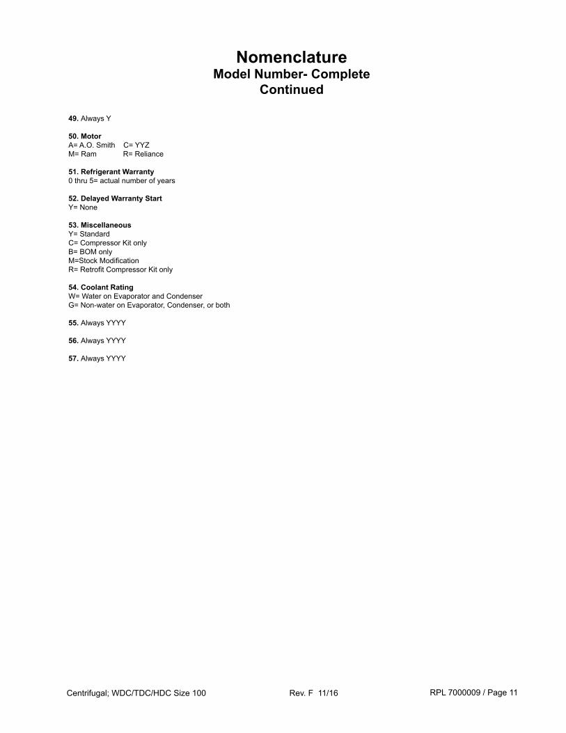
49. Always Y
50. MotorA= A.O. Smith C= YYZM= Ram R= Reliance
51. Refrigerant Warranty0 thru 5= actual number of years
52. Delayed Warranty StartY= None
53. MiscellaneousY= StandardC= Compressor Kit onlyB= BOM onlyM=Stock ModificationR= Retrofit Compressor Kit only
54. Coolant RatingW= Water on Evaporator and CondenserG= Non-water on Evaporator, Condenser, or both
55. Always YYYY
56. Always YYYY
57. Always YYYY
NomenclatureModel Number- Complete
Continued
RPL 7000009 / Page 12Centrifugal; WDC/TDC/HDC Size 100 Rev. F 11/16
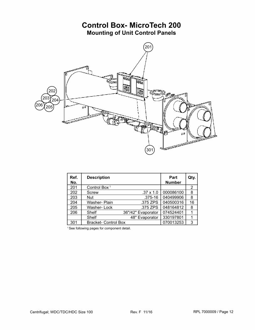
Control Box- MicroTech 200Mounting of Unit Control Panels
Ref. Description Part Qty. No. Number 201 Control Box 1 2 202 Screw .37 x 1.0 000086100 8 203 Nut .375-16 040499906 8 204 Washer- Plain .375 ZPS 040500316 16 205 Washer- Lock .375 ZPS 048164812 8 206 Shelf 36"/42" Evaporator 074524401 1 Shelf 48" Evaporator 330197801 1 301 Bracket- Control Box 070013253 31 See following pages for component detail.
201
301
202
203 204206 205
RPL 7000009 / Page 13Centrifugal; WDC/TDC/HDC Size 100 Rev. F 11/16
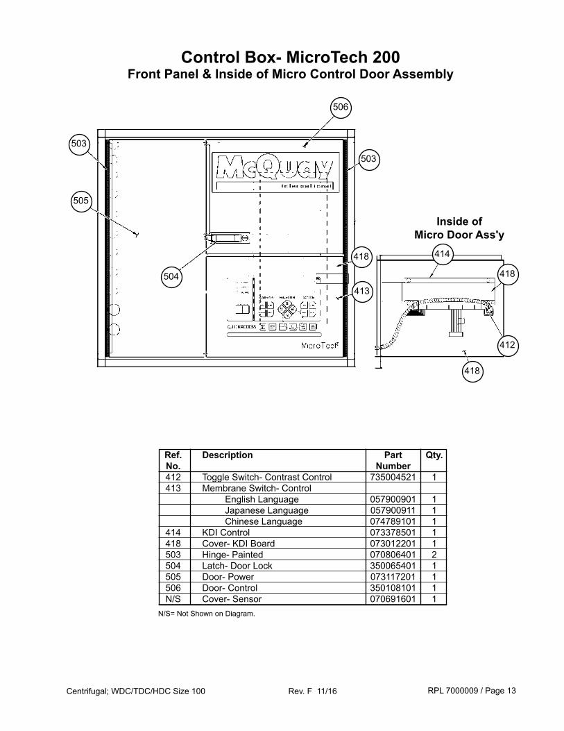
Control Box- MicroTech 200Front Panel & Inside of Micro Control Door Assembly
503
505
504
506
503
418
413
Ref. Description Part Qty. No. Number 412 Toggle Switch- Contrast Control 735004521 1 413 Membrane Switch- Control English Language 057900901 1 Japanese Language 057900911 1 Chinese Language 074789101 1 414 KDI Control 073378501 1 418 Cover- KDI Board 073012201 1 503 Hinge- Painted 070806401 2 504 Latch- Door Lock 350065401 1 505 Door- Power 073117201 1 506 Door- Control 350108101 1 N/S Cover- Sensor 070691601 1N/S= Not Shown on Diagram.
Inside of Micro Door Ass'y
414
418
412
418
RPL 7000009 / Page 14Centrifugal; WDC/TDC/HDC Size 100 Rev. F 11/16
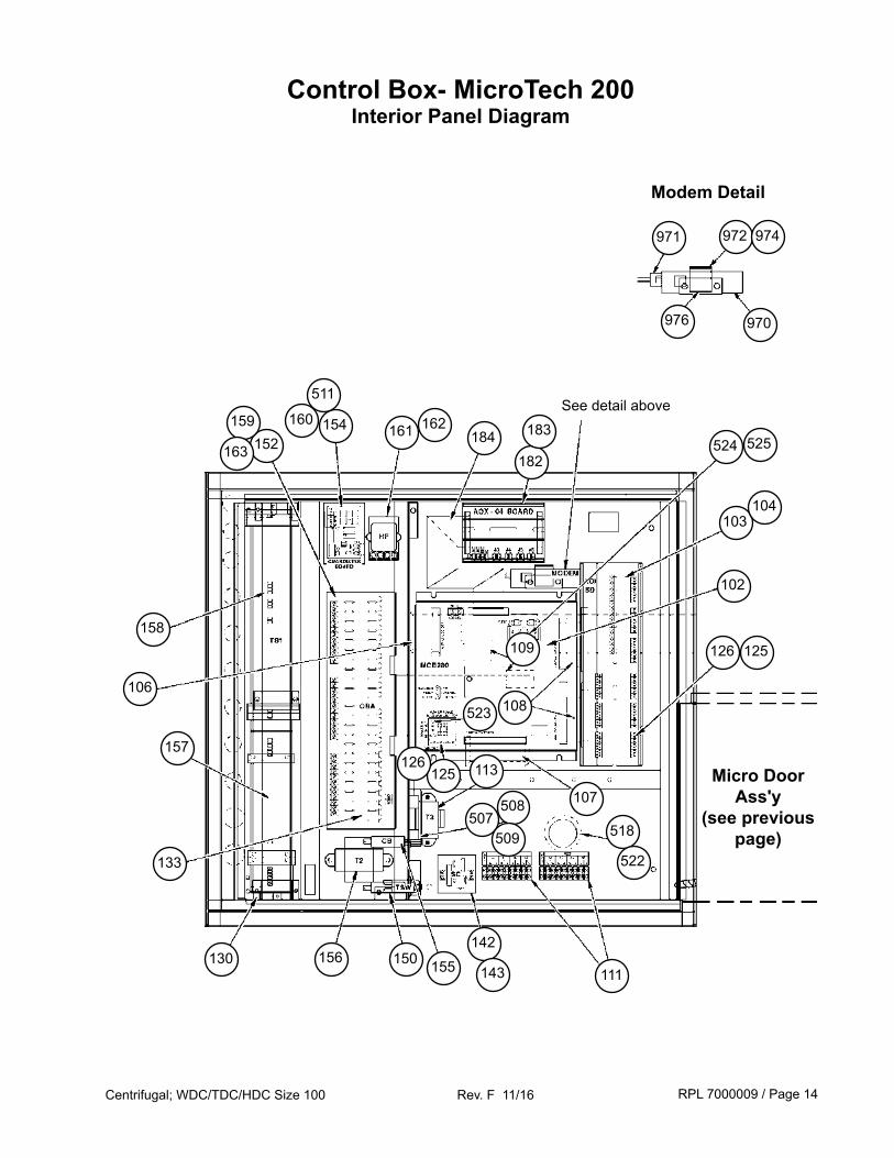
Control Box- MicroTech 200Interior Panel Diagram
161 162
507508
509 518
Micro Door Ass'y
(see previous page)
111
142
154160
152159
163
158
133
130 156 150 155
113125126
107
157
125126
108
109
102
103104
524 525184182
183
Modem Detail
971 972 974
970976
523
143
106
522
511See detail above
RPL 7000009 / Page 15Centrifugal; WDC/TDC/HDC Size 100 Rev. F 11/16
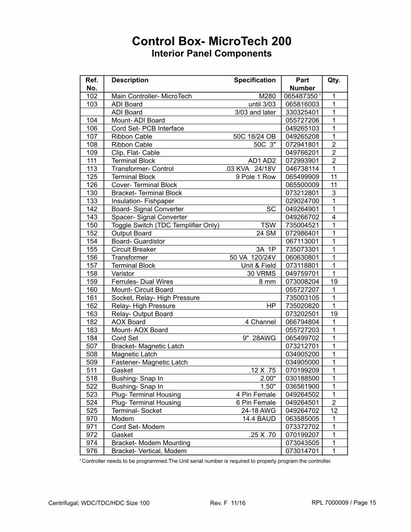
Control Box- MicroTech 200Interior Panel Components
Ref. Description Specification Part Qty. No. Number 102 Main Controller- MicroTech M280 065487350 1 1 103 ADI Board until 3/03 065816003 1 ADI Board 3/03 and later 330325401 1 104 Mount- ADI Board 055727206 1 106 Cord Set- PCB Interface 049265103 1 107 Ribbon Cable 50C 18/24 OB 049265208 1 108 Ribbon Cable 50C 3" 072941801 2 109 Clip, Flat- Cable 049766201 2 111 Terminal Block AD1 AD2 072993901 2 113 Transformer- Control .03 KVA 24/18V 046738114 1 125 Terminal Block 9 Pole 1 Row 065499909 11 126 Cover- Terminal Block 065500009 11 130 Bracket- Terminal Block 073212801 3 133 Insulation- Fishpaper 029024700 1 142 Board- Signal Converter SC 049264901 1 143 Spacer- Signal Converter 049266702 4 150 Toggle Switch (TDC Templifier Only) TSW 735004521 1 152 Output Board 24 SM 072986401 1 154 Board- Guardistor 067113001 1 155 Circuit Breaker 3A 1P 735073301 1 156 Transformer 50 VA 120/24V 060630801 1 157 Terminal Block Unit & Field 073118801 1 158 Varistor 30 VRMS 049759701 1 159 Ferrules- Dual Wires 8 mm 073008204 19 160 Mount- Circuit Board 055727207 1 161 Socket, Relay- High Pressure 735003105 1 162 Relay- High Pressure HP 735020820 1 163 Relay- Output Board 073202501 19 182 AOX Board 4 Channel 066794804 1 183 Mount- AOX Board 055727203 1 184 Cord Set 9" 28AWG 065499702 1 507 Bracket- Magnetic Latch 073212701 1 508 Magnetic Latch 034905200 1 509 Fastener- Magnetic Latch 034905000 1 511 Gasket .12 X .75 070199209 1 518 Bushing- Snap In 2.00" 030188500 1 522 Bushing- Snap In 1.50" 036561900 1 523 Plug- Terminal Housing 4 Pin Female 049264502 1 524 Plug- Terminal Housing 6 Pin Female 049264501 2 525 Terminal- Socket 24-18 AWG 049264702 12 970 Modem 14.4 BAUD 063585005 1 971 Cord Set- Modem 073372702 1 972 Gasket .25 X .70 070199207 1 974 Bracket- Modem Mounting 073043505 1 976 Bracket- Vertical, Modem 073014701 11 Controller needs to be programmed.The Unit serial number is required to properly program the controller.
RPL 7000009 / Page 16Centrifugal; WDC/TDC/HDC Size 100 Rev. F 11/16
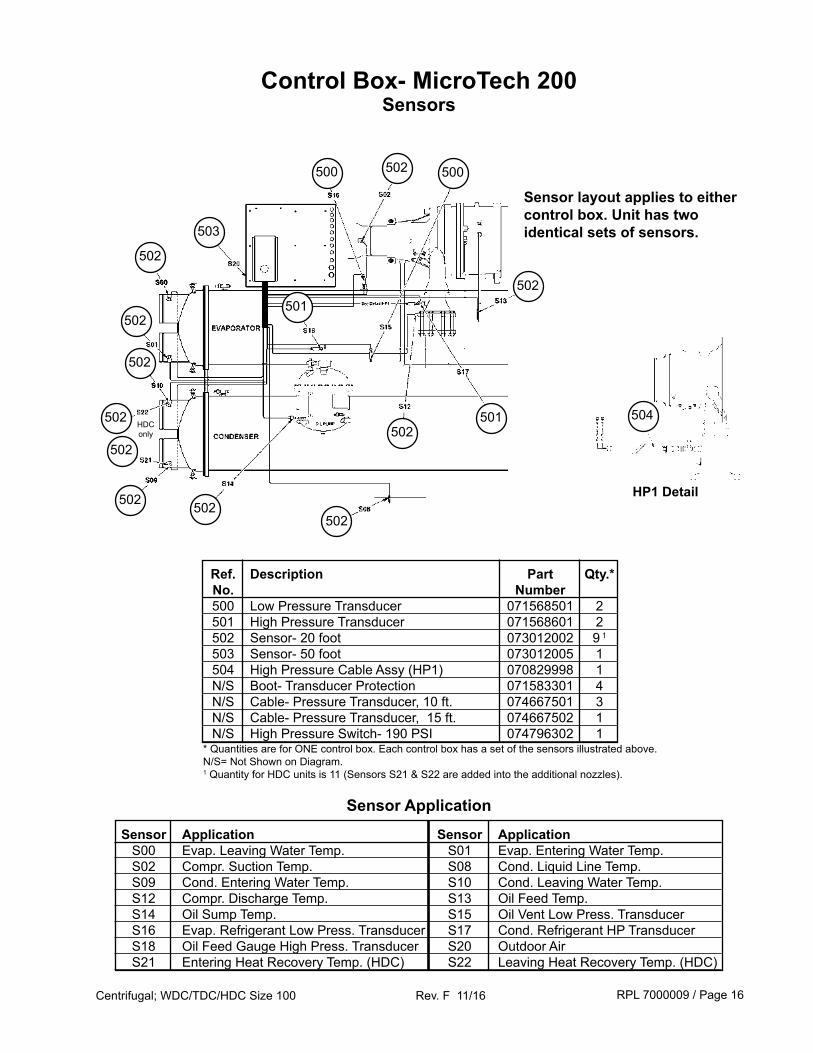
Control Box- MicroTech 200Sensors
502
503
500
501
Ref. Description Part Qty.* No. Number 500 Low Pressure Transducer 071568501 2 501 High Pressure Transducer 071568601 2 502 Sensor- 20 foot 073012002 9 1
503 Sensor- 50 foot 073012005 1 504 High Pressure Cable Assy (HP1) 070829998 1 N/S Boot- Transducer Protection 071583301 4 N/S Cable- Pressure Transducer, 10 ft. 074667501 3 N/S Cable- Pressure Transducer, 15 ft. 074667502 1 N/S High Pressure Switch- 190 PSI 074796302 1* Quantities are for ONE control box. Each control box has a set of the sensors illustrated above.N/S= Not Shown on Diagram.1 Quantity for HDC units is 11 (Sensors S21 & S22 are added into the additional nozzles).
Sensor Application Sensor Application S00 Evap. Leaving Water Temp. S01 Evap. Entering Water Temp. S02 Compr. Suction Temp. S08 Cond. Liquid Line Temp. S09 Cond. Entering Water Temp. S10 Cond. Leaving Water Temp. S12 Compr. Discharge Temp. S13 Oil Feed Temp. S14 Oil Sump Temp. S15 Oil Vent Low Press. Transducer S16 Evap. Refrigerant Low Press. Transducer S17 Cond. Refrigerant HP Transducer S18 Oil Feed Gauge High Press. Transducer S20 Outdoor Air S21 Entering Heat Recovery Temp. (HDC) S22 Leaving Heat Recovery Temp. (HDC)
Sensor Application
HP1 Detail
501
502
502
502
502
502
502
502
502
502
502
500
504HDC only
Sensor layout applies to either control box. Unit has two identical sets of sensors.
RPL 7000009 / Page 17Centrifugal; WDC/TDC/HDC Size 100 Rev. F 11/16
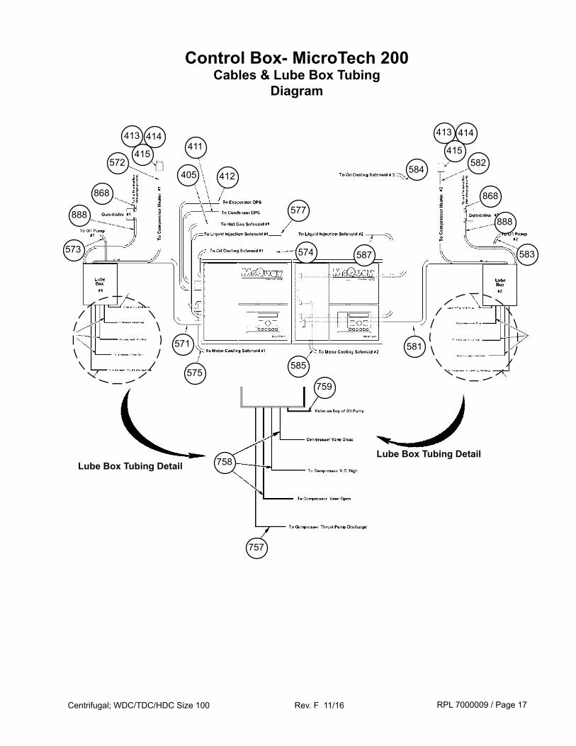
Control Box- MicroTech 200Cables & Lube Box Tubing
Diagram
Lube Box Tubing Detail
888
411
412
575
868
573
758
405
571
413 414
415572
Lube Box Tubing Detail
759
757
585
577
574
584
587
582
888
868
413 414
415
583
581
RPL 7000009 / Page 18Centrifugal; WDC/TDC/HDC Size 100 Rev. F 11/16
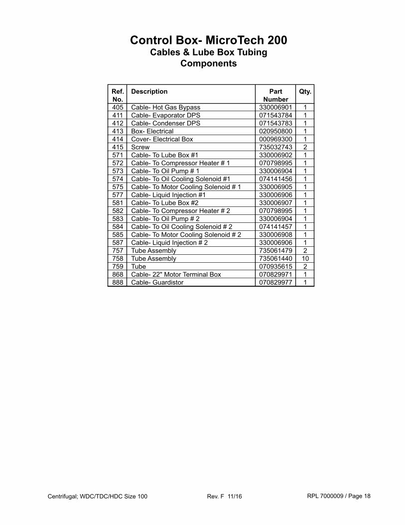
Ref. Description Part Qty. No. Number 405 Cable- Hot Gas Bypass 330006901 1 411 Cable- Evaporator DPS 071543784 1 412 Cable- Condenser DPS 071543783 1 413 Box- Electrical 020950800 1 414 Cover- Electrical Box 000969300 1 415 Screw 735032743 2 571 Cable- To Lube Box #1 330006902 1 572 Cable- To Compressor Heater # 1 070798995 1 573 Cable- To Oil Pump # 1 330006904 1 574 Cable- To Oil Cooling Solenoid #1 074141456 1 575 Cable- To Motor Cooling Solenoid # 1 330006905 1 577 Cable- Liquid Injection #1 330006906 1 581 Cable- To Lube Box #2 330006907 1 582 Cable- To Compressor Heater # 2 070798995 1 583 Cable- To Oil Pump # 2 330006904 1 584 Cable- To Oil Cooling Solenoid # 2 074141457 1 585 Cable- To Motor Cooling Solenoid # 2 330006908 1 587 Cable- Liquid Injection # 2 330006906 1 757 Tube Assembly 735061479 2 758 Tube Assembly 735061440 10 759 Tube 070935615 2 868 Cable- 22" Motor Terminal Box 070829971 1 888 Cable- Guardistor 070829977 1
Control Box- MicroTech 200Cables & Lube Box Tubing
Components
RPL 7000009 / Page 19Centrifugal; WDC/TDC/HDC Size 100 Rev. F 11/16
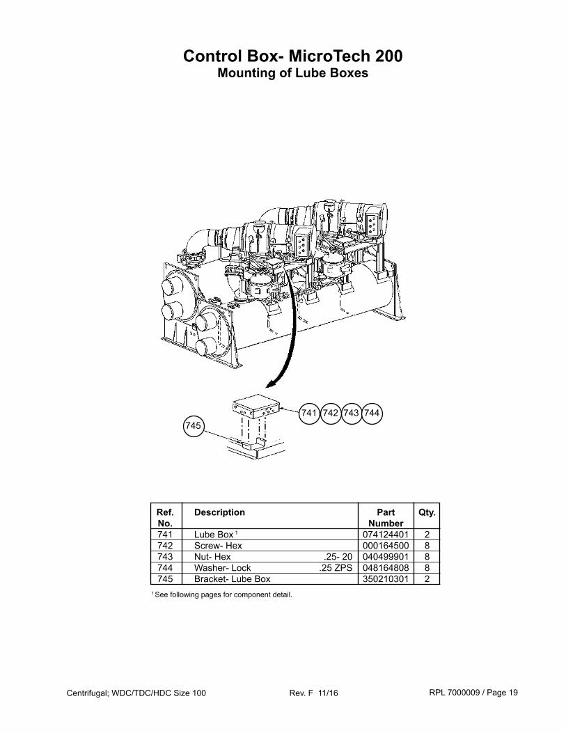
Control Box- MicroTech 200Mounting of Lube Boxes
Ref. Description Part Qty. No. Number 741 Lube Box 1 074124401 2 742 Screw- Hex 000164500 8 743 Nut- Hex .25- 20 040499901 8 744 Washer- Lock .25 ZPS 048164808 8 745 Bracket- Lube Box 350210301 21 See following pages for component detail.
741 742 743 744745
RPL 7000009 / Page 20Centrifugal; WDC/TDC/HDC Size 100 Rev. F 11/16
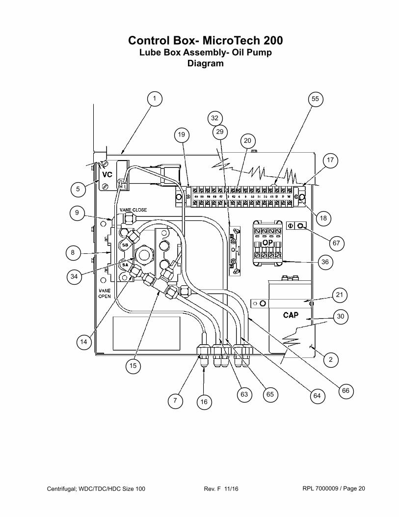
Control Box- MicroTech 200Lube Box Assembly- Oil Pump
Diagram
19
1
29
32
20
55
17
18
67
5
9
8
34
36
14
15
7 1663 65 64
66
2
30
21
RPL 7000009 / Page 21Centrifugal; WDC/TDC/HDC Size 100 Rev. F 11/16
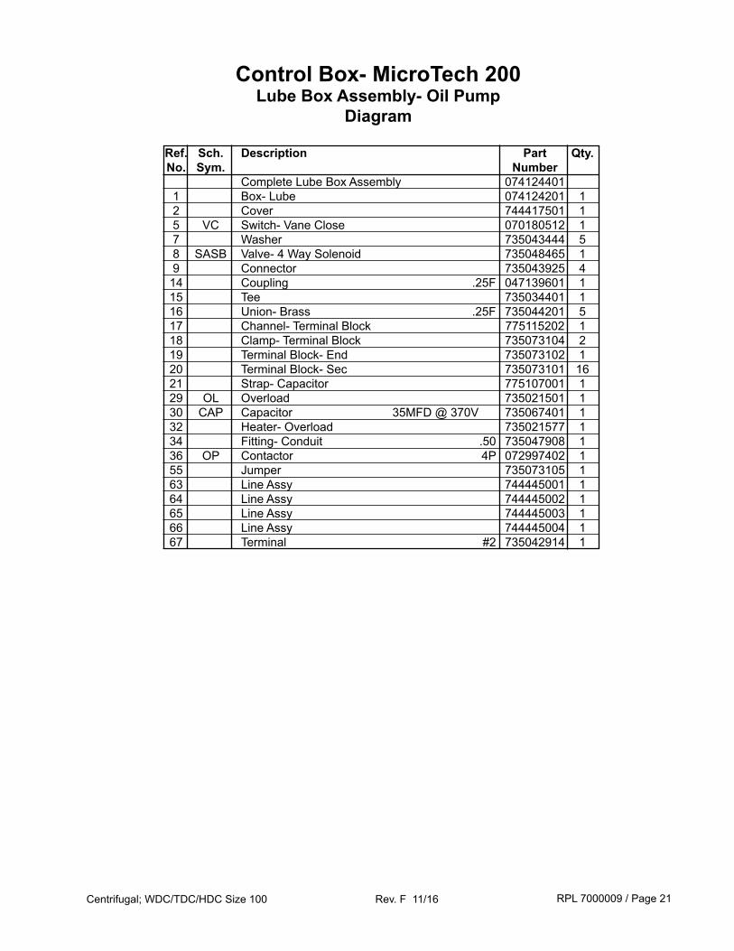
Ref. Sch. Description Part Qty. No. Sym. Number Complete Lube Box Assembly 074124401 1 Box- Lube 074124201 1 2 Cover 744417501 1 5 VC Switch- Vane Close 070180512 1 7 Washer 735043444 5 8 SASB Valve- 4 Way Solenoid 735048465 1 9 Connector 735043925 4 14 Coupling .25F 047139601 1 15 Tee 735034401 1 16 Union- Brass .25F 735044201 5 17 Channel- Terminal Block 775115202 1 18 Clamp- Terminal Block 735073104 2 19 Terminal Block- End 735073102 1 20 Terminal Block- Sec 735073101 16 21 Strap- Capacitor 775107001 1 29 OL Overload 735021501 1 30 CAP Capacitor 35MFD @ 370V 735067401 1 32 Heater- Overload 735021577 1 34 Fitting- Conduit .50 735047908 1 36 OP Contactor 4P 072997402 1 55 Jumper 735073105 1 63 Line Assy 744445001 1 64 Line Assy 744445002 1 65 Line Assy 744445003 1 66 Line Assy 744445004 1 67 Terminal #2 735042914 1
Control Box- MicroTech 200Lube Box Assembly- Oil Pump
Diagram
RPL 7000009 / Page 22Centrifugal; WDC/TDC/HDC Size 100 Rev. F 11/16
Control Box- MicroTech IIUnit Control Box Mounting Components
24
19
22
2321
18 27
22
24
22
23
26
15
19
18
16
25
NOTE: Original design Operator Interface Panel shown. Mounting hardware is the same for all panels.
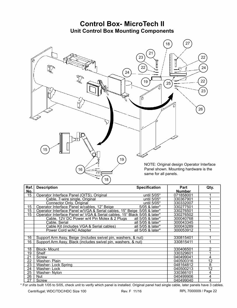
Ref. Description Specification Part Qty. No. Number 15 Operator Interface Panel (OITS), Original until 5/05* 071858001 1 Cable, 7-wire single, Original until 5/05* 330367901 1 Connector Only, Original until 5/05* 330332007 1 15 Operator Interface Panel w/cables, 12” Beige 5/05 & later* 330277501 1 15 Operator Interface Panel w/VGA & Serial cables, 15” Beige 5/05 & later* 330276501 1 15 Operator Interface Panel w/ VGA & Serial cables, 15” Black 5/05 & later* 330276502 1 Cable, 12V DC Power w/4 Pin Molex & 2 Plugs all 5/05 & later* 300040768 1 Cable, Serial all 5/05 & later* 300043345 1 Cable Kit (includes VGA & Serial cables) all 5/05 & later* 300043289 1 Power Cord w/AC Adapter all 5/05 & later* 300053912 1
16 Support Arm Assy, Beige (includes swivel pin, washers, & nut) 330815401 1 16 Support Arm Assy, Black (includes swivel pin, washers, & nut) 330815411 1
18 Block- Mount 330406501 2 19 Shelf 330329601 1 21 Screw 040499041 4 22 Washer- Plain 040500316 12 23 Washer- Lock Spring 048164812 8 24 Washer- Lock 040500213 12 25 Washer- Nylon 330366101 4 26 Nut 040499906 4 27 Screw 040499040 4
* For units built 1/05 to 5/05, check unit to verify which panel is installed. Original panel had single cable, later panels have 3 cables.
RPL 7000009 / Page 23Centrifugal; WDC/TDC/HDC Size 100 Rev. F 11/16
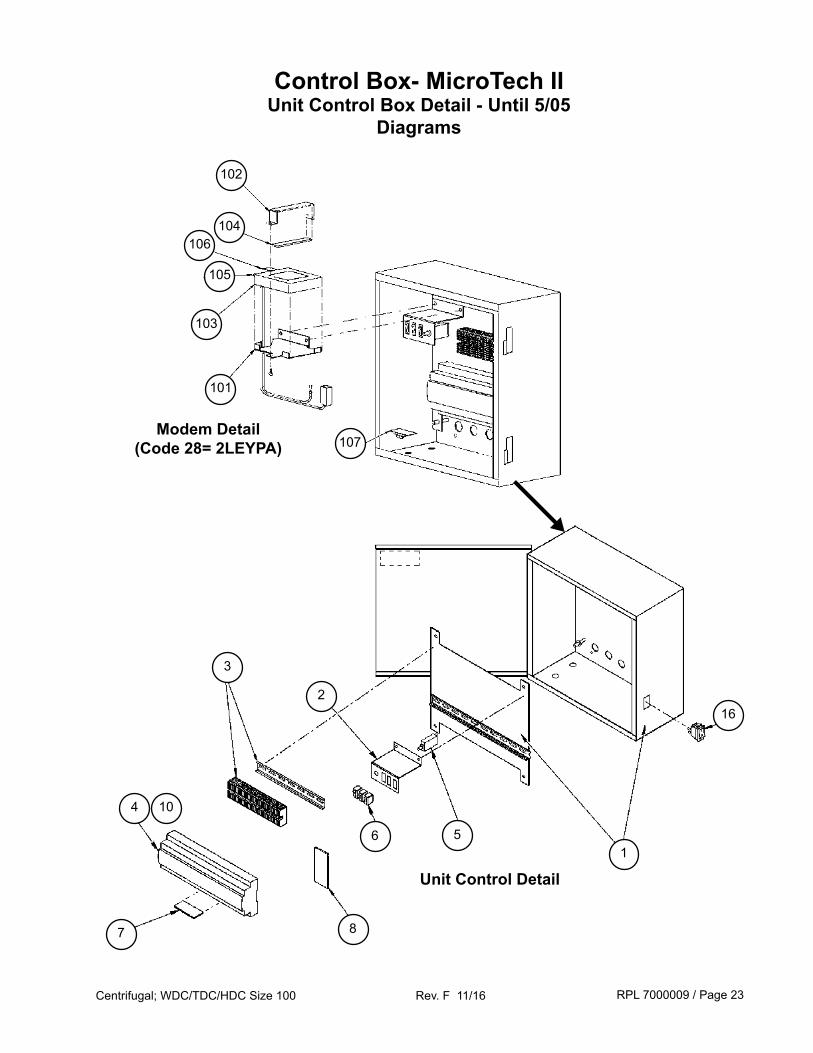
Control Box- MicroTech IIUnit Control Box Detail - Until 5/05
Diagrams
102
▼
104106
105
103
101
107
16
15
2
6
3
8
4
7
10
Modem Detail(Code 28= 2LEYPA)
Unit Control Detail
RPL 7000009 / Page 24Centrifugal; WDC/TDC/HDC Size 100 Rev. F 11/16
N/S= Not Shown on diagram.1 Controller must be programmed before shipping. Unit serial number and software code (located on controller label) are required when ordering to insure proper software installation. * This control box was used with the original design opeartor interface panel (which is connected to the control box with one seven-wire cable). A new design flat screen operator interface panel can be retrofitted for use with this control box using retrofit kit p/n 300040547.
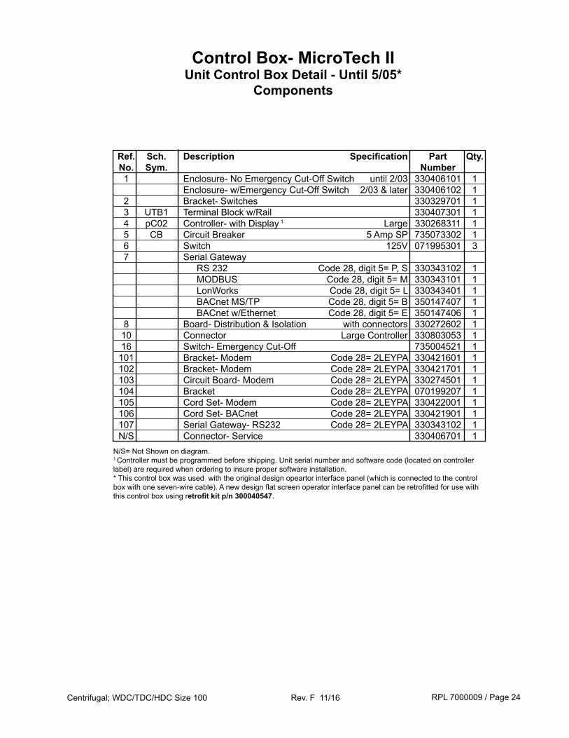
Control Box- MicroTech IIUnit Control Box Detail - Until 5/05*
Components
Ref. Sch. Description Specification Part Qty. No. Sym. Number 1 Enclosure- No Emergency Cut-Off Switch until 2/03 330406101 1 Enclosure- w/Emergency Cut-Off Switch 2/03 & later 330406102 1 2 Bracket- Switches 330329701 1 3 UTB1 Terminal Block w/Rail 330407301 1 4 pC02 Controller- with Display 1 Large 330268311 1 5 CB Circuit Breaker 5 Amp SP 735073302 1 6 Switch 125V 071995301 3 7 Serial Gateway RS 232 Code 28, digit 5= P, S 330343102 1 MODBUS Code 28, digit 5= M 330343101 1 LonWorks Code 28, digit 5= L 330343401 1 BACnet MS/TP Code 28, digit 5= B 350147407 1 BACnet w/Ethernet Code 28, digit 5= E 350147406 1 8 Board- Distribution & Isolation with connectors 330272602 1 10 Connector Large Controller 330803053 1 16 Switch- Emergency Cut-Off 735004521 1 101 Bracket- Modem Code 28= 2LEYPA 330421601 1 102 Bracket- Modem Code 28= 2LEYPA 330421701 1 103 Circuit Board- Modem Code 28= 2LEYPA 330274501 1 104 Bracket Code 28= 2LEYPA 070199207 1 105 Cord Set- Modem Code 28= 2LEYPA 330422001 1 106 Cord Set- BACnet Code 28= 2LEYPA 330421901 1 107 Serial Gateway- RS232 Code 28= 2LEYPA 330343102 1 N/S Connector- Service 330406701 1
RPL 7000009 / Page 25Centrifugal; WDC/TDC/HDC Size 100 Rev. F 11/16
12
22
16
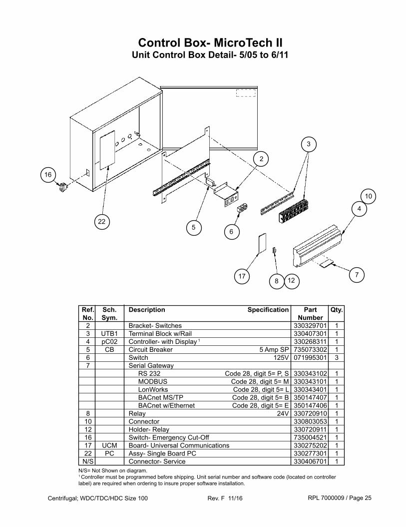
Control Box- MicroTech IIUnit Control Box Detail- 5/05 to 6/11
7
10
17
2
8
3
5 6
4
Ref. Sch. Description Specification Part Qty. No. Sym. Number 2 Bracket- Switches 330329701 1 3 UTB1 Terminal Block w/Rail 330407301 1 4 pC02 Controller- with Display 1 330268311 1 5 CB Circuit Breaker 5 Amp SP 735073302 1 6 Switch 125V 071995301 3 7 Serial Gateway RS 232 Code 28, digit 5= P, S 330343102 1 MODBUS Code 28, digit 5= M 330343101 1 LonWorks Code 28, digit 5= L 330343401 1 BACnet MS/TP Code 28, digit 5= B 350147407 1 BACnet w/Ethernet Code 28, digit 5= E 350147406 1 8 Relay 24V 330720910 1 10 Connector 330803053 1 12 Holder- Relay 330720911 1 16 Switch- Emergency Cut-Off 735004521 1 17 UCM Board- Universal Communications 330275202 1 22 PC Assy- Single Board PC 330277301 1 N/S Connector- Service 330406701 1N/S= Not Shown on diagram.1 Controller must be programmed before shipping. Unit serial number and software code (located on controller label) are required when ordering to insure proper software installation.
RPL 7000009 / Page 26Centrifugal; WDC/TDC/HDC Size 100 Rev. F 11/16
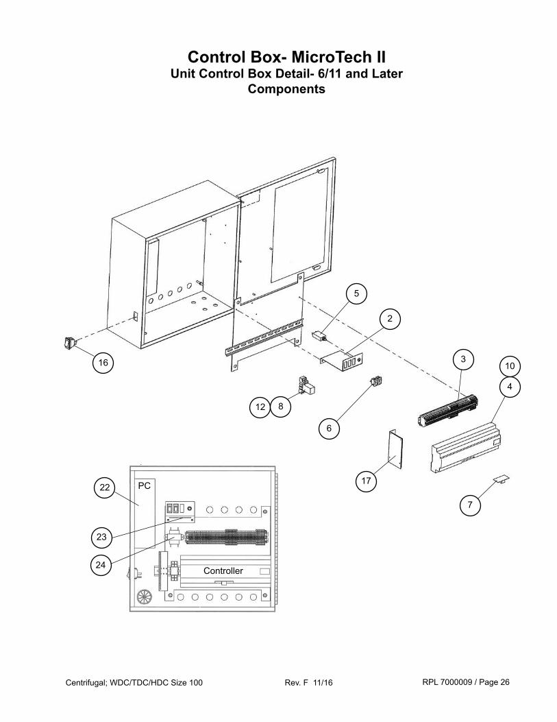
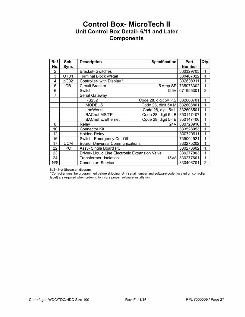
Control Box- MicroTech IIUnit Control Box Detail- 6/11 and Later
Components
24
22
23
Controller
PC
6
12
17
4
7
103
2
5
16
8
RPL 7000009 / Page 27Centrifugal; WDC/TDC/HDC Size 100 Rev. F 11/16
Control Box- MicroTech IIUnit Control Box Detail- 6/11 and Later
Components
N/S= Not Shown on diagram.1 Controller must be programmed before shipping. Unit serial number and software code (located on controller label) are required when ordering to insure proper software installation.
Ref. Sch. Description Specification Part Qty. No. Sym. Number 2 Bracket- Switches 330329703 1 3 UTB1 Terminal Block w/Rail 330407322 1 4 pC02 Controller- with Display 1 332608311 1 5 CB Circuit Breaker 5 Amp SP 735073302 1 6 Switch 125V 071995301 2 7 Serial Gateway RS232 Code 28, digit 5= P,S 332608701 1 MODBUS Code 28, digit 5= M 332608801 1 LonWorks Code 28, digit 5= L 332608501 1 BACnet MS/TP Code 28, digit 5= B 350147407 1 BACnet w/Ethernet Code 28, digit 5= E 350147406 1 8 Relay 24V 330720910 1 10 Connector Kit 333528053 1 12 Holder- Relay 330720911 1 16 Switch- Emergency Cut-Off 735004521 1 17 UCM Board- Universal Communications 330275202 1 22 PC Assy- Single Board PC 330276602 1 23 Driver- Liquid Line Electronic Expansion Valve 330277803 1 24 Transformer- Isolation 15VA 330277601 1 N/S Connector- Service 330406701 2
RPL 7000009 / Page 28Centrifugal; WDC/TDC/HDC Size 100 Rev. F 11/16
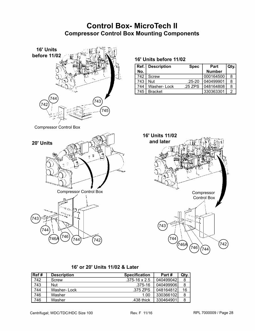
Ref # Description Specification Part # Qty. 742 Screw .375-16 x 2.5 040499042 8 743 Nut .375-16 040499906 8 744 Washer- Lock .375 ZPS 048164812 16 746 Washer 1.00 330366102 8 746 Washer .438 thick 330464901 8
Control Box- MicroTech IICompressor Control Box Mounting Components
742
16' Units before 11/02
16' Units 11/02and later20' Units
743
745
Compressor Control Box
744742
743
744
Compressor Control Box
746A746
743
744
742744746A 746
744
Ref. Description Spec Part Qty. No. Number 742 Screw 000164500 8 743 Nut .25-20 040499901 8 744 Washer- Lock .25 ZPS 048164808 8 745 Bracket 330363301 2
16' Units before 11/02
16' or 20' Units 11/02 & Later
Compressor Control Box
RPL 7000009 / Page 29Centrifugal; WDC/TDC/HDC Size 100 Rev. F 11/16
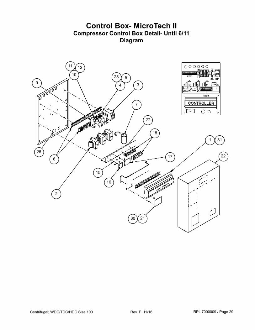
Control Box- MicroTech IICompressor Control Box Detail- Until 6/11
Diagram
10
11 12
4 39
6
2
7
27
18
15
16
17
1
21
22
31
30
528
26
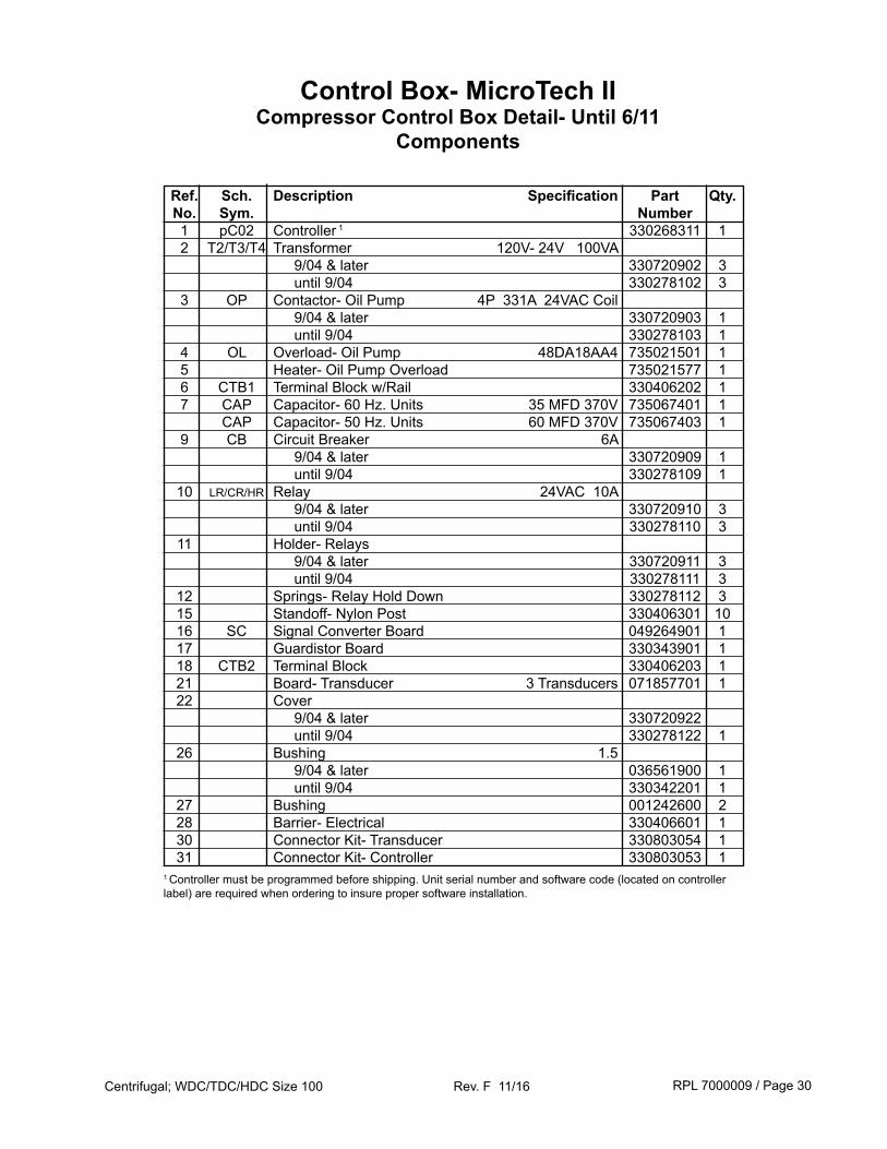
RPL 7000009 / Page 30Centrifugal; WDC/TDC/HDC Size 100 Rev. F 11/16
Control Box- MicroTech IICompressor Control Box Detail- Until 6/11
Components
Ref. Sch. Description Specification Part Qty. No. Sym. Number 1 pC02 Controller 1 330268311 1 2 T2/T3/T4 Transformer 120V- 24V 100VA 9/04 & later 330720902 3 until 9/04 330278102 3 3 OP Contactor- Oil Pump 4P 331A 24VAC Coil 9/04 & later 330720903 1 until 9/04 330278103 1 4 OL Overload- Oil Pump 48DA18AA4 735021501 1 5 Heater- Oil Pump Overload 735021577 1 6 CTB1 Terminal Block w/Rail 330406202 1 7 CAP Capacitor- 60 Hz. Units 35 MFD 370V 735067401 1 CAP Capacitor- 50 Hz. Units 60 MFD 370V 735067403 1 9 CB Circuit Breaker 6A 9/04 & later 330720909 1 until 9/04 330278109 1 10 LR/CR/HR Relay 24VAC 10A 9/04 & later 330720910 3 until 9/04 330278110 3 11 Holder- Relays 9/04 & later 330720911 3 until 9/04 330278111 3 12 Springs- Relay Hold Down 330278112 3 15 Standoff- Nylon Post 330406301 10 16 SC Signal Converter Board 049264901 1 17 Guardistor Board 330343901 1 18 CTB2 Terminal Block 330406203 1 21 Board- Transducer 3 Transducers 071857701 1 22 Cover 9/04 & later 330720922 until 9/04 330278122 1 26 Bushing 1.5 9/04 & later 036561900 1 until 9/04 330342201 1 27 Bushing 001242600 2 28 Barrier- Electrical 330406601 1 30 Connector Kit- Transducer 330803054 1 31 Connector Kit- Controller 330803053 11 Controller must be programmed before shipping. Unit serial number and software code (located on controller label) are required when ordering to insure proper software installation.
RPL 7000009 / Page 31Centrifugal; WDC/TDC/HDC Size 100 Rev. F 11/16
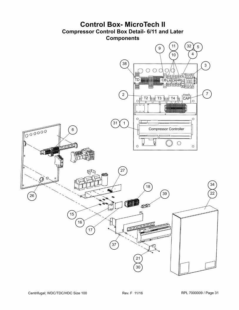
Control Box- MicroTech IICompressor Control Box Detail- 6/11 and Later
Components
2
9
38
30
21
16
37
4
532
3
7
10
15
18
27
39 22
34
17
6
26
CAP
TD CB
T2 T3 T4
CRLR HROL
Compressor Controller131
11
RPL 7000009 / Page 32Centrifugal; WDC/TDC/HDC Size 100 Rev. F 11/16
Control Box- MicroTech IICompressor Control Box Detail- 6/11 and Later
Components
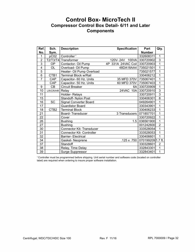
Ref. Sch. Description Specification Part Qty. No. Sym. Number 1 pC02 Controller 1 332608311 1 2 T2/T3/T4 Transformer 120V- 24V 100VA 330720902 3 3 OP Contactor- Oil Pump 4P 331A 24VAC Coil 330720903 1 4 OL Overload- Oil Pump 48DA18AA4 735021501 1 5 Heater- Oil Pump Overload 735021577 1 6 CTB1 Terminal Block w/Rail 330406212 1 7 CAP Capacitor- 60 Hz. Units 35 MFD 370V 735067401 1 CAP Capacitor- 50 Hz. Units 60 MFD 370V 735067403 1 9 CB Circuit Breaker 6A 330720909 1 10 LR/CR/HR Relay 24VAC 10A 330720910 3 11 Holder- Relays 330720911 3 15 Standoff- Nylon Post 330406301 8 16 SC Signal Converter Board 049264901 1 17 Guardistor Board 330343901 1 18 CTB2 Terminal Block 330406233 1 21 Board- Transducer 3 Transducers 071857701 1 22 Cover 330720922 1 26 Bushing 1.5 036561900 1 27 Bushing 001242600 2 30 Connector Kit- Transducer 333528054 1 31 Connector Kit- Controller 333528053 1 32 Barrier- Electrical 330406601 1 34 Gasket- Neoprene .125 x .750 070199209 1.7 ft. 37 Standoff 330328601 2 38 Relay, Time Delay 332843301 1 39 Surge Suppressor 332843401 11 Controller must be programmed before shipping. Unit serial number and software code (located on controller label) are required when ordering to insure proper software installation.
RPL 7000009 / Page 33Centrifugal; WDC/TDC/HDC Size 100 Rev. F 11/16
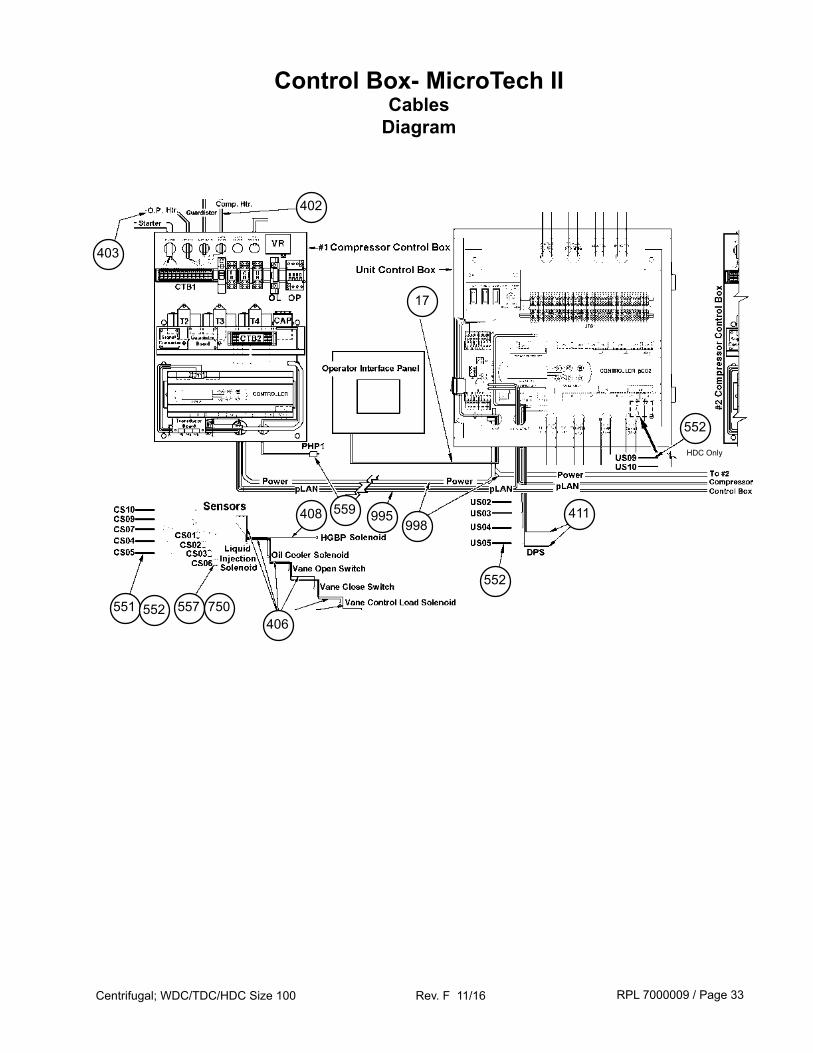
Control Box- MicroTech IICables
Diagram
551 552 557
408
552
411
552
995998
17
403
402
750
HDC Only
559
406
RPL 7000009 / Page 34Centrifugal; WDC/TDC/HDC Size 100 Rev. F 11/16
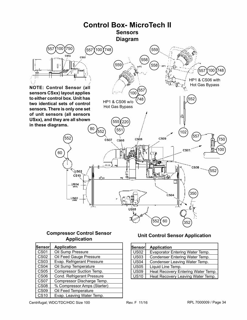
Sensor Application US02 Evaporator Entering Water Temp. US03 Condenser Entering Water Temp. US04 Condenser Leaving Water Temp. US05 Liquid Line Temp. US09 Heat Recovery Entering Water Temp. US10 Heat Recovery Leaving Water Temp.
Unit Control Sensor Application
Sensor Application CS01 Oil Sump Pressure CS02 Oil Feed Gauge Pressure CS03 Evap. Refrigerant Pressure CS04 Oil Sump Temperature CS05 Compressor Suction Temp. CS06 Cond. Refrigerant Pressure CS07 Compressor Discharge Temp. CS08 % Compressor Amps (Starter) CS09 Oil Feed Temperature CS10 Evap. Leaving Water Temp.
Compressor Control Sensor Application
552
552 60
350
558
750
552
100
80 551
60
552
557 100 748
102
552
352
Control Box- MicroTech IISensorsDiagram
557
559
557 100 750
557100
748
559
558557 100 748
HP1 & CS06 w/o Hot Gas Bypass
HP1 & CS06 withHot Gas Bypass
555 220
NOTE: Control Sensor (all sensors CSxx) layout applies to either control box. Unit has two identical sets of control sensors. There is only one set of unit sensors (all sensors USxx), and they are all shown in these diagrams.
RPL 7000009 / Page 35Centrifugal; WDC/TDC/HDC Size 100 Rev. F 11/16
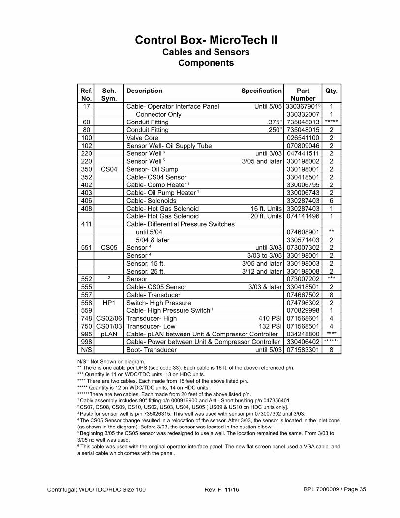
Ref. Sch. Description Specification Part Qty. No. Sym. Number 17 Cable- Operator Interface Panel Until 5/05 3303679016 1 Connector Only 330332007 1 60 Conduit Fitting .375" 735048013 ***** 80 Conduit Fitting .250" 735048015 2 100 Valve Core 026541100 2 102 Sensor Well- Oil Supply Tube 070809046 2 220 Sensor Well 3 until 3/03 047441511 2 220 Sensor Well 5 3/05 and later 330198002 2 350 CS04 Sensor- Oil Sump 330198001 2 352 Cable- CS04 Sensor 330418501 2 402 Cable- Comp Heater 1 330006795 2 403 Cable- Oil Pump Heater 1 330006743 2 406 Cable- Solenoids 330287403 6 408 Cable- Hot Gas Solenoid 16 ft. Units 330287403 1 Cable- Hot Gas Solenoid 20 ft. Units 074141496 1 411 Cable- Differential Pressure Switches until 5/04 074608901 ** 5/04 & later 330571403 2 551 CS05 Sensor 4 until 3/03 073007302 2 Sensor 4 3/03 to 3/05 330198001 2 Sensor, 15 ft. 3/05 and later 330198003 2 Sensor, 25 ft. 3/12 and later 330198008 2 552 2 Sensor 073007202 *** 555 Cable- CS05 Sensor 3/03 & later 330418501 2 557 Cable- Transducer 074667502 8 558 HP1 Switch- High Pressure 074796302 2 559 Cable- High Pressure Switch 1 070829998 1 748 CS02/06 Transducer- High 410 PSI 071568601 4 750 CS01/03 Transducer- Low 132 PSI 071568501 4 995 pLAN Cable- pLAN between Unit & Compressor Controller 034248800 **** 998 Cable- Power between Unit & Compressor Controller 330406402 ****** N/S Boot- Transducer until 5/03 071583301 8
Control Box- MicroTech IICables and Sensors
Components
N/S= Not Shown on diagram.** There is one cable per DPS (see code 33). Each cable is 16 ft. of the above referenced p/n.*** Quantity is 11 on WDC/TDC units, 13 on HDC units.**** There are two cables. Each made from 15 feet of the above listed p/n.***** Quantity is 12 on WDC/TDC units, 14 on HDC units.******There are two cables. Each made from 20 feet of the above listed p/n.1 Cable assembly includes 90° fitting p/n 000916900 and Anti- Short bushing p/n 047356401.2 CS07, CS08, CS09, CS10, US02, US03, US04, US05 [ US09 & US10 on HDC units only].3 Paste for sensor well is p/n 735026315. This well was used with sensor p/n 073007302 until 3/03.4 The CS05 Sensor change resulted in a relocation of the sensor. After 3/03, the sensor is located in the inlet cone (as shown in the diagram). Before 3/03, the sensor was located in the suction elbow.5 Beginning 3/05 the CS05 sensor was redesigned to use a well. The location remained the same. From 3/03 to 3/05 no well was used.6 This cable was used with the original operator interface panel. The new flat screen panel used a VGA cable and a serial cable which comes with the panel.
RPL 7000009 / Page 36Centrifugal; WDC/TDC/HDC Size 100 Rev. F 11/16
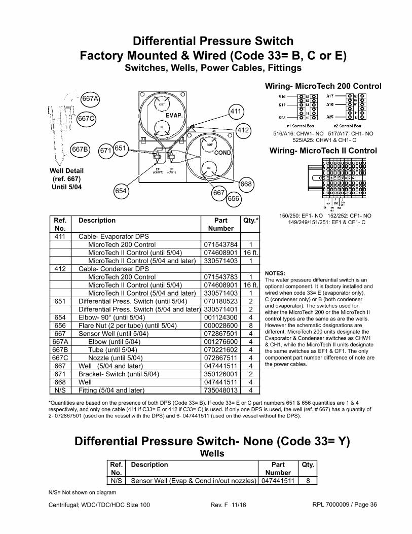
Differential Pressure SwitchFactory Mounted & Wired (Code 33= B, C or E)
Switches, Wells, Power Cables, Fittings
667656
411
651
Wiring- MicroTech 200 Control
Wiring- MicroTech II Control
NOTES:The water pressure differential switch is an optional component. It is factory installed and wired when code 33= E (evaporator only), C (condenser only) or B (both condenser and evaporator). The switches used for either the MicroTech 200 or the MicroTech II control types are the same as are the wells. However the schematic designations are different. MicroTech 200 units designate the Evaporator & Condenser switches as CHW1 & CH1, while the MicroTech II units designate the same switches as EF1 & CF1. The only component part number difference of note are the power cables.
412
Ref. Description Part Qty.* No. Number 411 Cable- Evaporator DPS MicroTech 200 Control 071543784 1 MicroTech II Control (until 5/04) 074608901 16 ft. MicroTech II Control (5/04 and later) 330571403 1 412 Cable- Condenser DPS MicroTech 200 Control 071543783 1 MicroTech II Control (until 5/04) 074608901 16 ft. MicroTech II Control (5/04 and later) 330571403 1 651 Differential Press. Switch (until 5/04) 070180523 2 Differential Press. Switch (5/04 and later) 330571401 2 654 Elbow- 90° (until 5/04) 001124300 4 656 Flare Nut (2 per tube) (until 5/04) 000028600 8 667 Sensor Well (until 5/04) 072867501 4 667A Elbow (until 5/04) 001276600 4 667B Tube (until 5/04) 070221602 4 667C Nozzle (until 5/04) 072867511 4 667 Well (5/04 and later) 047441511 4 671 Bracket- Switch (until 5/04) 350126001 2 668 Well 047441511 4 N/S Fitting (5/04 and later) 735048013 4
654
*Quantities are based on the presence of both DPS (Code 33= B). If code 33= E or C part numbers 651 & 656 quantities are 1 & 4 respectively, and only one cable (411 if C33= E or 412 if C33= C) is used. If only one DPS is used, the well (ref. # 667) has a quantity of 2- 072867501 (used on the vessel with the DPS) and 6- 047441511 (used on the vessel without the DPS).
667B
667C
667A
Well Detail (ref. 667)Until 5/04
Differential Pressure Switch- None (Code 33= Y)Wells
Ref. Description Part Qty. No. Number N/S Sensor Well (Evap & Cond in/out nozzles) 047441511 8
N/S= Not shown on diagram
668
671
516/A16: CHW1- NO 517/A17: CH1- NO 525/A25: CHW1 & CH1- C
150/250: EF1- NO 152/252: CF1- NO 149/249/151/251: EF1 & CF1- C
RPL 7000009 / Page 37Centrifugal; WDC/TDC/HDC Size 100 Rev. F 11/16
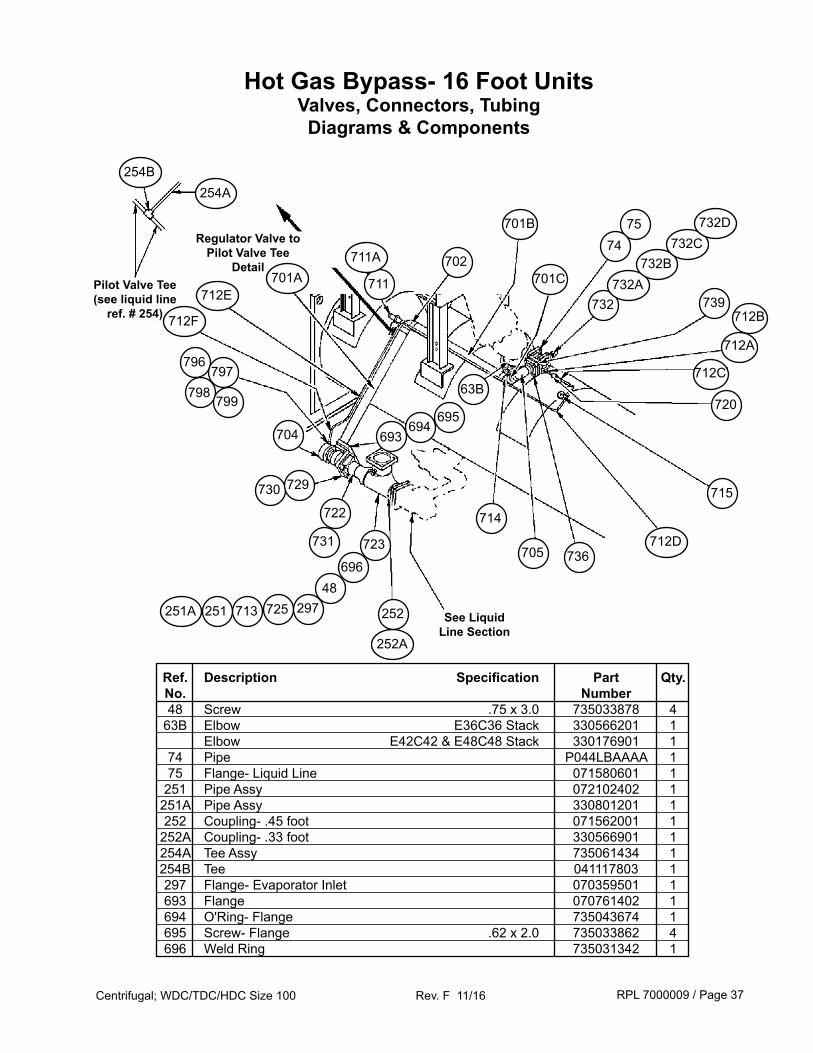
Hot Gas Bypass- 16 Foot UnitsValves, Connectors, TubingDiagrams & Components
701C
732
See Liquid Line Section
731
722
75
704
739711
74
715
705
730
702
725
723736
720
714
729
712E
796797
798799
712D
712A
732A732B
732C
713
696
297
63B
694693
695
712C
Ref. Description Specification Part Qty. No. Number 48 Screw .75 x 3.0 735033878 4 63B Elbow E36C36 Stack 330566201 1 Elbow E42C42 & E48C48 Stack 330176901 1 74 Pipe P044LBAAAA 1 75 Flange- Liquid Line 071580601 1 251 Pipe Assy 072102402 1 251A Pipe Assy 330801201 1 252 Coupling- .45 foot 071562001 1 252A Coupling- .33 foot 330566901 1 254A Tee Assy 735061434 1 254B Tee 041117803 1 297 Flange- Evaporator Inlet 070359501 1 693 Flange 070761402 1 694 O'Ring- Flange 735043674 1 695 Screw- Flange .62 x 2.0 735033862 4 696 Weld Ring 735031342 1
Pilot Valve Tee (see liquid line
ref. # 254)
254A254B
711A701A
251A
48
252A
252
Regulator Valve to Pilot Valve Tee
Detail
251
712F 712B
732D701B
RPL 7000009 / Page 38Centrifugal; WDC/TDC/HDC Size 100 Rev. F 11/16
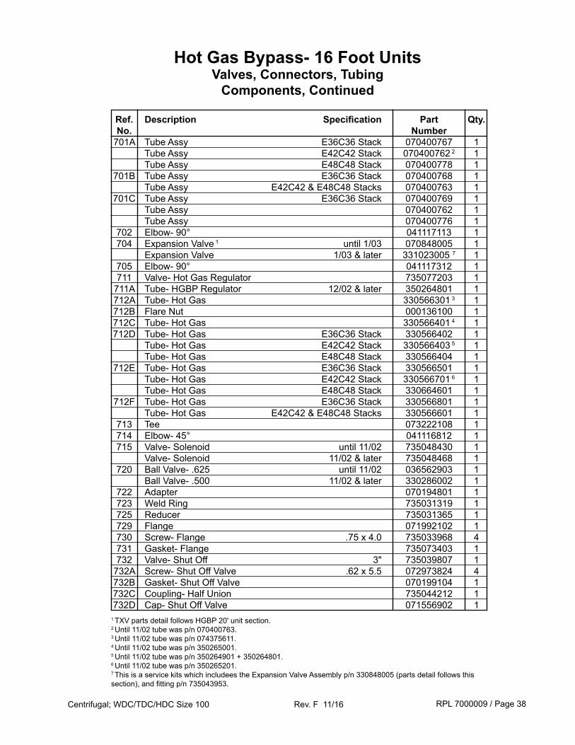
Hot Gas Bypass- 16 Foot UnitsValves, Connectors, Tubing
Components, Continued
Ref. Description Specification Part Qty. No. Number 701A Tube Assy E36C36 Stack 070400767 1 Tube Assy E42C42 Stack 070400762 2 1 Tube Assy E48C48 Stack 070400778 1 701B Tube Assy E36C36 Stack 070400768 1 Tube Assy E42C42 & E48C48 Stacks 070400763 1 701C Tube Assy E36C36 Stack 070400769 1 Tube Assy 070400762 1 Tube Assy 070400776 1 702 Elbow- 90° 041117113 1 704 Expansion Valve 1 until 1/03 070848005 1 Expansion Valve 1/03 & later 331023005 7 1 705 Elbow- 90° 041117312 1 711 Valve- Hot Gas Regulator 735077203 1 711A Tube- HGBP Regulator 12/02 & later 350264801 1 712A Tube- Hot Gas 330566301 3 1 712B Flare Nut 000136100 1 712C Tube- Hot Gas 330566401 4 1 712D Tube- Hot Gas E36C36 Stack 330566402 1 Tube- Hot Gas E42C42 Stack 330566403 5 1 Tube- Hot Gas E48C48 Stack 330566404 1 712E Tube- Hot Gas E36C36 Stack 330566501 1 Tube- Hot Gas E42C42 Stack 330566701 6 1 Tube- Hot Gas E48C48 Stack 330664601 1 712F Tube- Hot Gas E36C36 Stack 330566801 1 Tube- Hot Gas E42C42 & E48C48 Stacks 330566601 1 713 Tee 073222108 1 714 Elbow- 45° 041116812 1 715 Valve- Solenoid until 11/02 735048430 1 Valve- Solenoid 11/02 & later 735048468 1 720 Ball Valve- .625 until 11/02 036562903 1 Ball Valve- .500 11/02 & later 330286002 1 722 Adapter 070194801 1 723 Weld Ring 735031319 1 725 Reducer 735031365 1 729 Flange 071992102 1 730 Screw- Flange .75 x 4.0 735033968 4 731 Gasket- Flange 735073403 1 732 Valve- Shut Off 3" 735039807 1 732A Screw- Shut Off Valve .62 x 5.5 072973824 4 732B Gasket- Shut Off Valve 070199104 1 732C Coupling- Half Union 735044212 1 732D Cap- Shut Off Valve 071556902 11 TXV parts detail follows HGBP 20' unit section.2 Until 11/02 tube was p/n 070400763.3 Until 11/02 tube was p/n 074375611.4 Until 11/02 tube was p/n 350265001.5 Until 11/02 tube was p/n 350264901 + 350264801.6 Until 11/02 tube was p/n 350265201.7 This is a service kits which includees the Expansion Valve Assembly p/n 330848005 (parts detail follows this section), and fitting p/n 735043953.
RPL 7000009 / Page 39Centrifugal; WDC/TDC/HDC Size 100 Rev. F 11/16
Hot Gas Bypass- 16 Foot UnitsValves, Connectors, Tubing
Components, Continued
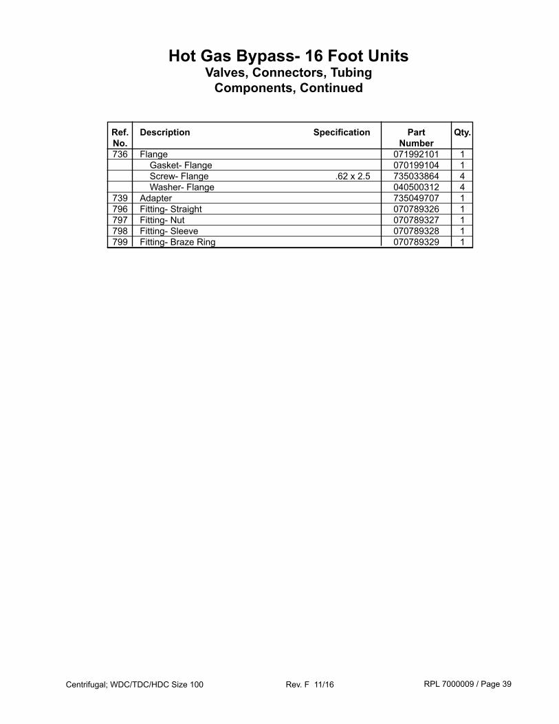
Ref. Description Specification Part Qty. No. Number 736 Flange 071992101 1 Gasket- Flange 070199104 1 Screw- Flange .62 x 2.5 735033864 4 Washer- Flange 040500312 4 739 Adapter 735049707 1 796 Fitting- Straight 070789326 1 797 Fitting- Nut 070789327 1 798 Fitting- Sleeve 070789328 1 799 Fitting- Braze Ring 070789329 1
RPL 7000009 / Page 40Centrifugal; WDC/TDC/HDC Size 100 Rev. F 11/16
Hot Gas Bypass- 20 Foot UnitsValves, Connectors, TubingDiagrams & Components
741
736
730
705
728
739724 711
714
702
698
697
704
720
710
729722
732
714
727701
723
725696
701
715
713
737
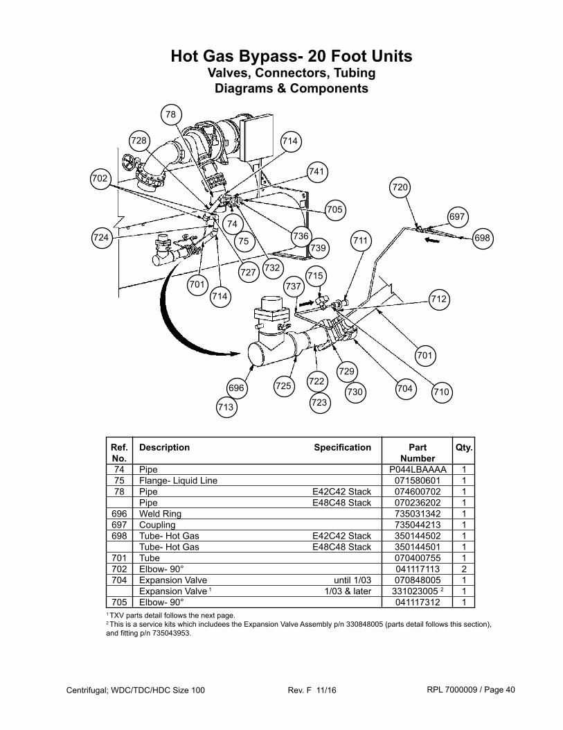
Ref. Description Specification Part Qty. No. Number 74 Pipe P044LBAAAA 1 75 Flange- Liquid Line 071580601 1 78 Pipe E42C42 Stack 074600702 1 Pipe E48C48 Stack 070236202 1 696 Weld Ring 735031342 1 697 Coupling 735044213 1 698 Tube- Hot Gas E42C42 Stack 350144502 1 Tube- Hot Gas E48C48 Stack 350144501 1 701 Tube 070400755 1 702 Elbow- 90° 041117113 2 704 Expansion Valve until 1/03 070848005 1 Expansion Valve 1 1/03 & later 331023005 2 1 705 Elbow- 90° 041117312 11 TXV parts detail follows the next page.2 This is a service kits which includees the Expansion Valve Assembly p/n 330848005 (parts detail follows this section), and fitting p/n 735043953.
712
74
75
78
RPL 7000009 / Page 41Centrifugal; WDC/TDC/HDC Size 100 Rev. F 11/16
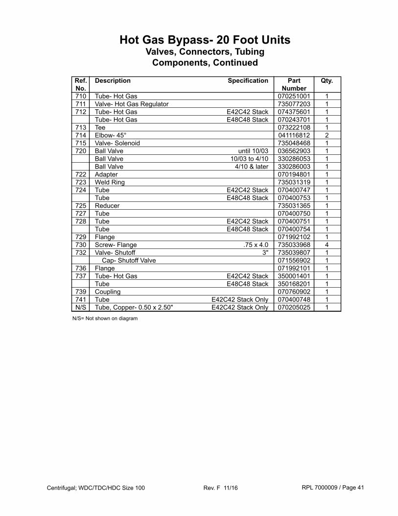
Ref. Description Specification Part Qty. No. Number 710 Tube- Hot Gas 070251001 1 711 Valve- Hot Gas Regulator 735077203 1 712 Tube- Hot Gas E42C42 Stack 074375601 1 Tube- Hot Gas E48C48 Stack 070243701 1 713 Tee 073222108 1 714 Elbow- 45° 041116812 2 715 Valve- Solenoid 735048468 1 720 Ball Valve until 10/03 036562903 1 Ball Valve 10/03 to 4/10 330286053 1 Ball Valve 4/10 & later 330286003 1 722 Adapter 070194801 1 723 Weld Ring 735031319 1 724 Tube E42C42 Stack 070400747 1 Tube E48C48 Stack 070400753 1 725 Reducer 735031365 1 727 Tube 070400750 1 728 Tube E42C42 Stack 070400751 1 Tube E48C48 Stack 070400754 1 729 Flange 071992102 1 730 Screw- Flange .75 x 4.0 735033968 4 732 Valve- Shutoff 3" 735039807 1 Cap- Shutoff Valve 071556902 1 736 Flange 071992101 1 737 Tube- Hot Gas E42C42 Stack 350001401 1 Tube E48C48 Stack 350168201 1 739 Coupling 070760902 1 741 Tube E42C42 Stack Only 070400748 1 N/S Tube, Copper- 0.50 x 2.50" E42C42 Stack Only 070205025 1
Hot Gas Bypass- 20 Foot UnitsValves, Connectors, Tubing
Components, Continued
N/S= Not shown on diagram
RPL 7000009 / Page 42Centrifugal; WDC/TDC/HDC Size 100 Rev. F 11/16
Hot Gas BypassExpansion Valve Detail
153
160
152
149146
157
145
147 144 151 143 150141
155 158
142
149
154
152
148
158
156152
142153
145
147 144143
150 141
160
153 151
142
154
155
152
153
146157
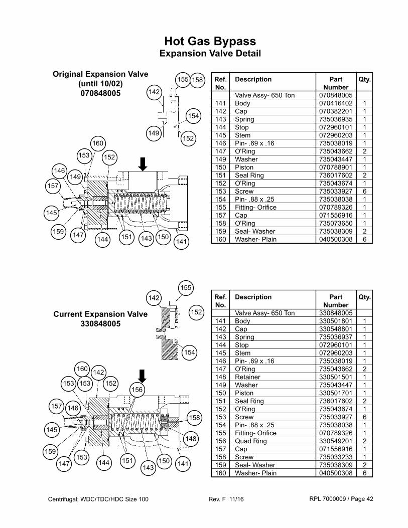
Ref. Description Part Qty. No. Number Valve Assy- 650 Ton 070848005 141 Body 070416402 1 142 Cap 070382201 1 143 Spring 735036935 1 144 Stop 072960101 1 145 Stem 072960203 1 146 Pin- .69 x .16 735038019 1 147 O'Ring 735043662 2 149 Washer 735043447 1 150 Piston 070788901 1 151 Seal Ring 736017602 2 152 O'Ring 735043674 1 153 Screw 735033927 6 154 Pin- .88 x .25 735038038 1 155 Fitting- Orifice 070789326 1 157 Cap 071556916 1 158 O'Ring 735073650 1 159 Seal- Washer 735038309 2 160 Washer- Plain 040500308 6
Ref. Description Part Qty. No. Number Valve Assy- 650 Ton 330848005 141 Body 330501801 1 142 Cap 330548801 1 143 Spring 735036937 1 144 Stop 072960101 1 145 Stem 072960203 1 146 Pin- .69 x .16 735038019 1 147 O'Ring 735043662 2 148 Retainer 330501501 1 149 Washer 735043447 1 150 Piston 330501701 1 151 Seal Ring 736017602 2 152 O'Ring 735043674 1 153 Screw 735033927 6 154 Pin- .88 x .25 735038038 1 155 Fitting- Orifice 070789326 1 156 Quad Ring 330549201 2 157 Cap 071556916 1 158 Screw 735033233 1 159 Seal- Washer 735038309 2 160 Washer- Plain 040500308 6
Original Expansion Valve(until 10/02)070848005
Current Expansion Valve330848005
159
159
RPL 7000009 / Page 43Centrifugal; WDC/TDC/HDC Size 100 Rev. F 11/16
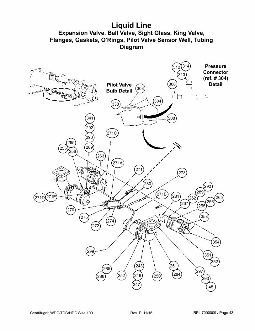
Liquid LineExpansion Valve, Ball Valve, Sight Glass, King Valve,
Flanges, Gaskets, O'Rings, Pilot Valve Sensor Well, TubingDiagram
338
Pilot Valve Bulb Detail
272
303308
312
313
314 Pressure Connector (ref. # 304)
Detail
304
300
281271D
256
354
351
353
292
255265
289
297251
250286
285
299
252
274
352
293
280
263271A
48
246
243
271E
271
290
247
256
292
267262
289
255
275
270
271B
284
271C
273
265
341
RPL 7000009 / Page 44Centrifugal; WDC/TDC/HDC Size 100 Rev. F 11/16
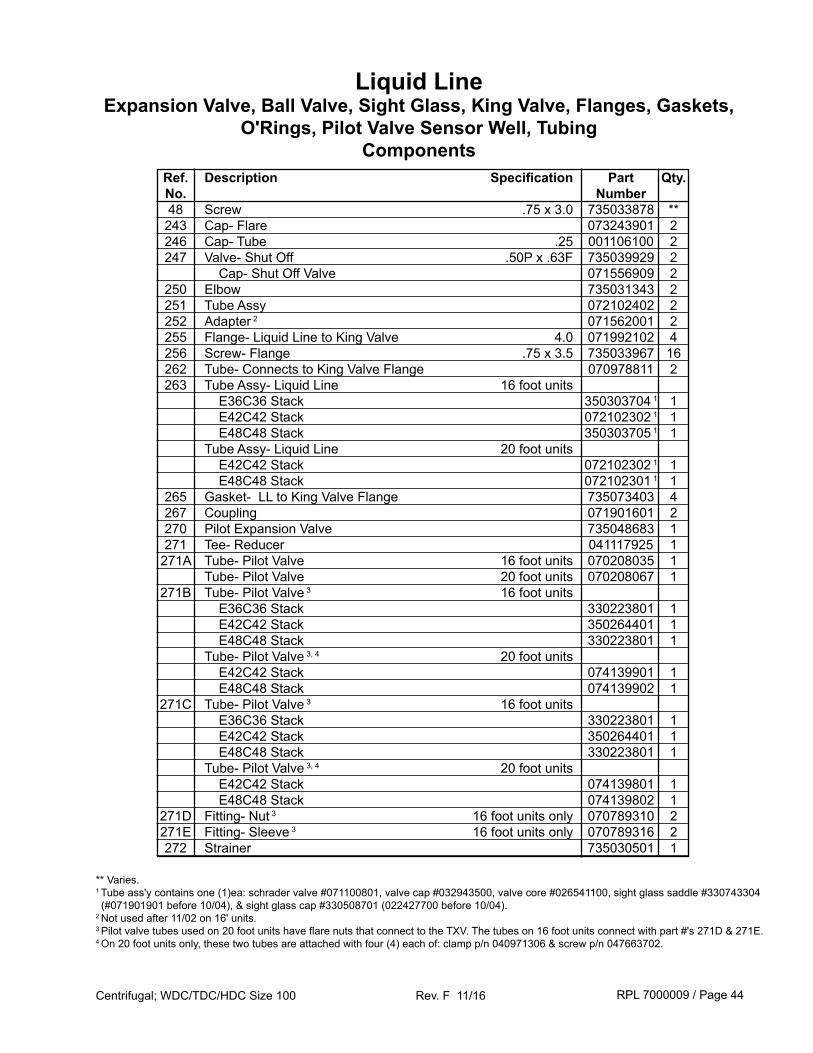
Ref. Description Specification Part Qty. No. Number 48 Screw .75 x 3.0 735033878 ** 243 Cap- Flare 073243901 2 246 Cap- Tube .25 001106100 2 247 Valve- Shut Off .50P x .63F 735039929 2 Cap- Shut Off Valve 071556909 2 250 Elbow 735031343 2 251 Tube Assy 072102402 2 252 Adapter 2 071562001 2 255 Flange- Liquid Line to King Valve 4.0 071992102 4 256 Screw- Flange .75 x 3.5 735033967 16 262 Tube- Connects to King Valve Flange 070978811 2 263 Tube Assy- Liquid Line 16 foot units E36C36 Stack 350303704 1 1 E42C42 Stack 072102302 1 1 E48C48 Stack 350303705 1 1 Tube Assy- Liquid Line 20 foot units E42C42 Stack 072102302 1 1 E48C48 Stack 072102301 1 1 265 Gasket- LL to King Valve Flange 735073403 4 267 Coupling 071901601 2 270 Pilot Expansion Valve 735048683 1 271 Tee- Reducer 041117925 1 271A Tube- Pilot Valve 16 foot units 070208035 1 Tube- Pilot Valve 20 foot units 070208067 1 271B Tube- Pilot Valve 3 16 foot units E36C36 Stack 330223801 1 E42C42 Stack 350264401 1 E48C48 Stack 330223801 1 Tube- Pilot Valve 3, 4 20 foot units E42C42 Stack 074139901 1 E48C48 Stack 074139902 1 271C Tube- Pilot Valve 3 16 foot units E36C36 Stack 330223801 1 E42C42 Stack 350264401 1 E48C48 Stack 330223801 1 Tube- Pilot Valve 3, 4 20 foot units E42C42 Stack 074139801 1 E48C48 Stack 074139802 1 271D Fitting- Nut 3 16 foot units only 070789310 2 271E Fitting- Sleeve 3 16 foot units only 070789316 2 272 Strainer 735030501 1
** Varies.1 Tube ass'y contains one (1)ea: schrader valve #071100801, valve cap #032943500, valve core #026541100, sight glass saddle #330743304 (#071901901 before 10/04), & sight glass cap #330508701 (022427700 before 10/04).2 Not used after 11/02 on 16' units.3 Pilot valve tubes used on 20 foot units have flare nuts that connect to the TXV. The tubes on 16 foot units connect with part #'s 271D & 271E.4 On 20 foot units only, these two tubes are attached with four (4) each of: clamp p/n 040971306 & screw p/n 047663702.
Liquid LineExpansion Valve, Ball Valve, Sight Glass, King Valve, Flanges, Gaskets,
O'Rings, Pilot Valve Sensor Well, Tubing Components
RPL 7000009 / Page 45Centrifugal; WDC/TDC/HDC Size 100 Rev. F 11/16
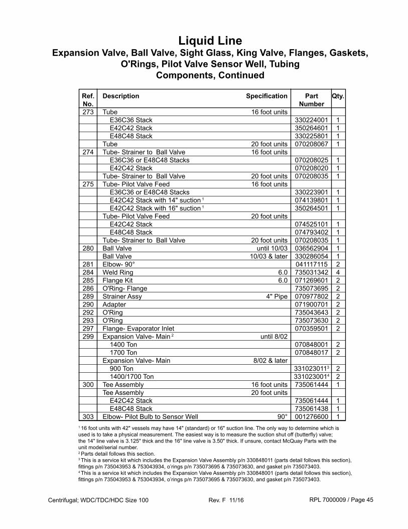
Ref. Description Specification Part Qty. No. Number 273 Tube 16 foot units E36C36 Stack 330224001 1 E42C42 Stack 350264601 1 E48C48 Stack 330225801 1 Tube 20 foot units 070208067 1 274 Tube- Strainer to Ball Valve 16 foot units E36C36 or E48C48 Stacks 070208025 1 E42C42 Stack 070208020 1 Tube- Strainer to Ball Valve 20 foot units 070208035 1 275 Tube- Pilot Valve Feed 16 foot units E36C36 or E48C48 Stacks 330223901 1 E42C42 Stack with 14" suction 1 074139801 1 E42C42 Stack with 16" suction 1 350264501 1 Tube- Pilot Valve Feed 20 foot units E42C42 Stack 074525101 1 E48C48 Stack 074793402 1 Tube- Strainer to Ball Valve 20 foot units 070208035 1 280 Ball Valve until 10/03 036562904 1 Ball Valve 10/03 & later 330286054 1 281 Elbow- 90° 041117115 2 284 Weld Ring 6.0 735031342 4 285 Flange Kit 6.0 071269601 2 286 O'Ring- Flange 735073695 2 289 Strainer Assy 4" Pipe 070977802 2 290 Adapter 071900701 2 292 O'Ring 735043643 2 293 O'Ring 735073630 2 297 Flange- Evaporator Inlet 070359501 2 299 Expansion Valve- Main 2 until 8/02 1400 Ton 070848001 2 1700 Ton 070848017 2 Expansion Valve- Main 8/02 & later 900 Ton 3310230113 2 1400/1700 Ton 3310230014 2 300 Tee Assembly 16 foot units 735061444 1 Tee Assembly 20 foot units E42C42 Stack 735061444 1 E48C48 Stack 735061438 1 303 Elbow- Pilot Bulb to Sensor Well 90° 001276600 11 16 foot units with 42" vessels may have 14" (standard) or 16" suction line. The only way to determine which is used is to take a physical measurement. The easiest way is to measure the suction shut off (butterfly) valve; the 14" line valve is 3.125" thick and the 16" line valve is 3.50" thick. If unsure, contact McQuay Parts with the unit model/serial number.2 Parts detail follows this section.3 This is a service kit which includes the Expansion Valve Assembly p/n 330848011 (parts detail follows this section), fittings p/n 735043953 & 753043934, o’rings p/n 735073695 & 735073630, and gasket p/n 735073403.4 This is a service kit which includes the Expansion Valve Assembly p/n 330848001 (parts detail follows this section), fittings p/n 735043953 & 753043934, o’rings p/n 735073695 & 735073630, and gasket p/n 735073403.
Liquid LineExpansion Valve, Ball Valve, Sight Glass, King Valve, Flanges, Gaskets,
O'Rings, Pilot Valve Sensor Well, Tubing Components, Continued
RPL 7000009 / Page 46Centrifugal; WDC/TDC/HDC Size 100 Rev. F 11/16
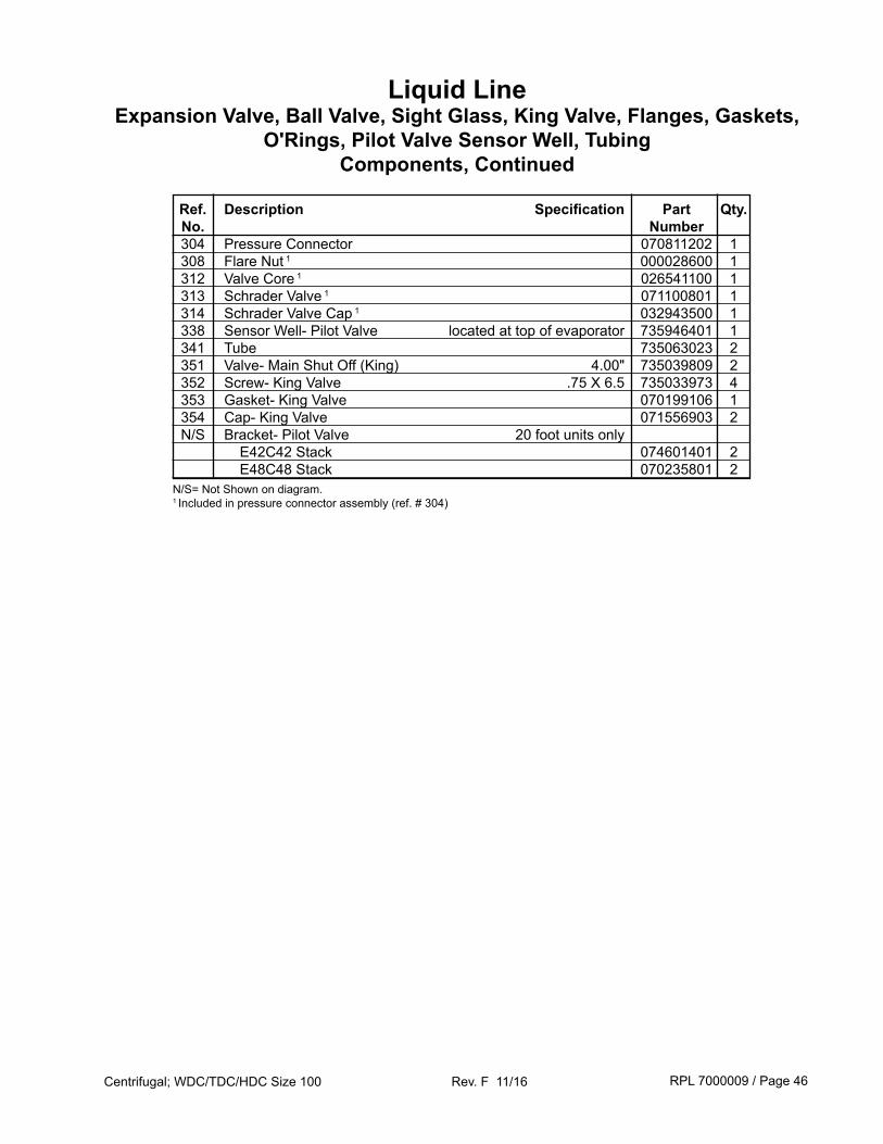
Ref. Description Specification Part Qty. No. Number 304 Pressure Connector 070811202 1 308 Flare Nut 1 000028600 1 312 Valve Core 1 026541100 1 313 Schrader Valve 1 071100801 1 314 Schrader Valve Cap 1 032943500 1 338 Sensor Well- Pilot Valve located at top of evaporator 735946401 1 341 Tube 735063023 2 351 Valve- Main Shut Off (King) 4.00" 735039809 2 352 Screw- King Valve .75 X 6.5 735033973 4 353 Gasket- King Valve 070199106 1 354 Cap- King Valve 071556903 2 N/S Bracket- Pilot Valve 20 foot units only E42C42 Stack 074601401 2 E48C48 Stack 070235801 2N/S= Not Shown on diagram.1 Included in pressure connector assembly (ref. # 304)
Liquid LineExpansion Valve, Ball Valve, Sight Glass, King Valve, Flanges, Gaskets,
O'Rings, Pilot Valve Sensor Well, Tubing Components, Continued
RPL 7000009 / Page 47Centrifugal; WDC/TDC/HDC Size 100 Rev. F 11/16
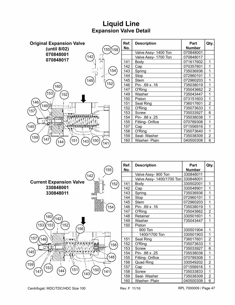
Liquid LineExpansion Valve Detail
Ref. Description Part Qty. No. Number Valve Assy- 1400 Ton 070848001 Valve Assy- 1700 Ton 070848017 141 Body 071617602 1 142 Cap 070357801 1 143 Spring 735036936 1 144 Stop 072960101 1 145 Stem 072960203 1 146 Pin- .69 x .16 735038019 1 147 O'Ring 735043662 2 149 Washer 735043447 1 150 Piston 073151603 1 151 Seal Ring 736017601 2 152 O'Ring 735073633 1 153 Screw 735033927 6 154 Pin- .88 x .25 735038038 1 155 Fitting- Orifice 070789308 1 157 Cap 071556916 1 158 O'Ring 735073640 1 159 Seal- Washer 735038309 2 160 Washer- Plain 040500308 6
Ref. Description Part Qty. No. Number Valve Assy- 900 Ton 330848011 Valve Assy- 1400/1700 Ton 330848001 141 Body 330502001 1 142 Cap 330548901 1 143 Spring 735036936 1 144 Stop 072960101 1 145 Stem 072960203 1 146 Pin- .69 x .16 735038019 1 147 O'Ring 735043662 2 148 Retainer 330501601 1 149 Washer 735043447 1 150 Piston 900 Ton 330501904 1 1400/1700 Ton 330501903 1 151 Seal Ring 736017601 2 152 O'Ring 735073633 1 153 Screw 735033927 6 154 Pin- .88 x .25 735038038 1 155 Fitting- Orifice 070789308 1 156 Quad Ring 330549202 2 157 Cap 071556916 1 158 Screw 735033833 1 159 Seal- Washer 735038309 2 160 Washer- Plain 040500308 6
Original Expansion Valve(until 8/02)070848001070848017
Current Expansion Valve330848001330848011
153
160
152
149146
157
145
147 144 151 143 150141
155 158
142
149
154
152
148
158
156152
142153
145
147 144143
150 141
160
153 151
142
154
155
152
153
146157
159
159
RPL 7000009 / Page 48Centrifugal; WDC/TDC/HDC Size 100 Rev. F 11/16
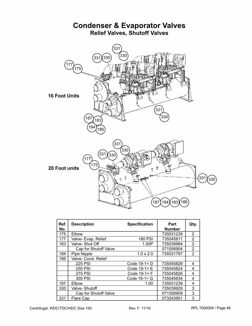
Condenser & Evaporator ValvesRelief Valves, Shutoff Valves
331
Ref. Description Specification Part Qty. No. Number 175 Elbow 735031239 2 177 Valve- Evap. Relief 180 PSI 735045811 2 183 Valve- Shut Off 1.00P 735039964 2 Cap for Shutoff Valve 071556904 2 184 Pipe Nipple 1.0 x 2.0 735031797 2 186 Valve- Cond. Relief 225 PSI Code 19-1= D 735045829 4 250 PSI Code 19-1= E 735045824 4 275 PSI Code 19-1= F 735045826 4 300 PSI Code 19-1= G 735045834 4 187 Elbow 1.00 735031239 4 330 Valve- Shutoff 735039929 3 Cap for Shutoff Valve 071556909 3 331 Flare Cap 073243901 3
330
177175
331 330
331 330
331 330
331
330
177175
331
330
186
183184
16 Foot Units
20 Foot units
187
186183184187
RPL 7000009 / Page 49Centrifugal; WDC/TDC/HDC Size 100 Rev. F 11/16
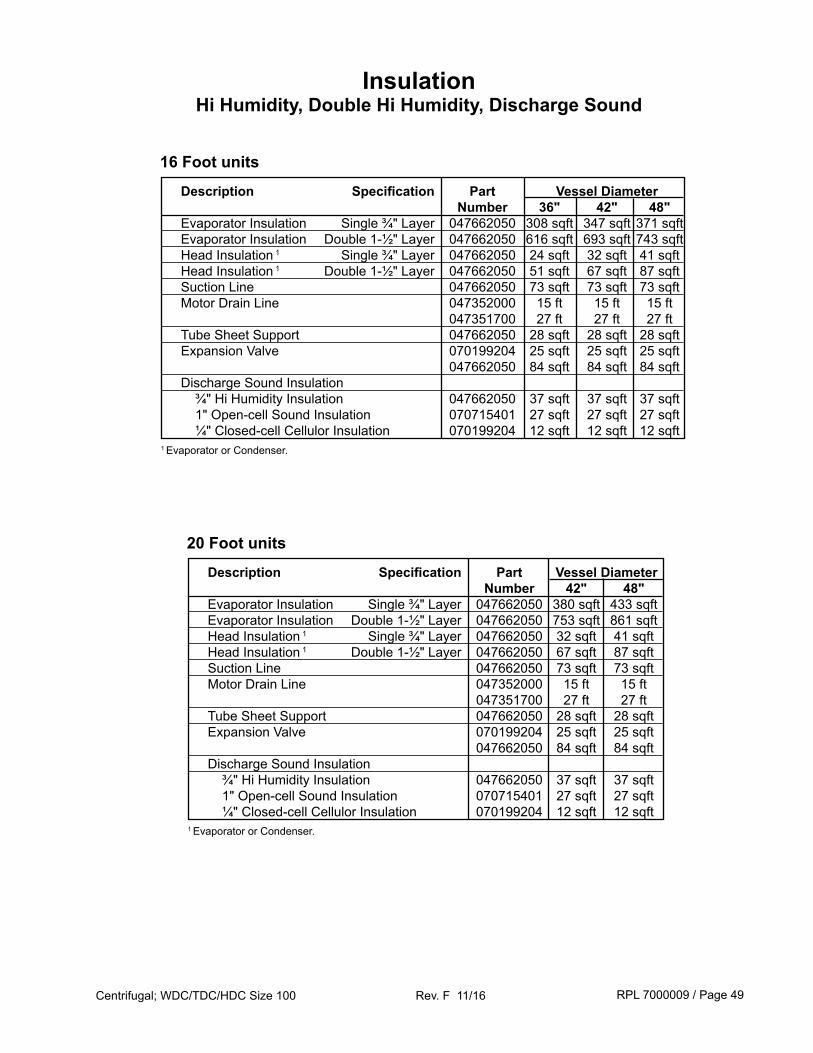
InsulationHi Humidity, Double Hi Humidity, Discharge Sound
Description Specification Part Vessel Diameter Number 36" 42" 48" Evaporator Insulation Single ¾" Layer 047662050 308 sqft 347 sqft 371 sqft Evaporator Insulation Double 1-½" Layer 047662050 616 sqft 693 sqft 743 sqft Head Insulation 1 Single ¾" Layer 047662050 24 sqft 32 sqft 41 sqft Head Insulation 1 Double 1-½" Layer 047662050 51 sqft 67 sqft 87 sqft Suction Line 047662050 73 sqft 73 sqft 73 sqft Motor Drain Line 047352000 15 ft 15 ft 15 ft 047351700 27 ft 27 ft 27 ft Tube Sheet Support 047662050 28 sqft 28 sqft 28 sqft Expansion Valve 070199204 25 sqft 25 sqft 25 sqft 047662050 84 sqft 84 sqft 84 sqft Discharge Sound Insulation ¾" Hi Humidity Insulation 047662050 37 sqft 37 sqft 37 sqft 1" Open-cell Sound Insulation 070715401 27 sqft 27 sqft 27 sqft ¼" Closed-cell Cellulor Insulation 070199204 12 sqft 12 sqft 12 sqft1 Evaporator or Condenser.
16 Foot units
Description Specification Part Vessel Diameter Number 42" 48" Evaporator Insulation Single ¾" Layer 047662050 380 sqft 433 sqft Evaporator Insulation Double 1-½" Layer 047662050 753 sqft 861 sqft Head Insulation 1 Single ¾" Layer 047662050 32 sqft 41 sqft Head Insulation 1 Double 1-½" Layer 047662050 67 sqft 87 sqft Suction Line 047662050 73 sqft 73 sqft Motor Drain Line 047352000 15 ft 15 ft 047351700 27 ft 27 ft Tube Sheet Support 047662050 28 sqft 28 sqft Expansion Valve 070199204 25 sqft 25 sqft 047662050 84 sqft 84 sqft Discharge Sound Insulation ¾" Hi Humidity Insulation 047662050 37 sqft 37 sqft 1" Open-cell Sound Insulation 070715401 27 sqft 27 sqft ¼" Closed-cell Cellulor Insulation 070199204 12 sqft 12 sqft1 Evaporator or Condenser.
20 Foot units
RPL 7000009 / Page 50Centrifugal; WDC/TDC/HDC Size 100 Rev. F 11/16
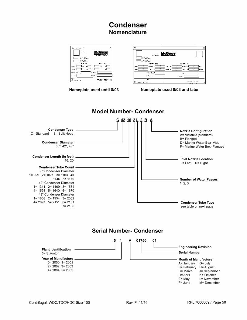
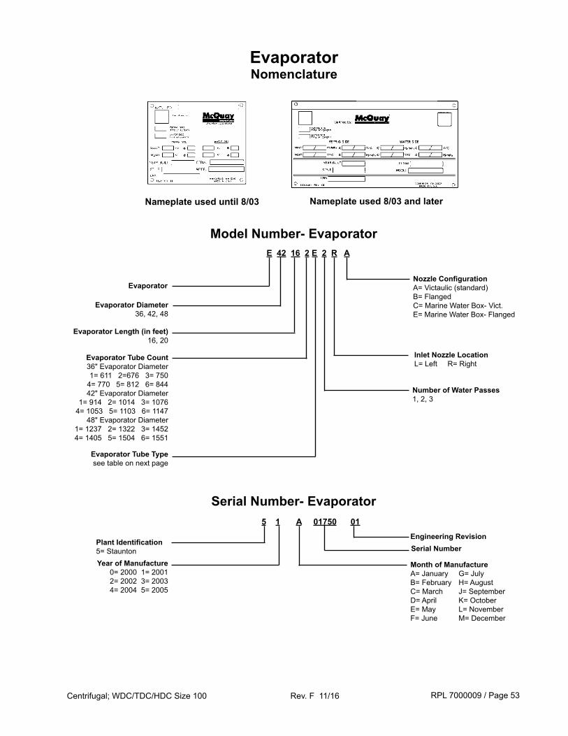
5 1 A 01750 01
Plant Identification 5= Staunton Serial Number
Year of Manufacture0= 2000 1= 2001 2= 2002 3= 2003 4= 2004 5= 2005
Month of ManufactureA= JanuaryB= FebruaryC= MarchD= AprilE= MayF= June
G= JulyH= AugustJ= SeptemberK= OctoberL= NovemberM= December
Serial Number- Condenser
Engineering Revision
CondenserNomenclature
Condenser Diameter36", 42", 48"
Model Number- CondenserC 42 16 2 L 2 R A
Number of Water Passes1, 2, 3
Condenser Length (in feet)16, 20
Condenser TypeC= Standard S= Split Head
Condenser Tube Count36" Condenser Diameter
1= 929 2= 1071 3= 1103 4= 1146 5= 1170
42" Condenser Diameter 1= 1341 2= 1469 3= 1554 4= 1593 5= 1640 6= 1670
48" Condenser Diameter1= 1858 2= 1954 3= 2052 4= 2097 5= 2151 6= 2131
7= 2186
Inlet Nozzle LocationL= Left R= Right
Nozzle ConfigurationA= Victaulic (standard)B= FlangedD= Marine Water Box- Vict.F= Marine Water Box- Flanged
Condenser Tube Typesee table on next page
Nameplate used until 8/03 Nameplate used 8/03 and later
RPL 7000009 / Page 51Centrifugal; WDC/TDC/HDC Size 100 Rev. F 11/16
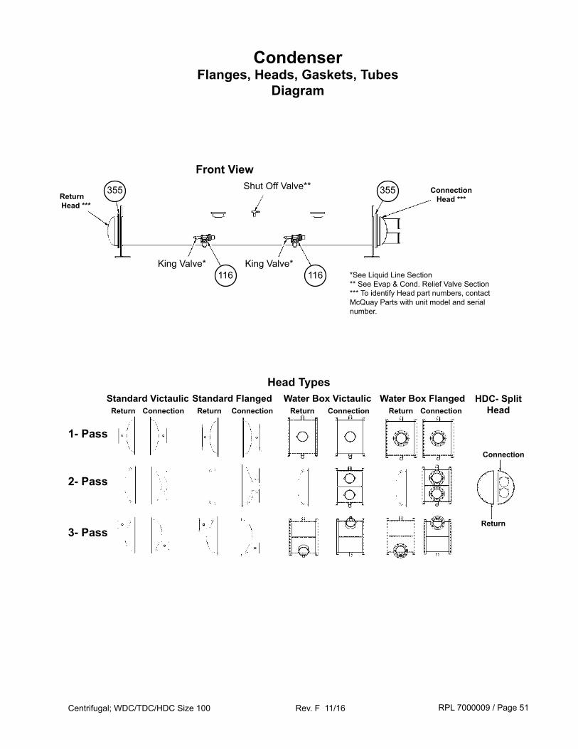
CondenserFlanges, Heads, Gaskets, Tubes
Diagram
Shut Off Valve**
King Valve*
355355
1- Pass
2- Pass
3- Pass
Standard Victaulic Standard Flanged Water Box Victaulic Water Box FlangedReturn Connection ConnectionReturn Return Connection Return Connection
Head Types
Front View
HDC- Split Head
Return
Connection
King Valve*116 116 *See Liquid Line Section
** See Evap & Cond. Relief Valve Section*** To identify Head part numbers, contact McQuay Parts with unit model and serial number.
ConnectionHead ***Return
Head ***
RPL 7000009 / Page 52Centrifugal; WDC/TDC/HDC Size 100 Rev. F 11/16
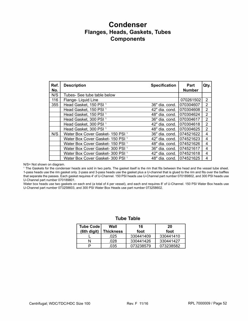
CondenserFlanges, Heads, Gaskets, Tubes
Components
Tube Code Wall 16 20 (6th digit) Thickness foot foot L .025 330441409 330441410 N .028 330441426 330441427 P .035 073238579 073238582
Tube Table
Ref. Description Specification Part Qty. No. Number N/S Tubes- See tube table below 116 Flange- Liquid Line 070261502 2 355 Head Gasket, 150 PSI 1 36" dia. cond. 070304607 2 Head Gasket, 150 PSI 1 42" dia. cond. 070304608 2 Head Gasket, 150 PSI 1 48" dia. cond. 070304624 2 Head Gasket, 300 PSI 1 36" dia. cond. 070304617 2 Head Gasket, 300 PSI 1 42" dia. cond. 070304618 2 Head Gasket, 300 PSI 1 48" dia. cond. 070304625 2 N/S Water Box Cover Gasket- 150 PSI 1 36" dia. cond. 074521622 4 Water Box Cover Gasket- 150 PSI 1 42" dia. cond. 074521623 4 Water Box Cover Gasket- 150 PSI 1 48" dia. cond. 074521626 4 Water Box Cover Gasket- 300 PSI 1 36" dia. cond. 074521617 4 Water Box Cover Gasket- 300 PSI 1 42" dia. cond. 074521618 4 Water Box Cover Gasket- 300 PSI 1 48" dia. cond. 074521625 4
N/S= Not shown on diagram. 1 The Gaskets for the condenser heads are sold in two parts. The gasket itself is the rim that fits between the head and the vessel tube sheet. 1-pass heads use the rim gasket only. 2-pass and 3-pass heads use the gasket plus a U-channel that is glued to the rim and fits over the baffles that separate the passes. Each gasket requires 4' of U-Channel. 150 PSI heads use U-Channel part number 070189802, and 300 PSI heads use U-Channel part number 070189801. Water box heads use two gaskets on each end (a total of 4 per vessel), and each end requires 8' of U-Channel. 150 PSI Water Box heads use U-Channel part number 073258603, and 300 PSI Water Box Heads use part number 073258602.
RPL 7000009 / Page 53Centrifugal; WDC/TDC/HDC Size 100 Rev. F 11/16
5 1 A 01750 01
Plant Identification 5= Staunton Serial Number
Year of Manufacture0= 2000 1= 2001 2= 2002 3= 2003
4= 2004 5= 2005
Month of ManufactureA= JanuaryB= FebruaryC= MarchD= AprilE= MayF= June
G= JulyH= AugustJ= SeptemberK= OctoberL= NovemberM= December
Serial Number- Evaporator
Engineering Revision
EvaporatorNomenclature
Evaporator Diameter36, 42, 48
Model Number- EvaporatorE 42 16 2 E 2 R A
Number of Water Passes1, 2, 3
Evaporator Length (in feet)16, 20
Evaporator
Evaporator Tube Count36" Evaporator Diameter1= 611 2=676 3= 750
4= 770 5= 812 6= 84442" Evaporator Diameter
1= 914 2= 1014 3= 10764= 1053 5= 1103 6= 1147
48" Evaporator Diameter1= 1237 2= 1322 3= 14524= 1405 5= 1504 6= 1551
Inlet Nozzle LocationL= Left R= Right
Nozzle ConfigurationA= Victaulic (standard)B= FlangedC= Marine Water Box- Vict.E= Marine Water Box- Flanged
Evaporator Tube Typesee table on next page
Nameplate used until 8/03 Nameplate used 8/03 and later
RPL 7000009 / Page 54Centrifugal; WDC/TDC/HDC Size 100 Rev. F 11/16
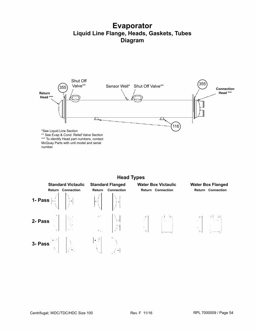
EvaporatorLiquid Line Flange, Heads, Gaskets, Tubes
Diagram
116
Sensor Well* Shut Off Valve**355355
1- Pass
2- Pass
3- Pass
Standard Victaulic Standard Flanged Water Box Victaulic Water Box FlangedReturn Connection ConnectionReturn Return Connection
Head Types
Shut Off Valve**
Return Connection
*See Liquid Line Section** See Evap & Cond. Relief Valve Section*** To identify Head part numbers, contact McQuay Parts with unit model and serial number.
ConnectionHead ***Return
Head ***
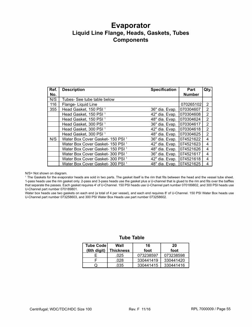
RPL 7000009 / Page 55Centrifugal; WDC/TDC/HDC Size 100 Rev. F 11/16
EvaporatorLiquid Line Flange, Heads, Gaskets, Tubes
Components
Tube Code Wall 16 20 (6th digit) Thickness foot foot E .025 073238597 073238598 F .028 330441419 330441420 Q .035 330441415 330441416
Tube Table
Ref. Description Specification Part Qty. No. Number N/S Tubes- See tube table below 116 Flange- Liquid Line 070265102 2 355 Head Gasket, 150 PSI 1 36" dia. Evap. 070304607 2 Head Gasket, 150 PSI 1 42" dia. Evap. 070304608 2 Head Gasket, 150 PSI 1 48" dia. Evap. 070304624 2 Head Gasket, 300 PSI 1 36" dia. Evap. 070304617 2 Head Gasket, 300 PSI 1 42" dia. Evap. 070304618 2 Head Gasket, 300 PSI 1 48" dia. Evap. 070304625 2 N/S Water Box Cover Gasket- 150 PSI 1 36" dia. Evap. 074521622 4 Water Box Cover Gasket- 150 PSI 1 42" dia. Evap. 074521623 4 Water Box Cover Gasket- 150 PSI 1 48" dia. Evap. 074521626 4 Water Box Cover Gasket- 300 PSI 1 36" dia. Evap. 074521617 4 Water Box Cover Gasket- 300 PSI 1 42" dia. Evap. 074521618 4 Water Box Cover Gasket- 300 PSI 1 48" dia. Evap. 074521625 4
N/S= Not shown on diagram. 1 The Gaskets for the evaporator heads are sold in two parts. The gasket itself is the rim that fits between the head and the vessel tube sheet. 1-pass heads use the rim gasket only. 2-pass and 3-pass heads use the gasket plus a U-channel that is glued to the rim and fits over the baffles that separate the passes. Each gasket requires 4' of U-Channel. 150 PSI heads use U-Channel part number 070189802, and 300 PSI heads use U-Channel part number 070189801. Water box heads use two gaskets on each end (a total of 4 per vessel), and each end requires 8' of U-Channel. 150 PSI Water Box heads use U-Channel part number 073258603, and 300 PSI Water Box Heads use part number 073258602.
RPL 7000009 / Page 56Centrifugal; WDC/TDC/HDC Size 100 Rev. F 11/16
5 1 A 01750 01
Plant Identification 5= Staunton
Serial NumberYear of Manufacture0= 20001= 20012= 20023= 20034= 20045= 2005
Month of ManufactureA= JanuaryB= FebruaryC= MarchD= AprilE= MayF= June
G= JulyH= AugustJ= SeptemberK= OctoberL= NovemberM= December
Serial Number- Compressor
Engineering Revision
CompressorNomenclature
Compressor
Model Number- Compressor
Motor Style Number
CE 100 M BK 85 R
Gear Ratio CodeSee Compressor Section Gear Table
The motor style number is the part number. See the following pages for list of motor, stator & rotor/shafts.
Impeller Size100= 10.0"
Impeller TypeL, M
Motor HorsepowerSee Compressor Section Motor Table
Motor VoltageSee Compressor Section Motor Table
0 923456010 F1R01
Unit G.O. No.F1R01 = Compressor #1J1R01 = Compressor #2
Style Number- Compressor
Always 0
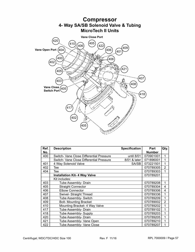
RPL 7000009 / Page 57Centrifugal; WDC/TDC/HDC Size 100 Rev. F 11/16
Ref. Description Specification Part Qty. No. Number 400 Switch- Vane Close Differential Pressure until 8/01 070901001 1 Switch- Vane Close Differential Pressure 8/01 & later 071896001 1 401 4 Way Solenoid Valve SA/SB 073221501 1 402 Tee 070789305 2 404 Tee 070789303 1 Installation Kit- 4 Way Valve 070789201 Kit includes: 403 Tube Assembly- Drain 070789208 1 405 Straight Connector 070789304 4 406 Elbow Connector 070789306 4 407 Swivel- Straight Thread 070789336 1 408 Tube Assembly- Switch 070789209 1 409 Bolt- Mounting Bracket 070789002 2 410 Mounting Bracket- 4 Way Valve 070789202 1 417 Tube Assembly- Drain 070789102 1 418 Tube Assembly- Supply 070789203 1 420 Tube Assembly- Drain 070789205 1 421 Tube Assembly- Vane Open 070789210 1 422 Tube Assembly- Vane Close 070789207 1
Compressor4- Way SA/SB Solenoid Valve & Tubing
MicroTech II Units
401
406
409
403
405
406
402
400402
417
422
405
418
408
421405
404
405
406410420
Vane Close Switch Port
Vane Close Port
Vane Open Port
407
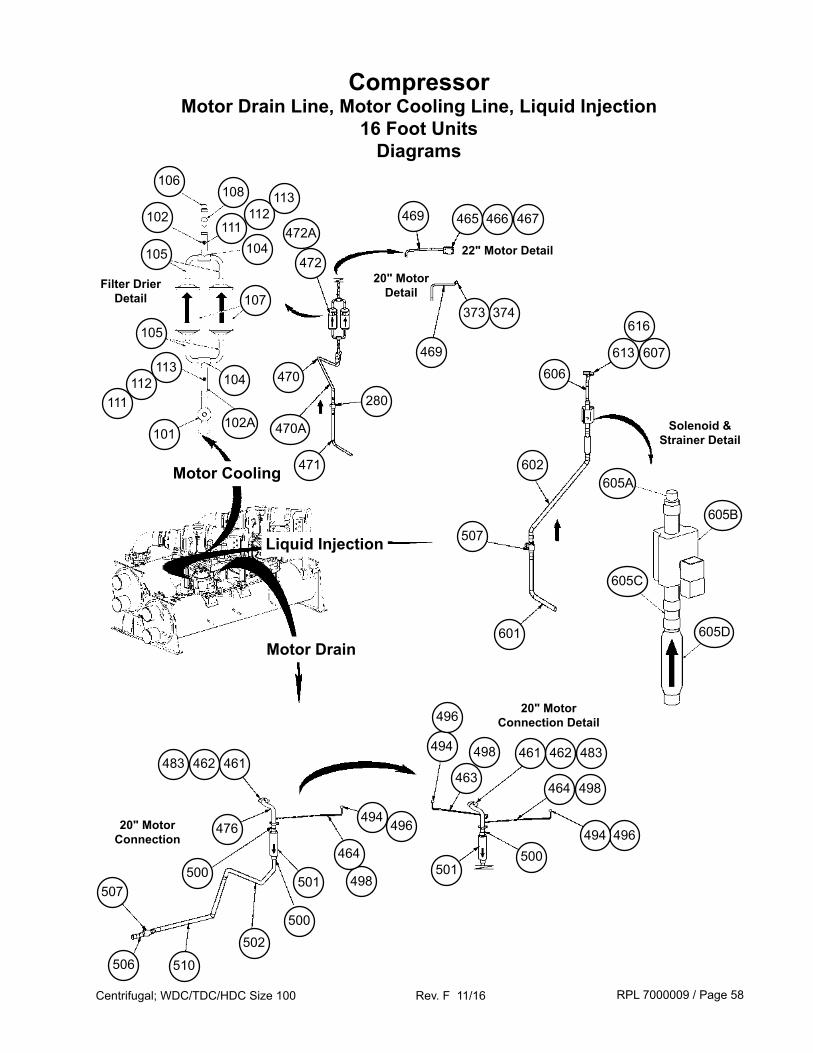
RPL 7000009 / Page 58Centrifugal; WDC/TDC/HDC Size 100 Rev. F 11/16
CompressorMotor Drain Line, Motor Cooling Line, Liquid Injection
16 Foot UnitsDiagrams
22" Motor Detail
Motor Cooling
Motor Drain
Liquid Injection
107
102A101
106108
105
105
102111
112
104
113
111112
113
104472
472A
470
471
280
470A
469 465 466 467
373 374
469
20" Motor Detail
Filter DrierDetail
Solenoid & Strainer Detail
613 607
616
606
602
507
601
605A
605B
605C
605D
507
506 510
500
476
461
502500
501
462483
496494
498
464496494
498464
494
496
483462461498
463
501500
20" Motor Connection
20" Motor Connection Detail
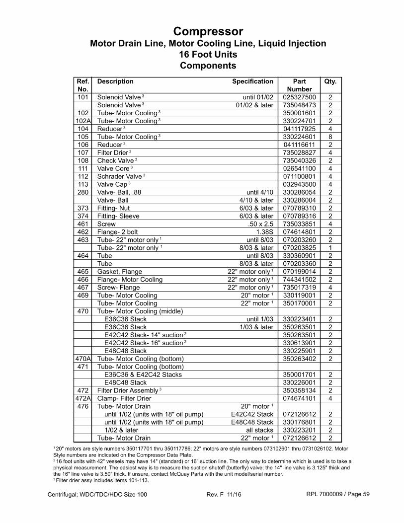
RPL 7000009 / Page 59Centrifugal; WDC/TDC/HDC Size 100 Rev. F 11/16
Ref. Description Specification Part Qty. No. Number 101 Solenoid Valve 3 until 01/02 025327500 2 Solenoid Valve 3 01/02 & later 735048473 2 102 Tube- Motor Cooling 3 350001601 2 102A Tube- Motor Cooling 3 330224701 2 104 Reducer 3 041117925 4 105 Tube- Motor Cooling 3 330224601 8 106 Reducer 3 041116611 2 107 Filter Drier 3 735028827 4 108 Check Valve 3 735040326 2 111 Valve Core 3 026541100 4 112 Schrader Valve 3 071100801 4 113 Valve Cap 3 032943500 4 280 Valve- Ball, .88 until 4/10 330286054 2 Valve- Ball 4/10 & later 330286004 2 373 Fitting- Nut 6/03 & later 070789310 2 374 Fitting- Sleeve 6/03 & later 070789316 2 461 Screw .50 x 2.5 735033851 4 462 Flange- 2 bolt 1.38S 074614801 2 463 Tube- 22" motor only 1 until 8/03 070203260 2 Tube- 22" motor only 1 8/03 & later 070203825 1 464 Tube until 8/03 330360901 2 Tube 8/03 & later 070203360 2 465 Gasket, Flange 22" motor only 1 070199014 2 466 Flange- Motor Cooling 22" motor only 1 744341502 2 467 Screw- Flange 22" motor only 1 735017319 4 469 Tube- Motor Cooling 20" motor 1 330119001 2 Tube- Motor Cooling 22" motor 1 350170001 2 470 Tube- Motor Cooling (middle) E36C36 Stack until 1/03 330223401 2 E36C36 Stack 1/03 & later 350263501 2 E42C42 Stack- 14" suction 2 350263501 2 E42C42 Stack- 16" suction 2 330613901 2 E48C48 Stack 330225901 2 470A Tube- Motor Cooling (bottom) 350263402 2 471 Tube- Motor Cooling (bottom) E36C36 & E42C42 Stacks 350001701 2 E48C48 Stack 330226001 2 472 Filter Drier Assembly 3 350358134 2 472A Clamp- Filter Drier 074674101 4 476 Tube- Motor Drain 20" motor 1 until 1/02 (units with 18" oil pump) E42C42 Stack 072126612 2 until 1/02 (units with 18" oil pump) E48C48 Stack 330176801 2 1/02 & later all stacks 330223201 2 Tube- Motor Drain 22" motor 1 072126612 2
1 20" motors are style numbers 350117701 thru 350117786; 22" motors are style numbers 073102601 thru 0731026102. Motor Style numbers are indicated on the Compressor Data Plate.2 16 foot units with 42" vessels may have 14" (standard) or 16" suction line. The only way to determine which is used is to take a physical measurement. The easiest way is to measure the suction shutoff (butterfly) valve; the 14" line valve is 3.125" thick and the 16" line valve is 3.50" thick. If unsure, contact McQuay Parts with the unit model/serial number.3 Filter drier assy includes items 101-113.
CompressorMotor Drain Line, Motor Cooling Line, Liquid Injection
16 Foot UnitsComponents
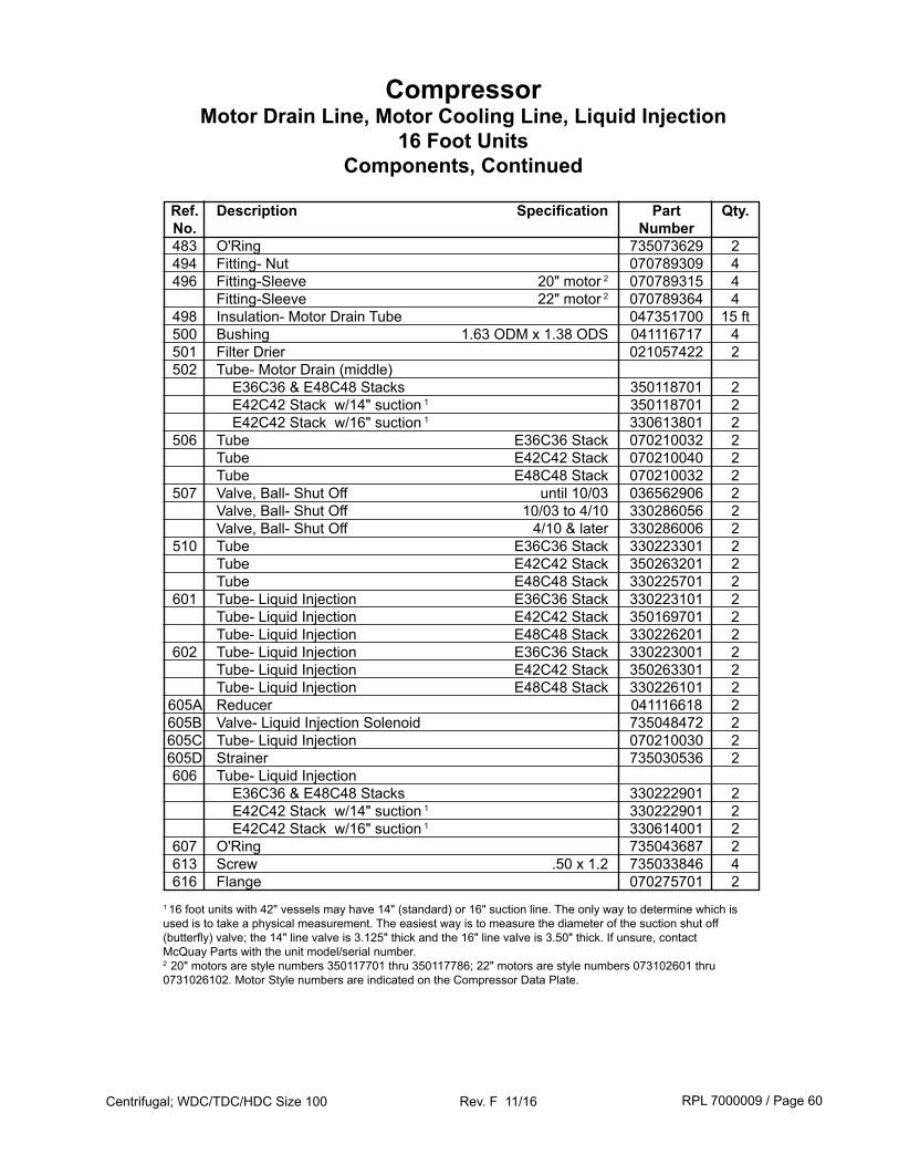
RPL 7000009 / Page 60Centrifugal; WDC/TDC/HDC Size 100 Rev. F 11/16
Ref. Description Specification Part Qty. No. Number 483 O'Ring 735073629 2 494 Fitting- Nut 070789309 4 496 Fitting-Sleeve 20" motor 2 070789315 4 Fitting-Sleeve 22" motor 2 070789364 4 498 Insulation- Motor Drain Tube 047351700 15 ft 500 Bushing 1.63 ODM x 1.38 ODS 041116717 4 501 Filter Drier 021057422 2 502 Tube- Motor Drain (middle) E36C36 & E48C48 Stacks 350118701 2 E42C42 Stack w/14" suction 1 350118701 2 E42C42 Stack w/16" suction 1 330613801 2 506 Tube E36C36 Stack 070210032 2 Tube E42C42 Stack 070210040 2 Tube E48C48 Stack 070210032 2 507 Valve, Ball- Shut Off until 10/03 036562906 2 Valve, Ball- Shut Off 10/03 to 4/10 330286056 2 Valve, Ball- Shut Off 4/10 & later 330286006 2 510 Tube E36C36 Stack 330223301 2 Tube E42C42 Stack 350263201 2 Tube E48C48 Stack 330225701 2 601 Tube- Liquid Injection E36C36 Stack 330223101 2 Tube- Liquid Injection E42C42 Stack 350169701 2 Tube- Liquid Injection E48C48 Stack 330226201 2 602 Tube- Liquid Injection E36C36 Stack 330223001 2 Tube- Liquid Injection E42C42 Stack 350263301 2 Tube- Liquid Injection E48C48 Stack 330226101 2 605A Reducer 041116618 2 605B Valve- Liquid Injection Solenoid 735048472 2 605C Tube- Liquid Injection 070210030 2 605D Strainer 735030536 2 606 Tube- Liquid Injection E36C36 & E48C48 Stacks 330222901 2 E42C42 Stack w/14" suction 1 330222901 2 E42C42 Stack w/16" suction 1 330614001 2 607 O'Ring 735043687 2 613 Screw .50 x 1.2 735033846 4 616 Flange 070275701 2
CompressorMotor Drain Line, Motor Cooling Line, Liquid Injection
16 Foot UnitsComponents, Continued
1 16 foot units with 42" vessels may have 14" (standard) or 16" suction line. The only way to determine which is used is to take a physical measurement. The easiest way is to measure the diameter of the suction shut off (butterfly) valve; the 14" line valve is 3.125" thick and the 16" line valve is 3.50" thick. If unsure, contact McQuay Parts with the unit model/serial number.2 20" motors are style numbers 350117701 thru 350117786; 22" motors are style numbers 073102601 thru 0731026102. Motor Style numbers are indicated on the Compressor Data Plate.
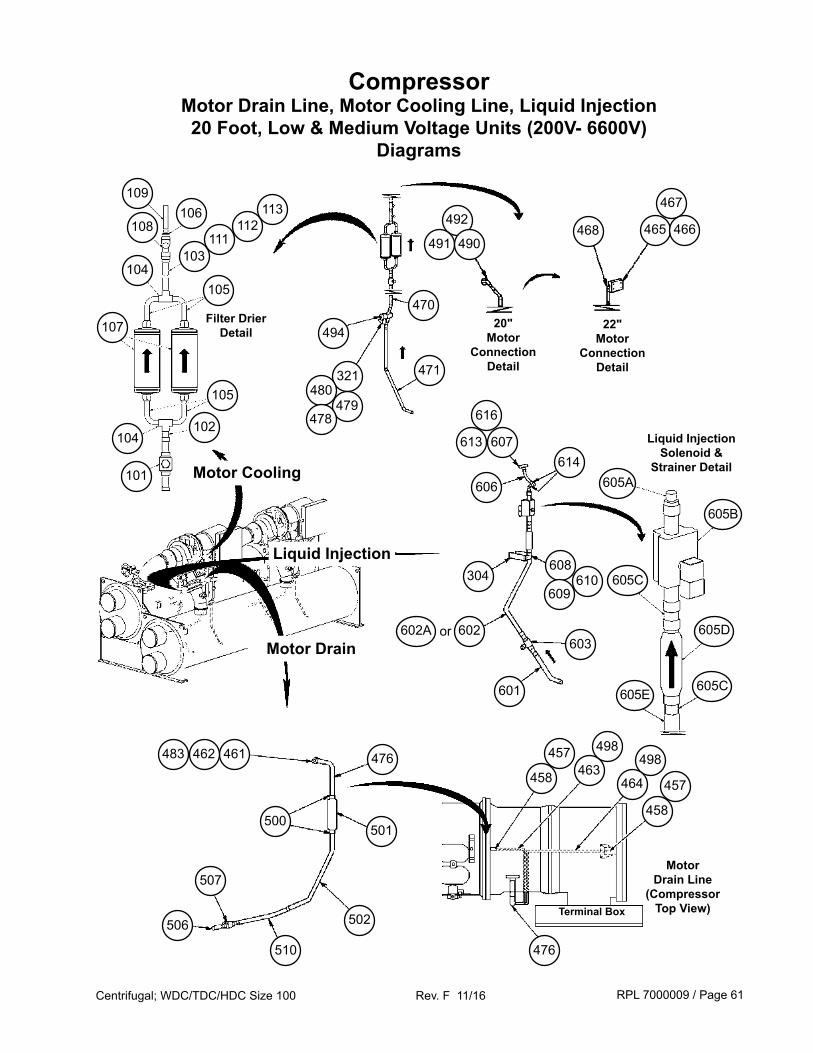
RPL 7000009 / Page 61Centrifugal; WDC/TDC/HDC Size 100 Rev. F 11/16
CompressorMotor Drain Line, Motor Cooling Line, Liquid Injection20 Foot, Low & Medium Voltage Units (200V- 6600V)
Diagrams
22" Motor
ConnectionDetail
Motor Cooling
Motor Drain
Liquid Injection
107
101
106108
105
104
103111
112
104
113
102
471
470
494
321
492
491 490
467
465 466468
20" Motor
Connection Detail
Filter DrierDetail
Liquid InjectionSolenoid &
Strainer Detail
613 607
616
614
603
601
605A
605B
605C
605D
507
506
510
500
461
502
476
501
462483 457
458498
464
Motor Drain Line
(Compressor Top View)
457
458
476
498
463
Terminal Box
602602A or
608610
609304
109
105
605E605C
606
480479
478
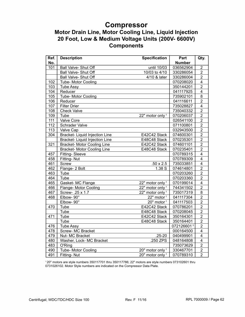
RPL 7000009 / Page 62Centrifugal; WDC/TDC/HDC Size 100 Rev. F 11/16
Ref. Description Specification Part Qty. No. Number 101 Ball Valve- Shut Off until 10/03 036562904 2 Ball Valve- Shut Off 10/03 to 4/10 330286054 2 Ball Valve- Shut Off 4/10 & later 330286004 2 102 Tube- Motor Cooling 070208020 4 103 Tube Assy 350144201 2 104 Reducer 041117925 4 105 Tube- Motor Cooling 735902101 8 106 Reducer 041116611 2 107 Filter Drier 735028827 4 108 Check Valve 735040332 2 109 Tube 22" motor only 1 070206037 2 111 Valve Core 026541100 2 112 Schrader Valve 071100801 2 113 Valve Cap 032943500 2 304 Bracket- Liquid Injection Line E42C42 Stack 074600301 2 Bracket- Liquid Injection Line E48C48 Stack 070235301 2 321 Bracket- Motor Cooling Line E42C42 Stack 074601101 2 Bracket- Motor Cooling Line E48C48 Stack 070235401 2 457 Fitting- Sleeve 070789315 4 458 Fitting- Nut 070789309 4 461 Screw .50 x 2.5 735033851 4 462 Flange- 2 Bolt 1.38 S 074614801 2 463 Tube 070203260 2 464 Tube 070203360 2 465 Gasket- MC Flange 22" motor only 1 070199014 4 466 Flange- Motor Cooling 22" motor only 1 744341502 2 467 Screw- .25 x 1.7 22" motor only 1 735017319 8 468 Elbow- 90° 22" motor 1 041117304 2 Elbow- 90° 20" motor 1 041117503 2 470 Tube E42C42 Stack 070786201 2 Tube E48C48 Stack 070208045 2 471 Tube E42C42 Stack 350164301 2 Tube E48C48 Stack 350164401 2 476 Tube Assy 072126601 3 2 478 Screw- MC Bracket 000164500 4 479 Nut- MC Bracket .25-20 040499901 4 480 Washer, Lock- MC Bracket .250 ZPS 048164808 4 483 O'Ring 735073629 2 490 Tube- Motor Cooling 20" motor only 1 330467701 2 491 Fitting- Nut 20" motor only 1 070789310 21 20" motors are style numbers 350117701 thru 350117786; 22" motors are style numbers 073102601 thru 0731026102. Motor Style numbers are indicated on the Compressor Data Plate.
CompressorMotor Drain Line, Motor Cooling Line, Liquid Injection20 Foot, Low & Medium Voltage Units (200V- 6600V)
Components
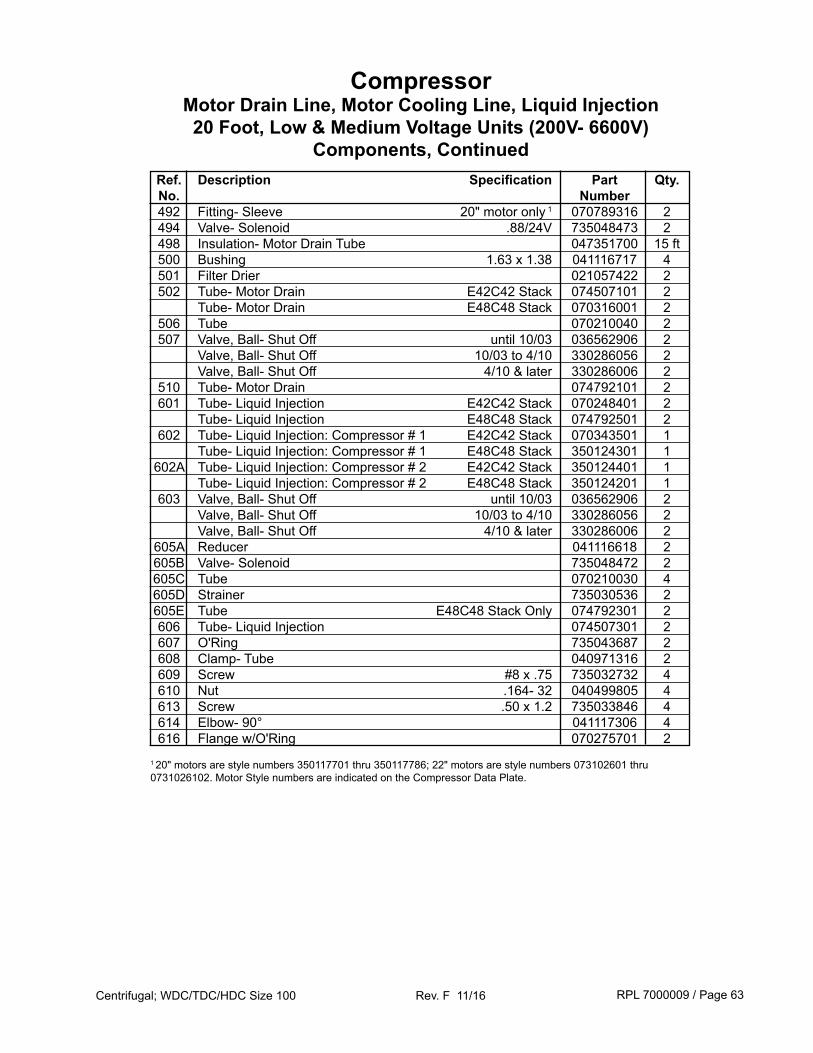
RPL 7000009 / Page 63Centrifugal; WDC/TDC/HDC Size 100 Rev. F 11/16
Ref. Description Specification Part Qty. No. Number 492 Fitting- Sleeve 20" motor only 1 070789316 2 494 Valve- Solenoid .88/24V 735048473 2 498 Insulation- Motor Drain Tube 047351700 15 ft 500 Bushing 1.63 x 1.38 041116717 4 501 Filter Drier 021057422 2 502 Tube- Motor Drain E42C42 Stack 074507101 2 Tube- Motor Drain E48C48 Stack 070316001 2 506 Tube 070210040 2 507 Valve, Ball- Shut Off until 10/03 036562906 2 Valve, Ball- Shut Off 10/03 to 4/10 330286056 2 Valve, Ball- Shut Off 4/10 & later 330286006 2 510 Tube- Motor Drain 074792101 2 601 Tube- Liquid Injection E42C42 Stack 070248401 2 Tube- Liquid Injection E48C48 Stack 074792501 2 602 Tube- Liquid Injection: Compressor # 1 E42C42 Stack 070343501 1 Tube- Liquid Injection: Compressor # 1 E48C48 Stack 350124301 1 602A Tube- Liquid Injection: Compressor # 2 E42C42 Stack 350124401 1 Tube- Liquid Injection: Compressor # 2 E48C48 Stack 350124201 1 603 Valve, Ball- Shut Off until 10/03 036562906 2 Valve, Ball- Shut Off 10/03 to 4/10 330286056 2 Valve, Ball- Shut Off 4/10 & later 330286006 2 605A Reducer 041116618 2 605B Valve- Solenoid 735048472 2 605C Tube 070210030 4 605D Strainer 735030536 2 605E Tube E48C48 Stack Only 074792301 2 606 Tube- Liquid Injection 074507301 2 607 O'Ring 735043687 2 608 Clamp- Tube 040971316 2 609 Screw #8 x .75 735032732 4 610 Nut .164- 32 040499805 4 613 Screw .50 x 1.2 735033846 4 614 Elbow- 90° 041117306 4 616 Flange w/O'Ring 070275701 2
CompressorMotor Drain Line, Motor Cooling Line, Liquid Injection20 Foot, Low & Medium Voltage Units (200V- 6600V)
Components, Continued
1 20" motors are style numbers 350117701 thru 350117786; 22" motors are style numbers 073102601 thru 0731026102. Motor Style numbers are indicated on the Compressor Data Plate.
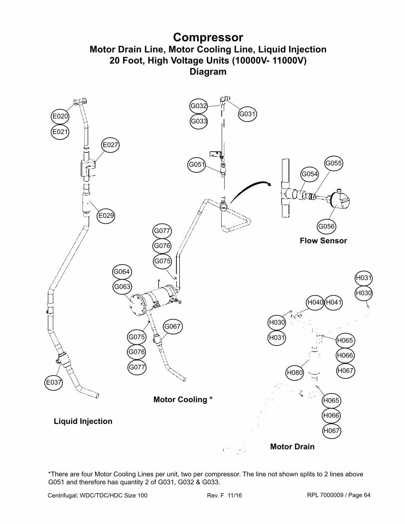
RPL 7000009 / Page 64Centrifugal; WDC/TDC/HDC Size 100 Rev. F 11/16
CompressorMotor Drain Line, Motor Cooling Line, Liquid Injection
20 Foot, High Voltage Units (10000V- 11000V)Diagram
Motor Cooling *
Motor Drain
Liquid Injection
E027
E029
E020
E021
E037
G054
G056
G055
G067
G063
G064
G051
H030
G032
H040 H041
H065
H066
H067
G031G033
H031 H065
H066
H067
H031
H030
G075
G076
G077
G077
G076
G075
Flow Sensor
*There are four Motor Cooling Lines per unit, two per compressor. The line not shown splits to 2 lines above G051 and therefore has quantity 2 of G031, G032 & G033.
H080
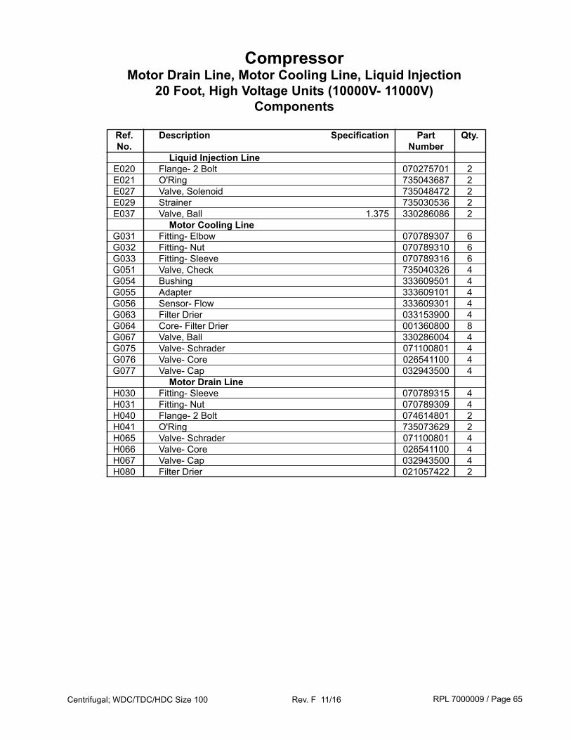
RPL 7000009 / Page 65Centrifugal; WDC/TDC/HDC Size 100 Rev. F 11/16
Ref. Description Specification Part Qty. No. Number Liquid Injection Line E020 Flange- 2 Bolt 070275701 2 E021 O'Ring 735043687 2 E027 Valve, Solenoid 735048472 2 E029 Strainer 735030536 2 E037 Valve, Ball 1.375 330286086 2 Motor Cooling Line G031 Fitting- Elbow 070789307 6 G032 Fitting- Nut 070789310 6 G033 Fitting- Sleeve 070789316 6 G051 Valve, Check 735040326 4 G054 Bushing 333609501 4 G055 Adapter 333609101 4 G056 Sensor- Flow 333609301 4 G063 Filter Drier 033153900 4 G064 Core- Filter Drier 001360800 8 G067 Valve, Ball 330286004 4 G075 Valve- Schrader 071100801 4 G076 Valve- Core 026541100 4 G077 Valve- Cap 032943500 4 Motor Drain Line H030 Fitting- Sleeve 070789315 4 H031 Fitting- Nut 070789309 4 H040 Flange- 2 Bolt 074614801 2 H041 O'Ring 735073629 2 H065 Valve- Schrader 071100801 4 H066 Valve- Core 026541100 4 H067 Valve- Cap 032943500 4 H080 Filter Drier 021057422 2
CompressorMotor Drain Line, Motor Cooling Line, Liquid Injection
20 Foot, High Voltage Units (10000V- 11000V)Components
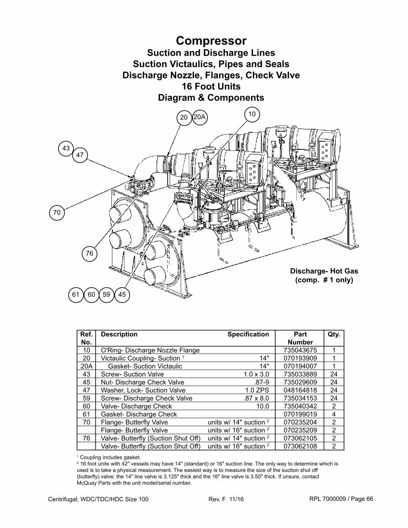
RPL 7000009 / Page 66Centrifugal; WDC/TDC/HDC Size 100 Rev. F 11/16
CompressorSuction and Discharge Lines
Suction Victaulics, Pipes and Seals Discharge Nozzle, Flanges, Check Valve
16 Foot Units Diagram & Components
Ref. Description Specification Part Qty. No. Number 10 O'Ring- Discharge Nozzle Flange 735043675 1 20 Victaulic Coupling- Suction 1 14" 070193909 1 20A Gasket- Suction Victaulic 14" 070194007 1 43 Screw- Suction Valve 1.0 x 3.0 735033889 24 45 Nut- Discharge Check Valve .87-9 735029609 24 47 Washer, Lock- Suction Valve 1.0 ZPS 048164818 24 59 Screw- Discharge Check Valve .87 x 8.0 735034153 24 60 Valve- Discharge Check 10.0 735040342 2 61 Gasket- Discharge Check 070199019 4 70 Flange- Butterfly Valve units w/ 14" suction 2 070235204 2 Flange- Butterfly Valve units w/ 16" suction 2 070235209 2 76 Valve- Butterfly (Suction Shut Off) units w/ 14" suction 2 073062105 2 Valve- Butterfly (Suction Shut Off) units w/ 16" suction 2 073062108 21 Coupling includes gasket.2 16 foot units with 42" vessels may have 14" (standard) or 16" suction line. The only way to determine which is used is to take a physical measurement. The easiest way is to measure the size of the suction shut off (butterfly) valve; the 14" line valve is 3.125" thick and the 16" line valve is 3.50" thick. If unsure, contact McQuay Parts with the unit model/serial number.
70
76
47
20
43
45
20A
596061
Discharge- Hot Gas(comp. # 1 only)
10
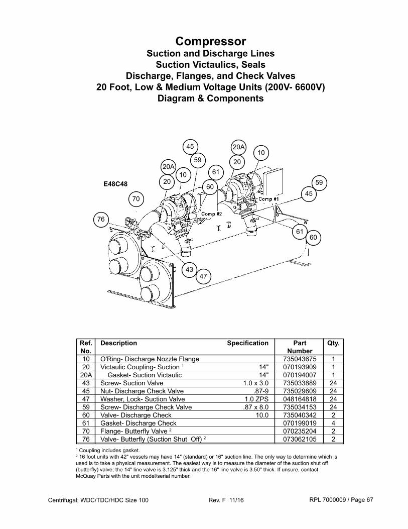
RPL 7000009 / Page 67Centrifugal; WDC/TDC/HDC Size 100 Rev. F 11/16
CompressorSuction and Discharge Lines
Suction Victaulics, Seals Discharge, Flanges, and Check Valves
20 Foot, Low & Medium Voltage Units (200V- 6600V) Diagram & Components
Ref. Description Specification Part Qty. No. Number 10 O'Ring- Discharge Nozzle Flange 735043675 1 20 Victaulic Coupling- Suction 1 14" 070193909 1 20A Gasket- Suction Victaulic 14" 070194007 1 43 Screw- Suction Valve 1.0 x 3.0 735033889 24 45 Nut- Discharge Check Valve .87-9 735029609 24 47 Washer, Lock- Suction Valve 1.0 ZPS 048164818 24 59 Screw- Discharge Check Valve .87 x 8.0 735034153 24 60 Valve- Discharge Check 10.0 735040342 2 61 Gasket- Discharge Check 070199019 4 70 Flange- Butterfly Valve 2 070235204 2 76 Valve- Butterfly (Suction Shut Off) 2 073062105 2
70
47
20
43
6120A
60
76
1045
59
10E48C48
20
20A
4559
6160
1 Coupling includes gasket. 2 16 foot units with 42" vessels may have 14" (standard) or 16" suction line. The only way to determine which is used is to take a physical measurement. The easiest way is to measure the diameter of the suction shut off (butterfly) valve; the 14" line valve is 3.125" thick and the 16" line valve is 3.50" thick. If unsure, contact McQuay Parts with the unit model/serial number.
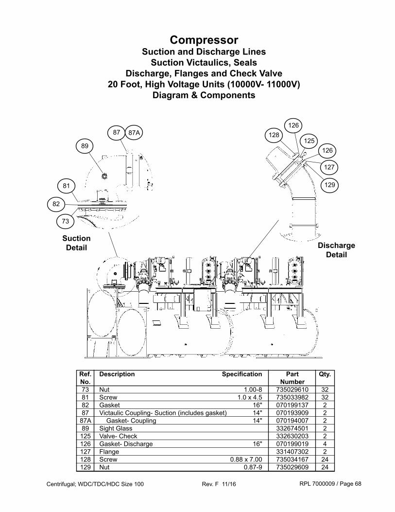
RPL 7000009 / Page 68Centrifugal; WDC/TDC/HDC Size 100 Rev. F 11/16
CompressorSuction and Discharge Lines
Suction Victaulics, Seals Discharge, Flanges and Check Valve
20 Foot, High Voltage Units (10000V- 11000V) Diagram & Components
Ref. Description Specification Part Qty. No. Number 73 Nut 1.00-8 735029610 32 81 Screw 1.0 x 4.5 735033982 32 82 Gasket 16" 070199137 2 87 Victaulic Coupling- Suction (includes gasket) 14" 070193909 2 87A Gasket- Coupling 14" 070194007 2 89 Sight Glass 332674501 2 125 Valve- Check 332630203 2 126 Gasket- Discharge 16" 070199019 4 127 Flange 331407302 2 128 Screw 0.88 x 7.00 735034167 24 129 Nut 0.87-9 735029609 24
87
89
81
82
73
128126
125126
127
129
SuctionDetail Discharge
Detail
87A
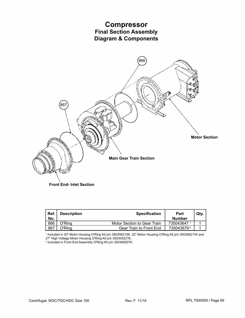
RPL 7000009 / Page 69Centrifugal; WDC/TDC/HDC Size 100 Rev. F 11/16
CompressorFinal Section AssemblyDiagram & Components
Ref. Description Specification Part Qty. No. Number 866 O'Ring Motor Section to Gear Train 735043647 1 1 867 O'Ring Gear Train to Front End 735043679 2 11 Included in 20" Motor Housing O'Ring Kit p/n 350306210K, 22" Motor Housing O'Ring Kit p/n 350306211K and 27" High Voltage Motor Housing O'Ring Kit p/n 350305221K.2 Included in Front End Assembly O'Ring Kit p/n 350306207K.
Front End- Inlet Section
867
866
Motor Section
Main Gear Train Section
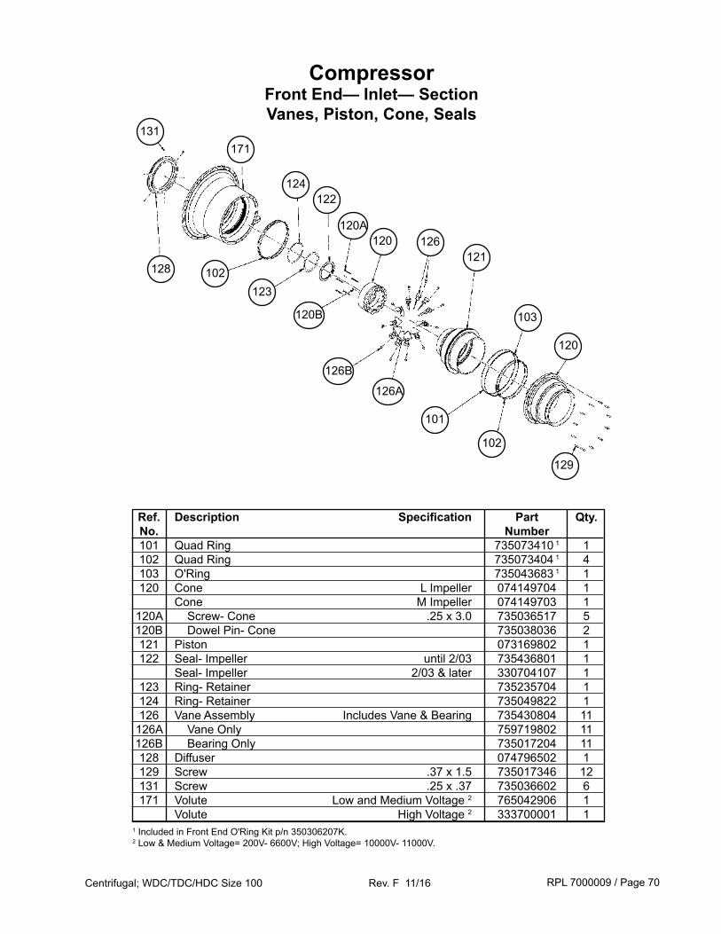
RPL 7000009 / Page 70Centrifugal; WDC/TDC/HDC Size 100 Rev. F 11/16
CompressorFront End— Inlet— SectionVanes, Piston, Cone, Seals
128
Ref. Description Specification Part Qty. No. Number 101 Quad Ring 735073410 1 1 102 Quad Ring 735073404 1 4 103 O'Ring 735043683 1 1 120 Cone L Impeller 074149704 1 Cone M Impeller 074149703 1 120A Screw- Cone .25 x 3.0 735036517 5 120B Dowel Pin- Cone 735038036 2 121 Piston 073169802 1 122 Seal- Impeller until 2/03 735436801 1 Seal- Impeller 2/03 & later 330704107 1 123 Ring- Retainer 735235704 1 124 Ring- Retainer 735049822 1 126 Vane Assembly Includes Vane & Bearing 735430804 11 126A Vane Only 759719802 11 126B Bearing Only 735017204 11 128 Diffuser 074796502 1 129 Screw .37 x 1.5 735017346 12 131 Screw .25 x .37 735036602 6 171 Volute Low and Medium Voltage 2 765042906 1 Volute High Voltage 2 333700001 11 Included in Front End O'Ring Kit p/n 350306207K.2 Low & Medium Voltage= 200V- 6600V; High Voltage= 10000V- 11000V.
131
124
126
102
122
123
120
120
129
126B
103
121
171
126A
102
101
120B
120A
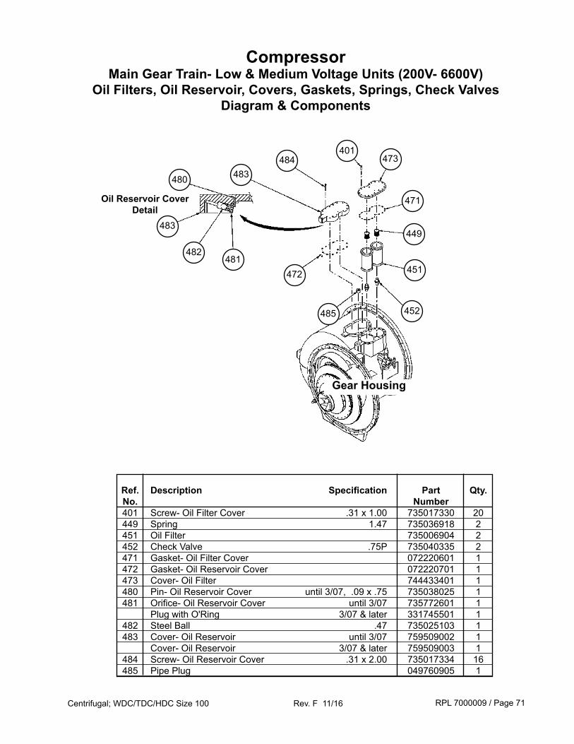
RPL 7000009 / Page 71Centrifugal; WDC/TDC/HDC Size 100 Rev. F 11/16
CompressorMain Gear Train- Low & Medium Voltage Units (200V- 6600V)
Oil Filters, Oil Reservoir, Covers, Gaskets, Springs, Check ValvesDiagram & Components
451
449
471
452485
472
401473
Ref. Description Specification Part Qty. No. Number 401 Screw- Oil Filter Cover .31 x 1.00 735017330 20 449 Spring 1.47 735036918 2 451 Oil Filter 735006904 2 452 Check Valve .75P 735040335 2 471 Gasket- Oil Filter Cover 072220601 1 472 Gasket- Oil Reservoir Cover 072220701 1 473 Cover- Oil Filter 744433401 1 480 Pin- Oil Reservoir Cover until 3/07, .09 x .75 735038025 1 481 Orifice- Oil Reservoir Cover until 3/07 735772601 1 Plug with O'Ring 3/07 & later 331745501 1 482 Steel Ball .47 735025103 1 483 Cover- Oil Reservoir until 3/07 759509002 1 Cover- Oil Reservoir 3/07 & later 759509003 1 484 Screw- Oil Reservoir Cover .31 x 2.00 735017334 16 485 Pipe Plug 049760905 1
484483480
483
482481
Gear Housing
Oil Reservoir Cover Detail
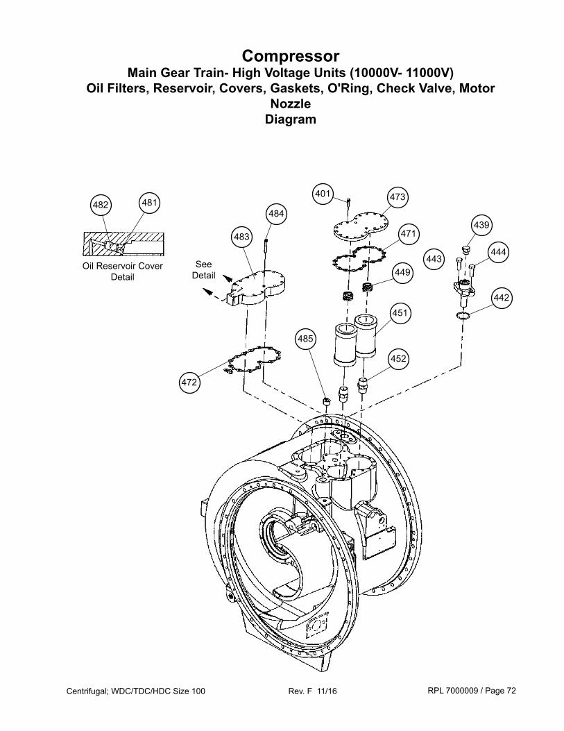
RPL 7000009 / Page 72Centrifugal; WDC/TDC/HDC Size 100 Rev. F 11/16
CompressorMain Gear Train- High Voltage Units (10000V- 11000V)
Oil Filters, Reservoir, Covers, Gaskets, O'Ring, Check Valve, Motor Nozzle
Diagram
451
449
471
452
485
472
401
439484
442
483
482 481
Oil Reservoir Cover Detail
443444
473
SeeDetail
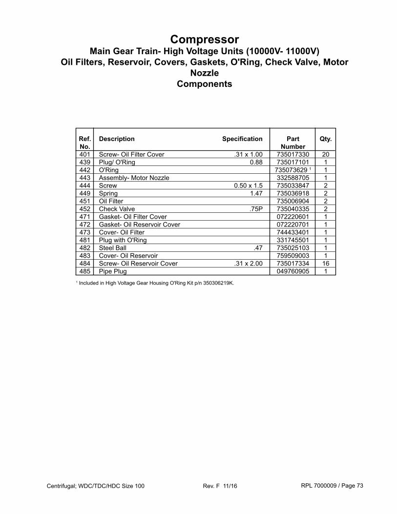
RPL 7000009 / Page 73Centrifugal; WDC/TDC/HDC Size 100 Rev. F 11/16
CompressorMain Gear Train- High Voltage Units (10000V- 11000V)
Oil Filters, Reservoir, Covers, Gaskets, O'Ring, Check Valve, Motor Nozzle
Components
Ref. Description Specification Part Qty. No. Number 401 Screw- Oil Filter Cover .31 x 1.00 735017330 20 439 Plug/ O'Ring 0.88 735017101 1 442 O'Ring 735073629 1 1 443 Assembly- Motor Nozzle 332588705 1 444 Screw 0.50 x 1.5 735033847 2 449 Spring 1.47 735036918 2 451 Oil Filter 735006904 2 452 Check Valve .75P 735040335 2 471 Gasket- Oil Filter Cover 072220601 1 472 Gasket- Oil Reservoir Cover 072220701 1 473 Cover- Oil Filter 744433401 1 481 Plug with O'Ring 331745501 1 482 Steel Ball .47 735025103 1 483 Cover- Oil Reservoir 759509003 1 484 Screw- Oil Reservoir Cover .31 x 2.00 735017334 16 485 Pipe Plug 049760905 11 Included in High Voltage Gear Housing O'Ring Kit p/n 350306219K.
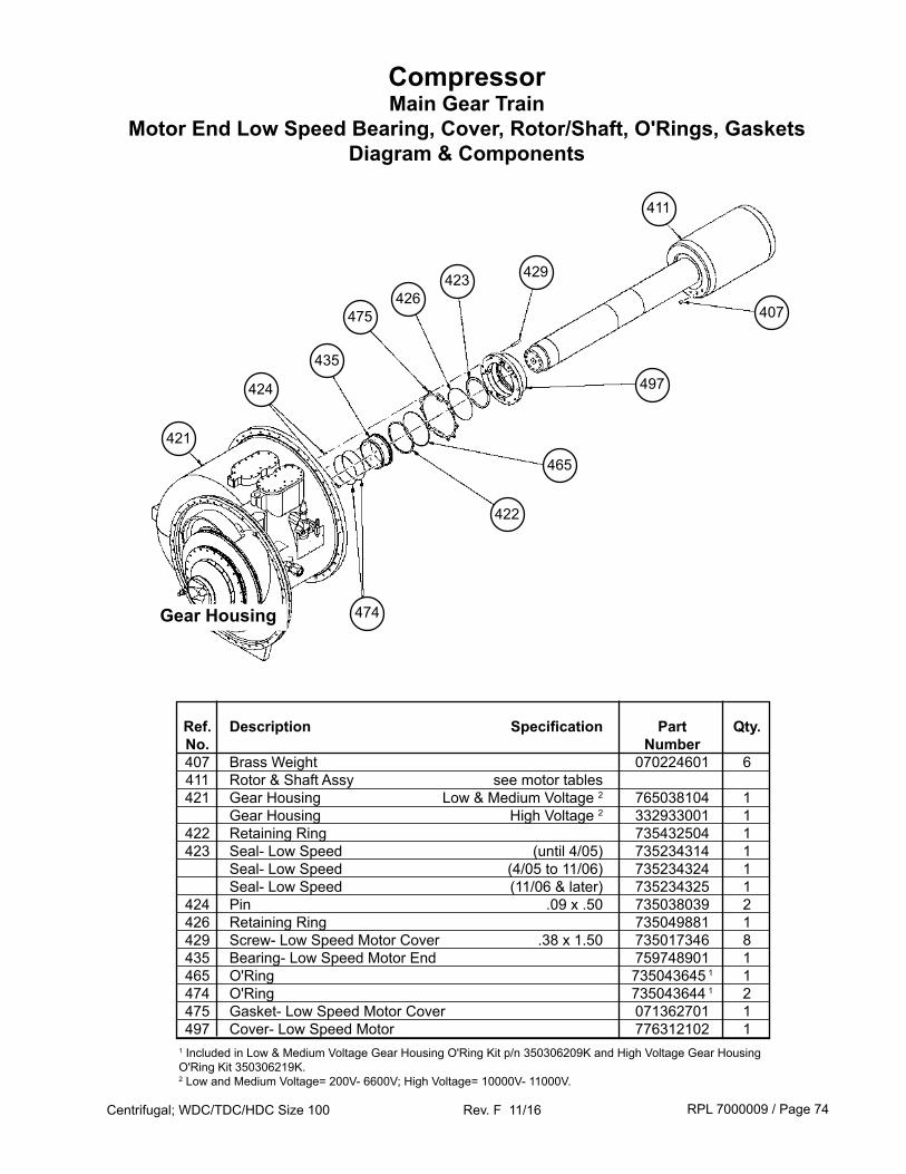
RPL 7000009 / Page 74Centrifugal; WDC/TDC/HDC Size 100 Rev. F 11/16
CompressorMain Gear Train
Motor End Low Speed Bearing, Cover, Rotor/Shaft, O'Rings, GasketsDiagram & Components
429
497
407
422
474
424
411
423426
475
421
435
465
Ref. Description Specification Part Qty. No. Number 407 Brass Weight 070224601 6 411 Rotor & Shaft Assy see motor tables 421 Gear Housing Low & Medium Voltage 2 765038104 1 Gear Housing High Voltage 2 332933001 1 422 Retaining Ring 735432504 1 423 Seal- Low Speed (until 4/05) 735234314 1 Seal- Low Speed (4/05 to 11/06) 735234324 1 Seal- Low Speed (11/06 & later) 735234325 1 424 Pin .09 x .50 735038039 2 426 Retaining Ring 735049881 1 429 Screw- Low Speed Motor Cover .38 x 1.50 735017346 8 435 Bearing- Low Speed Motor End 759748901 1 465 O'Ring 735043645 1 1 474 O'Ring 735043644 1 2 475 Gasket- Low Speed Motor Cover 071362701 1 497 Cover- Low Speed Motor 776312102 11 Included in Low & Medium Voltage Gear Housing O'Ring Kit p/n 350306209K and High Voltage Gear Housing O'Ring Kit 350306219K.2 Low and Medium Voltage= 200V- 6600V; High Voltage= 10000V- 11000V.
Gear Housing
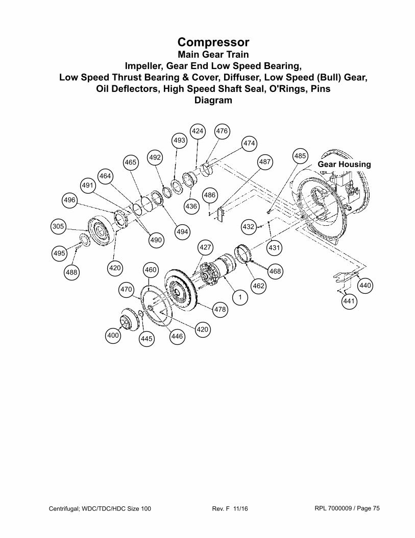
RPL 7000009 / Page 75Centrifugal; WDC/TDC/HDC Size 100 Rev. F 11/16
CompressorMain Gear Train
Impeller, Gear End Low Speed Bearing, Low Speed Thrust Bearing & Cover, Diffuser, Low Speed (Bull) Gear,
Oil Deflectors, High Speed Shaft Seal, O'Rings, PinsDiagram
465
493
436
487
431495
492
464491
496
488
305
474
Gear Housing 485
486
468
494490
420
462
446
460
470
400420
445
478
427
1
432
441
440
424 476
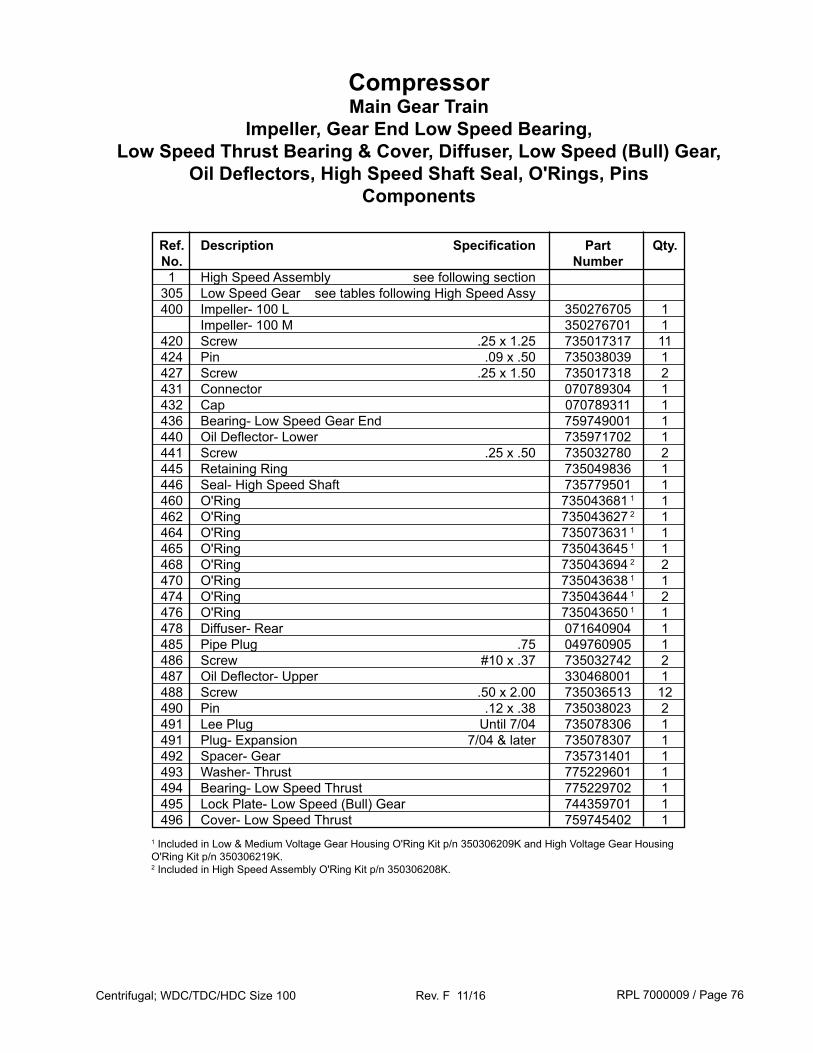
RPL 7000009 / Page 76Centrifugal; WDC/TDC/HDC Size 100 Rev. F 11/16
CompressorMain Gear Train
Impeller, Gear End Low Speed Bearing, Low Speed Thrust Bearing & Cover, Diffuser, Low Speed (Bull) Gear,
Oil Deflectors, High Speed Shaft Seal, O'Rings, PinsComponents
Ref. Description Specification Part Qty. No. Number 1 High Speed Assembly see following section 305 Low Speed Gear see tables following High Speed Assy 400 Impeller- 100 L 350276705 1 Impeller- 100 M 350276701 1 420 Screw .25 x 1.25 735017317 11 424 Pin .09 x .50 735038039 1 427 Screw .25 x 1.50 735017318 2 431 Connector 070789304 1 432 Cap 070789311 1 436 Bearing- Low Speed Gear End 759749001 1 440 Oil Deflector- Lower 735971702 1 441 Screw .25 x .50 735032780 2 445 Retaining Ring 735049836 1 446 Seal- High Speed Shaft 735779501 1 460 O'Ring 735043681 1 1 462 O'Ring 735043627 2 1 464 O'Ring 735073631 1 1 465 O'Ring 735043645 1 1 468 O'Ring 735043694 2 2 470 O'Ring 735043638 1 1 474 O'Ring 735043644 1 2 476 O'Ring 735043650 1 1 478 Diffuser- Rear 071640904 1 485 Pipe Plug .75 049760905 1 486 Screw #10 x .37 735032742 2 487 Oil Deflector- Upper 330468001 1 488 Screw .50 x 2.00 735036513 12 490 Pin .12 x .38 735038023 2 491 Lee Plug Until 7/04 735078306 1 491 Plug- Expansion 7/04 & later 735078307 1 492 Spacer- Gear 735731401 1 493 Washer- Thrust 775229601 1 494 Bearing- Low Speed Thrust 775229702 1 495 Lock Plate- Low Speed (Bull) Gear 744359701 1 496 Cover- Low Speed Thrust 759745402 11 Included in Low & Medium Voltage Gear Housing O'Ring Kit p/n 350306209K and High Voltage Gear Housing O'Ring Kit p/n 350306219K.2 Included in High Speed Assembly O'Ring Kit p/n 350306208K.
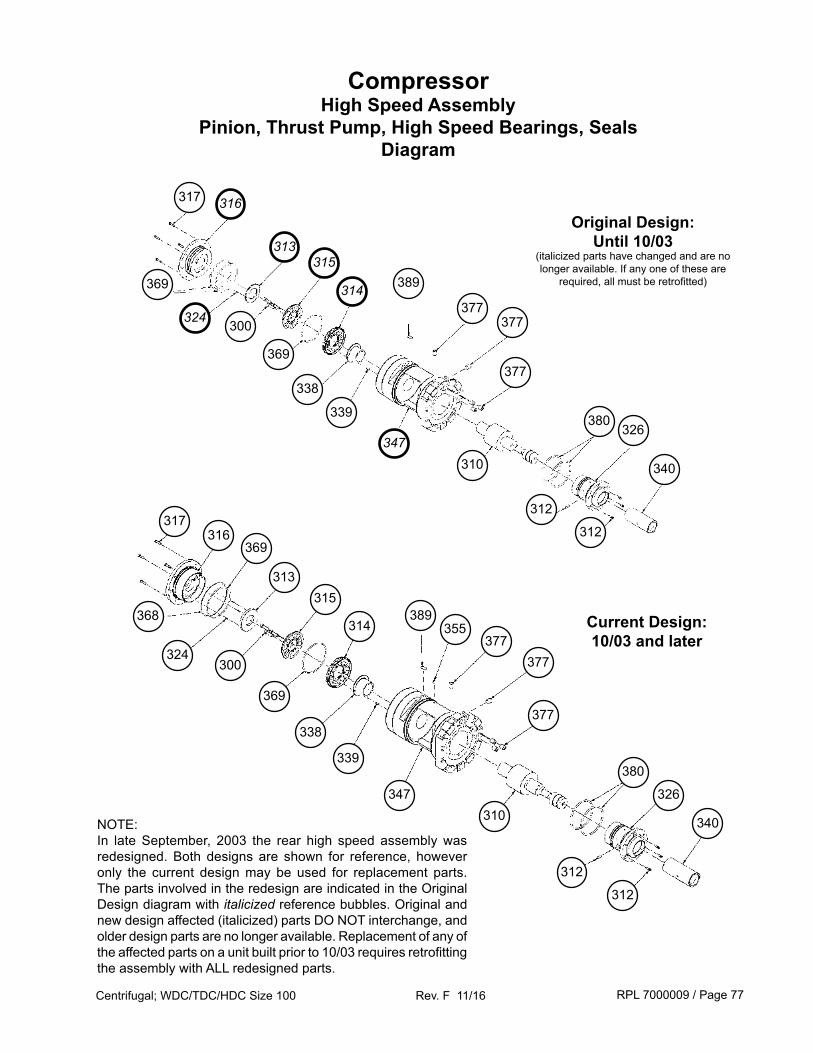
RPL 7000009 / Page 77Centrifugal; WDC/TDC/HDC Size 100 Rev. F 11/16
CompressorHigh Speed Assembly
Pinion, Thrust Pump, High Speed Bearings, SealsDiagram
317
369
315
314
324
316
313
300
339
377
389369
338
310
377
377
380
317
314
369
315
300
368
316
324
313
339
347
389
377
355
338
369
377
310
312
377
380
312
Current Design:10/03 and later
Original Design:Until 10/03
(italicized parts have changed and are no longer available. If any one of these are
required, all must be retrofitted)
NOTE:In late September, 2003 the rear high speed assembly was redesigned. Both designs are shown for reference, however only the current design may be used for replacement parts. The parts involved in the redesign are indicated in the Original Design diagram with italicized reference bubbles. Original and new design affected (italicized) parts DO NOT interchange, and older design parts are no longer available. Replacement of any of the affected parts on a unit built prior to 10/03 requires retrofitting the assembly with ALL redesigned parts.
326
312
312
340
326
340
347
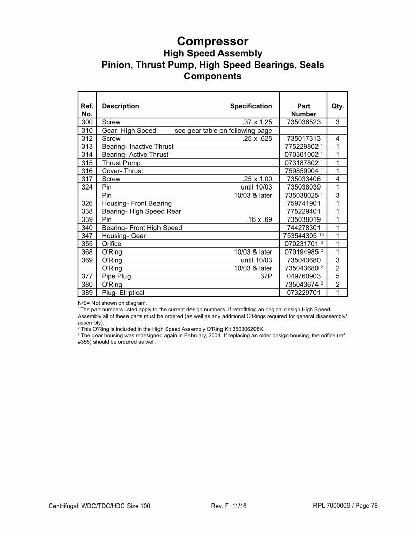
RPL 7000009 / Page 78Centrifugal; WDC/TDC/HDC Size 100 Rev. F 11/16
Ref. Description Specification Part Qty. No. Number 300 Screw .37 x 1.25 735036523 3 310 Gear- High Speed see gear table on following page 312 Screw .25 x .625 735017313 4 313 Bearing- Inactive Thrust 775229802 1 1 314 Bearing- Active Thrust 070301002 1 1 315 Thrust Pump 073187802 1 1 316 Cover- Thrust 759859904 1 1 317 Screw .25 x 1.00 735033406 4 324 Pin until 10/03 735038039 1 Pin 10/03 & later 735038025 1 3 326 Housing- Front Bearing 759741901 1 338 Bearing- High Speed Rear 775229401 1 339 Pin .16 x .69 735038019 1 340 Bearing- Front High Speed 744278301 1 347 Housing- Gear 753544305 1,3 1 355 Orifice 070231701 3 1 368 O'Ring 10/03 & later 070194985 2 1 369 O'Ring until 10/03 735043680 3 O'Ring 10/03 & later 735043680 2 2 377 Pipe Plug .37P 049760903 5 380 O'Ring 735043674 2 2 389 Plug- Elliptical 073229701 1N/S= Not shown on diagram.1 The part numbers listed apply to the current design numbers. If retrofitting an original design High Speed Assembly all of these parts must be ordered (as well as any additional O'Rings required for general disassembly/assembly).2 This O'Ring is included in the High Speed Assembly O'Ring Kit 350306208K.3 The gear housing was redesigned again in February, 2004. If replacing an older design housing, the orifice (ref. #355) should be ordered as well.
CompressorHigh Speed Assembly
Pinion, Thrust Pump, High Speed Bearings, SealsComponents
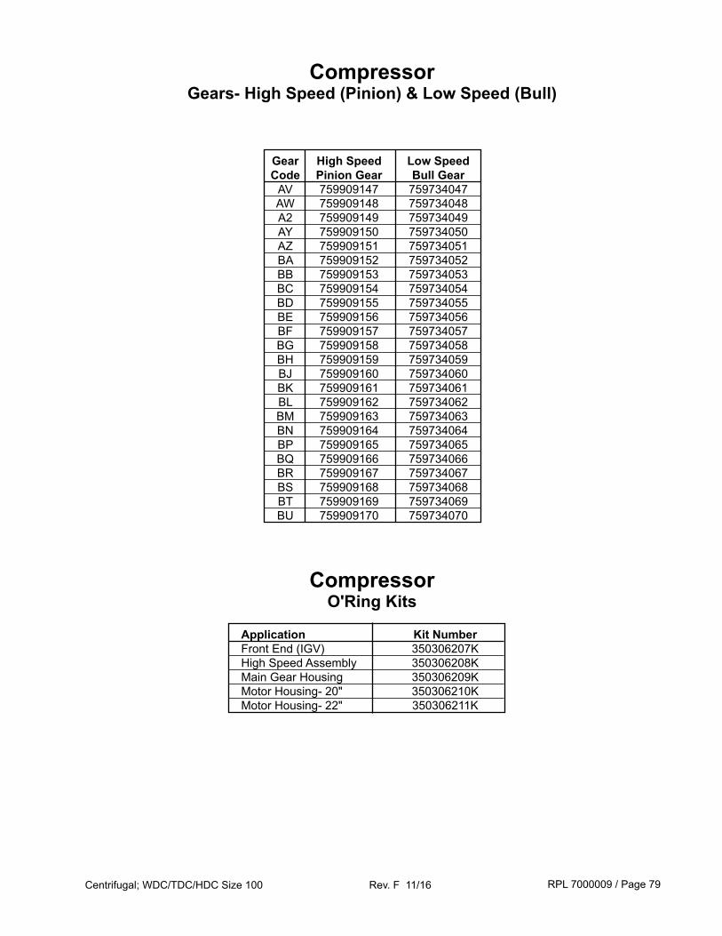
RPL 7000009 / Page 79Centrifugal; WDC/TDC/HDC Size 100 Rev. F 11/16
CompressorGears- High Speed (Pinion) & Low Speed (Bull)
Gear High Speed Low Speed Code Pinion Gear Bull Gear AV 759909147 759734047 AW 759909148 759734048 A2 759909149 759734049 AY 759909150 759734050 AZ 759909151 759734051 BA 759909152 759734052 BB 759909153 759734053 BC 759909154 759734054 BD 759909155 759734055 BE 759909156 759734056 BF 759909157 759734057 BG 759909158 759734058 BH 759909159 759734059 BJ 759909160 759734060 BK 759909161 759734061 BL 759909162 759734062 BM 759909163 759734063 BN 759909164 759734064 BP 759909165 759734065 BQ 759909166 759734066 BR 759909167 759734067 BS 759909168 759734068 BT 759909169 759734069 BU 759909170 759734070
CompressorO'Ring Kits
Application Kit Number Front End (IGV) 350306207K High Speed Assembly 350306208K Main Gear Housing 350306209K Motor Housing- 20" 350306210K Motor Housing- 22" 350306211K
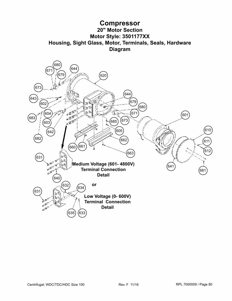
RPL 7000009 / Page 80Centrifugal; WDC/TDC/HDC Size 100 Rev. F 11/16
Compressor20" Motor Section
Motor Style: 3501177XXHousing, Sight Glass, Motor, Terminals, Seals, Hardware
Diagram
612
605
662
685 673
663
620
644679
671680
673
610
611
680
681641
671
679
644
Medium Voltage (601- 4800V)Terminal Connection
Detail
Low Voltage (0- 600V)Terminal Connection
Detail
661
601
or
660
642
603
604
682
683
602643
631
640
631634632
635 633

RPL 7000009 / Page 81Centrifugal; WDC/TDC/HDC Size 100 Rev. F 11/16
Compressor20" Motor Section
Motor Style: 3501177XXHousing, Sight Glass, Motor, Terminals, Seals, Hardware
Components
Ref. Description Specification Part Qty. No. Number 601 Stator 1 see motor tables on following pages 602 Cap- Flare 073243901 1 603 Screw .50 x 1.50 735033847 2 604 Flange- Block Off 070220401 1 605 Orifice Cap 070789312 1 610 Cover, End- Motor Housing 074542101 1 611 Washer- Lock .38 048164812 36 612 Screw .38 x 1.75 735033435 36 620 Housing- 20" Motor 071459702 1 631 Terminal- Motor Low Voltage Motor 0- 600V 074608102 6 Medium Voltage Motor 601- 4800V 074612002 3 632 Screw- Terminal .38 x 1.25 735033233 6 633 Nut- Terminal .38-16 040499906 6 634 Washer, Flat- Terminal .38 040500316 12 635 Washer, Lock- Terminal .38 048164812 6 640 Plug- Medium Volt Terminal 735017114 3 641 O'Ring- End Cover 070194954 2 1 642 O'Ring- Block Off 735073629 2 1 643 Orifice Assembly 074601902 1 644 O'Ring- Electrical Box 735073635 2 2 660 Angle- Mounting 350166101 1 661 Screw .75 x 1.50 735033873 2 662 Channel- Mounting 350166201 1 663 Screw .62 x 1.50 735033860 2 671 Washer- Lock 048164806 3 8 673 Screw #10 x .62 735036446 3 8 679 Terminal- 3 Pin 070260801 2 680 Electrical Box 330763801 2 681 Sightglass- Motor End Cover 015997816 2 682 Dowel 735068004 1 683 Plug w/O'Ring 735017101 1 685 Fitting- Orifice 070789308 1 N/S Insulation Kit- 20" Motor 331359301 1
N/S= Not shown on diagram.1 See Gear Housing Section for location of rotor/shaft assembly.2 This O'Ring is included in the 20" Motor Housing Assembly O'Ring Kit 350306210K.3 Units built prior to 2/03 used a ½" screw p/n 735036445 and no lock washers.

RPL 7000009 / Page 82Centrifugal; WDC/TDC/HDC Size 100 Rev. F 11/16
Compressor 20" Motor Section
Motors: Style 3501177XX- Stator, Rotor/Shaft Assy
1 Digits 9, 10, 11 in compressor model number. 2 Rotor and Low Speed Shaft shrunk fit together.
Ref. Motor Motor Motor Motor Stator Rotor No. Code 1 Voltage H.P. Part No. Part No. Shaft Assy 2
601 53Y 346/50 500 350117701 350117801 350188050 62U 380/60 600 350117701 350117801 350188050 53H 440/50 500 350117702 350117802 350188050 53F 380/50 500 350117703 350117803 350188050 53G 400/50 500 350117703 350117803 350188050 53K 415/50 500 350117703 350117803 350188050 62A 440/60 600 350117703 350117803 350188050 62R 460/60 600 350117703 350117803 350188050 62S 480/60 600 350117703 350117803 350188050 62D 575/60 600 350117704 350117804 350188050 623 2300/60 600 350117705 350117805 350188051 62M 2400/60 600 350117705 350117805 350188051 536 3000/50 500 350117706 350117806 350188051 62C 3300/60 600 350117707 350117807 350188051 53J 3300/50 500 350117708 350117808 350188051 62 4000/60 600 350117708 350117808 350188051 62L 4160/60 600 350117708 350117808 350188051 62Y 346/50 600 350117712 350117812 350188052 73U 380/60 725 350117712 350117812 350188052 62H 440/50 600 350117713 350117813 350188052 62F 380/50 600 350117714 350117814 350188052 62G 400/50 600 350117714 350117814 350188052 62K 415/50 600 350117714 350117814 350188052 73A 440/60 725 350117714 350117814 350188052 73R 460/60 725 350117714 350117814 350188052 73S 480/60 725 350117714 350117814 350188052 73D 575/60 725 350117715 350117815 350188052 733 2300/60 725 350117716 350117816 350188052 73M 2400/60 725 350117716 350117816 350188052 626 3000/50 600 350117717 350117817 350188052 73C 3300/60 725 350117718 350117818 350188052 62J 3300/50 600 350117719 350117819 350188052 73 4000/60 725 350117719 350117819 350188052 73L 4160/60 725 350117719 350117819 350188052 73Y 346/50 700 350117723 350117823 350188053 85U 380/60 850 350117723 350117823 350188053 73H 440/50 700 350117724 350117824 350188053 73F 380/50 700 350117725 350117825 350188053 73G 400/50 700 350117725 350117825 350188053 73K 415/50 700 350117725 350117825 350188053 85A 440/60 850 350117725 350117825 350188053 85R 460/60 850 350117725 350117825 350188053 85S 480/60 850 350117725 350117825 350188053 85D 575/60 850 350117726 350117826 350188053 853 2300/60 850 350117727 350117827 350188053 85M 2400/60 850 350117727 350117827 350188053 736 3000/50 700 350117728 350117828 350188053 85C 3300/60 850 350117729 350117829 350188053
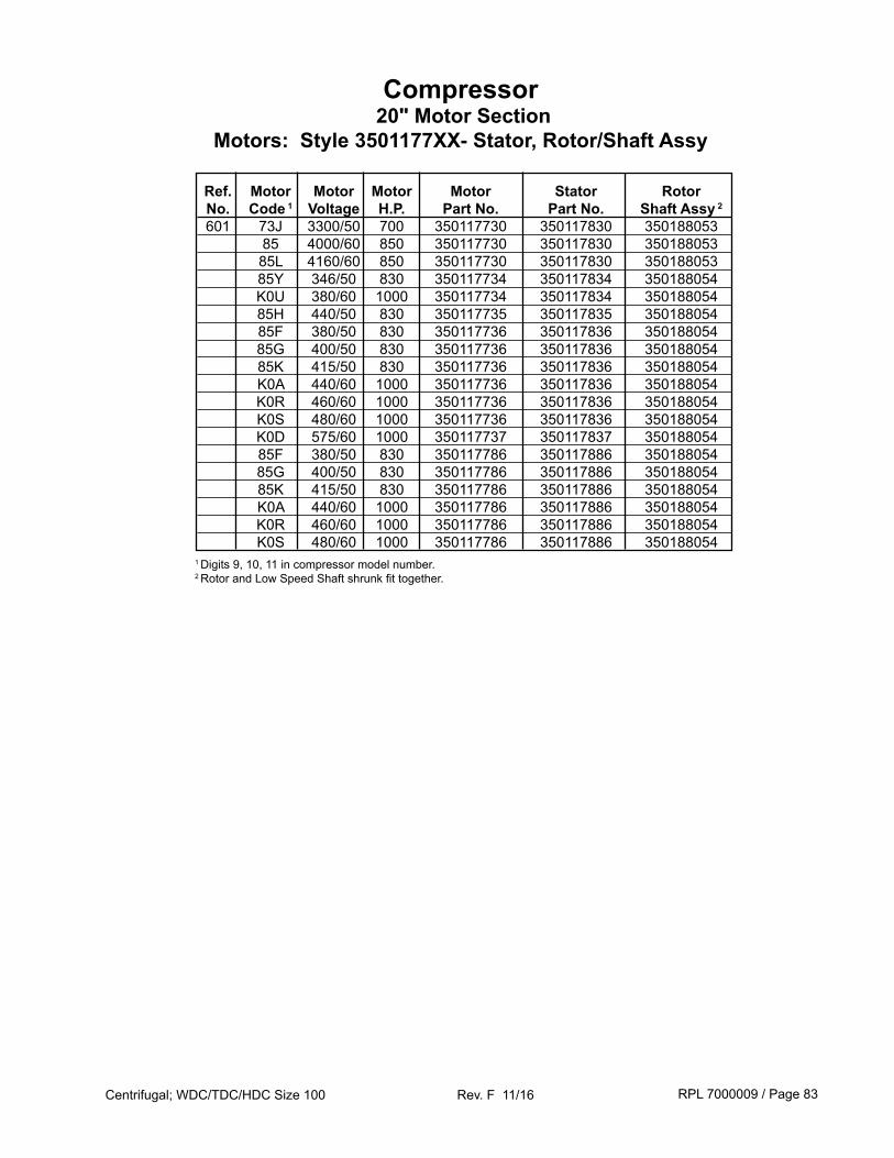
RPL 7000009 / Page 83Centrifugal; WDC/TDC/HDC Size 100 Rev. F 11/16
Compressor 20" Motor Section
Motors: Style 3501177XX- Stator, Rotor/Shaft Assy
1 Digits 9, 10, 11 in compressor model number. 2 Rotor and Low Speed Shaft shrunk fit together.
Ref. Motor Motor Motor Motor Stator Rotor No. Code 1 Voltage H.P. Part No. Part No. Shaft Assy 2
601 73J 3300/50 700 350117730 350117830 350188053 85 4000/60 850 350117730 350117830 350188053 85L 4160/60 850 350117730 350117830 350188053 85Y 346/50 830 350117734 350117834 350188054 K0U 380/60 1000 350117734 350117834 350188054 85H 440/50 830 350117735 350117835 350188054 85F 380/50 830 350117736 350117836 350188054 85G 400/50 830 350117736 350117836 350188054 85K 415/50 830 350117736 350117836 350188054 K0A 440/60 1000 350117736 350117836 350188054 K0R 460/60 1000 350117736 350117836 350188054 K0S 480/60 1000 350117736 350117836 350188054 K0D 575/60 1000 350117737 350117837 350188054 85F 380/50 830 350117786 350117886 350188054 85G 400/50 830 350117786 350117886 350188054 85K 415/50 830 350117786 350117886 350188054 K0A 440/60 1000 350117786 350117886 350188054 K0R 460/60 1000 350117786 350117886 350188054 K0S 480/60 1000 350117786 350117886 350188054
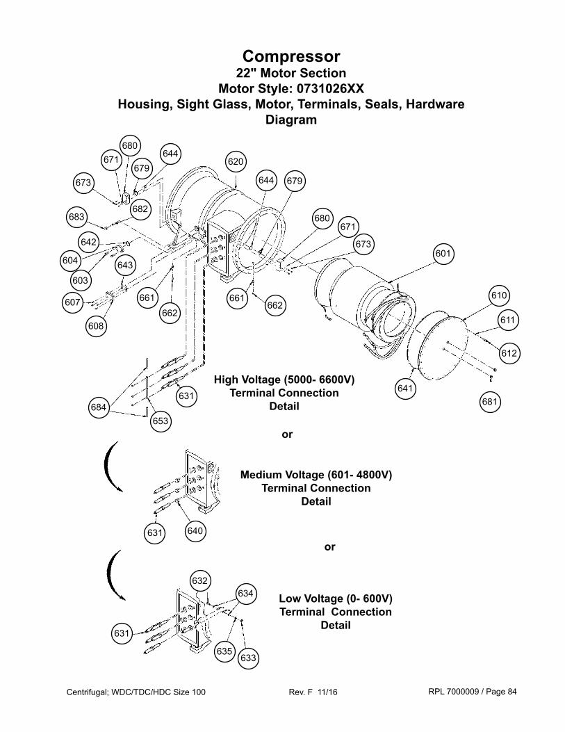
RPL 7000009 / Page 84Centrifugal; WDC/TDC/HDC Size 100 Rev. F 11/16
Compressor22" Motor Section
Motor Style: 0731026XXHousing, Sight Glass, Motor, Terminals, Seals, Hardware
Diagram
612
662
673
620644
679671
680
673
610
611
680
681641
671
679644
Medium Voltage (601- 4800V)Terminal Connection
Detail
Low Voltage (0- 600V)Terminal Connection
Detail
661
601
or
631
643
631
640631
634632
635633
653684
607
608
661
High Voltage (5000- 6600V)Terminal Connection
Detail
or
682683
642
662
604
603
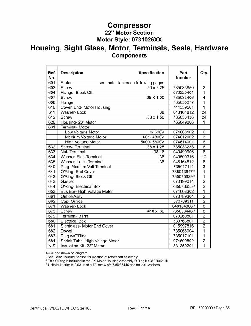
RPL 7000009 / Page 85Centrifugal; WDC/TDC/HDC Size 100 Rev. F 11/16
Compressor22" Motor Section
Motor Style: 0731026XXHousing, Sight Glass, Motor, Terminals, Seals, Hardware
Components
Ref. Description Specification Part Qty. No. Number 601 Stator 1 see motor tables on following pages 603 Screw .50 x 2.25 735033850 2 604 Flange- Block Off 070220401 1 607 Screw .25 X 1.00 735033406 4 608 Flange 735055277 1 610 Cover, End- Motor Housing 744359501 1 611 Washer- Lock .38 048164812 24 612 Screw .38 x 1.50 735033436 24 620 Housing- 20" Motor 765049006 1 631 Terminal- Motor Low Voltage Motor 0- 600V 074608102 6 Medium Voltage Motor 601- 4800V 074612002 3 High Voltage Motor 5000- 6600V 074614001 6 632 Screw- Terminal .38 x 1.25 735033233 6 633 Nut- Terminal .38-16 040499906 6 634 Washer, Flat- Terminal .38 040500316 12 635 Washer, Lock- Terminal .38 048164812 6 640 Plug- Medium Volt Terminal 735017114 3 641 O'Ring- End Cover 735043647 2 1 642 O'Ring- Block Off 735073629 2 1 643 Gasket 070199014 2 644 O'Ring- Electrical Box 735073635 2 2 653 Bus Bar- High Voltage Motor 074608302 1 661 Orifice Assy 070789304 2 662 Cap- Orifice 070789311 2 671 Washer- Lock 048164806 3 8 673 Screw #10 x .62 735036446 3 8 679 Terminal- 3 Pin 070260801 2 680 Electrical Box 330763801 2 681 Sightglass- Motor End Cover 015997816 2 682 Dowel 735068004 1 683 Plug w/O'Ring 735017101 1 684 Shrink Tube- High Volage Motor 074609802 2 N/S Insulation Kit- 22" Motor 331359201 1
N/S= Not shown on diagram. 1 See Gear Housing Section for location of rotor/shaft assembly.2 This O'Ring is included in the 22" Motor Housing Assembly O'Ring Kit 350306211K.3 Units built prior to 2/03 used a ½" screw p/n 735036445 and no lock washers.
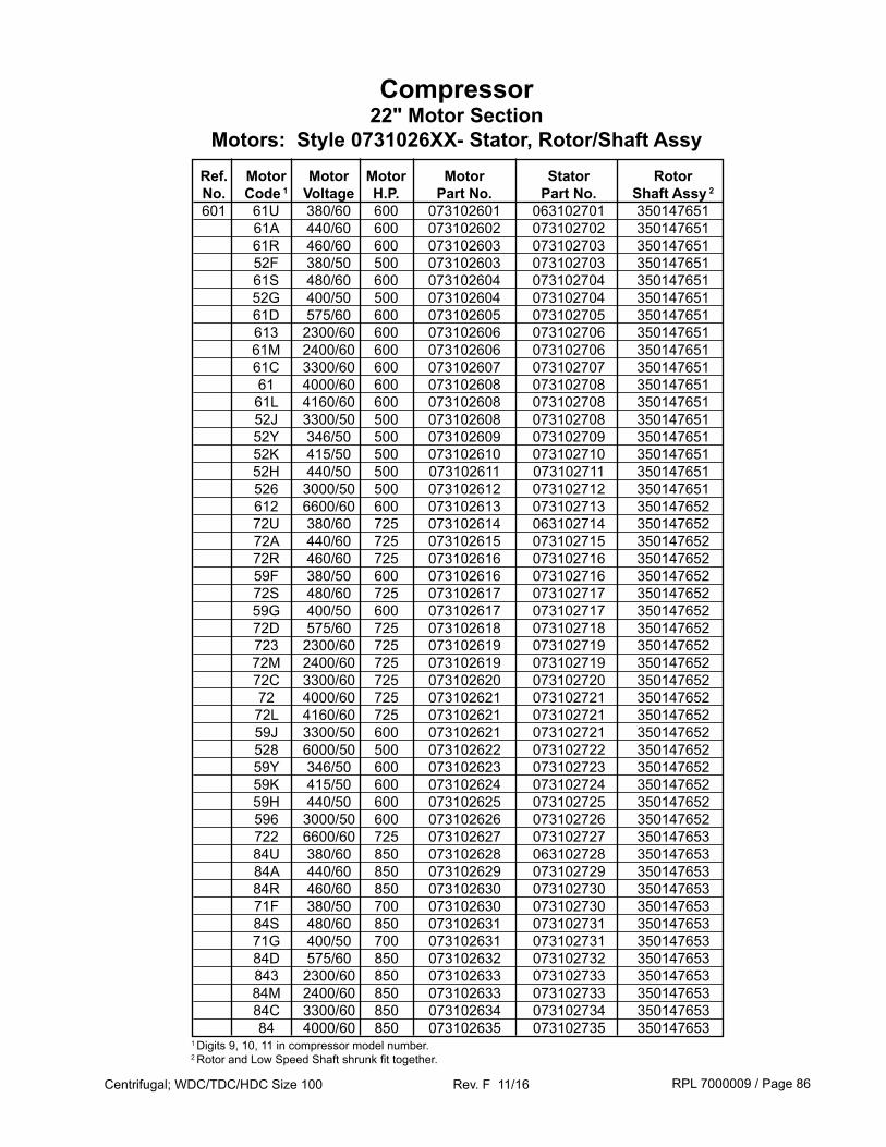
RPL 7000009 / Page 86Centrifugal; WDC/TDC/HDC Size 100 Rev. F 11/16
Compressor22" Motor Section
Motors: Style 0731026XX- Stator, Rotor/Shaft Assy
1 Digits 9, 10, 11 in compressor model number. 2 Rotor and Low Speed Shaft shrunk fit together.
Ref. Motor Motor Motor Motor Stator Rotor No. Code 1 Voltage H.P. Part No. Part No. Shaft Assy 2
601 61U 380/60 600 073102601 063102701 350147651 61A 440/60 600 073102602 073102702 350147651 61R 460/60 600 073102603 073102703 350147651 52F 380/50 500 073102603 073102703 350147651 61S 480/60 600 073102604 073102704 350147651 52G 400/50 500 073102604 073102704 350147651 61D 575/60 600 073102605 073102705 350147651 613 2300/60 600 073102606 073102706 350147651 61M 2400/60 600 073102606 073102706 350147651 61C 3300/60 600 073102607 073102707 350147651 61 4000/60 600 073102608 073102708 350147651 61L 4160/60 600 073102608 073102708 350147651 52J 3300/50 500 073102608 073102708 350147651 52Y 346/50 500 073102609 073102709 350147651 52K 415/50 500 073102610 073102710 350147651 52H 440/50 500 073102611 073102711 350147651 526 3000/50 500 073102612 073102712 350147651 612 6600/60 600 073102613 073102713 350147652 72U 380/60 725 073102614 063102714 350147652 72A 440/60 725 073102615 073102715 350147652 72R 460/60 725 073102616 073102716 350147652 59F 380/50 600 073102616 073102716 350147652 72S 480/60 725 073102617 073102717 350147652 59G 400/50 600 073102617 073102717 350147652 72D 575/60 725 073102618 073102718 350147652 723 2300/60 725 073102619 073102719 350147652 72M 2400/60 725 073102619 073102719 350147652 72C 3300/60 725 073102620 073102720 350147652 72 4000/60 725 073102621 073102721 350147652 72L 4160/60 725 073102621 073102721 350147652 59J 3300/50 600 073102621 073102721 350147652 528 6000/50 500 073102622 073102722 350147652 59Y 346/50 600 073102623 073102723 350147652 59K 415/50 600 073102624 073102724 350147652 59H 440/50 600 073102625 073102725 350147652 596 3000/50 600 073102626 073102726 350147652 722 6600/60 725 073102627 073102727 350147653 84U 380/60 850 073102628 063102728 350147653 84A 440/60 850 073102629 073102729 350147653 84R 460/60 850 073102630 073102730 350147653 71F 380/50 700 073102630 073102730 350147653 84S 480/60 850 073102631 073102731 350147653 71G 400/50 700 073102631 073102731 350147653 84D 575/60 850 073102632 073102732 350147653 843 2300/60 850 073102633 073102733 350147653 84M 2400/60 850 073102633 073102733 350147653 84C 3300/60 850 073102634 073102734 350147653 84 4000/60 850 073102635 073102735 350147653
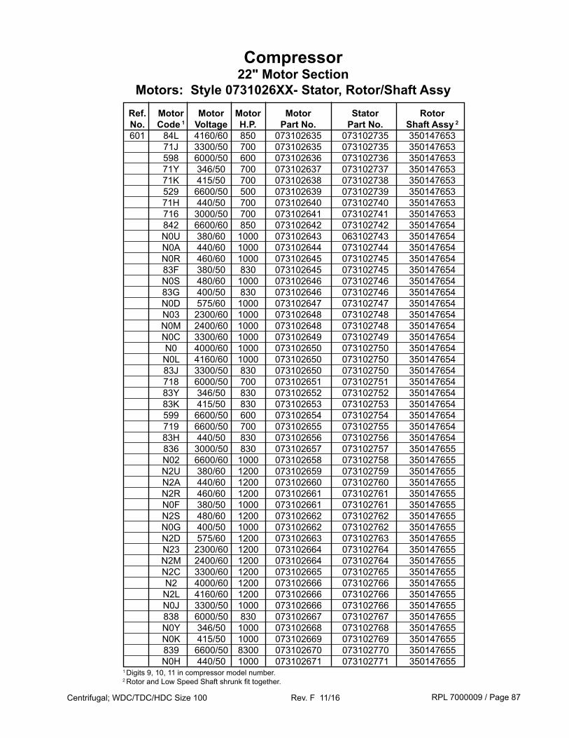
RPL 7000009 / Page 87Centrifugal; WDC/TDC/HDC Size 100 Rev. F 11/16
Compressor22" Motor Section
Motors: Style 0731026XX- Stator, Rotor/Shaft Assy
1 Digits 9, 10, 11 in compressor model number. 2 Rotor and Low Speed Shaft shrunk fit together.
Ref. Motor Motor Motor Motor Stator Rotor No. Code 1 Voltage H.P. Part No. Part No. Shaft Assy 2
601 84L 4160/60 850 073102635 073102735 350147653 71J 3300/50 700 073102635 073102735 350147653 598 6000/50 600 073102636 073102736 350147653 71Y 346/50 700 073102637 073102737 350147653 71K 415/50 700 073102638 073102738 350147653 529 6600/50 500 073102639 073102739 350147653 71H 440/50 700 073102640 073102740 350147653 716 3000/50 700 073102641 073102741 350147653 842 6600/60 850 073102642 073102742 350147654 N0U 380/60 1000 073102643 063102743 350147654 N0A 440/60 1000 073102644 073102744 350147654 N0R 460/60 1000 073102645 073102745 350147654 83F 380/50 830 073102645 073102745 350147654 N0S 480/60 1000 073102646 073102746 350147654 83G 400/50 830 073102646 073102746 350147654 N0D 575/60 1000 073102647 073102747 350147654 N03 2300/60 1000 073102648 073102748 350147654 N0M 2400/60 1000 073102648 073102748 350147654 N0C 3300/60 1000 073102649 073102749 350147654 N0 4000/60 1000 073102650 073102750 350147654 N0L 4160/60 1000 073102650 073102750 350147654 83J 3300/50 830 073102650 073102750 350147654 718 6000/50 700 073102651 073102751 350147654 83Y 346/50 830 073102652 073102752 350147654 83K 415/50 830 073102653 073102753 350147654 599 6600/50 600 073102654 073102754 350147654 719 6600/50 700 073102655 073102755 350147654 83H 440/50 830 073102656 073102756 350147654 836 3000/50 830 073102657 073102757 350147655 N02 6600/60 1000 073102658 073102758 350147655 N2U 380/60 1200 073102659 073102759 350147655 N2A 440/60 1200 073102660 073102760 350147655 N2R 460/60 1200 073102661 073102761 350147655 N0F 380/50 1000 073102661 073102761 350147655 N2S 480/60 1200 073102662 073102762 350147655 N0G 400/50 1000 073102662 073102762 350147655 N2D 575/60 1200 073102663 073102763 350147655 N23 2300/60 1200 073102664 073102764 350147655 N2M 2400/60 1200 073102664 073102764 350147655 N2C 3300/60 1200 073102665 073102765 350147655 N2 4000/60 1200 073102666 073102766 350147655 N2L 4160/60 1200 073102666 073102766 350147655 N0J 3300/50 1000 073102666 073102766 350147655 838 6000/50 830 073102667 073102767 350147655 N0Y 346/50 1000 073102668 073102768 350147655 N0K 415/50 1000 073102669 073102769 350147655 839 6600/50 8300 073102670 073102770 350147655 N0H 440/50 1000 073102671 073102771 350147655
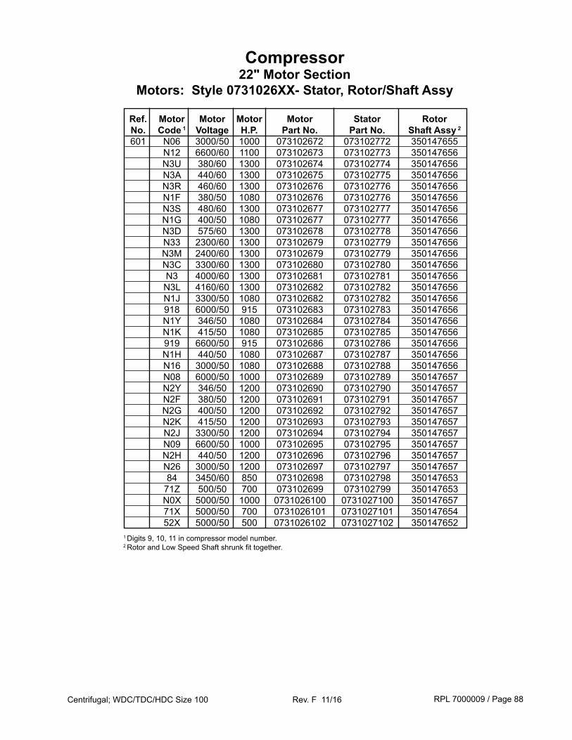
RPL 7000009 / Page 88Centrifugal; WDC/TDC/HDC Size 100 Rev. F 11/16
Compressor22" Motor Section
Motors: Style 0731026XX- Stator, Rotor/Shaft Assy
1 Digits 9, 10, 11 in compressor model number. 2 Rotor and Low Speed Shaft shrunk fit together.
Ref. Motor Motor Motor Motor Stator Rotor No. Code 1 Voltage H.P. Part No. Part No. Shaft Assy 2
601 N06 3000/50 1000 073102672 073102772 350147655 N12 6600/60 1100 073102673 073102773 350147656 N3U 380/60 1300 073102674 073102774 350147656 N3A 440/60 1300 073102675 073102775 350147656 N3R 460/60 1300 073102676 073102776 350147656 N1F 380/50 1080 073102676 073102776 350147656 N3S 480/60 1300 073102677 073102777 350147656 N1G 400/50 1080 073102677 073102777 350147656 N3D 575/60 1300 073102678 073102778 350147656 N33 2300/60 1300 073102679 073102779 350147656 N3M 2400/60 1300 073102679 073102779 350147656 N3C 3300/60 1300 073102680 073102780 350147656 N3 4000/60 1300 073102681 073102781 350147656 N3L 4160/60 1300 073102682 073102782 350147656 N1J 3300/50 1080 073102682 073102782 350147656 918 6000/50 915 073102683 073102783 350147656 N1Y 346/50 1080 073102684 073102784 350147656 N1K 415/50 1080 073102685 073102785 350147656 919 6600/50 915 073102686 073102786 350147656 N1H 440/50 1080 073102687 073102787 350147656 N16 3000/50 1080 073102688 073102788 350147656 N08 6000/50 1000 073102689 073102789 350147657 N2Y 346/50 1200 073102690 073102790 350147657 N2F 380/50 1200 073102691 073102791 350147657 N2G 400/50 1200 073102692 073102792 350147657 N2K 415/50 1200 073102693 073102793 350147657 N2J 3300/50 1200 073102694 073102794 350147657 N09 6600/50 1000 073102695 073102795 350147657 N2H 440/50 1200 073102696 073102796 350147657 N26 3000/50 1200 073102697 073102797 350147657 84 3450/60 850 073102698 073102798 350147653 71Z 500/50 700 073102699 073102799 350147653 N0X 5000/50 1000 0731026100 0731027100 350147657 71X 5000/50 700 0731026101 0731027101 350147654 52X 5000/50 500 0731026102 0731027102 350147652
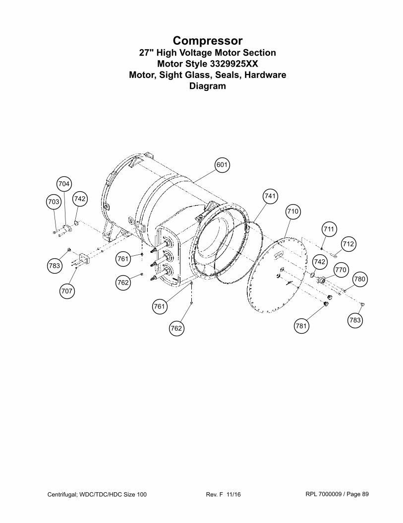
RPL 7000009 / Page 89Centrifugal; WDC/TDC/HDC Size 100 Rev. F 11/16
Compressor27" High Voltage Motor Section
Motor Style 3329925XXMotor, Sight Glass, Seals, Hardware
Diagram
741
710
712
711
781
742770
780
783
761
762
742
704
703
707
783
761
762
601
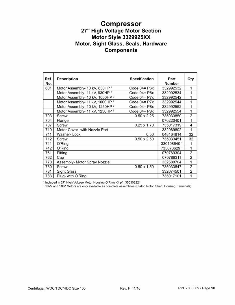
RPL 7000009 / Page 90Centrifugal; WDC/TDC/HDC Size 100 Rev. F 11/16
Compressor27" High Voltage Motor Section
Motor Style 3329925XXMotor, Sight Glass, Seals, Hardware
Components
Ref. Description Specification Part Qty. No. Number 601 Motor Assembly- 10 kV, 830HP 2 Code 04= P6x 332992532 1 Motor Assembly- 11 kV, 830HP 2 Code 04= P6x 332992534 1 Motor Assembly- 10 kV, 1000HP 2 Code 04= P7x 332992542 1 Motor Assembly- 11 kV, 1000HP 2 Code 04= P7x 332992544 1 Motor Assembly- 10 kV, 1250HP 2 Code 04= P8x 332992552 1 Motor Assembly- 11 kV, 1250HP 2 Code 04= P8x 332992554 1 703 Screw 0.50 x 2.25 735033850 2 704 Flange 070220401 1 707 Screw 0.25 x 1.70 735017319 4 710 Motor Cover- with Nozzle Port 332989802 1 711 Washer- Lock 0.50 048164814 32 712 Screw 0.50 x 2.50 735033451 32 741 O'Ring 330198640 1 1 742 O'Ring 735073629 1 1 761 Fitting 070789304 2 762 Cap 070789311 2 770 Assembly- Motor Spray Nozzle 332588704 1 780 Screw 0.50 x 1.50 735033847 2 781 Sight Glass 332674501 2 783 Plug- with O'Ring 735017101 11 Included in 27" High Voltage Motor Housing O'Ring Kit p/n 350306221.2 10kV and 11kV Motors are only available as complete assemblies (Stator, Rotor, Shaft, Housing, Terminals).
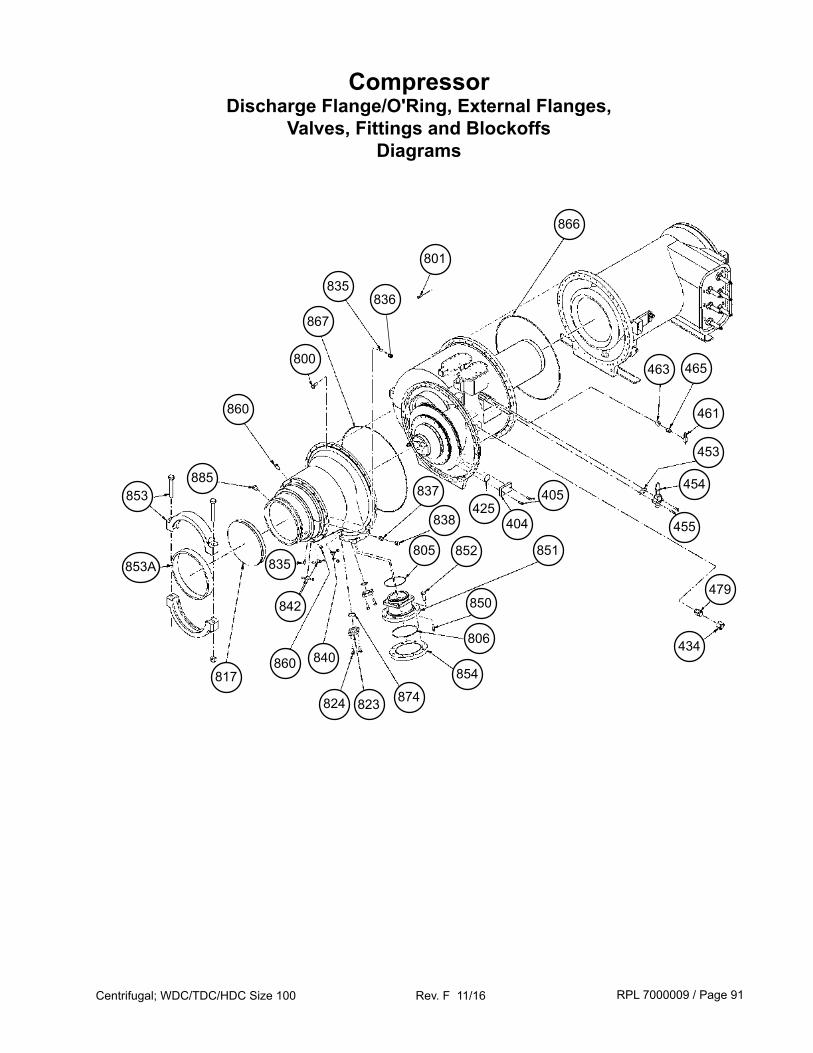
RPL 7000009 / Page 91Centrifugal; WDC/TDC/HDC Size 100 Rev. F 11/16
CompressorDischarge Flange/O'Ring, External Flanges,
Valves, Fittings and BlockoffsDiagrams
853A
853
860
860
800
817
823824
850
852
874
854
851
835
837
806
867
835
885
805
838
801
866
479
425404
405
434
463 465
461
453
454
455
842
840
836
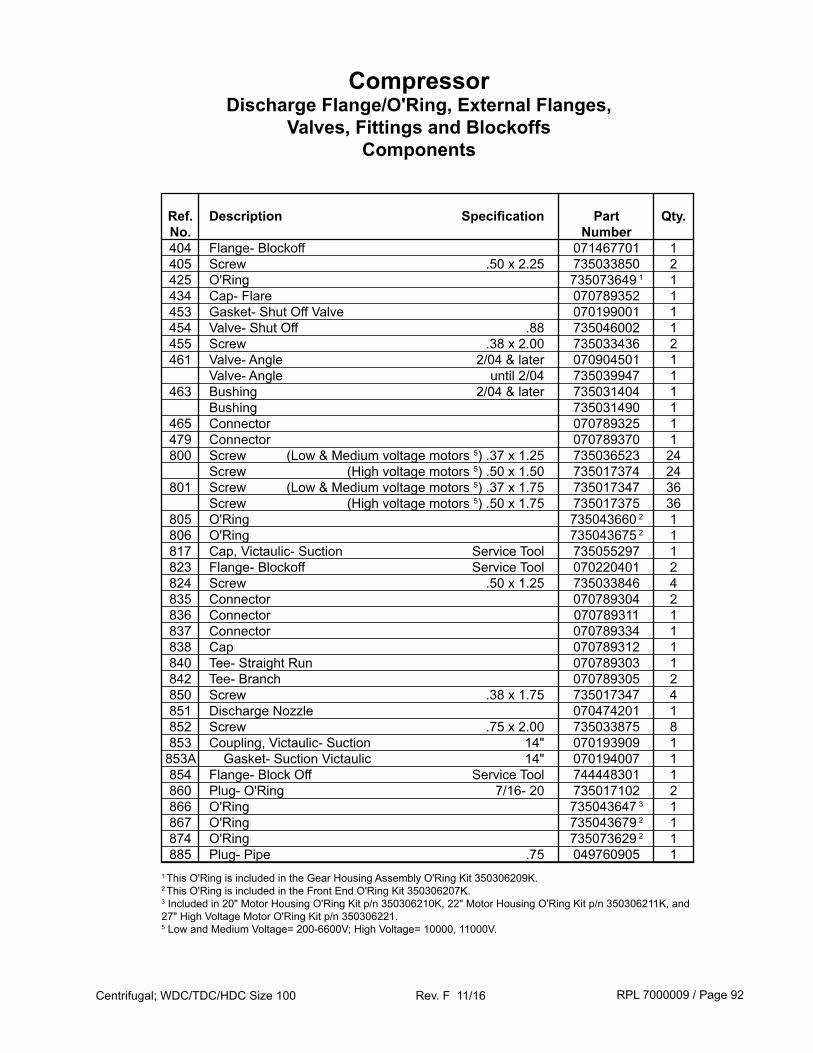
RPL 7000009 / Page 92Centrifugal; WDC/TDC/HDC Size 100 Rev. F 11/16
CompressorDischarge Flange/O'Ring, External Flanges,
Valves, Fittings and BlockoffsComponents
Ref. Description Specification Part Qty. No. Number 404 Flange- Blockoff 071467701 1 405 Screw .50 x 2.25 735033850 2 425 O'Ring 735073649 1 1 434 Cap- Flare 070789352 1 453 Gasket- Shut Off Valve 070199001 1 454 Valve- Shut Off .88 735046002 1 455 Screw .38 x 2.00 735033436 2 461 Valve- Angle 2/04 & later 070904501 1 Valve- Angle until 2/04 735039947 1 463 Bushing 2/04 & later 735031404 1 Bushing 735031490 1 465 Connector 070789325 1 479 Connector 070789370 1 800 Screw (Low & Medium voltage motors 5) .37 x 1.25 735036523 24 Screw (High voltage motors 5) .50 x 1.50 735017374 24 801 Screw (Low & Medium voltage motors 5) .37 x 1.75 735017347 36 Screw (High voltage motors 5) .50 x 1.75 735017375 36 805 O'Ring 735043660 2 1 806 O'Ring 735043675 2 1 817 Cap, Victaulic- Suction Service Tool 735055297 1 823 Flange- Blockoff Service Tool 070220401 2 824 Screw .50 x 1.25 735033846 4 835 Connector 070789304 2 836 Connector 070789311 1 837 Connector 070789334 1 838 Cap 070789312 1 840 Tee- Straight Run 070789303 1 842 Tee- Branch 070789305 2 850 Screw .38 x 1.75 735017347 4 851 Discharge Nozzle 070474201 1 852 Screw .75 x 2.00 735033875 8 853 Coupling, Victaulic- Suction 14" 070193909 1 853A Gasket- Suction Victaulic 14" 070194007 1 854 Flange- Block Off Service Tool 744448301 1 860 Plug- O'Ring 7/16- 20 735017102 2 866 O'Ring 735043647 3 1 867 O'Ring 735043679 2 1 874 O'Ring 735073629 2 1 885 Plug- Pipe .75 049760905 11 This O'Ring is included in the Gear Housing Assembly O'Ring Kit 350306209K.2 This O'Ring is included in the Front End O'Ring Kit 350306207K.3 Included in 20" Motor Housing O'Ring Kit p/n 350306210K, 22" Motor Housing O'Ring Kit p/n 350306211K, and 27" High Voltage Motor O'Ring Kit p/n 350306221.5 Low and Medium Voltage= 200-6600V; High Voltage= 10000, 11000V.
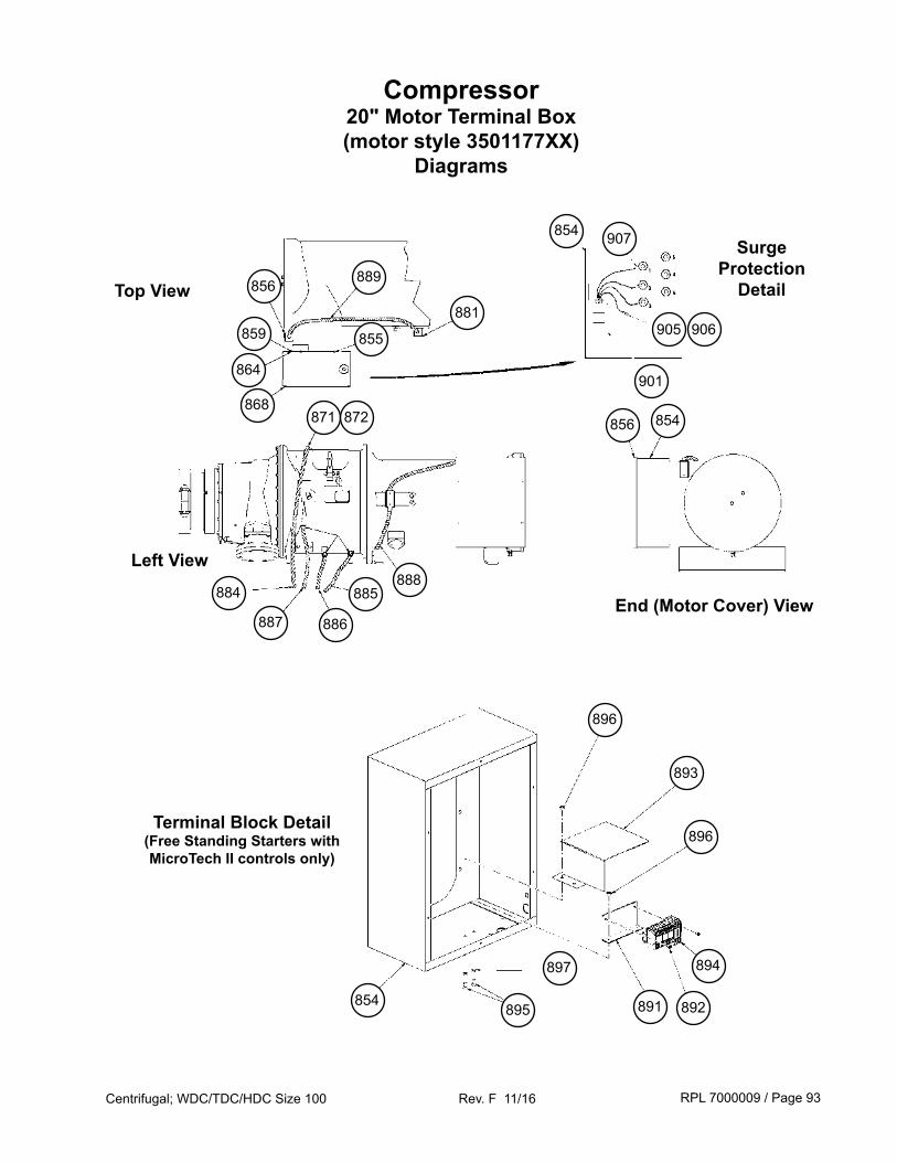
RPL 7000009 / Page 93Centrifugal; WDC/TDC/HDC Size 100 Rev. F 11/16
Compressor20" Motor Terminal Box(motor style 3501177XX)
Diagrams
Surge Protection
Detail
901
Top View
Left View
End (Motor Cover) View
905 906
907
889856
859
868
864
881
854
885
871
888
886887
884
856
855
854
872
895 891
897
892
894
896
893
896
854
Terminal Block Detail(Free Standing Starters with MicroTech II controls only)
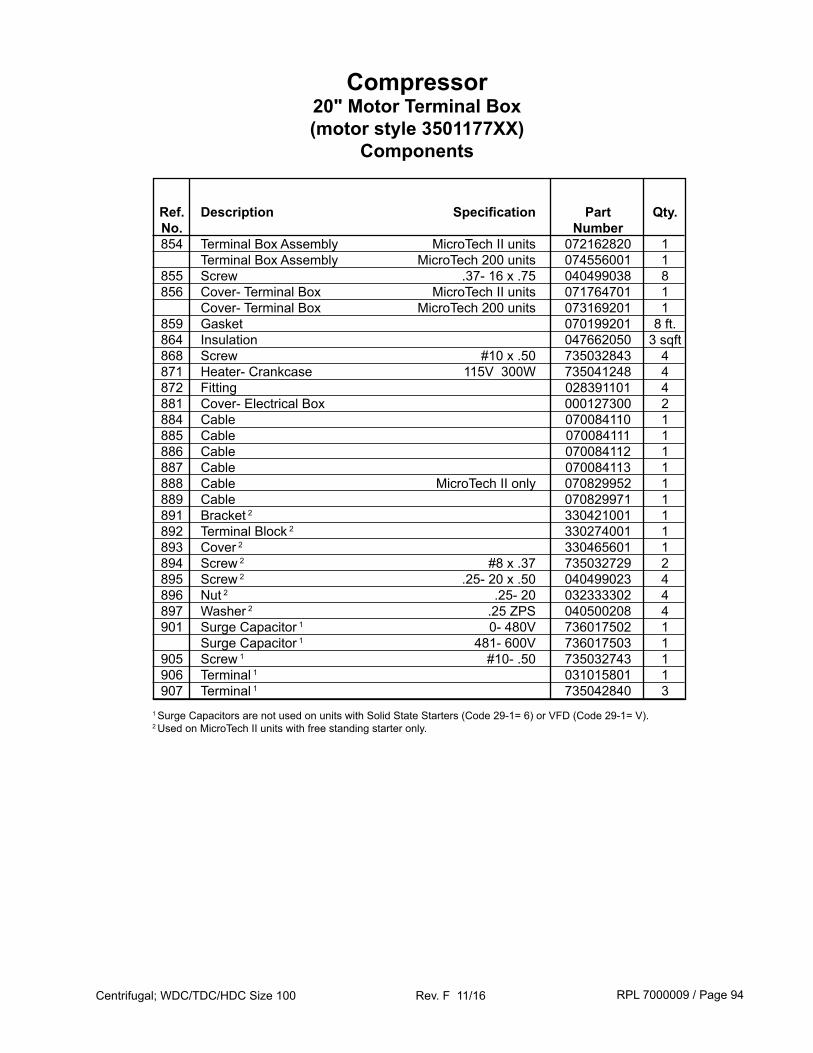
RPL 7000009 / Page 94Centrifugal; WDC/TDC/HDC Size 100 Rev. F 11/16
Ref. Description Specification Part Qty. No. Number 854 Terminal Box Assembly MicroTech II units 072162820 1 Terminal Box Assembly MicroTech 200 units 074556001 1 855 Screw .37- 16 x .75 040499038 8 856 Cover- Terminal Box MicroTech II units 071764701 1 Cover- Terminal Box MicroTech 200 units 073169201 1 859 Gasket 070199201 8 ft. 864 Insulation 047662050 3 sqft 868 Screw #10 x .50 735032843 4 871 Heater- Crankcase 115V 300W 735041248 4 872 Fitting 028391101 4 881 Cover- Electrical Box 000127300 2 884 Cable 070084110 1 885 Cable 070084111 1 886 Cable 070084112 1 887 Cable 070084113 1 888 Cable MicroTech II only 070829952 1 889 Cable 070829971 1 891 Bracket 2 330421001 1 892 Terminal Block 2 330274001 1 893 Cover 2 330465601 1 894 Screw 2 #8 x .37 735032729 2 895 Screw 2 .25- 20 x .50 040499023 4 896 Nut 2 .25- 20 032333302 4 897 Washer 2 .25 ZPS 040500208 4 901 Surge Capacitor 1 0- 480V 736017502 1 Surge Capacitor 1 481- 600V 736017503 1 905 Screw 1 #10- .50 735032743 1 906 Terminal 1 031015801 1 907 Terminal 1 735042840 31 Surge Capacitors are not used on units with Solid State Starters (Code 29-1= 6) or VFD (Code 29-1= V).2 Used on MicroTech II units with free standing starter only.
Compressor20" Motor Terminal Box(motor style 3501177XX)
Components
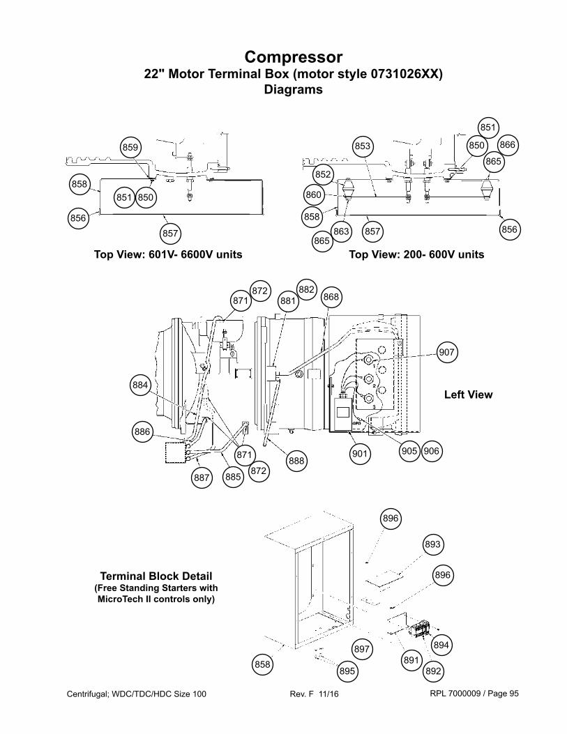
RPL 7000009 / Page 95Centrifugal; WDC/TDC/HDC Size 100 Rev. F 11/16
Compressor22" Motor Terminal Box (motor style 0731026XX)
Diagrams
895891
897
892
894
896
893
896
858
901
Top View: 601V- 6600V units
Left View
905 906
907
858850
857
851
871872
863856 858
860
859
852
Terminal Block Detail(Free Standing Starters with MicroTech II controls only)
857
853
856
850
865
866
851
Top View: 200- 600V units865
881882
868
884
886
887 885
871 888872
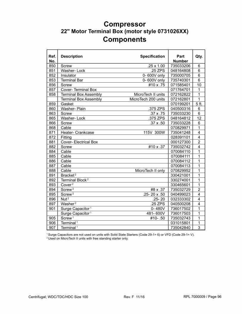
RPL 7000009 / Page 96Centrifugal; WDC/TDC/HDC Size 100 Rev. F 11/16
Compressor22" Motor Terminal Box (motor style 0731026XX)
Components
Ref. Description Specification Part Qty. No. Number 850 Screw .25 x 1.00 735033206 6 851 Washer- Lock .25 ZPS 048164808 6 852 Insulator 0- 600V only 735000705 6 853 Terminal Bar 0- 600V only 735740301 6 856 Screw #10 x .75 071585401 10 857 Cover- Terminal Box 071764701 1 858 Terminal Box Assembly MicroTech II units 072162822 1 Terminal Box Assembly MicroTech 200 units 072162801 1 859 Gasket 070199201 5 ft. 860 Washer- Plain .375 ZPS 040500316 6 863 Screw .37 x .75 735033230 6 865 Washer- Lock .375 ZPS 048164812 12 866 Screw .37 x .50 735033228 6 868 Cable 070829971 1 871 Heater- Crankcase 115V 300W 735041248 4 872 Fitting 028391101 4 881 Cover- Electrical Box 000127300 2 882 Screw #10 x .37 735032742 4 884 Cable 070084110 1 885 Cable 070084111 1 886 Cable 070084112 1 887 Cable 070084113 1 888 Cable MicroTech II only 070829952 1 891 Bracket 2 330421001 1 892 Terminal Block 2 330274001 1 893 Cover 2 330465601 1 894 Screw 2 #8 x .37 735032729 2 895 Screw 2 .25- 20 x .50 040499023 4 896 Nut 2 .25- 20 032333302 4 897 Washer 2 .25 ZPS 040500208 4 901 Surge Capacitor 1 0- 480V 736017502 1 Surge Capacitor 1 481- 600V 736017503 1 905 Screw 1 #10- .50 735032743 1 906 Terminal 1 031015801 1 907 Terminal 1 735042840 31 Surge Capacitors are not used on units with Solid State Starters (Code 29-1= 6) or VFD (Code 29-1= V).2 Used on MicroTech II units with free standing starter only.

RPL 7000009 / Page 97Centrifugal; WDC/TDC/HDC Size 100 Rev. F 11/16
Compressor27" High Voltage Motor Terminal Box (motor style 3329925XX)
Diagram and Components
871 872
858
871 872
Ref. Description Specification Part Qty. No. Number 858 Terminal Box 333610201 1 871 Crankcase Heater 735041248 4 872 Fitting for Crankcase Heater 028391101 4
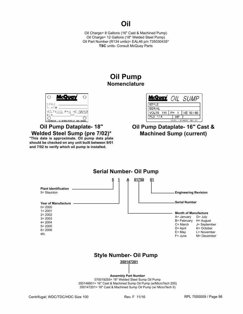
RPL 7000009 / Page 98Centrifugal; WDC/TDC/HDC Size 100 Rev. F 11/16
350147201
Assembly Part Number070019255= 18" Welded Steel Sump Oil Pump
350146601= 16" Cast & Machined Sump Oil Pump (w/MicroTech 200)350147201= 16" Cast & Machined Sump Oil Pump (w/ MicroTech II)
Style Number- Oil Pump
5 1 A 01750 01
Plant Identification 5= Staunton
Serial NumberYear of Manufacture0= 20001= 20012= 20023= 20034= 20045= 20056= 2006etc.
Month of ManufactureA= JanuaryB= FebruaryC= MarchD= AprilE= MayF= June
G= JulyH= AugustJ= SeptemberK= OctoberL= NovemberM= December
Serial Number- Oil Pump
Engineering Revision
Oil PumpNomenclature
Oil Pump Dataplate- 18" Welded Steel Sump (pre 7/02)*
*This date is approximate. Oil pump data plate should be checked on any unit built between 9/01 and 7/02 to verify which oil pump is installed.
Oil Pump Dataplate- 16" Cast & Machined Sump (current)
OilOil Charge= 8 Gallons (16" Cast & Machined Pump)
Oil Charge= 12 Gallons (18" Welded Steel Pump)Oil Part Number (R134 units)= EAL46 p/n 735030435*
TSC units- Consult McQuay Parts
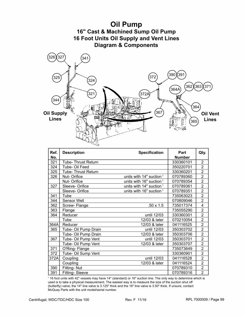
RPL 7000009 / Page 99Centrifugal; WDC/TDC/HDC Size 100 Rev. F 11/16
Oil Pump16" Cast & Machined Sump Oil Pump
16 Foot Units Oil Supply and Vent LinesDiagram & Components
Ref. Description Specification Part Qty. No. Number 321 Tube- Thrust Return 330360101 2 324 Tube- Oil Feed 350220701 2 325 Tube- Thrust Return 330360201 2 326 Nut- Orifice units with 14" suction 1 070789360 2 Nut- Orifice units with 16" suction 1 070789354 2 327 Sleeve- Orifice units with 14" suction 1 070789361 2 Sleeve- Orifice units with 16" suction 1 070789351 2 341 Tube 735063023 2 344 Sensor Well 070809046 2 362 Screw- Flange .50 x 1.5 735017374 4 363 Flange 735055290 2 364 Reducer until 12/03 330360301 2 Tube 12/03 & later 070210054 2 364A Reducer 12/03 & later 041116525 2 365 Tube- Oil Pump Drain until 12/03 350303702 2 Tube- Oil Pump Drain 12/03 & later 350303706 2 367 Tube- Oil Pump Vent until 12/03 350303701 2 Tube- Oil Pump Vent 12/03 & later 350303707 2 371 O'Ring- Flange 735073649 2 372 Tube- Oil Sump Vent 330360901 2 372A Coupling until 12/03 041116528 2 Coupling 12/03 & later 041116524 2 390 Fitting- Nut 070789310 2 391 Fitting- Sleeve 070789316 2
Oil Supply Lines
Oil VentLines
327326
325
344
341
324
321
391390
372A
367
372
364A
364
371363362
365
1 16 foot units with 42" vessels may have 14" (standard) or 16" suction line. The only way to determine which is used is to take a physical measurement. The easiest way is to measure the size of the suction shut off (butterfly) valve; the 14" line valve is 3.125" thick and the 16" line valve is 3.50" thick. If unsure, contact McQuay Parts with the unit model/serial number.
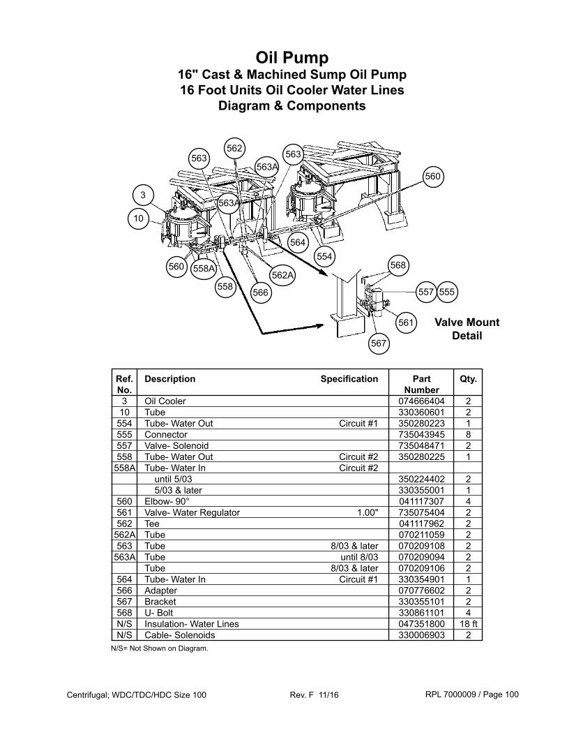
RPL 7000009 / Page 100Centrifugal; WDC/TDC/HDC Size 100 Rev. F 11/16
Oil Pump16" Cast & Machined Sump Oil Pump 16 Foot Units Oil Cooler Water Lines
Diagram & Components
Ref. Description Specification Part Qty. No. Number 3 Oil Cooler 074666404 2 10 Tube 330360601 2 554 Tube- Water Out Circuit #1 350280223 1 555 Connector 735043945 8 557 Valve- Solenoid 735048471 2 558 Tube- Water Out Circuit #2 350280225 1 558A Tube- Water In Circuit #2 until 5/03 350224402 2 5/03 & later 330355001 1 560 Elbow- 90° 041117307 4 561 Valve- Water Regulator 1.00" 735075404 2 562 Tee 041117962 2 562A Tube 070211059 2 563 Tube 8/03 & later 070209108 2 563A Tube until 8/03 070209094 2 Tube 8/03 & later 070209106 2 564 Tube- Water In Circuit #1 330354901 1 566 Adapter 070776602 2 567 Bracket 330355101 2 568 U- Bolt 330861101 4 N/S Insulation- Water Lines 047351800 18 ft N/S Cable- Solenoids 330006903 2
Valve Mount Detail
560
560
562 563563A
563
563A
562A558A
558
3
10
566
567
561
568
557 555
564554
N/S= Not Shown on Diagram.
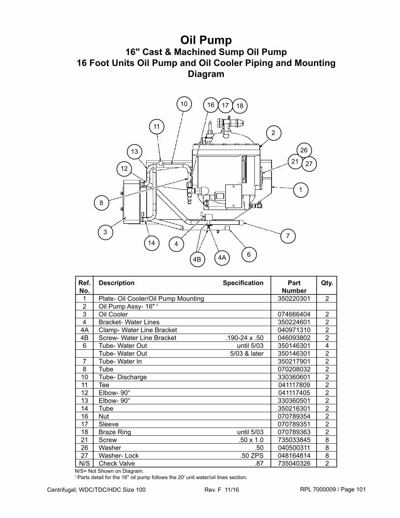
RPL 7000009 / Page 101Centrifugal; WDC/TDC/HDC Size 100 Rev. F 11/16
Oil Pump16" Cast & Machined Sump Oil Pump
16 Foot Units Oil Pump and Oil Cooler Piping and MountingDiagram
Ref. Description Specification Part Qty. No. Number 1 Plate- Oil Cooler/Oil Pump Mounting 350220301 2 2 Oil Pump Assy- 16" 1 3 Oil Cooler 074666404 2 4 Bracket- Water Lines 350224601 2 4A Clamp- Water Line Bracket 040971310 2 4B Screw- Water Line Bracket .190-24 x .50 046093802 2 6 Tube- Water Out until 5/03 350146301 4 Tube- Water Out 5/03 & later 350146301 2 7 Tube- Water In 350217901 2 8 Tube 070208032 2 10 Tube- Discharge 330360601 2 11 Tee 041117809 2 12 Elbow- 90° 041117405 2 13 Elbow- 90° 330360501 2 14 Tube 350216301 2 16 Nut 070789354 2 17 Sleeve 070789351 2 18 Braze Ring until 5/03 070789363 2 21 Screw .50 x 1.0 735033845 8 26 Washer .50 040500311 8 27 Washer- Lock .50 ZPS 048164814 8 N/S Check Valve .87 735040326 2
211
16
13
12
3
10
4B6
7
1
21
4A
14 4
N/S= Not Shown on Diagram.1 Parts detail for the 16" oil pump follows the 20' unit water/oil lines section.
26
27
17 18
8
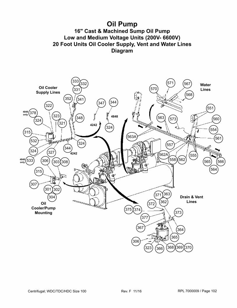
RPL 7000009 / Page 102Centrifugal; WDC/TDC/HDC Size 100 Rev. F 11/16
Oil Pump16" Cast & Machined Sump Oil Pump
Low and Medium Voltage Units (200V- 6600V)20 Foot Units Oil Cooler Supply, Vent and Water Lines
Diagram
Drain & Vent Lines
363
362
373
372
365
374375
364
368
371
369
Oil Cooler Supply Lines
Oil Cooler/Pump
Mounting
WaterLines
366323306
377
367
307302
304
301
315
306 303 308
344
332331
341347
348
333
321
352
323
322
324
532
327
344
324
563A
551
568
566555
562
557
573563
561
560
554
571 567570
315
324
3244242
4848
4242 562A558 565
564
3784848 only
5334848 only
370
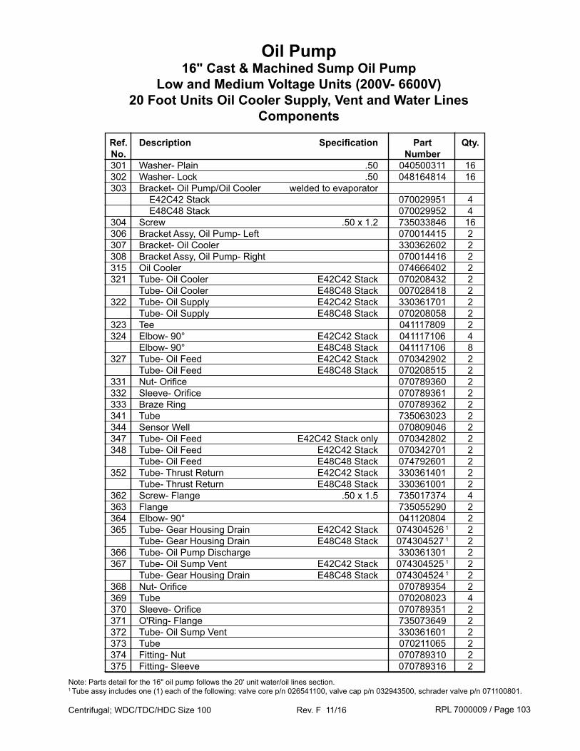
RPL 7000009 / Page 103Centrifugal; WDC/TDC/HDC Size 100 Rev. F 11/16
Ref. Description Specification Part Qty. No. Number 301 Washer- Plain .50 040500311 16 302 Washer- Lock .50 048164814 16 303 Bracket- Oil Pump/Oil Cooler welded to evaporator E42C42 Stack 070029951 4 E48C48 Stack 070029952 4 304 Screw .50 x 1.2 735033846 16 306 Bracket Assy, Oil Pump- Left 070014415 2 307 Bracket- Oil Cooler 330362602 2 308 Bracket Assy, Oil Pump- Right 070014416 2 315 Oil Cooler 074666402 2 321 Tube- Oil Cooler E42C42 Stack 070208432 2 Tube- Oil Cooler E48C48 Stack 007028418 2 322 Tube- Oil Supply E42C42 Stack 330361701 2 Tube- Oil Supply E48C48 Stack 070208058 2 323 Tee 041117809 2 324 Elbow- 90° E42C42 Stack 041117106 4 Elbow- 90° E48C48 Stack 041117106 8 327 Tube- Oil Feed E42C42 Stack 070342902 2 Tube- Oil Feed E48C48 Stack 070208515 2 331 Nut- Orifice 070789360 2 332 Sleeve- Orifice 070789361 2 333 Braze Ring 070789362 2 341 Tube 735063023 2 344 Sensor Well 070809046 2 347 Tube- Oil Feed E42C42 Stack only 070342802 2 348 Tube- Oil Feed E42C42 Stack 070342701 2 Tube- Oil Feed E48C48 Stack 074792601 2 352 Tube- Thrust Return E42C42 Stack 330361401 2 Tube- Thrust Return E48C48 Stack 330361001 2 362 Screw- Flange .50 x 1.5 735017374 4 363 Flange 735055290 2 364 Elbow- 90° 041120804 2 365 Tube- Gear Housing Drain E42C42 Stack 074304526 1 2 Tube- Gear Housing Drain E48C48 Stack 074304527 1 2 366 Tube- Oil Pump Discharge 330361301 2 367 Tube- Oil Sump Vent E42C42 Stack 074304525 1 2 Tube- Gear Housing Drain E48C48 Stack 074304524 1 2 368 Nut- Orifice 070789354 2 369 Tube 070208023 4 370 Sleeve- Orifice 070789351 2 371 O'Ring- Flange 735073649 2 372 Tube- Oil Sump Vent 330361601 2 373 Tube 070211065 2 374 Fitting- Nut 070789310 2 375 Fitting- Sleeve 070789316 2
Note: Parts detail for the 16" oil pump follows the 20' unit water/oil lines section.1 Tube assy includes one (1) each of the following: valve core p/n 026541100, valve cap p/n 032943500, schrader valve p/n 071100801.
Oil Pump16" Cast & Machined Sump Oil Pump
Low and Medium Voltage Units (200V- 6600V)20 Foot Units Oil Cooler Supply, Vent and Water Lines
Components
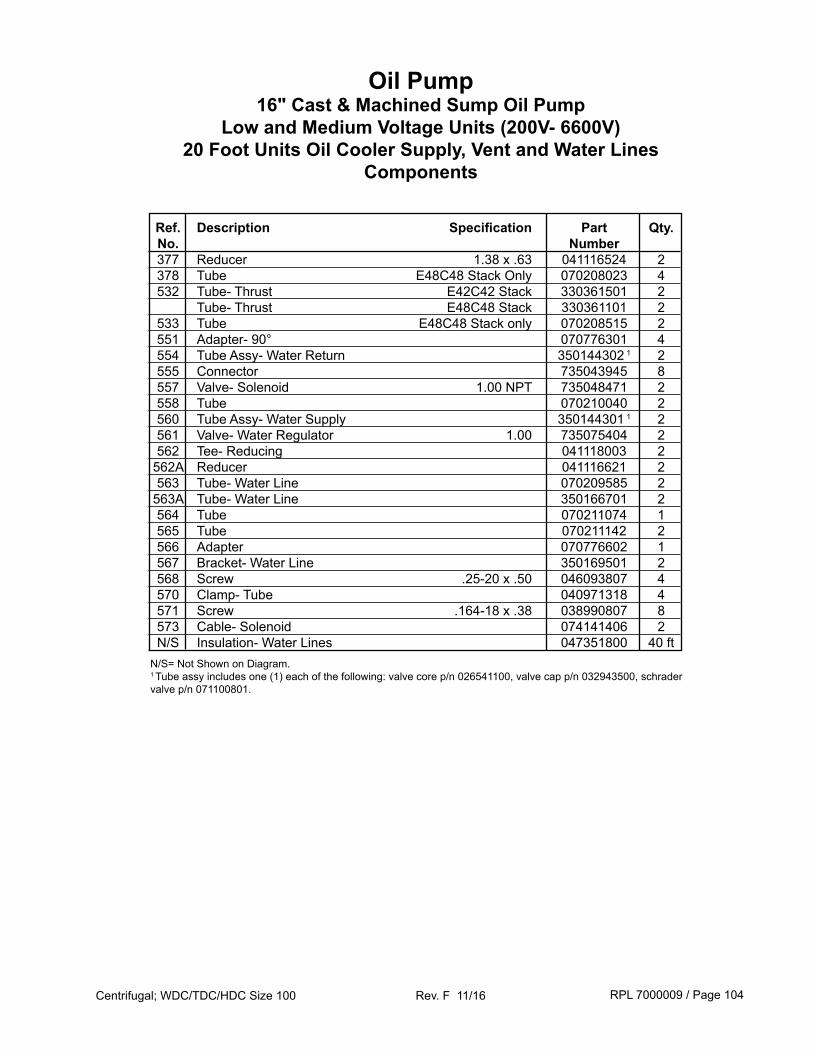
RPL 7000009 / Page 104Centrifugal; WDC/TDC/HDC Size 100 Rev. F 11/16
Ref. Description Specification Part Qty. No. Number 377 Reducer 1.38 x .63 041116524 2 378 Tube E48C48 Stack Only 070208023 4 532 Tube- Thrust E42C42 Stack 330361501 2 Tube- Thrust E48C48 Stack 330361101 2 533 Tube E48C48 Stack only 070208515 2 551 Adapter- 90° 070776301 4 554 Tube Assy- Water Return 350144302 1 2 555 Connector 735043945 8 557 Valve- Solenoid 1.00 NPT 735048471 2 558 Tube 070210040 2 560 Tube Assy- Water Supply 350144301 1 2 561 Valve- Water Regulator 1.00 735075404 2 562 Tee- Reducing 041118003 2 562A Reducer 041116621 2 563 Tube- Water Line 070209585 2 563A Tube- Water Line 350166701 2 564 Tube 070211074 1 565 Tube 070211142 2 566 Adapter 070776602 1 567 Bracket- Water Line 350169501 2 568 Screw .25-20 x .50 046093807 4 570 Clamp- Tube 040971318 4 571 Screw .164-18 x .38 038990807 8 573 Cable- Solenoid 074141406 2 N/S Insulation- Water Lines 047351800 40 ftN/S= Not Shown on Diagram.1 Tube assy includes one (1) each of the following: valve core p/n 026541100, valve cap p/n 032943500, schrader valve p/n 071100801.
Oil Pump16" Cast & Machined Sump Oil Pump
Low and Medium Voltage Units (200V- 6600V)20 Foot Units Oil Cooler Supply, Vent and Water Lines
Components
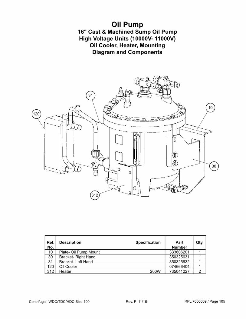
RPL 7000009 / Page 105Centrifugal; WDC/TDC/HDC Size 100 Rev. F 11/16
Oil Pump16" Cast & Machined Sump Oil Pump High Voltage Units (10000V- 11000V)
Oil Cooler, Heater, MountingDiagram and Components
120
Ref. Description Specification Part Qty. No. Number 10 Plate- Oil Pump Mount 333606201 1 30 Bracket- Right Hand 350325631 1 31 Bracket- Left Hand 350325632 1 120 Oil Cooler 074666404 1 312 Heater 200W 735041227 2
31
10
30
312
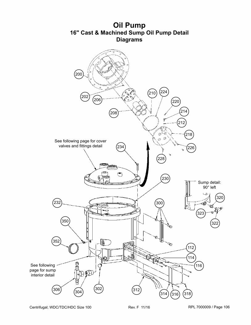
RPL 7000009 / Page 106Centrifugal; WDC/TDC/HDC Size 100 Rev. F 11/16
Oil Pump16" Cast & Machined Sump Oil Pump Detail
Diagrams
234
230
232
350
352
See following page for sump interior detail
306 304302 312
316314 318
116
114
112
300
See following page for cover valves and fittings detail 226
228
218
212
214
220
224210
208
206202
200
Sump detail: 90° left
320
322
323
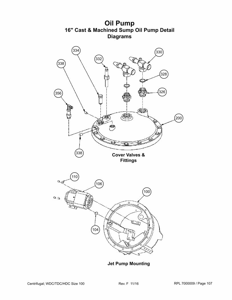
RPL 7000009 / Page 107Centrifugal; WDC/TDC/HDC Size 100 Rev. F 11/16
Oil Pump16" Cast & Machined Sump Oil Pump Detail
Diagrams
338 Cover Valves & Fittings
200
326
328
330
356
332338
334
Jet Pump Mounting
110
106
104
100
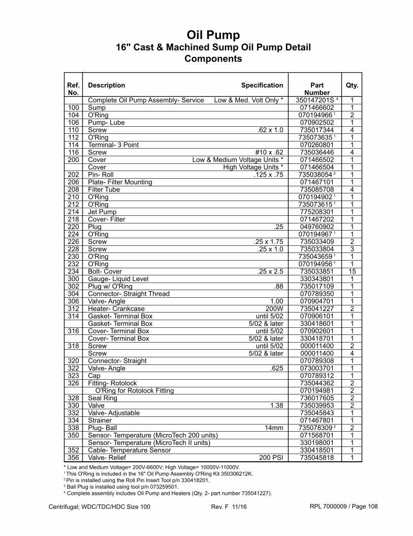
RPL 7000009 / Page 108Centrifugal; WDC/TDC/HDC Size 100 Rev. F 11/16
Ref. Description Specification Part Qty. No. Number Complete Oil Pump Assembly- Service Low & Med. Volt Only * 350147201S 4 1 100 Sump 071466602 1 104 O'Ring 070194966 1 2 106 Pump- Lube 070902502 1 110 Screw .62 x 1.0 735017344 4 112 O'Ring 735073635 1 1 114 Terminal- 3 Point 070260801 1 116 Screw #10 x .62 735036446 4 200 Cover Low & Medium Voltage Units * 071466502 1 Cover High Voltage Units * 071466504 1 202 Pin- Roll .125 x .75 735038054 2 1 206 Plate- Filter Mounting 071467101 1 208 Filter Tube 735085708 4 210 O'Ring 070194902 1 1 212 O'Ring 735073615 1 1 214 Jet Pump 775208301 1 218 Cover- Filter 071467202 1 220 Plug .25 049760902 1 224 O'Ring 070194967 1 1 226 Screw .25 x 1.75 735033409 2 228 Screw .25 x 1.0 735033804 3 230 O'Ring 735043659 1 1 232 O'Ring 070194956 1 1 234 Bolt- Cover .25 x 2.5 735033851 15 300 Gauge- Liquid Level 330343801 1 302 Plug w/ O'Ring .88 735017109 1 304 Connector- Straight Thread 070789350 1 306 Valve- Angle 1.00 070904701 1 312 Heater- Crankcase 200W 735041227 2 314 Gasket- Terminal Box until 5/02 070906101 1 Gasket- Terminal Box 5/02 & later 330418601 1 316 Cover- Terminal Box until 5/02 070902601 1 Cover- Terminal Box 5/02 & later 330418701 1 318 Screw until 5/02 000011400 2 Screw 5/02 & later 000011400 4 320 Connector- Straight 070789308 1 322 Valve- Angle .625 073003701 1 323 Cap 070789312 1 326 Fitting- Rotolock 735044362 2 O'Ring for Rotolock Fitting 070194981 2 328 Seal Ring 736017605 2 330 Valve 1.38 735039953 2 332 Valve- Adjustable 735045843 1 334 Strainer 071467801 1 338 Plug- Ball 14mm 735078309 3 2 350 Sensor- Temperature (MicroTech 200 units) 071568701 1 Sensor- Temperature (MicroTech II units) 330198001 1 352 Cable- Temperature Sensor 330418501 1 356 Valve- Relief 200 PSI 735045818 1* Low and Medium Voltage= 200V-6600V; High Voltage= 10000V-11000V.1 This O'Ring is included in the 16" Oil Pump Assembly O'Ring Kit 350306212K.2 Pin is installed using the Roll Pin Insert Tool p/n 330418201.3 Ball Plug is installed using tool p/n 073259501.4 Complete assembly includes Oil Pump and Heaters (Qty. 2- part number 735041227).
Oil Pump16" Cast & Machined Sump Oil Pump Detail
Components
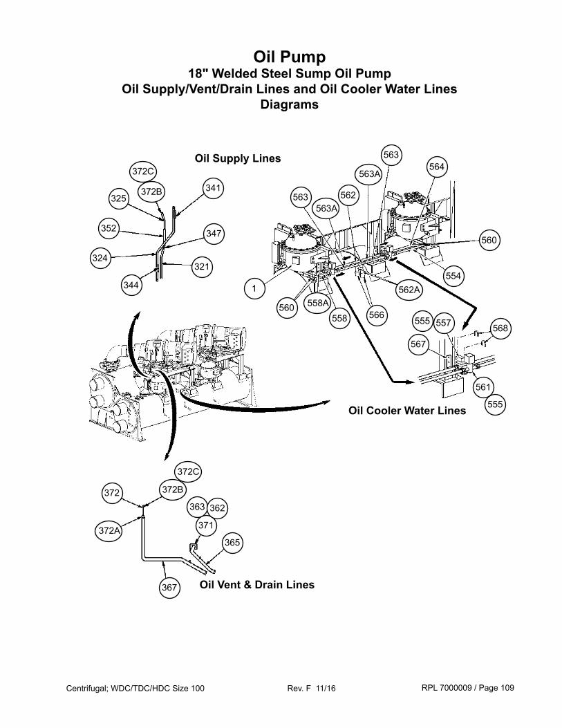
RPL 7000009 / Page 109Centrifugal; WDC/TDC/HDC Size 100 Rev. F 11/16
Oil Pump18" Welded Steel Sump Oil Pump
Oil Supply/Vent/Drain Lines and Oil Cooler Water LinesDiagrams
371
363
Oil Vent & Drain Lines
Oil Supply Lines
Oil Cooler Water Lines
341
372
344
347
367
365372A
321324
362
352
325
372B
372C
372B
372C
554
555
568
561
567
557555
562A
563A
563A
558A
560
1
560
562563
563564
566558
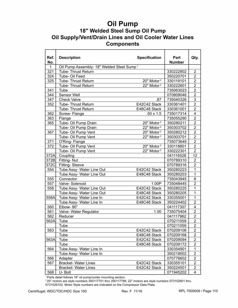
RPL 7000009 / Page 110Centrifugal; WDC/TDC/HDC Size 100 Rev. F 11/16
Oil Pump18" Welded Steel Sump Oil Pump
Oil Supply/Vent/Drain Lines and Oil Cooler Water LinesComponents
Ref. Description Specification Part Qty. No. Number 1 Oil Pump Assembly- 18" Welded Steel Sump 1
321 Tube- Thrust Return 330222802 2 324 Tube- Oil Feed 350220701 2 325 Tube- Thrust Return 20" Motor 2 330119101 2 Tube- Thrust Return 22" Motor 2 330222601 2 341 Tube 735063023 2 344 Sensor Well 070809046 2 347 Check Valve .87 735040326 3 352 Tube- Thrust Return E42C42 Stack 330361401 2 Tube- Thrust Return E48C48 Stack 330361001 2 362 Screw- Flange .50 x 1.5 735017314 4 363 Flange 735055290 2 365 Tube- Oil Pump Drain 20" Motor 2 350280211 2 Tube- Oil Pump Drain 22" Motor 2 350303702 2 367 Tube- Oil Pump Vent 20" Motor 2 350280212 2 Tube- Oil Pump Vent 22" Motor 2 350303701 2 371 O'Ring- Flange 735073649 2 372 Tube- Oil Pump Vent 20" Motor 2 330118801 2 Tube- Oil Pump Vent 22" Motor 2 330222301 2 372A Coupling 041116528 12 372B Fitting- Nut 070789310 2 372C Fitting- Sleeve 070789316 2 554 Tube Assy- Water Line Out E42C42 Stack 350280223 1 Tube Assy- Water Line Out E48C48 Stack 350280203 1 555 Connector 735043945 8 557 Valve- Solenoid 1.00P 735048445 2 558 Tube Assy- Water Line Out E42C42 Stack 350280225 1 Tube Assy- Water Line Out E48C48 Stack 350280205 1 558A Tube Assy- Water Line In E42C42 Stack 330355001 1 Tube Assy- Water Line In E48C48 Stack 350224402 2 560 Elbow- 90° 041117307 4 561 Valve- Water Regulator 1.00 735075404 2 562 Reducer 041117962 2 562A Tube 070211059 2 Tube 070211059 2 563 Tube E42C42 Stack 070209106 2 Tube E48C48 Stack 070209168 2 563A Tube E42C42 Stack 070209094 2 Tube E48C48 Stack 070209172 2 564 Tube Assy- Water Line In 330354901 1 Tube Assy- Water Line In 350218002 2 566 Adapter 070776602 2 567 Bracket- Water Lines E42C42 Stack 330355101 2 Bracket- Water Lines E42C42 Stack 350224501 2 568 U- Bolt 071945202 41 Parts detail follows 18" oil pump/cooler mounting section.2 20" motors are style numbers 350117701 thru 350117786; 22" motors are style numbers 073102601 thru 0731026102. Motor Style numbers are indicated on the Compressor Data Plate.
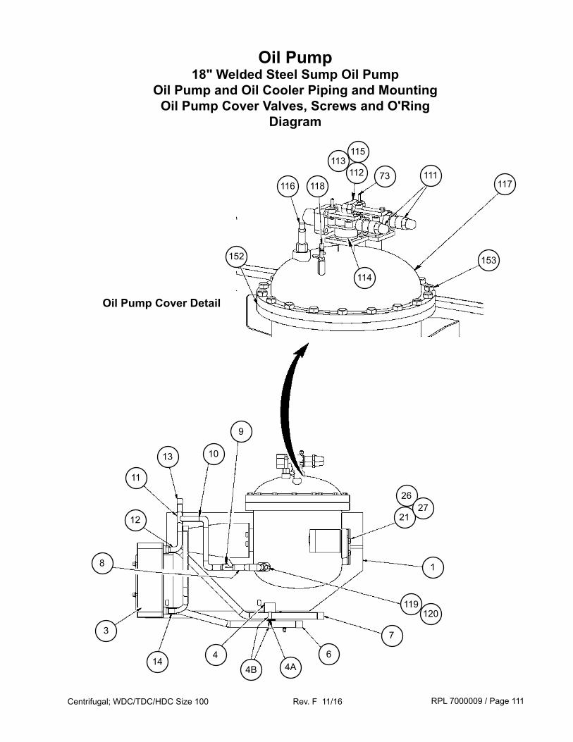
RPL 7000009 / Page 111Centrifugal; WDC/TDC/HDC Size 100 Rev. F 11/16
Oil Pump18" Welded Steel Sump Oil Pump
Oil Pump and Oil Cooler Piping and MountingOil Pump Cover Valves, Screws and O'Ring
Diagram
152
111
12
11
3
118116 117
153
73112113
115
114
13
8
10
9
21
1
7
64A4B
144
2627
119120
Oil Pump Cover Detail
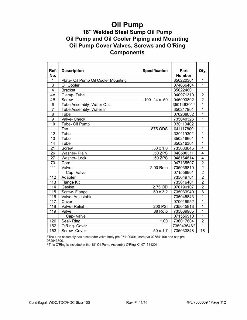
RPL 7000009 / Page 112Centrifugal; WDC/TDC/HDC Size 100 Rev. F 11/16
Ref. Description Specification Part Qty. No. Number 1 Plate- Oil Pump Oil Cooler Mounting 350220301 1 3 Oil Cooler 074666404 1 4 Bracket 350224601 1 4A Clamp- Tube 040971310 2 4B Screw .190- 24 x .50 046093802 2 6 Tube Assembly- Water Out 350146301 1 1 7 Tube Assembly- Water In 350217901 1 8 Tube 070208032 1 9 Valve- Check 735040326 1 10 Tube- Oil Pump 330119402 1 11 Tee .875 ODS 041117809 1 12 Tube 330119302 1 13 Tube 350216601 1 14 Tube 350216301 1 21 Screw .50 x 1.0 735033845 4 26 Washer- Plain .50 ZPS 040500311 4 27 Washer- Lock .50 ZPS 048164814 4 73 Core 047135507 2 111 Valve 2.00 Roto 735039810 2 Cap- Valve 071556901 2 112 Adapter 735049701 2 113 Flange Kit 735016401 2 114 Gasket 2.75 OD 070199107 2 115 Screw- Flange .50 x 3.2 735033940 8 116 Valve- Adjustable 735045843 1 117 Cover 070019952 1 118 Valve- Relief 200 PSI 735045818 1 119 Valve .88 Roto 735039965 1 Cap- Valve 071556910 1 120 Seal- Ring 1.00 736017604 2 152 O'Ring- Cover 735043646 2 1 153 Screw- Cover .50 x 1.7 735033848 181 The tube assembly has a schrader valve body p/n 071100801, core p/n 026541100 and cap p/n 032943500.2 This O'Ring is included in the 18" Oil Pump Assembly O'Ring Kit 071541201.
Oil Pump18" Welded Steel Sump Oil Pump
Oil Pump and Oil Cooler Piping and MountingOil Pump Cover Valves, Screws and O'Ring
Components
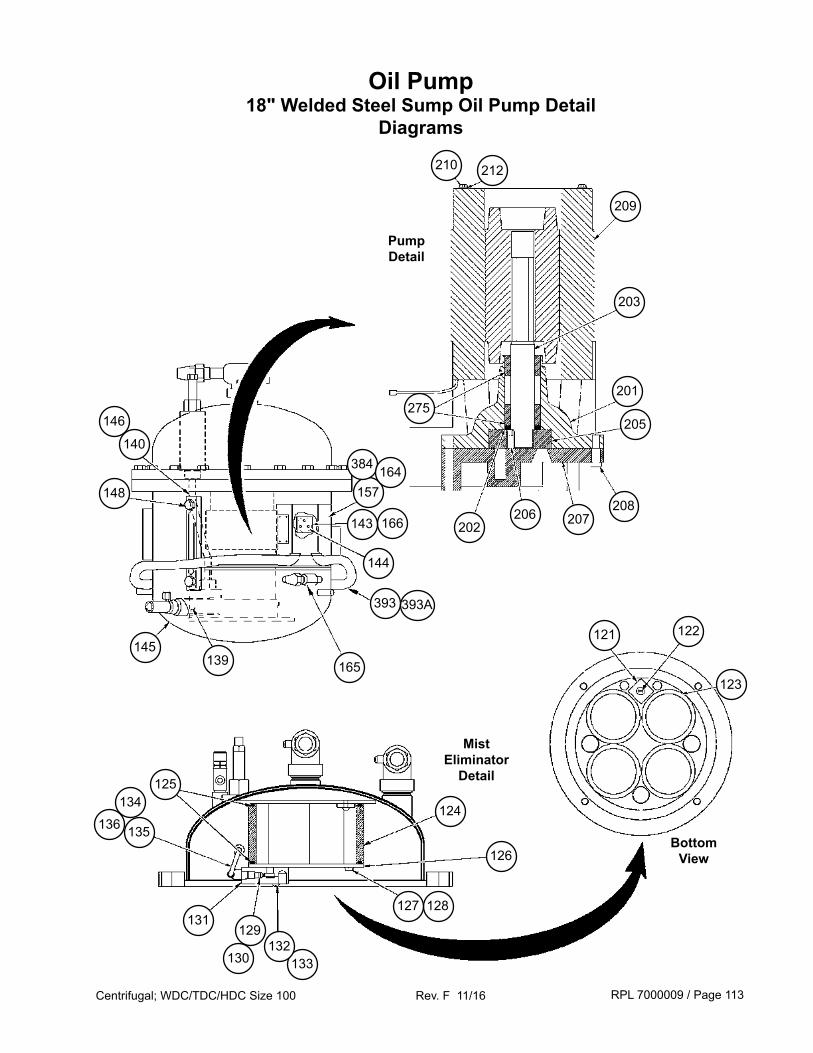
RPL 7000009 / Page 113Centrifugal; WDC/TDC/HDC Size 100 Rev. F 11/16
209
203
210 212
201
205
208202 207206
275
157
384
393
165
148
146
140
145
125
135
139
136
134
131129
133130132
128127
124
121
123
122
Oil Pump18" Welded Steel Sump Oil Pump Detail
Diagrams
126
164
166143
144
Pump Detail
Mist Eliminator
Detail
Bottom View
393A
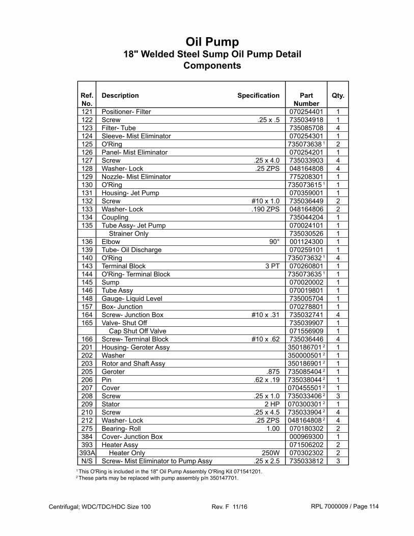
RPL 7000009 / Page 114Centrifugal; WDC/TDC/HDC Size 100 Rev. F 11/16
Ref. Description Specification Part Qty. No. Number 121 Positioner- Filter 070254401 1 122 Screw .25 x .5 735034918 1 123 Filter- Tube 735085708 4 124 Sleeve- Mist Eliminator 070254301 1 125 O'Ring 735073638 1 2 126 Panel- Mist Eliminator 070254201 1 127 Screw .25 x 4.0 735033903 4 128 Washer- Lock .25 ZPS 048164808 4 129 Nozzle- Mist Eliminator 775208301 1 130 O'Ring 735073615 1 1 131 Housing- Jet Pump 070359001 1 132 Screw #10 x 1.0 735036449 2 133 Washer- Lock .190 ZPS 048164806 2 134 Coupling 735044204 1 135 Tube Assy- Jet Pump 070024101 1 Strainer Only 735030526 1 136 Elbow 90° 001124300 1 139 Tube- Oil Discharge 070259101 1 140 O'Ring 735073632 1 4 143 Terminal Block 3 PT 070260801 1 144 O'Ring- Terminal Block 735073635 1 1 145 Sump 070020002 1 146 Tube Assy 070019801 1 148 Gauge- Liquid Level 735005704 1 157 Box- Junction 070278801 1 164 Screw- Junction Box #10 x .31 735032741 4 165 Valve- Shut Off 735039907 1 Cap Shut Off Valve 071556909 1 166 Screw- Terminal Block #10 x .62 735036446 4 201 Housing- Geroter Assy 350186701 2 1 202 Washer 350000501 2 1 203 Rotor and Shaft Assy 350186901 2 1 205 Geroter .875 735085404 2 1 206 Pin .62 x .19 735038044 2 1 207 Cover 070455501 2 1 208 Screw .25 x 1.0 735033406 2 3 209 Stator 2 HP 070300301 2 1 210 Screw .25 x 4.5 735033904 2 4 212 Washer- Lock .25 ZPS 048164808 2 4 275 Bearing- Roll 1.00 070180302 2 384 Cover- Junction Box 000969300 1 393 Heater Assy 071506202 2 393A Heater Only 250W 070302302 2 N/S Screw- Mist Eliminator to Pump Assy .25 x 2.5 735033812 3
1 This O'Ring is included in the 18" Oil Pump Assembly O'Ring Kit 071541201.2 These parts may be replaced with pump assembly p/n 350147701.
Oil Pump18" Welded Steel Sump Oil Pump Detail
Components
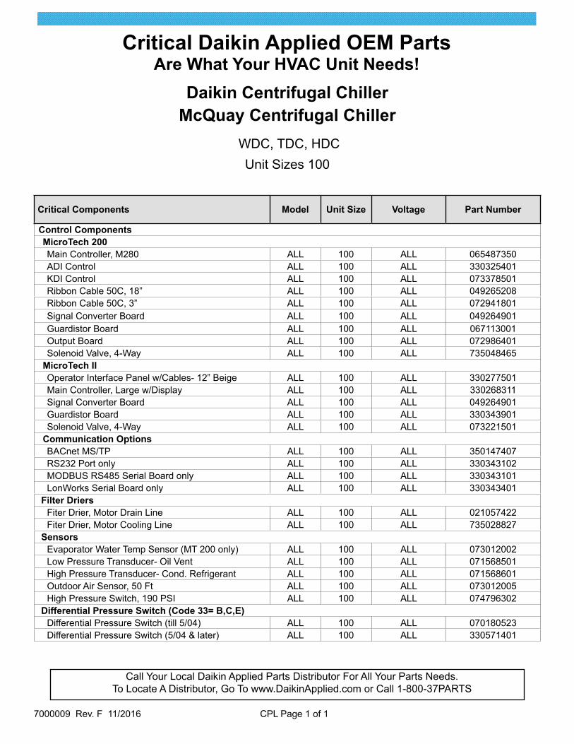
Call Your Local Daikin Applied Parts Distributor For All Your Parts Needs.To Locate A Distributor, Go To www.DaikinApplied.com or Call 1-800-37PARTS
Critical Daikin Applied OEM PartsAre What Your HVAC Unit Needs!
7000009 Rev. F 11/2016 CPL Page 1 of 1
Daikin Centrifugal ChillerMcQuay Centrifugal Chiller
WDC, TDC, HDCUnit Sizes 100
Critical Components Model Unit Size Voltage Part Number
Control ComponentsMicroTech 200Main Controller, M280 ALL 100 ALL 065487350ADI Control ALL 100 ALL 330325401KDI Control ALL 100 ALL 073378501Ribbon Cable 50C, 18” ALL 100 ALL 049265208Ribbon Cable 50C, 3” ALL 100 ALL 072941801Signal Converter Board ALL 100 ALL 049264901Guardistor Board ALL 100 ALL 067113001Output Board ALL 100 ALL 072986401Solenoid Valve, 4-Way ALL 100 ALL 735048465
MicroTech IIOperator Interface Panel w/Cables- 12” Beige ALL 100 ALL 330277501Main Controller, Large w/Display ALL 100 ALL 330268311Signal Converter Board ALL 100 ALL 049264901Guardistor Board ALL 100 ALL 330343901Solenoid Valve, 4-Way ALL 100 ALL 073221501
Communication OptionsBACnet MS/TP ALL 100 ALL 350147407RS232 Port only ALL 100 ALL 330343102MODBUS RS485 Serial Board only ALL 100 ALL 330343101LonWorks Serial Board only ALL 100 ALL 330343401
Filter DriersFiter Drier, Motor Drain Line ALL 100 ALL 021057422Fiter Drier, Motor Cooling Line ALL 100 ALL 735028827
SensorsEvaporator Water Temp Sensor (MT 200 only) ALL 100 ALL 073012002Low Pressure Transducer- Oil Vent ALL 100 ALL 071568501High Pressure Transducer- Cond. Refrigerant ALL 100 ALL 071568601Outdoor Air Sensor, 50 Ft ALL 100 ALL 073012005High Pressure Switch, 190 PSI ALL 100 ALL 074796302
Differential Pressure Switch (Code 33= B,C,E)Differential Pressure Switch (till 5/04) ALL 100 ALL 070180523Differential Pressure Switch (5/04 & later) ALL 100 ALL 330571401