Embed Size (px)
Citation preview
RTI TEST REPORT
Aerosol Systems Test:
Viking Life-Saving Equipment
Prepared by:
Andrew Dart
RTI International
P.O. Box 12194
Research Triangle Park, NC 27709
(919) 541-7279
RTI Project No. 0216052
Task Order 1
Prepared for:
Dorthe Torngren la Cour
PPE Fire Engineering Manager
Viking Life Saving Equipment
Saedding Ringvej 13, 6710 Esbjerg V Denmark
October 5, 2017
A-1
1. Introduction
Under contract with the Viking Life-Saving Equipment, RTI International (RTI) evaluated the
aerosol penetration of two fire fighter protective ensembles. The evaluation consisted of head-to-
head tests of two fire fighter turn out systems for a total of two system-level human-use aerosol
challenge tests. The tests used non-toxic aerosol simulants and were conducted in accordance
with an approved RTI human-use protocol.
The objective of the tests was to measure and compare the aerosol deposition velocities for areas
of the test participants’ skin after wearing the protective ensembles in an aerosol exposure wind
tunnel.
Descriptions of the garment systems and the test matrix are presented in Sections 2 and 3,
respectively. Section 4 presents the test results and Section 5 provides a summary discussion.
Appendix A describes the test facility and procedures used for the tests. Appendix B contains
the donning and doffing sequences. Appendix C presents the complete test conditions and
aerosol deposition velocity for each sample and for each test run.
2. Test Garments
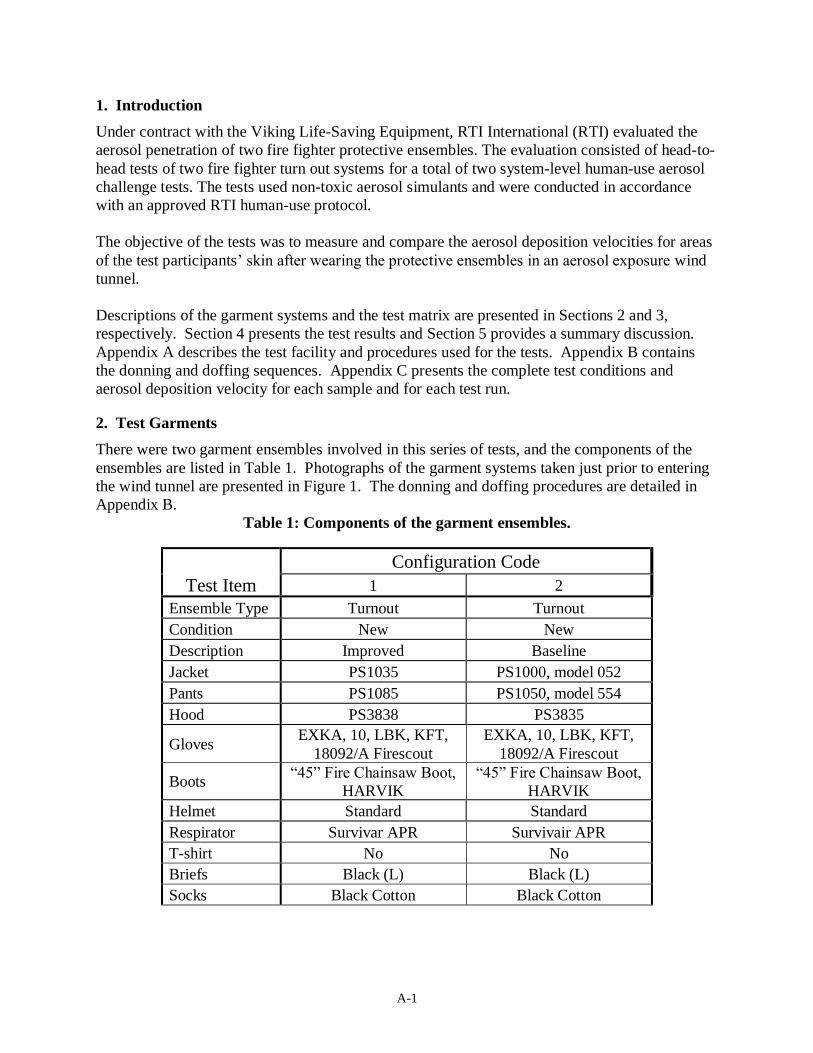
There were two garment ensembles involved in this series of tests, and the components of the
ensembles are listed in Table 1. Photographs of the garment systems taken just prior to entering
the wind tunnel are presented in Figure 1. The donning and doffing procedures are detailed in
Appendix B.
Table 1: Components of the garment ensembles.
Test Item
Configuration Code
1 2
Ensemble Type Turnout Turnout
Condition New New
Description Improved Baseline
Jacket PS1035 PS1000, model 052
Pants PS1085 PS1050, model 554
Hood PS3838 PS3835
Gloves EXKA, 10, LBK, KFT,
18092/A Firescout
EXKA, 10, LBK, KFT,
18092/A Firescout
Boots “45” Fire Chainsaw Boot,
HARVIK
“45” Fire Chainsaw Boot,
HARVIK
Helmet Standard Standard
Respirator Survivar APR Survivair APR
T-shirt No No
Briefs Black (L) Black (L)
Socks Black Cotton Black Cotton
A-2
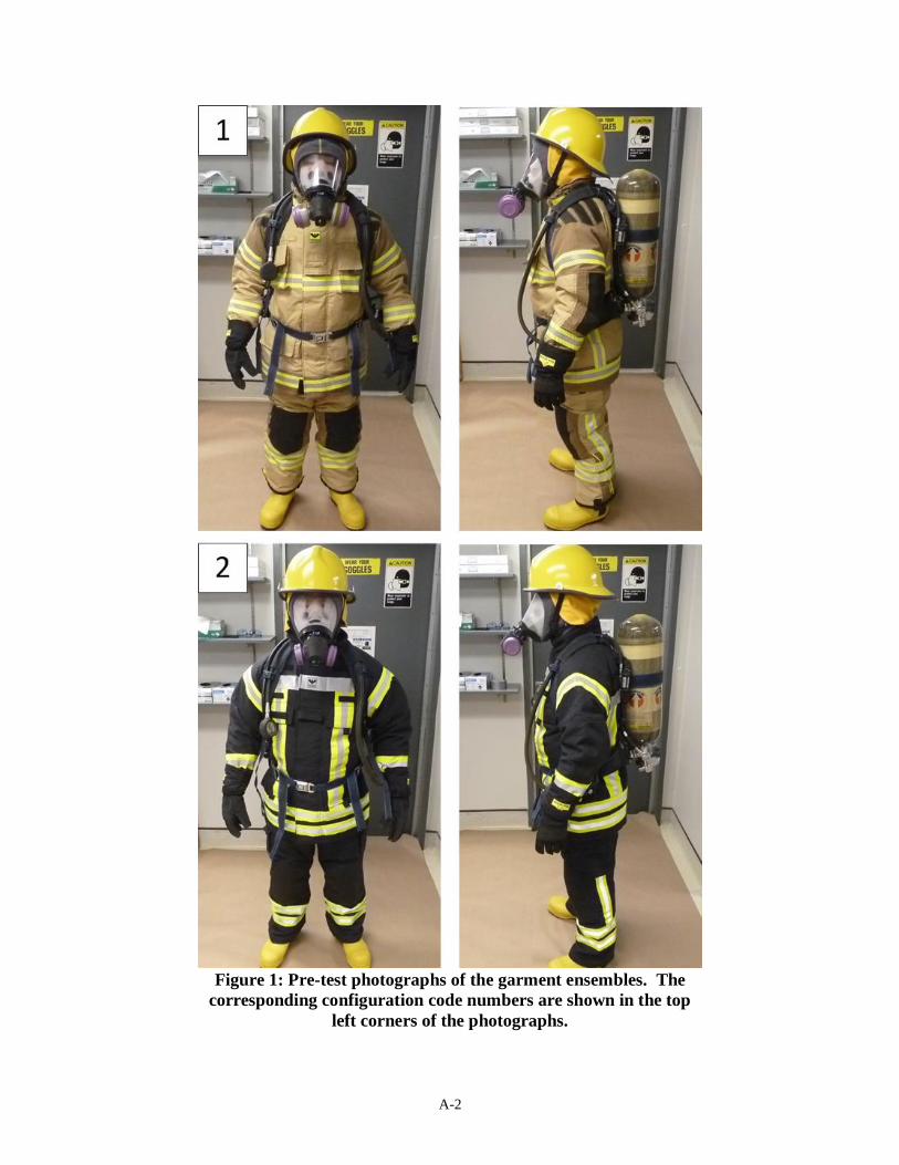
Figure 1: Pre-test photographs of the garment ensembles. The
corresponding configuration code numbers are shown in the top
left corners of the photographs.
A-3
3. Test Series
Each of the garment ensembles listed above was tested once. The test sequence was chosen to
evaluate configuration one prior to configuration two. Additionally, each test was performed by
the same test participant to mitigate the risk of introducing bias. Table 2 presents a summary of
the test series including the test participant(s).
4. Results
Complete results from the garment tests are presented in Appendix C. The results are presented
as the deposition velocity for each skin sampling area for each test. Also included are the test
conditions (T, RH, and wind speed), the aerosol CT, and the background and post-test
fluorescence values for each skin sampling area.
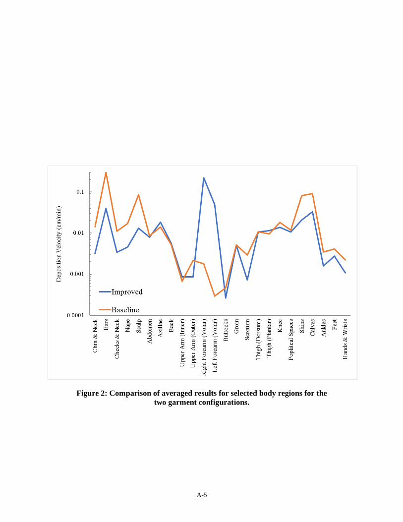
Table 3 summarizes the results for each garment configuration. In this table, results have been
averaged for selected body areas and for each test, providing a convenient basis for comparison
of the overall garment system performance. Figure 2 presents a graphical summary of the results
for selected body regions for each garment system. Table 4 shows the results for each of the 50
skin sampling locations for each test. The locations of each skin sampling area are shown
schematically in Appendix A.
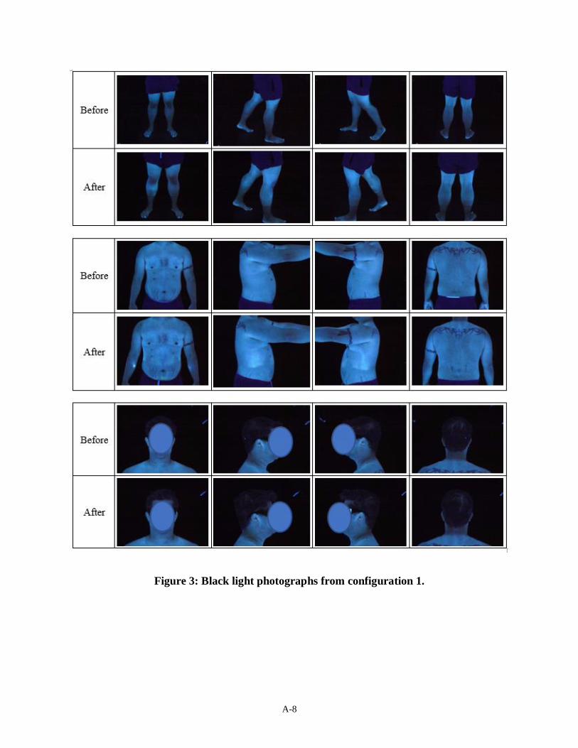
Representative black light photographs from each configuration are shown in Figures 3 and 4. In
the black light photographs, light blue coloration indicates a relatively light aerosol deposition
while yellow coloration indicates relatively heavy aerosol deposition. Some areas of the skin --
such as back of the elbows, the soles of the feet, palms, and toe and finger nails -- have a bright
natural fluorescence even in the absence of aerosol deposits. Therefore, brightness on the soles of
the feet and on the palms of the hands does not necessarily indicate a problem with the footwear
or glove systems.
In regions of moderate to heavy aerosol deposition on the skin, circular areas are often visible
where the skin-rinse samples were obtained. These circular areas provide a convenient basis for
judging the level of deposition on the surrounding skin (i.e., the circular areas are relatively clean
in comparison to the surrounding aerosol deposits).
When comparing two or more pictures, note the lighting and the camera’s exposure level may
not necessarily be identical between photos or between tests. Attempts were made to maintain
consistency, but conditions nevertheless vary from photo to photo and test to test. The black light
photographs are best used to show possible areas of aerosol infiltration, the general pattern of
aerosol deposition, and relative intensities of deposition. The photographs compliment and aid in
interpretation of the quantitative analysis that is performed on each sample.
A-4
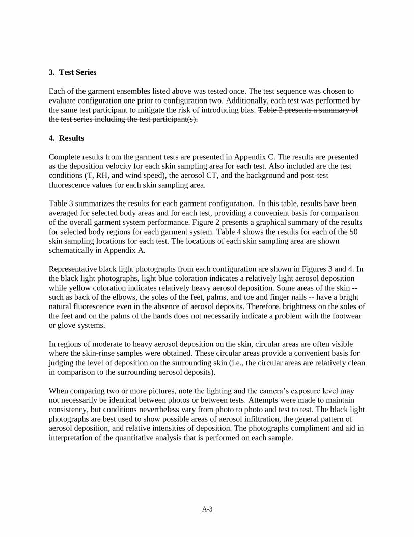
Table 2: Summary of aerosol deposition velocity results
(cm/min) for garment configurations 1 and 2.
Body Region
Configuration Code
1 2
All (simple average) 0.009 0.030
All except head, neck, ear 0.009 0.028
Chin & Neck 0.003 0.014
Ears 0.040 0.298
Cheeks & Neck 0.003 0.011
Nape 0.005 0.017
Scalp 0.013 0.086
Abdomen 0.008 0.009
Axillae 0.019 0.014
Back 0.006 0.005
Upper Arm (Inner) 0.001 0.001
Upper Arm (Outer) 0.001 0.002
Right Forearm (Volar) 0.221 0.002
Left Forearm (Volar) 0.049 0.000
Buttocks 0.000 0.000
Groin 0.005 0.005
Scrotum 0.001 0.003
Thigh (Dorsum) 0.011 0.011
Thigh (Plantar) 0.012 0.010
Knee 0.014 0.018
Popliteal Spaces 0.011 0.012
Shins 0.021 0.082
Calves 0.033 0.090
Ankles 0.002 0.003
Feet 0.003 0.004
Hands & Wrists 0.001 0.002
Chin & Neck 0.003 0.014
Ears 0.040 0.298
+
A-5
Figure 2: Comparison of averaged results for selected body regions for the
two garment configurations.
A-6
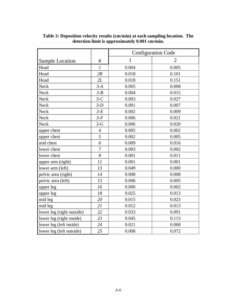
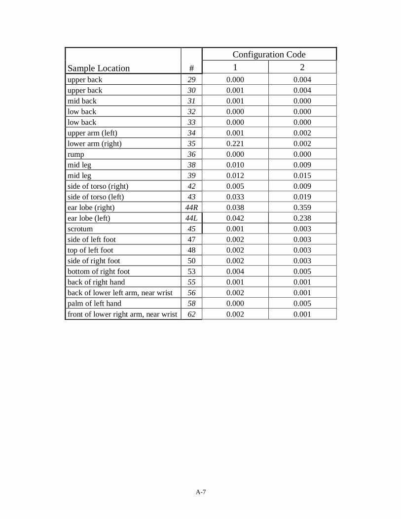
Table 3: Deposition velocity results (cm/min) at each sampling location. The
detection limit is approximately 0.001 cm/min.
Sample Location #
Configuration Code
1 2
Head 1 0.004 0.005
Head 2R 0.018 0.101
Head 2L 0.018 0.151
Neck 3-A 0.005 0.008
Neck 3-B 0.004 0.015
Neck 3-C 0.003 0.027
Neck 3-D 0.001 0.007
Neck 3-E 0.002 0.009
Neck 3-F 0.006 0.021
Neck 3-G 0.006 0.020
upper chest 4 0.005 0.002
upper chest 5 0.002 0.005
mid chest 6 0.009 0.016
lower chest 7 0.003 0.002
lower chest 8 0.001 0.011
upper arm (right) 11 0.001 0.001
lower arm (left) 13 0.049 0.000
pelvic area (right) 14 0.008 0.008
pelvic area (left) 15 0.006 0.005
upper leg 16 0.000 0.002
upper leg 18 0.025 0.013
mid leg 20 0.015 0.023
mid leg 21 0.012 0.013
lower leg (right outside) 22 0.033 0.091
lower leg (right inside) 23 0.045 0.113
lower leg (left inside) 24 0.021 0.068
lower leg (left outside) 25 0.008 0.072
A-7
Sample Location #
Configuration Code
1 2
upper back 29 0.000 0.004
upper back 30 0.001 0.004
mid back 31 0.001 0.000
low back 32 0.000 0.000
low back 33 0.000 0.000
upper arm (left) 34 0.001 0.002
lower arm (right) 35 0.221 0.002
rump 36 0.000 0.000
mid leg 38 0.010 0.009
mid leg 39 0.012 0.015
side of torso (right) 42 0.005 0.009
side of torso (left) 43 0.033 0.019
ear lobe (right) 44R 0.038 0.359
ear lobe (left) 44L 0.042 0.238
scrotum 45 0.001 0.003
side of left foot 47 0.002 0.003
top of left foot 48 0.002 0.003
side of right foot 50 0.002 0.003
bottom of right foot 53 0.004 0.005
back of right hand 55 0.001 0.001
back of lower left arm, near wrist 56 0.002 0.001
palm of left hand 58 0.000 0.005
front of lower right arm, near wrist 62 0.002 0.001
A-8
Figure 3: Black light photographs from configuration 1.
A-9
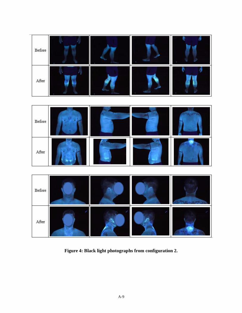
Figure 4: Black light photographs from configuration 2.
A-10
5. Discussion of Results
The measured aerosol deposition velocities were generally lower for configuration 1 as
compared to configuration 2. The hot spots on the subject’s forearms in configuration 1
increased the overall average by nearly 50%. Aerosol penetrating the inner sleeve would deposit
on the forearm in this location. Configuration 2 showed a significantly greater amount of
widespread aerosol deposited on the TPs skin than configuration 1.
A-11
Appendix A
SYSTEM-LEVEL AEROSOL CHALLENGE TESTING OF
CHEMICAL PROTECTIVE GARMENTS
1. Introduction
Chemical protective clothing has traditionally been used to protect against threats posed by
hazardous gases and liquids. In addition to these continuing threats, aerosolized chemical and
biological agents also pose threats. Through a series of contracts with DOD, RTI has developed
a full-scale aerosol challenge test for chemical protective clothing. The tests use a non-toxic
fluorescently-tagged aerosol simulant. These methods have been used to evaluate the
performance of military and first-responder protective clothing relative to aerosol protection.
Aerosol penetration of garments is dependent upon many variables. These include the garment’s
fabric and closure properties, the surrounding environment in terms of wind speed and aerosol
concentration, and body motions which can create a bellows effect drawing aerosol particles into
the garment. RTI’s test facility and protocols provide careful control of all these variables.
The overall objective of the tests is to measure the aerosol deposition velocity to areas of the
subject’s skin after wearing one of several chemical protective ensembles in an aerosol exposure
chamber.
2. Facilities
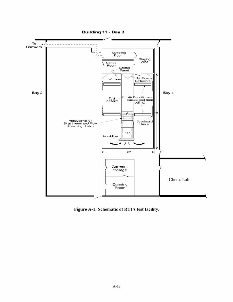
The tests are performed in RTI’s wind tunnel exposure room (Figure A-1). The wind tunnel
contains a 7 ft diameter, 40-hp vane-axial fan centrally located in a 28 ft x 50 ft sealed room.
Wind speeds up to 30 mph may be achieved along the test platform. Upon exiting the test
section, the air freely expands into the room and recirculates back to the fan intake. To facilitate
operations, the test section is mounted on a raised platform providing access from below;
overhead access is also available.
To allow for testing over a range of ambient conditions, the wind tunnel is equipped with
cooling, heating, and humidity controls. Temperatures from approximately 40 to 100o F
A-12
Figure A-1: Schematic of RTI’s test facility.
Chem. Lab
A-13
(4 to 38 C) and relative humidities from approximately 20% to 85% may be achieved. The
ventilation systems of the wind tunnel include a recirculating, high-efficiency filtration system
for the removal of aerosol from the wind tunnel atmosphere and an ambient air purging system.
The wind tunnel is supported by several auxiliary rooms: the control room, which is used to set
the wind speed, temperature and humidity, control aerosol samplers, and maintain direct visual
contact with the test volunteer; the staging and doffing room; isolated rooms for background
sampling and donning; chemistry lab for fluorometric analysis and aerosol preparation; and
locker room facilities where the test volunteers shower after the tests.
3. Test Conditions
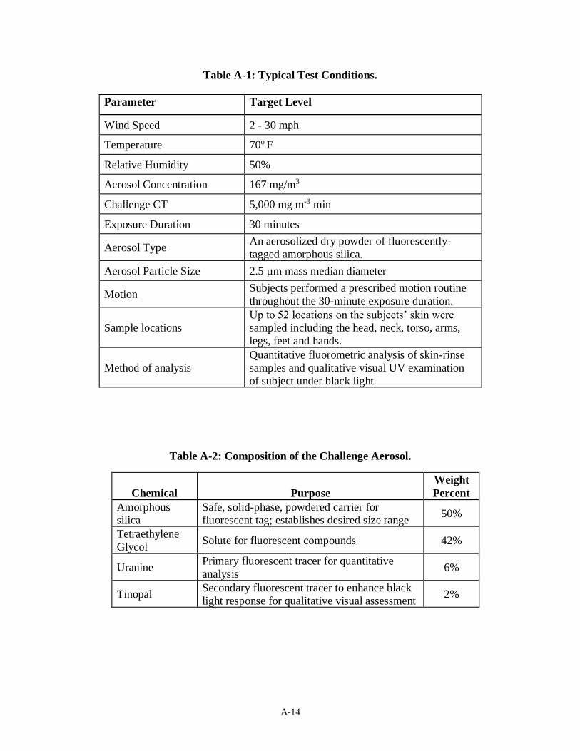
Environmental Conditions: All tests are performed under carefully controlled conditions
(Table A-1). The environmental conditions are set to a wind speed of up to 30 mph (50 km/hr) at
a temperature of 65 - 75 F and a relative humidity of 30 - 60 %. The target challenge aerosol
concentration is 167 mg/m3 which, when combined with the 30-minute exposure duration, yields
a target CT of 5,000 mg m-3 min.
Challenge Aerosol: The challenge aerosol is a dry, solid-phase, fluorescent powder (Table A-
2). The primary constituent is a synthetic, micron-sized, amorphous silica powder (Syloid®).
This powder establishes the particle size of the resultant aerosol and serves as the carrier for the
fluorescent tagging agent. The fluorescent tag is comprised of two fluorescent compounds and a
solute. Uranine is the fluorescent compound used for quantitative analyses. Its uncommon
excitation and emission wavelengths minimize background interferences and lead to low
detection limits. Tinopal is a fluorescent compound that enhances the black light response of the
aerosol deposits. Tetraethylene glycol is a safe, low volatility solute for the two fluorescent
compounds. A blending process is used to dissolve the fluorescent compounds in the
tetraethylene glycol, and then to combine this fluorescent tag with the silica powder. The use of
fluorescent tracers allows accurate measurement of sub-microgram quantities of deposited
aerosol on skin and clothing and minimizes background interference (e.g., from ambient aerosol,
shed clothing fibers and carbon dust).
The resultant aerosol has an aerodynamic mass median diameter (MMD) of approximately 2.5
µm with a geometric standard deviation of approximately 2.6.
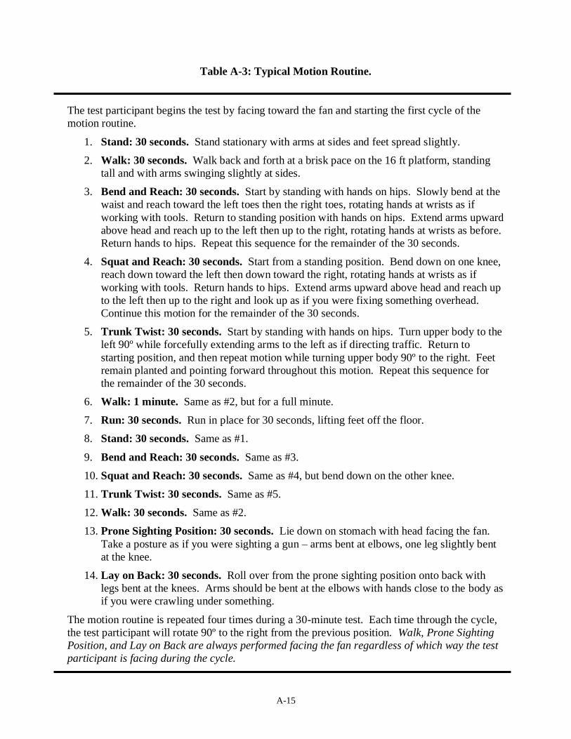
Motion Routine: During each test, the test subject performs a prescribed motion routine. The
routine includes standing, walking, bending, squatting, twisting, running in place, dropping to a
prone position, and rolling over on the back. The motions simulate common field motions and
provide some stress to the garment and to the various closures. Table A-3 outlines a typical
motion routine.
A-14
Table A-1: Typical Test Conditions.
Parameter Target Level
Wind Speed 2 - 30 mph
Temperature 70o F
Relative Humidity 50%
Aerosol Concentration 167 mg/m3
Challenge CT 5,000 mg m-3 min
Exposure Duration 30 minutes
Aerosol Type An aerosolized dry powder of fluorescently-
tagged amorphous silica.
Aerosol Particle Size 2.5 µm mass median diameter
Motion Subjects performed a prescribed motion routine
throughout the 30-minute exposure duration.
Sample locations
Up to 52 locations on the subjects’ skin were
sampled including the head, neck, torso, arms,
legs, feet and hands.
Method of analysis
Quantitative fluorometric analysis of skin-rinse
samples and qualitative visual UV examination
of subject under black light.
Table A-2: Composition of the Challenge Aerosol.
Chemical
Purpose
Weight
Percent
Amorphous
silica
Safe, solid-phase, powdered carrier for
fluorescent tag; establishes desired size range 50%
Tetraethylene
Glycol Solute for fluorescent compounds 42%
Uranine Primary fluorescent tracer for quantitative
analysis 6%
Tinopal Secondary fluorescent tracer to enhance black
light response for qualitative visual assessment 2%
A-15
Table A-3: Typical Motion Routine.
The test participant begins the test by facing toward the fan and starting the first cycle of the
motion routine.
1. Stand: 30 seconds. Stand stationary with arms at sides and feet spread slightly.
2. Walk: 30 seconds. Walk back and forth at a brisk pace on the 16 ft platform, standing
tall and with arms swinging slightly at sides.
3. Bend and Reach: 30 seconds. Start by standing with hands on hips. Slowly bend at the
waist and reach toward the left toes then the right toes, rotating hands at wrists as if
working with tools. Return to standing position with hands on hips. Extend arms upward
above head and reach up to the left then up to the right, rotating hands at wrists as before.
Return hands to hips. Repeat this sequence for the remainder of the 30 seconds.
4. Squat and Reach: 30 seconds. Start from a standing position. Bend down on one knee,
reach down toward the left then down toward the right, rotating hands at wrists as if
working with tools. Return hands to hips. Extend arms upward above head and reach up
to the left then up to the right and look up as if you were fixing something overhead.
Continue this motion for the remainder of the 30 seconds.
5. Trunk Twist: 30 seconds. Start by standing with hands on hips. Turn upper body to the
left 90º while forcefully extending arms to the left as if directing traffic. Return to
starting position, and then repeat motion while turning upper body 90º to the right. Feet
remain planted and pointing forward throughout this motion. Repeat this sequence for
the remainder of the 30 seconds.
6. Walk: 1 minute. Same as #2, but for a full minute.
7. Run: 30 seconds. Run in place for 30 seconds, lifting feet off the floor.
8. Stand: 30 seconds. Same as #1.
9. Bend and Reach: 30 seconds. Same as #3.
10. Squat and Reach: 30 seconds. Same as #4, but bend down on the other knee.
11. Trunk Twist: 30 seconds. Same as #5.
12. Walk: 30 seconds. Same as #2.
13. Prone Sighting Position: 30 seconds. Lie down on stomach with head facing the fan.
Take a posture as if you were sighting a gun – arms bent at elbows, one leg slightly bent
at the knee.
14. Lay on Back: 30 seconds. Roll over from the prone sighting position onto back with
legs bent at the knees. Arms should be bent at the elbows with hands close to the body as
if you were crawling under something.
The motion routine is repeated four times during a 30-minute test. Each time through the cycle,
the test participant will rotate 90º to the right from the previous position. Walk, Prone Sighting
Position, and Lay on Back are always performed facing the fan regardless of which way the test
participant is facing during the cycle.
A-16
4. Donning and Doffing of the Protective Garment
The garment custodian provides the test subject with each item of test clothing in the donning
room. After the subject removes his street clothes, background skin-rinse samples are taken and
immediately analyzed to confirm low background fluorescence levels. The volunteer then dons
the test garments. A test assistant is available to answer any questions about proper donning
procedures. After donning the ensemble, the volunteer walks to the control room of the wind
tunnel. The test operator independently confirms that the proper garments are worn for the
assigned test and that the garments are donned properly.
After the 30 minute exposure in the wind tunnel, the subject exits the chamber into the adjacent
clean doffing room. An 800 cfm HEPA filter air cleaner is used to control any airborne dust
generated from doffing the garment. The test assistant helps the subject doff the garments in a
careful manner to prevent contact of the heavily contaminated outside surface of the garments
with the subject’s skin. After doffing, the subject moves to the sampling room.
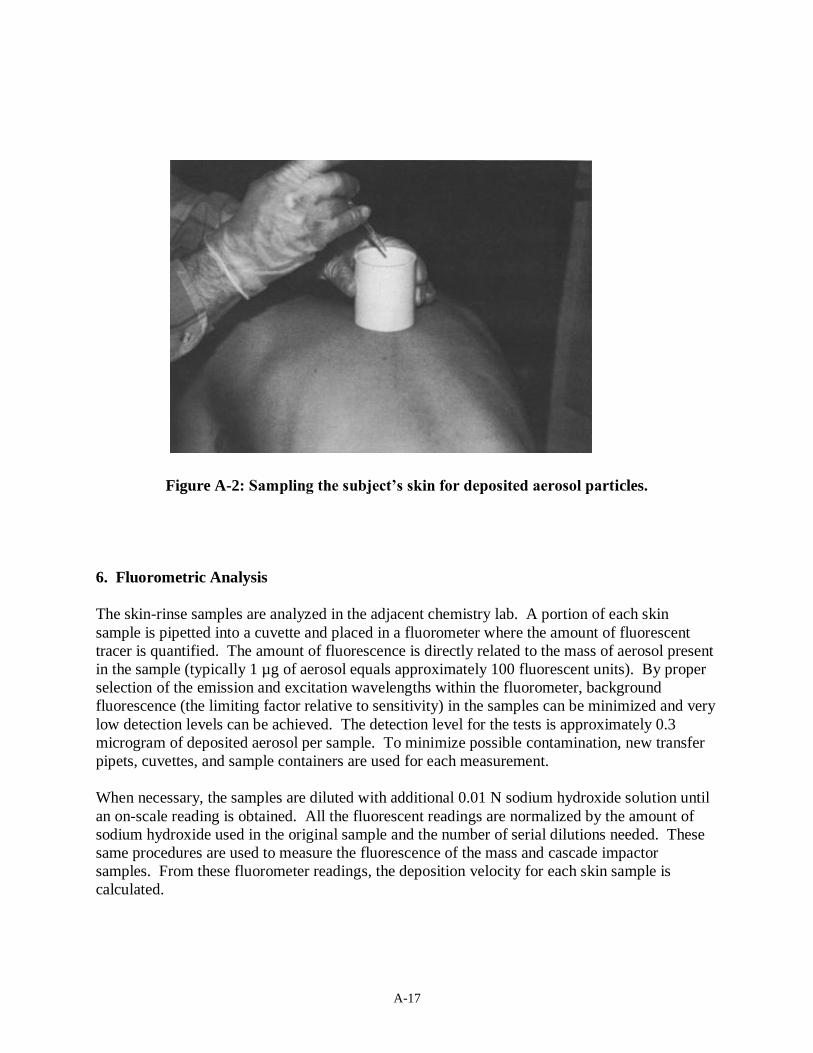
5. Sampling of Deposited Aerosol on the Skin
Aerosol that has deposited on the subject’s skin is extracted by rinsing prescribed areas with a
0.01 N sodium hydroxide solution. Because tetraethylene glycol, uranine and Tinopal are all
water soluble, they readily dissolve into the sodium hydroxide solution. For uranine to fluoresce,
the solution must be basic. The 0.01 N sodium hydroxide solution provides the needed basic pH
and does not cause skin irritation. The extraction is performed by firmly pressing a small PVC
tube against the skin, adding 20 milliliters of 0.01 N sodium hydroxide followed by removal of
the liquid by pipetting into a sample vial (Figure A-2). The solution is washed over the skin for
about 20 seconds and then pipetted into a clean container. This is done for approximately 50
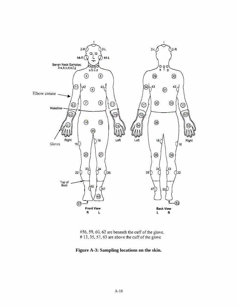
locations on the skin, including the arms, legs, torso, neck, and head (Figure A-3). Different
diameter tubes are used to accommodate the different sized areas of the skin; 1" diameter tubes
are used on narrow or areas of high curvature such as the neck and head, 1-1/2" diameter tubes
used for the arms and 2" tubes used for larger areas such as torso and thighs. (The area of the
sample is taken into account in the data analysis.) To sample the earlobe and scrotum, a series of
three swab samples are taken rather than using the tube method.
Once the skin sampling is completed, the subject is examined under black light and photographs
are taken to document the nature of the deposition. Viewing under black light provides a useful
visual qualitative assessment of the amount of deposition on the skin that often aided in
interpreting the quantitative fluorometric analyses performed in the lab. After the black light
examination, the volunteer’s participation for the day is over and he goes to a nearby locker
room to shower.
A-17
Figure A-2: Sampling the subject’s skin for deposited aerosol particles.
6. Fluorometric Analysis
The skin-rinse samples are analyzed in the adjacent chemistry lab. A portion of each skin
sample is pipetted into a cuvette and placed in a fluorometer where the amount of fluorescent
tracer is quantified. The amount of fluorescence is directly related to the mass of aerosol present
in the sample (typically 1 µg of aerosol equals approximately 100 fluorescent units). By proper
selection of the emission and excitation wavelengths within the fluorometer, background
fluorescence (the limiting factor relative to sensitivity) in the samples can be minimized and very
low detection levels can be achieved. The detection level for the tests is approximately 0.3
microgram of deposited aerosol per sample. To minimize possible contamination, new transfer
pipets, cuvettes, and sample containers are used for each measurement.
When necessary, the samples are diluted with additional 0.01 N sodium hydroxide solution until
an on-scale reading is obtained. All the fluorescent readings are normalized by the amount of
sodium hydroxide used in the original sample and the number of serial dilutions needed. These
same procedures are used to measure the fluorescence of the mass and cascade impactor
samples. From these fluorometer readings, the deposition velocity for each skin sample is
calculated.
A-18
Figure A-3: Sampling locations on the skin.
A-19
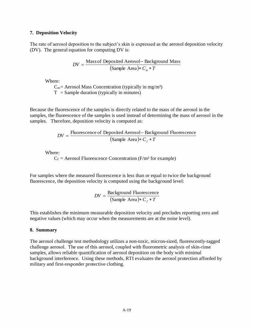
7. Deposition Velocity
The rate of aerosol deposition to the subject’s skin is expressed as the aerosol deposition velocity
(DV). The general equation for computing DV is:
( ) TCDV
m
−=
Area Sample
Mass BackgroundAerosol Deposited of Mass
Where:
Cm = Aerosol Mass Concentration (typically in mg/m³)
T = Sample duration (typically in minutes)
Because the fluorescence of the samples is directly related to the mass of the aerosol in the
samples, the fluorescence of the samples is used instead of determining the mass of aerosol in the
samples. Therefore, deposition velocity is computed as:
( ) TCDV
f
−=
Area Sample
ceFluorescen BackgroundAerosol Deposited of ceFluorescen
Where:
Cf = Aerosol Fluorescence Concentration (F/m³ for example)
For samples where the measured fluorescence is less than or equal to twice the background
fluorescence, the deposition velocity is computed using the background level:
( ) TCDV
f =
Area Sample
ceFluorescen Background
This establishes the minimum measurable deposition velocity and precludes reporting zero and
negative values (which may occur when the measurements are at the noise level).
8. Summary
The aerosol challenge test methodology utilizes a non-toxic, micron-sized, fluorescently-tagged
challenge aerosol. The use of this aerosol, coupled with fluorometric analysis of skin-rinse
samples, allows reliable quantification of aerosol deposition on the body with minimal
background interference. Using these methods, RTI evaluates the aerosol protection afforded by
military and first-responder protective clothing.
B-1
Appendix B
DONNING AND DOFFING PROCEDURES
Donning: all configuration codes
ITEM Donning Instructions
Undergarments Don briefs and cotton socks.
Trousers and Boots
1. Don trousers
2. Secure fly zipper and waist buttons. 3. Position suspenders over shoulders and fasten snap couplers. Trouser length
can be adjusted by raising and lowering suspenders – should fit comfortably along the inseam.
4. Secure waist adjustment tabs. 5. Don turnout boots.
Over boots
1. Don over boots and secure the closures on the. 2. Position leg over the and secure the Velcro straps.
Ear Plugs Don ear plugs.
Coat
1. Don coat so that gloves are outside the sleeve cuff. 2. Close coat zipper slider up to neck, and close outer flap. Make sure zipper
slider is tucked entirely under the outer flap. 3. Make sure the wrist areas (gauntlets) of gloves are completely closed. 4. Fasten the hook and loop sleeve tabs. 5. Make sure all pockets on the coat and trousers are closed.
Fire Scout
Gloves
1. Don gloves
2. Assistant tightens gauntlet by pulling hook and loop strap around wrist and fastening to close.
Survivair Mask
1. Don the mask and secure the harness straps. 2. Don the flash hood over the mask and pull the opening of the hood over the
face piece of the mask. 3. Attach the filter canister(s) to the mask.
B-2
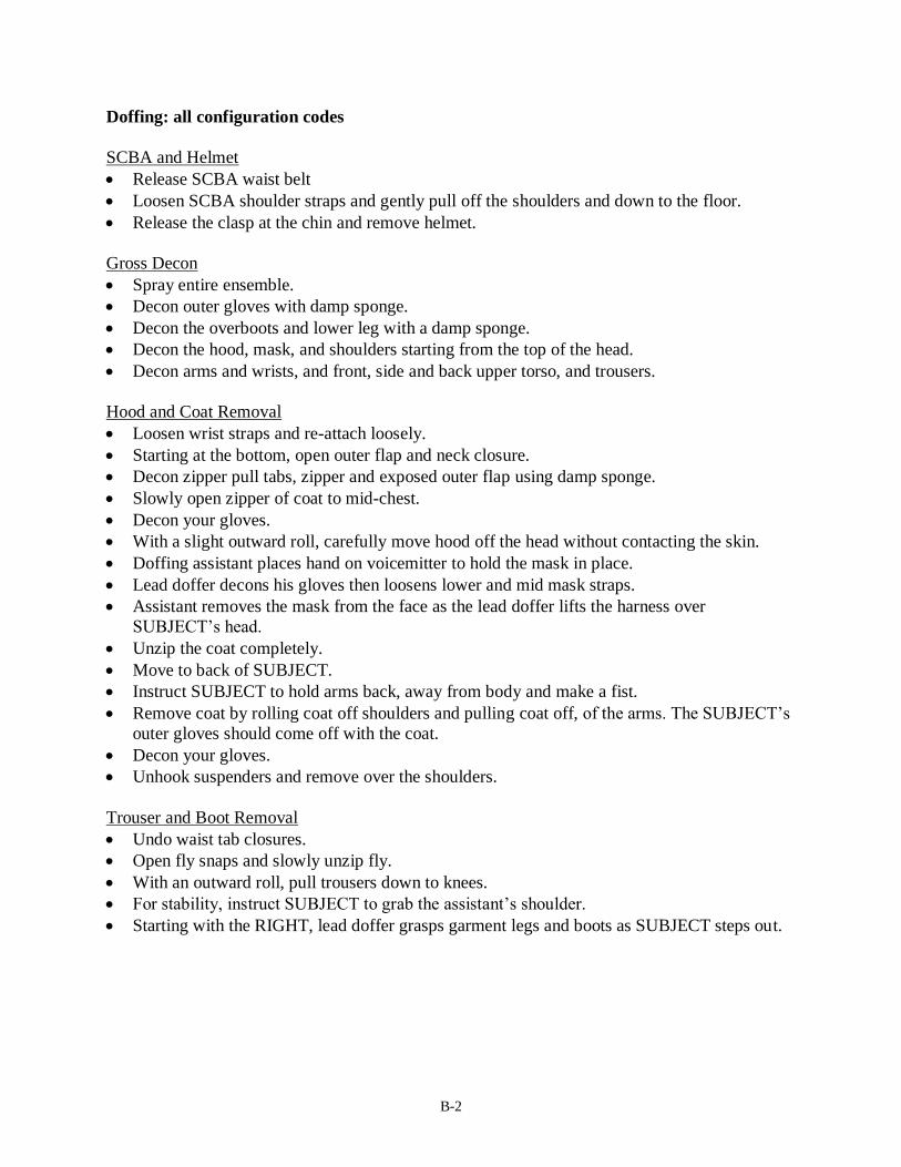
Doffing: all configuration codes
SCBA and Helmet
• Release SCBA waist belt
• Loosen SCBA shoulder straps and gently pull off the shoulders and down to the floor.
• Release the clasp at the chin and remove helmet.
Gross Decon
• Spray entire ensemble.
• Decon outer gloves with damp sponge.
• Decon the overboots and lower leg with a damp sponge.
• Decon the hood, mask, and shoulders starting from the top of the head.
• Decon arms and wrists, and front, side and back upper torso, and trousers.
Hood and Coat Removal
• Loosen wrist straps and re-attach loosely.
• Starting at the bottom, open outer flap and neck closure.
• Decon zipper pull tabs, zipper and exposed outer flap using damp sponge.
• Slowly open zipper of coat to mid-chest.
• Decon your gloves.
• With a slight outward roll, carefully move hood off the head without contacting the skin.
• Doffing assistant places hand on voicemitter to hold the mask in place.
• Lead doffer decons his gloves then loosens lower and mid mask straps.
• Assistant removes the mask from the face as the lead doffer lifts the harness over
SUBJECT’s head.
• Unzip the coat completely.
• Move to back of SUBJECT.
• Instruct SUBJECT to hold arms back, away from body and make a fist.
• Remove coat by rolling coat off shoulders and pulling coat off, of the arms. The SUBJECT’s
outer gloves should come off with the coat.
• Decon your gloves.
• Unhook suspenders and remove over the shoulders.
Trouser and Boot Removal
• Undo waist tab closures.
• Open fly snaps and slowly unzip fly.
• With an outward roll, pull trousers down to knees.
• For stability, instruct SUBJECT to grab the assistant’s shoulder.
• Starting with the RIGHT, lead doffer grasps garment legs and boots as SUBJECT steps out.
C-1
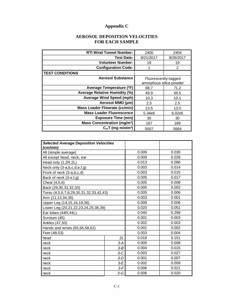
Appendix C
AEROSOL DEPOSITION VELOCITIES
FOR EACH SAMPLE
RTI Wind Tunnel Number: 2400 2404
Test Date: 9/21/2017 9/26/2017
Volunteer Number: 19 19
Configuration Code: 1 2
TEST CONDITIONS
Aerosol Substance Fluorescently-tagged amorphous silica powder
Average Temperature (ºF) 68.7 71.2
Average Relative Humidity (%) 49.9 49.5
Average Wind Speed (mph) 10.3 10.1
Aerosol MMD (µm) 2.5 2.5
Mass Loader Flowrate (cc/min) 13.5 13.5
Mass Loader Fluorescence 5.34e6 6.02e6
Exposure Time (min) 30 30
Mass Concentration (mg/m³) 167 189
CmT (mg min/m³) 5007 5684
Selected Average Deposition Velocities (cm/min)
All (simple average) 0.009 0.030
All except head, neck, ear 0.009 0.028
Head only (1,2R,2L) 0.013 0.086
Neck only (3-a,b,c,d,e,f,g) 0.003 0.014
Front of neck (3-a,b,c,d) 0.003 0.015
Back of neck (3-e,f,g) 0.005 0.017
Chest (4,5,6) 0.005 0.008
Back (29,30,31,32,33) 0.000 0.002
Torso (4,5,6,7,8,29,30,31,32,33,42,43) 0.005 0.006
Arm (11,13,34,35) 0.003 0.001
Upper Leg (14,15,16,18,36) 0.008 0.006
Lower Leg (20,21,22,23,24,25,38,39) 0.020 0.051
Ear lobes (44R,44L) 0.040 0.299
Scrotum (45) 0.001 0.003
Ankles (47,50) 0.002 0.003
Hands and wrists (55,56,58,62) 0.001 0.002
Feet (48,53) 0.003 0.004
head 2L 0.018 0.151
neck 3-A 0.005 0.008
neck 3-B 0.004 0.015
neck 3-C 0.003 0.027
neck 3-D 0.001 0.007
neck 3-E 0.002 0.009
neck 3-F 0.006 0.021
neck 3-G 0.006 0.020
C-2
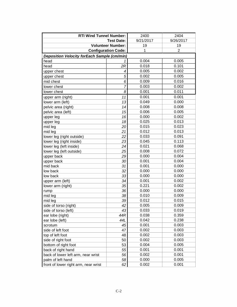
RTI Wind Tunnel Number: 2400 2404
Test Date: 9/21/2017 9/26/2017
Volunteer Number: 19 19
Configuration Code: 1 2
Deposition Velocity forEach Sample (cm/min)
head 1 0.004 0.005
head 2R 0.018 0.101
upper chest 4 0.005 0.002
upper chest 5 0.002 0.005
mid chest 6 0.009 0.016
lower chest 7 0.003 0.002
lower chest 8 0.001 0.011
upper arm (right) 11 0.001 0.001
lower arm (left) 13 0.049 0.000
pelvic area (right) 14 0.008 0.008
pelvic area (left) 15 0.006 0.005
upper leg 16 0.000 0.002
upper leg 18 0.025 0.013
mid leg 20 0.015 0.023
mid leg 21 0.012 0.013
lower leg (right outside) 22 0.033 0.091
lower leg (right inside) 23 0.045 0.113
lower leg (left inside) 24 0.021 0.068
lower leg (left outside) 25 0.008 0.072
upper back 29 0.000 0.004
upper back 30 0.001 0.004
mid back 31 0.001 0.000
low back 32 0.000 0.000
low back 33 0.000 0.000
upper arm (left) 34 0.001 0.002
lower arm (right) 35 0.221 0.002
rump 36 0.000 0.000
mid leg 38 0.010 0.009
mid leg 39 0.012 0.015
side of torso (right) 42 0.005 0.009
side of torso (left) 43 0.033 0.019
ear lobe (right) 44R 0.038 0.359
ear lobe (left) 44L 0.042 0.238
scrotum 45 0.001 0.003
side of left foot 47 0.002 0.003
top of left foot 48 0.002 0.003
side of right foot 50 0.002 0.003
bottom of right foot 53 0.004 0.005
back of right hand 55 0.001 0.001
back of lower left arm, near wrist 56 0.002 0.001
palm of left hand 58 0.000 0.005
front of lower right arm, near wrist 62 0.002 0.001
C-3
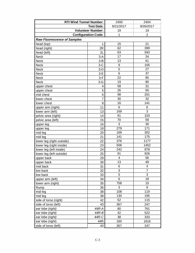
RTI Wind Tunnel Number: 2400 2404
Test Date: 9/21/2017 9/26/2017
Volunteer Number: 19 19
Configuration Code: 1 2
Raw Fluorescence of Samples
head (top) 1 15 21
head (right) 2R 62 399
head (left) 2L 63 593
Neck 3-A 17 34
Neck 3-B 13 61
Neck 3-C 9 105
Neck 3-D 5 27
Neck 3-E 6 37
Neck 3-F 22 85
Neck 3-G 19 80
upper chest 4 58 31
upper chest 5 26 65
mid chest 6 98 201
lower chest 7 30 32
lower chest 8 16 141
upper arm (right) 11 6 6
lower arm (left) 13 169 3
pelvic area (right) 14 91 103
pelvic area (left) 15 70 59
upper leg 16 3 30
upper leg 18 279 171
mid leg 20 169 302
mid leg 21 141 175
lower leg (right outside) 22 376 1177
lower leg (right inside) 23 508 1452
lower leg (left inside) 24 242 878
lower leg (left outside) 25 91 926
upper back 29 4 56
upper back 30 13 49
mid back 31 6 4
low back 32 3 7
low back 33 5 3
upper arm (left) 34 6 18
lower arm (right) 35 758 15
Rump 36 3 9
mid leg 38 108 119
mid leg 39 130 195
side of torso (right) 42 52 115
side of torso (left) 43 367 247
ear lobe (right) 44R-A 80 761
ear lobe (right) 44R-B 42 522
ear lobe (right) 44R-C 38 333
ear lobe (right) 44R 160 1616
side of torso (left) 43 367 247
C-4
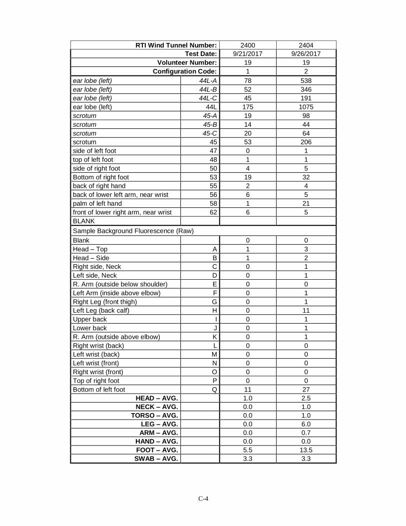
RTI Wind Tunnel Number: 2400 2404
Test Date: 9/21/2017 9/26/2017
Volunteer Number: 19 19
Configuration Code: 1 2
ear lobe (left) 44L-A 78 538
ear lobe (left) 44L-B 52 346
ear lobe (left) 44L-C 45 191
ear lobe (left) 44L 175 1075
scrotum 45-A 19 98
scrotum 45-B 14 44
scrotum 45-C 20 64
scrotum 45 53 206
side of left foot 47 0 1
top of left foot 48 1 1
side of right foot 50 4 5
Bottom of right foot 53 19 32
back of right hand 55 2 4
back of lower left arm, near wrist 56 6 5
palm of left hand 58 1 21
front of lower right arm, near wrist 62 6 5
BLANK
Sample Background Fluorescence (Raw)
Blank 0 0
Head – Top A 1 3
Head – Side B 1 2
Right side, Neck C 0 1
Left side, Neck D 0 1
R. Arm (outside below shoulder) E 0 0
Left Arm (inside above elbow) F 0 1
Right Leg (front thigh) G 0 1
Left Leg (back calf) H 0 11
Upper back I 0 1
Lower back J 0 1
R. Arm (outside above elbow) K 0 1
Right wrist (back) L 0 0
Left wrist (back) M 0 0
Left wrist (front) N 0 0
Right wrist (front) O 0 0
Top of right foot P 0 0
Bottom of left foot Q 11 27
HEAD – AVG. 1.0 2.5
NECK – AVG. 0.0 1.0
TORSO – AVG. 0.0 1.0
LEG – AVG. 0.0 6.0
ARM – AVG. 0.0 0.7
HAND – AVG. 0.0 0.0
FOOT – AVG. 5.5 13.5
SWAB – AVG. 3.3 3.3