Embed Size (px)
Citation preview

OWNER’S GUIDE
RXV ELiTE FREEDOM
657040 - D
Read and comply with all of the instructions and safety precautions in this manual and on all product labels.
Failure to follow the safety precautions could result in serious injury or death.
CALIFORNIA Proposition 65
Motor vehicles may contain fuels, oils and fluids, battery posts, terminals, and related accessories which con-tain lead and lead compounds and other chemicals identified by the State of California to potentially cause cancer, birth defects, and other reproductive harm. These chemicals are found in vehicles, vehicle parts and accessories, both new and replacements. During maintenance, these vehicles generate used oil, waste fluids, grease, fumes, and particulates, all identified by the State of California to potentially cause cancer and birth defects or other reproductive harm.
Posted in accordance with Proposition 65 and California Health and Safety Code Section 25249.5, et seq.
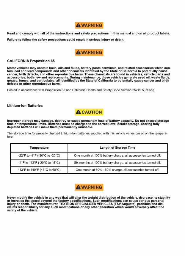
Lithium-Ion Batteries
Improper storage may damage, destroy or cause permanent loss of battery capacity. Do not exceed storage time or temperature limits. Batteries must be charged to the correct level before storage. Storing fully depleted batteries will make them permanently unusable.
The storage time for properly charged Lithium-Ion batteries supplied with this vehicle varies based on the tempera-ture.
Never modify the vehicle in any way that will alter the weight distribution of the vehicle, decrease its stability or increase the speed beyond the factory specifications. Such modifications can cause serious personal injury or death. The manufacturer, TEXTRON SPECIALIZED VEHICLES (TSV Augusta), prohibits and dis-claims responsibility for any such modifications or any other alteration which would adversely affect the safety of the vehicle.
Temperature Length of Storage Time
-22°F to -4°F (-30°C to -20°C) One month at 100% battery charge, all accessories turned off.
-4°F to 113°F (-20°C to 45°C) Six months at 100% battery charge, all accessories turned off.
113°F to 140°F (45°C to 60°C) One month at 30% - 50% charge, all accessories turned off.

i
OWNER’S GUIDE
48 V ELECTRIC RXV ELiTE
FREEDOM
Starting MODEL YEAR 2017production starting 1 January 2017
These are the original instructions as defined by 2006/42/EC.
CONTACT INFORMATION
Textron Specialized Vehicles, Inc.1451 Marvin Griffin RoadAugusta, Georgia, USA 30906-3852
North America:Technical Assistance and Warranty PHONE: 1-800-774-3946 FAX: 1-800-448-8124Service Parts PHONE: 1-888-438-3946 FAX: 1-800-752-6175International PHONE: 001-706-798-4311 FAX: 001-706-771-4609www.ezgo.com
ii
WELCOMEThank you for purchasing this vehicle. Before driving your new vehicle, read this owner’s guide to familiarize yourself with safe driving practices, operation, features and controls.This manual contains instructions for minor maintenance only. Information about major repairs can be found in the repair manual. Your dealer has thorough knowledge of your vehicle and wants your total satisfaction with your pur-chase. We recommend you return to your dealership for all of your service needs during, and after the warranty period.Repair or replacement parts can be purchased from your dealer or through the manufacturer’s parts and accessories department.
TSV maintains the right to change the design of the vehicle without responsibility to make the changes on units pur-chased before changes were made. The information in this manual can change without notice.All information in this owner’s guide is based on the latest product information at the time of publication. Due to con-stant improvements in the design and quality of production components, some discrepancies may be found between your vehicle and the information presented in this publication. The content in this publication is intended for reference use only. The manufacturer is not liable for omissions or inaccuracies. Any reprinting or reuse of the content in this publication, whether whole or in part, is expressly prohibited.
Printed in USA
TABLE OF CONTENTS
MANUFACTURER’S INTENDED USE ............................................................................................ 1WARRANTY AND REGISTRATION ................................................................................................ 1BATTERY PROLONGED STORAGE .............................................................................................. 1
Storage Preparation .................................................................................................................. 1
Setting State of Charge (SOC) .................................................................................................. 2
During Storage .......................................................................................................................... 2
Extreme Low Temperature Storage .......................................................................................... 2
Returning Vehicle to Service ..................................................................................................... 2
BATTERY DISPOSAL...................................................................................................................... 2VEHICLE SERIAL NUMBER LOCATION ........................................................................................ 3REPAIR AND PARTS MANUALS .................................................................................................... 3SAFETY ........................................................................................................................................... 5SAFETY LABELS............................................................................................................................. 5
Operation (P/N 608529 or 614044 for CE) ................................................................................ 5
Warning and Operation Label (P/N 608528 or 614043 for CE) ............................................... 6
Tow Bar Label (P/N 635906) ..................................................................................................... 6
Run/Storage - Tow Label (P/N 609987 or 610991 for CE) ........................................................ 6
Brake Release (P/N 609694 or 610990 for CE) ........................................................................ 7
Run/Storage-Tow Switch Operation (P/N 612594 or 608769 for CE) ....................................... 7
Battery Warning (P/N 655748 or 659260 for CE) ...................................................................... 7
MAXIMUM WEIGHT CAPACITY...................................................................................................... 7TIRE PRESSURE ............................................................................................................................ 8OPERATOR SAFETY ...................................................................................................................... 8
Unauthorized Operation ............................................................................................................ 9
Operating without Instruction ..................................................................................................... 9
Alcohol or Drugs ........................................................................................................................ 9
Before Operating ....................................................................................................................... 9
Operating With Passenger or Cargo ......................................................................................... 9
Driving in Reverse ..................................................................................................................... 9
Driving a Damaged Vehicle ....................................................................................................... 9
Driving at Maximum Speeds ..................................................................................................... 9
Driving on Different Surfaces .................................................................................................... 9
Driving on Public Roads ............................................................................................................ 9
iii
TABLE OF CONTENTS
iv
Turning .................................................................................................................................... 10
Driving Uphill ........................................................................................................................... 10
Driving Downhill ....................................................................................................................... 10
Stalling on a Hill ....................................................................................................................... 10
Tires ........................................................................................................................................ 10
Slippery Terrain ....................................................................................................................... 10
BATTERY CHARGING .................................................................................................................. 10VEHICLE LIFTING ......................................................................................................................... 11VEHICLE MODIFICATION............................................................................................................. 11MAINTENANCE SAFETY .............................................................................................................. 11KEY SWITCH /DIRECTION SELECTOR....................................................................................... 13HEADLIGHT SWITCH (IF EQUIPPED) ......................................................................................... 13STATE OF CHARGE METER (IF EQUIPPED).............................................................................. 13HORN (IF EQUIPPED)................................................................................................................... 13CUP HOLDER................................................................................................................................ 1312V OUTLET (IF EQUIPPED)........................................................................................................ 13USB PORT (IF EQUIPPED)........................................................................................................... 13STEERING WHEEL ....................................................................................................................... 13TURN SIGNAL (IF EQUIPPED) ..................................................................................................... 13ACCELERATOR PEDAL................................................................................................................ 13BRAKE PEDAL .............................................................................................................................. 14PARKING BRAKE .......................................................................................................................... 14SEAT BOTTOM.............................................................................................................................. 14GLOVE BOX / STORAGE COMPARTMENTS .............................................................................. 14CANOPY TOP AND WINDSHIELD................................................................................................ 14SAFETY ......................................................................................................................................... 15BEFORE INITIAL USE ................................................................................................................... 15DAILY INSPECTION ...................................................................................................................... 15ENVIRONMENTAL AWARENESS ................................................................................................ 15BATTERY CHARGER.................................................................................................................... 16PERFORMANCE FEATURES ....................................................................................................... 16
Speed Control ......................................................................................................................... 16
Pedal-Up Braking .................................................................................................................... 16
TABLE OF CONTENTS
High Pedal Disable Feature .................................................................................................... 16
STARTING AND STOPPING THE VEHICLE ................................................................................ 17Starting on a Hill ...................................................................................................................... 17
ACCELERATING ........................................................................................................................... 17BRAKING ....................................................................................................................................... 17
Coasting .................................................................................................................................. 17
DRIVING PROCEDURE ................................................................................................................ 17DRIVING WITH A PASSENGER ................................................................................................... 17SLIPPERY SURFACES ................................................................................................................. 18DRIVING UPHILL........................................................................................................................... 18TRAVERSING HILLSIDES............................................................................................................. 18DRIVING DOWNHILL .................................................................................................................... 18STALLING ON A HILL.................................................................................................................... 19DRIVING IN REVERSE.................................................................................................................. 19PARKING THE VEHICLE............................................................................................................... 19
Maximum Weight Capacity ...................................................................................................... 19
MAINTENANCE SAFETY .............................................................................................................. 21SCHEDULED MAINTENANCE ...................................................................................................... 21SCHEDULED MAINTENANCE CHART......................................................................................... 22RECOMMENDED LUBRICANTS AND FLUIDS ............................................................................ 23REPLACEMENT OF MAINTENANCE ITEMS ............................................................................... 23LIFTING THE VEHICLE ................................................................................................................. 24
Lifting Front ............................................................................................................................ 24
Lifting Rear .............................................................................................................................. 24
Lowering Vehicle ..................................................................................................................... 24
VEHICLE CLEANING AND CARE ................................................................................................. 25Washing the Vehicle ................................................................................................................ 25
Polishing the Vehicle ............................................................................................................... 25
TIRES............................................................................................................................................. 25Tire Pressure ........................................................................................................................... 26
Tire Repair ............................................................................................................................... 26
Tire Replacement .................................................................................................................... 26
WHEELS ........................................................................................................................................ 26Wheel Removal ....................................................................................................................... 26
v
TABLE OF CONTENTS
vi
Wheel Installation ................................................................................................................... 27
LIGHTS .......................................................................................................................................... 27Headlight Replacement ........................................................................................................... 27
Turn Signal (if equipped) ......................................................................................................... 27
Taillight .................................................................................................................................... 28
REAR AXLE ................................................................................................................................... 28LITHIUM-ION BATTERY PACK ..................................................................................................... 28BATTERY CHARGING AND MAINTENANCE............................................................................... 29BATTERY CHARGING .................................................................................................................. 29
AC Voltage .............................................................................................................................. 29
BATTERY PROLONGED STORAGE ............................................................................................ 30Storage Preparation ................................................................................................................ 30
BATTERY FAULT DIAGNOSIS ..................................................................................................... 30TRANSPORTING THE VEHICLE .................................................................................................. 31
Towing the Vehicle .................................................................................................................. 31
Manual Release of IntelliBrake™ ............................................................................................ 31
Hauling the Vehicle ................................................................................................................. 32
VEHICLE SPECIFICATIONS ......................................................................................................... 34BATTERY CHARGER USER’S GUIDE ....................................A1DECLARATION OF CONFORMITY .........................................B1
OPERATION
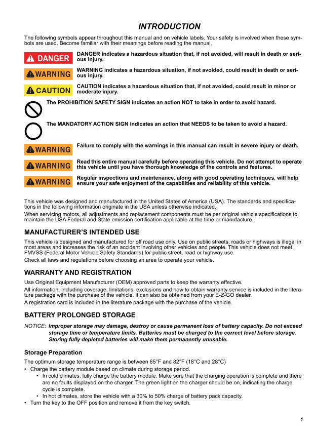
INTRODUCTIONThe following symbols appear throughout this manual and on vehicle labels. Your safety is involved when these sym-bols are used. Become familiar with their meanings before reading the manual.
DANGER indicates a hazardous situation that, if not avoided, will result in death or seri-ous injury.
WARNING indicates a hazardous situation, if not avoided, could result in death or seri-ous injury.
CAUTION indicates a hazardous situation that, if not avoided, could result in minor or moderate injury.
The PROHIBITION SAFETY SIGN indicates an action NOT to take in order to avoid hazard.
The MANDATORY ACTION SIGN indicates an action that NEEDS to be taken to avoid a hazard.
Failure to comply with the warnings in this manual can result in severe injury or death.
Read this entire manual carefully before operating this vehicle. Do not attempt to operate this vehicle until you have thorough knowledge of the controls and features.
Regular inspections and maintenance, along with good operating techniques, will help ensure your safe enjoyment of the capabilities and reliability of this vehicle.
This vehicle was designed and manufactured in the United States of America (USA). The standards and specifica-tions in the following information originate in the USA unless otherwise indicated.When servicing motors, all adjustments and replacement components must be per original vehicle specifications to maintain the USA Federal and State emission certification applicable at the time or manufacture.
MANUFACTURER’S INTENDED USEThis vehicle is designed and manufactured for off road use only. Use on public streets, roads or highways is illegal in most areas and increases the risk of an accident involving other vehicles and people. This vehicle does not meet FMVSS (Federal Motor Vehicle Safety Standards) for public street, road or highway use.Check all laws and regulations before choosing an area to operate your vehicle.
WARRANTY AND REGISTRATIONUse Original Equipment Manufacturer (OEM) approved parts to keep the warranty effective.All information, including coverage, limitations, exclusions and how to obtain warranty service is included in the litera-ture package with the purchase of the vehicle. It can also be obtained from your E-Z-GO dealer.A registration card is included in the literature package with the purchase of the vehicle.
BATTERY PROLONGED STORAGENOTICE: Improper storage may damage, destroy or cause permanent loss of battery capacity. Do not exceed
storage time or temperature limits. Batteries must be charged to the correct level before storage. Storing fully depleted batteries will make them permanently unusable.
Storage PreparationThe optimum storage temperature range is between 65°F and 82°F (18°C and 28°C)• Charge the battery module based on climate during storage period.
• In cold climates, fully charge the battery module. Make sure that the charging operation is complete and there are no faults displayed on the charger. The green light on the charger should be on, indicating the charge cycle is complete.
• In hot climates, store the vehicle with a 30% to 50% charge of battery pack capacity.• Turn the key to the OFF position and remove it from the key switch.
1
OPERATION
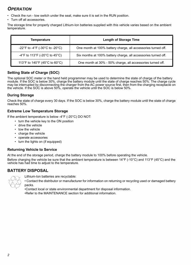
• Check the run - tow switch under the seat, make sure it is set in the RUN position.• Turn off all accessories.The storage time for properly charged Lithium-Ion batteries supplied with this vehicle varies based on the ambient temperature.Setting State of Charge (SOC)The optional SOC meter or the hand held programmer may be used to determine the state of charge of the battery module. If the SOC is below 30%, charge the battery module until the state of charge reaches 50%. The charge cycle may be interrupted by disconnecting the charger from the AC power source first, then from the charging receptacle on the vehicle. If the SOC is above 50%, operate the vehicle until the SOC is below 50%.
During StorageCheck the state of charge every 30 days. If the SOC is below 30%, charge the battery module until the state of charge reaches 50%.
Extreme Low Temperature StorageIf the ambient temperature is below -4°F (-20°C) DO NOT:
• turn the vehicle key to the ON position• drive the vehicle• tow the vehicle• charge the vehicle• operate accessories• turn the lights on (if equipped)
Returning Vehicle to ServiceAt the end of the storage period, charge the battery module to 100% before operating the vehicle. Before charging the vehicle be sure that the ambient temperature is between 14°F (-10°C) and 113°F (45°C) and the vehicle has had time to adjust to the temperature.
BATTERY DISPOSALLithium-Ion batteries are recyclable:• Contact the distributor or manufacturer for information on returning or recycling used or damaged battery packs. •Contact local or state environmental department for disposal information. •Refer to the MAINTENANCE section for additional information.
Temperature Length of Storage Time
-22°F to -4°F (-30°C to -20°C) One month at 100% battery charge, all accessories turned off.
-4°F to 113°F (-20°C to 45°C) Six months at 100% battery charge, all accessories turned off.
113°F to 140°F (45°C to 60°C) One month at 30% - 50% charge, all accessories turned off.
2
OPERATION
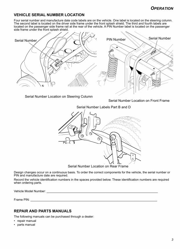
VEHICLE SERIAL NUMBER LOCATIONFour serial number and manufacture date code labels are on the vehicle. One label is located on the steering column. The second label is located on the driver side frame under the front splash shield. The third and fourth labels are located on the passenger side frame rail at the rear of the vehicle. A PIN Number label is located on the passenger side frame under the front splash shield.Design changes occur on a continuous basis. To order the correct components for the vehicle, the serial number or PIN and manufacture date are required.Record the vehicle identification numbers in the spaces provided below. These identification numbers are required when ordering parts.
Vehicle Model Number: _________________________________________________________________
Frame PIN: __________________________________________________________________________
REPAIR AND PARTS MANUALSThe following manuals can be purchased through a dealer:• repair manual• parts manual
Serial Number Location on Front Frame
Serial Number
Serial Number Location on Rear Frame
Serial Number Labels Part B and D
Serial Number
Serial Number Location on Steering Column
PIN Number
3

OPERATION
4
SAFETY
SAFETYSAFETYFor questions about your vehicle or the material in this manual, see the contact information on page i or the back of this publication.
Certain replacement parts can be used independently and/or in combination with other accessories to modify a TSV (Augusta) manufactured vehicle to permit the vehicle to operate at or in excess of 20 mph. When a TSV-manufactured vehicle is modified in any way by the Distributor, Dealer or customer to operate at or in excess of 20 mph on public streets or roads, UNDER FEDERAL LAW the modified product will be a Low Speed Vehicle (LSV) subject to the stric-tures and requirements of Federal Motor Vehicle Safety Standard 571.500. In these instances, pursuant to Federal law the Distributor or Dealer MUST equip the product with headlights, rear lights, turn signals, seat belts, top, horn and all other modifications for LSV’s mandated in FMVSS 571.500, and affix a Vehicle Identification Number to the product in accordance with the requirements of FMVSS 571.565. Pursuant to FMVSS 571.500, and in accordance with the State laws applicable in the places of sale and use of the product, the Distributor, Dealer or customer modifying the vehicle also will be the Final Vehicle Manufacturer for the LSV, and required to title or register the vehicle as man-dated by State law.Information on FMVSS 571.500 is found at Title 49 of the Code of Federal Regulations, section 571.500. For informa-tion on-line, go to www.ecfr.gov.TSV will NOT approve Distributor, Dealer or customer changes that change a TSV product into a Low Speed Vehicle (LSV).This vehicle meets the current applicable standard for safety and performance requirements.
SAFETY LABELSSafety and warning labels are on the vehicle for your protection. Read and comply with the instructions on the labels carefully. If any label shown in this manual is different from the label on your vehicle, always follow the instructions on the vehicle label.If a label comes off or becomes illegible, contact your TSV dealer for a replacement. The part number is provided in this manual, printed on the label, or can be obtained from your dealer.
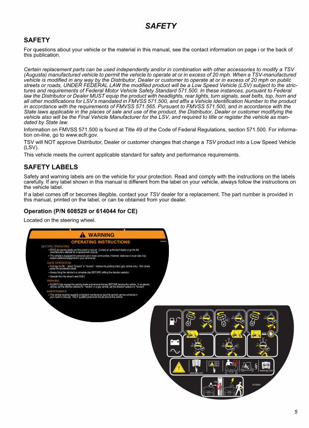
Operation (P/N 608529 or 614044 for CE)Located on the steering wheel.
BEFORE OPERATING READ all warning labels and the owner’s manual. Contact an authorized dealer or go the the
manufacturer’s website for a replacement manual.
SAFE OPERATION Turn key to ON - select “forward” or “reverse” - release the parking brake (gas vehicle only) - then slowly
press the accelerator pedal.
PARKING
MAINTENANCE
ALWAYS fully engage the parking brake and remove the key BEFORE leaving the vehicle. In an electric vehicle, set the direction selector to “neutral”; in a gas vehicle, set the direction selector to “forward”.
This vehicle requires regularly scheduled maintenance (see the periodic service schedule in your owner’s manual). ONLY qualified personnel should service this vehicle.
OPERATING INSTRUCTIONS 608529
This vehicle is equipped for personal use in most communities. However, state law or local rules may require additional equipment in your community.
Operate from the driver’s seat ONLY.Always bring the vehicle to a complete stop BEFORE shifting the direction selector.
614044
NON FR
FFOO
NOFR
FFOO
N
NO
FFO
I
ORF
RF
NO
FFO
I
O
NON FR
FFOO
RF
NO
FFO
I
O
P
www.ezgo.comwww.ezgo.com
cm
150
5
SAFETY
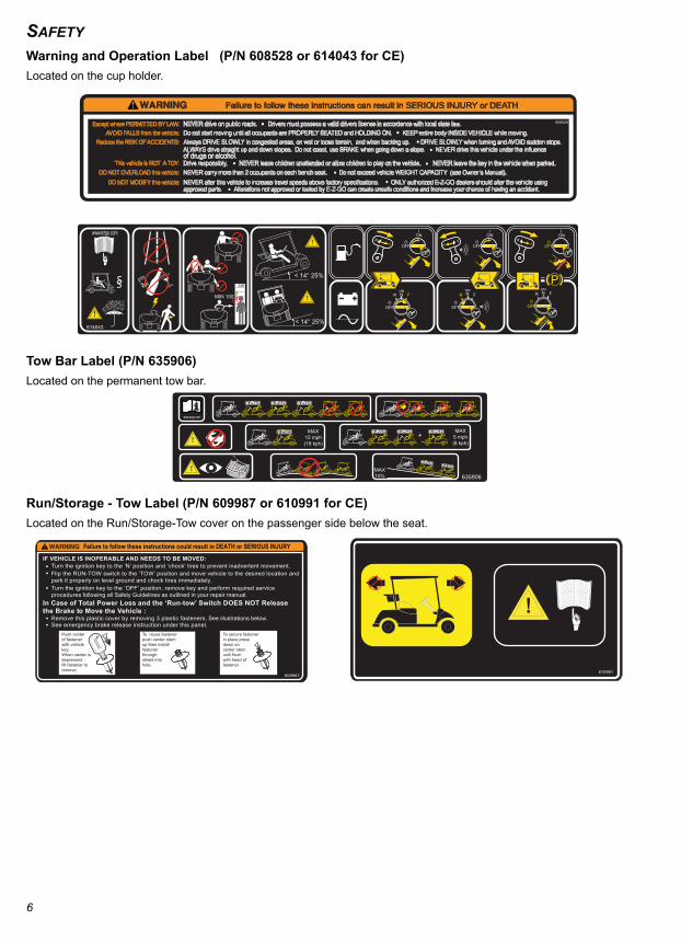
Warning and Operation Label (P/N 608528 or 614043 for CE)Located on the cup holder.Tow Bar Label (P/N 635906)Located on the permanent tow bar.
Run/Storage - Tow Label (P/N 609987 or 610991 for CE)Located on the Run/Storage-Tow cover on the passenger side below the seat.
608528
Failure to follow these instructions can result in SERIOUS INJURY or DEATH
Except where PERMITTED BY LAW:
NEVER drive on public roads. Drivers must possess a valid drivers license in accordance with local state law.AVOID FALLS from the vehicle:
Do not start moving until all occupants are PROPERLY SEATED and HOLDING ON. KEEP entire body INSIDE VEHICLE while moving.
Reduce the RISK OF ACCIDENTS:
Always DRIVE SLOWLY in congested areas, on wet or loose terrain, and when backing up. DRIVE SLOWLY when turning and AVOID sudden stops. ALWAYS drive straight up and down slopes. Do not coast, use BRAKE when going down a slope. NEVER drive this vehicle under the influence of drugs or alcohol.
This vehicle is NOT A TOY:
Drive responsibly. NEVER leave children unattended or allow children to play on the vehicle. NEVER leave the key in the vehicle when parked.DO NOT OVERLOAD this vehicle:
NEVER carry more than 2 occupants on each bench seat. Do not exceed vehicle WEIGHT CAPACITY (see Owner’s Manual).
DO NOT MODIFY this vehicle:
NEVER alter this vehicle to increase travel speeds above factory specifications. ONLY authorized E-Z-GO dealers should alter the vehicle using approved parts. Alterations not approved or tested by E-Z-GO can create unsafe conditions and increase your chance of having an accident.
< 14° 25%
< 14° 25%
cm
MIN 150ONN FR
OFFO
RF
ON
OFF
I
OR
FON
OFF
I
O
ONN FR
OFFO
614043
FR
OFFO
ONN
ON
OFF
I
ORF
635906
MAX5 mph(8 kph)
+MAX
12 mph(19 kph)
MAX10%
To secure fastenerin place pressdown on center stem until flush with head offastener.
To reuse fastenerpush center stemup then installfastener throughshield intohole.
Push center of fastener with vehiclekey. When center isdepressedlift fastener to remove.
See emergency brake release instruction under this panel.Remove this plastic cover by removing 3 plastic fasteners. See illustrations below.
609987
Turn the ignition key to the ‘N’ position and ‘chock’ tires to prevent inadvertent movement.
Turn the ignition key to the ‘OFF’ position, remove key and perform required service procedures following all Safety Guidelines as outlined in your repair manual.
Flip the RUN-TOW switch to the ‘TOW’ position and move vehicle to the desired location and park it properly on level ground and chock tires immediately.
In Case of Total Power Loss and the ‘Run-tow’ Switch DOES NOT Release the Brake to Move the Vehicle :
IF VEHICLE IS INOPERABLE AND NEEDS TO BE MOVED:
Failure to follow these instructions could result in DEATH or SERIOUS INJURY
610991
6
SAFETY
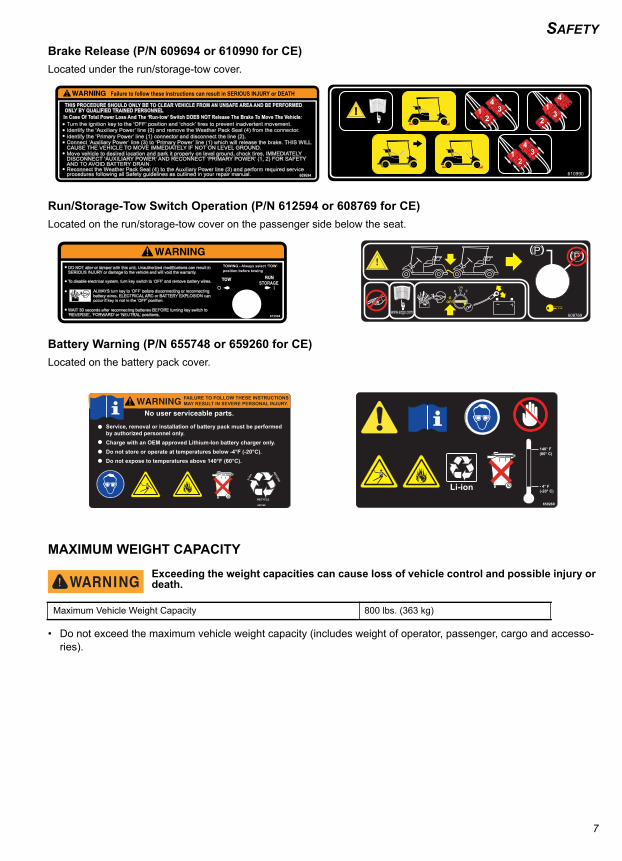
Brake Release (P/N 609694 or 610990 for CE)Located under the run/storage-tow cover.Run/Storage-Tow Switch Operation (P/N 612594 or 608769 for CE)Located on the run/storage-tow cover on the passenger side below the seat.
Battery Warning (P/N 655748 or 659260 for CE)Located on the battery pack cover.
MAXIMUM WEIGHT CAPACITY
Exceeding the weight capacities can cause loss of vehicle control and possible injury or death.
• Do not exceed the maximum vehicle weight capacity (includes weight of operator, passenger, cargo and accesso-ries).
Maximum Vehicle Weight Capacity 800 lbs. (363 kg)
609694
Failure to follow these instructions can result in SERIOUS INJURY or DEATH
THIS PROCEDURE SHOULD ONLY BE TO CLEAR VEHICLE FROM AN UNSAFE AREA AND BE PERFORMEDONLY BY QUALIFIED TRAINED PERSONNEL In Case Of Total Power Loss And The ‘Run-tow’ Switch DOES NOT Release The Brake To Move The Vehicle:
Turn the ignition key to the ‘OFF’ position and ‘chock’ tires to prevent inadvertent movement.
Connect ‘Auxiliary Power’ line (3) to ‘Primary Power’ line (1) which will release the brake. THIS WILLCAUSE THE VEHICLE TO MOVE IMMEDIATELY IF NOT ON LEVEL GROUND.Move vehicle to desired location and park it properly on level ground, chock tires, IMMEDIATELYDISCONNECT ‘AUXILIARY POWER’ AND RECONNECT ‘PRIMARY POWER’ (1, 2) FOR SAFETYAND TO AVOID BATTERY DRAIN.Reconnect the Weather Pack Seal (4) to the Auxiliary Power line (3) and perform required serviceprocedures following all Safety guidelines as outlined in your repair manual.
Identify the ‘Auxiliary Power’ line (3) and remove the Weather Pack Seal (4) from the connector.Identify the ‘Primary Power’ line (1) connector and disconnect the line (2).
12
34 1
23
4
12
34
610990
DO NOT alter or tamper with this unit. Unauthorized modifications can result in SERIOUS INJURY or damage to the vehicle and will void the warranty.
WAIT 30 seconds after reconnecting batteries BEFORE turning key switch to ‘REVERSE’, ‘FORWARD’ or ‘NEUTRAL’ positions.
TOWING - Always select ‘TOW’position before towing
612594
To disable electrical system, turn key switch to ‘OFF’ and remove battery wires.
ALWAYS turn key to ‘OFF’ before disconnecting or reconnecting battery wires. ELECTRICAL ARC or BATTERY EXPLOSION can occur if key is not in the ‘OFF’ position.
STORAGE
608769
FR
OFFO
ONN
659260
Li-ion
140° F(60° C)
- 4° F(-20° C)
FAILURE TO FOLLOW THESE INSTRUCTIONSMAY RESULT IN SEVERE PERSONAL INJURY.
RECYCLE
RETURNLi-Io
n
Service, removal or installation of battery pack must be performedby authorized personnel only.Charge with an OEM approved Lithium-Ion battery charger only.Do not store or operate at temperatures below -4°F (-20°C).Do not expose to temperatures above 140°F (60°C).
No user serviceable parts.
655748
7
SAFETY
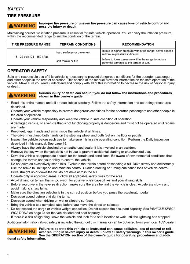
TIRE PRESSUREImproper tire pressure or uneven tire pressure can cause loss of vehicle control and possible injury or death.
Maintaining correct tire inflation pressure is essential for safe vehicle operation. You can vary the inflation pressure, within the recommended range to suit the condition of the terrain.
OPERATOR SAFETYSafe and responsible use of this vehicle is necessary to prevent dangerous conditions for the operator, passengers and other people in the area of operation. This section of the manual provides information on the safe operation of the vehicle. Make sure you read, understand and comply with all of this information to decrease the risk of personal injury or death.
Serious injury or death can occur if you do not follow the instructions and procedures shown in this owner’s guide.
• Read this entire manual and all product labels carefully. Follow the safety information and operating procedures described.
• Operate your vehicle responsibly to prevent dangerous conditions for the operator, passengers and other people in the area of operation
• Operate your vehicle responsibly and keep the vehicle in safe condition of operation.• A damaged vehicle, or a vehicle that is not functioning properly is dangerous and must not be operated until repairs
are made.• Keep feet, legs, hands and arms inside the vehicle at all times.• The driver must keep both hands on the steering wheel and both feet on the floor or pedals.• Inspect the vehicle before each use to make sure it is in safe operating condition. Perform the Daily inspection
described in this manual. See page 15.• Always have the vehicle checked by an authorized dealer if it is involved in an accident.• Remove the key when the vehicle is not in use to prevent accidental starting or unauthorized use.• Drive the vehicle at appropriate speeds for the terrain and conditions. Be aware of environmental conditions that
change the terrain and your ability to control the vehicle.• Do not drive on excessively steep hills. Evaluate the terrain before descending a hill. Drive slowly and deliberately.
Use the brake to limit speed and maintain control. Sudden braking or turning can cause loss of vehicle control. Drive straight up or down the hill; do not drive across the hill.
• Operate only in approved areas. Follow all applicable safety rules for the area.• Avoid driving on terrain that is too rough for your vehicle’s capabilities and your driving skills.• Before you drive in the reverse direction, make sure the area behind the vehicle is clear. Accelerate slowly and
avoid making sharp turns.• Make sure the direction selector is in the correct position before you press the accelerator pedal.• Decrease speed before and during turns. • Decrease speed when driving on wet or slippery surfaces.• Bring the vehicle to a complete stop before you move the direction selector.• Do not exceed the cargo or vehicle weight capacities. Do not exceed the occupant capacity. See VEHICLE SPECI-
FICATIONS on page 34 for the vehicle load and seat capacity.• If there is a risk of lightning, leave the vehicle and look for a safe location to wait until the lightning has stopped.Additional information about safety is included throughout this manual or can be obtained from your local TSV dealer.
Failure to operate this vehicle as instructed can cause collision, loss of control or roll-over resulting in severe injury or death. Follow all safety warnings in this owner’s guide. See the OPERATION section of the owner’s guide for operating procedures and addi-
tional safety information.
TIRE PRESSURE RANGE TERRAIN CONDITIONS RECOMMENDATION
18 - 22 psi (124 - 152 kPa)hard surfaces or pavement Inflate to higher pressure within the range; never exceed
maximum pressure indicated.
soft terrain or turf Inflate to lower pressure within the range to reduce potential damage to the terrain or turf.
8
SAFETY
Unauthorized OperationAny person who does not have a valid driver’s license is not permitted to operate the vehicle.Any person who is be below the height of 59 in. (150 cm) is not permitted to operate the vehicle.Leaving the keys in the ignition allows unauthorized operation of the vehicle by an unlicensed driver or someone who does not meet the height requirement. Always remove the ignition key when the vehicle is not in operation.Operating without InstructionOperation of this vehicle without proper instruction increases the risk of an accident. The operator must understand how to operate the vehicle correctly in different situations and on different types of terrain.All operators must read, understand and comply with the all warning and instruction labels before operating the vehicle.
Alcohol or DrugsOperation of the vehicle during or after consuming alcohol or drugs can adversely affect operator judg-ment, reaction time, balance and perception.Never drink alcohol or use drugs or medications before or during operation of the vehicle.
Before OperatingPerform the DAILY INSPECTION on page 15 before each use to make sure the vehicle is in safe operating condition. Failure to inspect and confirm that the vehicle is safe to operate increases the risk of an accident.Follow all inspection and maintenance procedures and schedules described in this owner’s guide. See SCHEDULED MAINTENANCE on page 21.
Operating With Passenger or CargoThe weight of cargo and occupants affects vehicle operation. Carefully calculate how the vehicle is loaded and how to safely operate it.Do not exceed weight capacities specified for your vehicle. Capacities are listed in MAXIMUM WEIGHT CAPACITY on page 7 of this manual, and also on the label affixed to the truck bed. As passenger weight increases, cargo weight needs to be adjusted to ensure the maximum vehicle weight capacity is not exceeded.
Driving in ReverseMake sure the area behind the vehicle is clear before operating in reverse. After making sure it is clear and safe to operate in reverse, accelerate slowly. Avoid making sharp turns in reverse. Refer to DRIVING IN REVERSE on page 19 for operational information.
Driving a Damaged VehicleDriving a damaged vehicle is not safe.If your vehicle has been involved in any type of accident, have it inspected by a qualified service dealer to verify that it is safe for operation.
Driving at Maximum SpeedsMaximum speed operation increases risk of loss of control. Always drive at a speed that is appropriate for the terrain, visibility, operating conditions and your skill and experience level. Use the brake to control speed and maintain control of the vehicle.
Driving on Different SurfacesDriving the vehicle on different surface types can affect handling characteristics of the vehicle. When driving on a dirt road, loose surface or wet grass, the distance required to stop the vehicles will increase.
Driving on Public RoadsDriving this vehicle on public streets, roads or highways could result in a collision with another vehicle. Never drive this vehicle on any public street, road or highway, including dirt and gravel roads, unless they are designated for off road use. Most areas prohibit the operation of this vehicle on public streets, roads or highways, and can result in traffic vio-lations and fines.
9
SAFETY
TurningImproper or careless turning can cause loss of traction, loss of control, accident or rollover. Do not turn quickly or at sharp angles. Do not turn at high speeds. Practice turning at slow speeds before attempting to turn at faster speeds.Driving UphillDo not climb hills that are too steep for the vehicle or your driving abilities. Loss of vehicle control or rollover can result from climbing hills incorrectly. Refer to Driving Uphill on page 18 for operational information.
Driving DownhillInspect the terrain before descending a hill. Avoid driving across hills. Use the brake to limit speed and maintain con-trol. Loss of vehicle control or rollover can result from driving downhill incorrectly. Refer to Driving Downhill on page 18 for operational information.
Stalling on a HillA rollover can result from stalling or rolling backward while climbing a hill. Drive uphill at a constant speed. See proce-dure on page 19 for maintaining control of your vehicle if it stalls on a hill.
TiresOperating the vehicle with incorrect tires or with incorrect or uneven tire pressure can cause loss of control or an acci-dent. Always use the size and type tires specified for the vehicle. See VEHICLE SPECIFICATIONS on page 34. Always maintain correct tire pressures as specified in Tire Pressure on page 8.
Slippery TerrainDriving on rough, wet or loose terrain increases the risk of loss of traction or control, accident or rollover. Drive slowly and use correct turning procedures when operating on slippery surfaces.Tires that have lost traction, and then regain traction suddenly, can cause loss of vehicle control or rollover.Refer to Slippery Surfaces on page 18 for operational information.
BATTERY CHARGINGCharging should be performed when ambient temperatures are between 40°F and 110°F (4°C and 42°C). The battery pack may be charged or topped off after every use.The battery management system (BMS) and charger cooperate to make sure that charging occurs at the proper rate for the battery temperature. When the battery charger is connected to the vehicle, it will determine the charge rate based on the battery temperature. The charger will operate at the rates shown in the table below.
The BMS will adjust the charge rate based on the temperature of the batteries. Use only the OEM approved Lithium-Ion battery charger for your vehicle. See charger operating instructions in Appen-dix A.• Turn the key to the OFF position and remove it from the vehicle.• Inspect the charger cord for cracks, frayed wires or loose connections. If damaged, replace it.• Inspect the vehicle charger receptacle and charger plug for dirt, debris or damage. Clean if necessary and replace
immediately if damage is found.• Connect the charger to a wall receptacle. Do not use a multi-plug adapter or power strip. Do not connect anything
else to the same receptacle.• Connect the charger to the vehicle receptacle.• When the battery pack is finished charging, disconnect the charger cord from the vehicle. If disconnecting before
the charge cycle is complete, it is recommended that the charger be disconnected from the wall receptacle first, then unplug the charger from the vehicle receptacle.
Charge Rate Temperature
NO charging below 14° F (-10°C) or above 140°F (60°C)
Pre-charge (charge at reduced rate, 6 amps) between 14°F (-10°C) and 41°F (5°C)between 104°F (40°C) and 140°F (60°C)
Full charging between 37.4°F (3°C) and 107.6°F (42° C)
10
SAFETY
VEHICLE LIFTINGThe vehicle must be on a firm and level surface for lifting. Remain constantly aware that the vehicle is not stable during the lifting process. Do not get under a vehicle until you verify that it is stable on the jack stands. Never get under a vehicle while it is on a jack only. Put wheel chocks in front and behind the wheels that are not being lifted. Do not allow anyone to remain or get on the vehicle at any time during the lifting process. Read and comply with all warnings and follow the lifting procedures described on page 24.VEHICLE MODIFICATIONDo not install any accessory not approved by TSV. Do not modify the vehicle to increase speed or power. Any modifi-cations or installation of accessories not approved by TSV can create a safety hazard and increase the risk of injury.The warranty will be terminated if the vehicle is modified to increase vehicle speed or power.The warranty may be terminated if original (or equivalent) replacement parts are not installed on the vehicle.The addition of some accessories can change the handling characteristics of the vehicle. Use only TSV approved accessories, and familiarize yourself with their function and effect on the vehicle.
MAINTENANCE SAFETYRoutine and scheduled maintenance of this vehicle is necessary to keep your vehicle in safe and reliable condition. This section of the manual provides safety information for performing maintenance on your vehicle. Make sure you read, understand and comply with all of this information to decrease the risk of personal injury or death.
Serious injury or death can occur if you do not follow the instructions and procedures shown in this owner’s guide.
• Read this entire manual and all product labels carefully. Follow the procedures and comply with the safety informa-tion in this manual while performing vehicle service or maintenance.
• Use the tools shown in the tool list and wear the specified safety equipment when performing vehicle service or maintenance.
• Remove all jewelry before you service the vehicle.• Do not allow loose clothing or hair to contact the moving parts.• Do not touch hot objects.• The drive wheels must be lifted and supported on jack stands before you perform any service to the power-train
while the motor is in operation.• Use wheel chocks and support the vehicle on jack stands. NEVER get under a vehicle that is supported by a jack.
Lift the vehicle following instructions. See LIFTING THE VEHICLE on page 24.•When you service the vehicle, always wear eye protection.•Wear a face shield when working around the battery pack.• Be careful when working around batteries, using solvents or compressed air.•Use insulated tools within the battery area to prevent sparks or battery explosion.•To prevent the risk of battery explosion, keep all flammable materials, open flames or sparks away from the battery.
• Maintain constant awareness that some components are heavy, spring loaded, corrosive, explosive, can cause high amperage or get extremely hot.
• After you make repairs or do maintenance, test the vehicle in a safe area that is free from vehicle and pedestrian traffic.
11

SAFETY
12
FEATURES AND CONTROLS
FEATURES AND CONTROLSNOTICE: 12V accessories must be connected to the DC to DC converter.
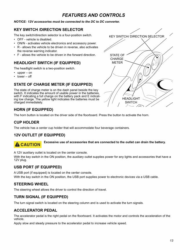
KEY SWITCH /DIRECTION SELECTORThe key switch/direction selector is a four-position switch. • OFF - vehicle is disabled.• ON/N - activates vehicle electronics and accessory power.• R - allows the vehicle to be driven in reverse, also activates
the reverse warning indicator.• F - allows the vehicle to be driven in the forward direction.
HEADLIGHT SWITCH (IF EQUIPPED)The headlight switch is a two-position switch.• upper – on• lower – off
STATE OF CHARGE METER (IF EQUIPPED)The state of charge meter is on the dash panel beside the key switch. It indicates the amount of usable power in the batteries, with F indicating a full charge on the battery pack and E indicat-ing low charge. The yellow light indicates the batteries must be charged immediately.
HORN (IF EQUIPPED)The horn button is located on the driver side of the floorboard. Press the button to activate the horn.
CUP HOLDERThe vehicle has a center cup holder that will accommodate four beverage containers.
12V OUTLET (IF EQUIPPED)
Excessive use of accessories that are connected to the outlet can drain the battery.
A 12V auxiliary outlet is located on the center console.With the key switch in the ON position, the auxiliary outlet supplies power for any lights and accessories that have a 12V plug.
USB PORT (IF EQUIPPED)A USB port (if equipped) is located on the center console.With the key switch in the ON position, the USB port supplies power to electronic devices via a USB cable.
STEERING WHEELThe steering wheel allows the driver to control the direction of travel.
TURN SIGNAL (IF EQUIPPED)The turn signal switch is located on the steering column and is used to activate the turn signals.
ACCELERATOR PEDALThe accelerator pedal is the right pedal on the floorboard. It activates the motor and controls the acceleration of the vehicle.Apply slow and steady pressure to the accelerator pedal to increase vehicle speed.
KEY SWITCH/ DIRECTION SELECTOR
STATE OFCHARGE METER
HEADLIGHTSWITCH
13
FEATURES AND CONTROLS
BRAKE PEDALThe brake pedal is the left pedal on the floorboard.Press the brake pedal to slow the speed or bring the vehicle to a complete stop.PARKING BRAKE This vehicle is equipped with an IntelliBrake™, an automatic parking brake that is activated when the vehicle is stopped. The brake is released when the vehicle is in the F (forward) or R (reverse) position and the accelerator pedal is pressed.
SEAT BOTTOMThe bench seat is designed for two occupants. Lift up on either hip restraint to pivot the seat bottom forward and access the components underneath. Pivot and lift up on the seat to completely remove it from the vehicle.
GLOVE BOX / STORAGE COMPARTMENTSThe glove box provides storage space for small items. Glove boxes may be equipped with optional doors.
CANOPY TOP AND WINDSHIELD
The canopy top does not provide protection from rollover or falling objects.
The windshield does not provide protection from tree branches or moving objects.
NOTICE: To prevent damage to the vehicle, do not hold on to the canopy top struts.
The canopy top and windshield provide some protection from the elements, but do not keep the operator and passen-ger dry in heavy rain.This vehicle is not equipped with seat belts, and the canopy top is not designed to provide rollover protection. In addi-tion, the canopy top does not protect against falling objects, nor does the windshield protect against flying objects and tree limbs.
14
OPERATION
OPERATIONSAFETY
Failure to operate the vehicle correctly can result in a collision, loss of control, accident or rollover, and cause serious injury or death. Follow all operation procedures in this section of the manual. Read and comply with all safety warnings in the safety section of this owner’s guide. This is a light-duty vehicle, NOT an All Terrain Vehicle (ATV).
BEFORE INITIAL USETo prepare your new vehicle for operation, complete the following:• Remove the protective plastic from the seats.• Check for possible leaks that may have developed during shipment of the vehicle.
Never charge a vehicle near flammable materials, open flame or sparks. Never charge a vehicle near gas water heaters and furnaces.
• Charge the batteries fully. See Battery Charging in the MAINTENANCE section of this manual.• Perform the following daily inspection.
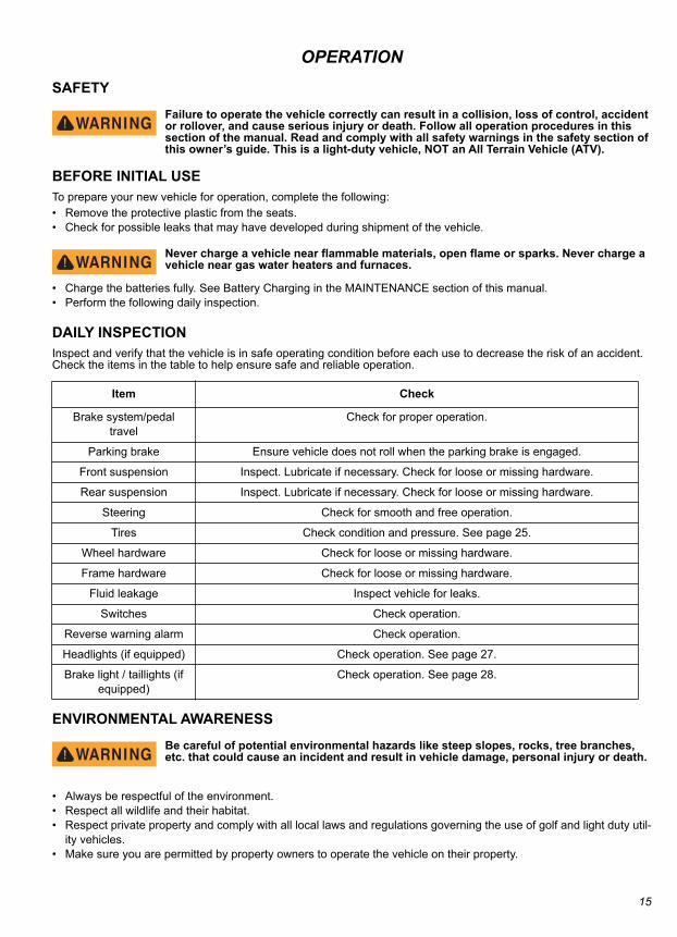
DAILY INSPECTIONInspect and verify that the vehicle is in safe operating condition before each use to decrease the risk of an accident. Check the items in the table to help ensure safe and reliable operation.
ENVIRONMENTAL AWARENESS
Be careful of potential environmental hazards like steep slopes, rocks, tree branches, etc. that could cause an incident and result in vehicle damage, personal injury or death.
• Always be respectful of the environment. • Respect all wildlife and their habitat.• Respect private property and comply with all local laws and regulations governing the use of golf and light duty util-
ity vehicles.• Make sure you are permitted by property owners to operate the vehicle on their property.
Item Check
Brake system/pedal travel
Check for proper operation.
Parking brake Ensure vehicle does not roll when the parking brake is engaged.
Front suspension Inspect. Lubricate if necessary. Check for loose or missing hardware.
Rear suspension Inspect. Lubricate if necessary. Check for loose or missing hardware.
Steering Check for smooth and free operation.
Tires Check condition and pressure. See page 25.
Wheel hardware Check for loose or missing hardware.
Frame hardware Check for loose or missing hardware.
Fluid leakage Inspect vehicle for leaks.
Switches Check operation.
Reverse warning alarm Check operation.
Headlights (if equipped) Check operation. See page 27.
Brake light / taillights (if equipped)
Check operation. See page 28.
15
OPERATION
BATTERY CHARGERThe charger should be operated in accordance with the charger manufacturer’s instructions. Always place the charger outside the vehicle before and during the charging cycle. Never charge batteries in a hazardous environment.Risk of electric shock. Connect the charger power cord to an outlet that is correctly installed and connected to an electrical ground according to all codes and regulations. A grounded outlet is necessary to decrease the risk of electric shock – do not use ground adapters or replace the plug. Do not touch parts of output connector or battery terminals that do not have insulation.
Disconnect the AC plug before you make or break the connections to a battery that is charging. Do not open or disassemble the charger. Do not operate the charger if the AC cord is damaged. Make sure qualified personnel does all repair work to the charger.
Refer to APPENDIX A for the charger manufacturer User’s Guide for operating instructions, maintenance instructions and troubleshooting instructions.The battery charger will test the temperature of the battery pack, it the temperature is too hot or too cold the charger will shutdown. If the battery pack temperature is within the safe to charge range the charger will operate.
PERFORMANCE FEATURESNOTICE: The vehicle operates when the run/tow switch is in the RUN position.
The speed of the motor is sensed and controlled by the controller.
Speed Control
The speed control system is not an alternative for the brake. Use the brake to control speed and decrease the risk of injury.
Speed control system vehicles are equipped with a regenerative motor control system.Example: If all of the following events occur:
• the vehicle is being driven down a slope• the vehicle attempts to exceed the specified top speed with the accelerator pedal pressed
the regenerative brake will limit the speed of the vehicle to the specified top speed. When the regenerative braking system is activated by this sequence of occurrences, the motor generates power which is returned to the batteries.
Pedal-Up BrakingPedal-up braking is regenerative braking that occurs when the accelerator pedal is released while the vehicle is mov-ing.Example: If both of the following events occur:
• The vehicle is being driven down a slope• The accelerator pedal is released
The pedal-up braking will slow the vehicle until the vehicle stops, or the accelerator is applied. When pedal-up braking system is activated by this sequence of events, the motor generates power that is returned to the batteries.
High Pedal Disable FeatureHigh pedal disable prevents acceleration if the key is turned on while the accelerator or brake are pressed. To reset the controller after a High Pedal Disable place both feet on the floor, then press the accelerator.
16
OPERATION
STARTING AND STOPPING THE VEHICLEAll vehicles have an interlock system that disables the controller and prevents operation or towing of the vehicle while the charger is connected. Remove the charger plug from the receptacle and correctly store the cable before you move the vehicle.1. Sit in the driver’s seat.2. Insert the key and turn to the desired direction (F or R).NOTICE: When the direction selector is moved to the reverse position, a warning alarm will activate to indi-cate that the vehicle is ready to run in reverse.
3. Slowly press the accelerator pedal to start the motor.4. When the accelerator pedal is released, the motor decreases the speed of the vehicle. To stop the vehicle more
quickly, press the brake pedal.5. Turn the key to the OFF position and remove the key from the switch before exiting the vehicle.
Starting on a HillThe IntelliBrake™ (parking brake) will activate automatically when the vehicle stops. To start the vehicle on a hill, press the accelerator pedal and the parking brake will be released.
ACCELERATING
Accidental movement of the accelerator pedal can cause the vehicle to suddenly move and cause severe injury or death.
Apply slow and steady pressure to the accelerator pedal to start the motor and accelerate the vehicle. When you release the accelerator pedal, the motor decreases the speed of the vehicle.
BRAKING
When carrying cargo or towing a vehicle or trailer, the weight of the load will increase the braking distance required to slow or stop the vehicle. Not allowing for increased braking distance under load can cause an accident or injury.
1. Release the accelerator pedal completely.2. Press the brake pedal to slow vehicle speed or stop the vehicle completely.3. Practice slowing and stopping using the brake to become familiar with the controls.
CoastingThe vehicle has a braking feature (pedal-up) that decreases the speed when the accelerator pedal is released. The feature continues to decrease the speed until the vehicle stops. Press the brake if you need to decrease speed or stop the vehicle quickly.
DRIVING PROCEDURE 1. Perform the daily inspection. See page 15.2. Sit in the driver’s seat.3. Check surroundings and determine the path of travel.4. Insert the key and turn to the desired direction (F or R).5. Slowly press the accelerator pedal to start the motor and accelerate.6. Practice maneuvering the vehicle using the accelerator and brake pedals. Drive slowly and cautiously until you
are comfortable with the controls.
DRIVING WITH A PASSENGER• Do not allow more than one passenger in the vehicle.• Do not allow a passenger to ride anywhere on the vehicle except the passenger seat. • Travel at speeds appropriate for your skills, your passenger’s skills and the operating conditions. Avoid unexpected
or aggressive maneuvers that could cause discomfort or injury to the passenger.• Handling characteristics can change with the added weight of a passenger. Allow more time and distance for brak-
ing.
17
OPERATION
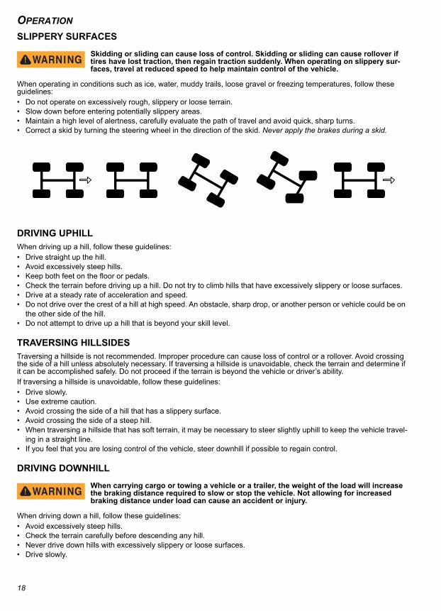
SLIPPERY SURFACESSkidding or sliding can cause loss of control. Skidding or sliding can cause rollover if tires have lost traction, then regain traction suddenly. When operating on slippery sur-faces, travel at reduced speed to help maintain control of the vehicle.
When operating in conditions such as ice, water, muddy trails, loose gravel or freezing temperatures, follow these guidelines:• Do not operate on excessively rough, slippery or loose terrain.• Slow down before entering potentially slippery areas.• Maintain a high level of alertness, carefully evaluate the path of travel and avoid quick, sharp turns.• Correct a skid by turning the steering wheel in the direction of the skid. Never apply the brakes during a skid.
DRIVING UPHILL When driving up a hill, follow these guidelines:• Drive straight up the hill.• Avoid excessively steep hills.• Keep both feet on the floor or pedals.• Check the terrain before driving up a hill. Do not try to climb hills that have excessively slippery or loose surfaces.• Drive at a steady rate of acceleration and speed.• Do not drive over the crest of a hill at high speed. An obstacle, sharp drop, or another person or vehicle could be on
the other side of the hill.• Do not attempt to drive up a hill that is beyond your skill level.
TRAVERSING HILLSIDESTraversing a hillside is not recommended. Improper procedure can cause loss of control or a rollover. Avoid crossing the side of a hill unless absolutely necessary. If traversing a hillside is unavoidable, check the terrain and determine if it can be accomplished safely. Do not proceed if the terrain is beyond the vehicle or driver’s ability.If traversing a hillside is unavoidable, follow these guidelines:• Drive slowly.• Use extreme caution.• Avoid crossing the side of a hill that has a slippery surface.• Avoid crossing the side of a steep hill.• When traversing a hillside that has soft terrain, it may be necessary to steer slightly uphill to keep the vehicle travel-
ing in a straight line.• If you feel that you are losing control of the vehicle, steer downhill if possible to regain control.
DRIVING DOWNHILL
When carrying cargo or towing a vehicle or a trailer, the weight of the load will increase the braking distance required to slow or stop the vehicle. Not allowing for increased braking distance under load can cause an accident or injury.
When driving down a hill, follow these guidelines:• Avoid excessively steep hills.• Check the terrain carefully before descending any hill.• Never drive down hills with excessively slippery or loose surfaces.• Drive slowly.
18
OPERATION
• Drive straight down the hill. Avoid descending the hill at an angle that could cause the vehicle to lean sharply to oneside.• Apply light and constant pressure to the accelerator to maintain slow speed and control of the vehicle.
STALLING ON A HILLA rollover can result from stalling or rolling backward while climbing a hill. Drive uphill at a constant speed.If your vehicle completely stalls while climbing a hill:1. Apply the brakes.2. Verify that the area behind you is clear.3. Put the vehicle in R (reverse).4. Use steady accelerator pressure to control speed, and allow the vehicle to slowly roll straight downhill.
DRIVING IN REVERSEWhen driving in reverse, follow these guidelines:• Check that the area behind the vehicle is clear of obstacles and people.• Check left and right fields of vision before driving in reverse.• Drive in reverse slowly.• Press the brakes lightly for stopping.• Accelerate slow and steady.• Avoid turning at sharp angles.
PARKING THE VEHICLENOTICE: Park the vehicle on a flat surface if possible. If parking on an incline is unavoidable, be sure to
chock the wheels to keep the vehicle from rolling.1. Press the brake to stop the vehicle.2. Turn the key switch to OFF.3. Remove the key from the key switch to prevent unauthorized use.
Maximum Weight Capacity
• Do not exceed the maximum cargo load capacity.• Do not exceed the maximum vehicle weight capacity (includes weight of operator, passenger, cargo and accesso-
ries).
Maximum Vehicle Weight Capacity 800 lbs. (363 kg)
Maximum Towing Capacity 3 E-Z-GO ELiTE golf cars
19

OPERATION
20
MAINTENANCE
MAINTENANCEMAINTENANCE SAFETY
To prevent serious injury or death, follow the procedures and comply with the safety information in this manual while performing vehicle service or maintenance.
Do not remove the cover from the battery module(s). There are no serviceable items below the cover.
Use the tools shown in the tool list and wear the specified safety equipment when per-forming vehicle service or maintenance.
Remove all jewelry before you service the vehicle.
Do not allow loose clothing or hair to contact the moving parts.
Do not touch hot objects.
Before you disconnect or connect a battery module or any other wires, ensure the key is in the OFF position.
The drive wheels must be lifted and supported on jack stands before you do any service to the power-train when the motor is in operation.
Support the vehicle with jack stands. NEVER get under a vehicle that is only supported by a jack. Lift the vehicle according to the manufacturers instructions.
Wear a face shield when working around the battery pack.
Be careful when working around batteries, using solvents or compressed air.
Use insulated tools within the battery area to prevent sparks or battery explosion.
To prevent the risk of battery explosion, keep all flammable materials, open flames or sparks away from the battery.
Maintain constant awareness that some components are heavy, spring loaded, corro-sive, explosive, can cause high amperage or get extremely hot.
After you make repairs or do maintenance, test the vehicle in a safe area that is free from vehicle and pedestrian traffic.
NOTICE: To decrease the risk of damage to the controller or motor, move the run/tow switch to the TOW posi-tion before you tow the vehicle.
An E-Z-GO ELiTE golf car cannot be used to tow E-Z-GO vehicles with lead acid batteries. The ELiTE golf car can tow up to three ELiTE model golf cars properly equipped with an approved tow bar sys-tem.
Never tow an E-Z-GO vehicle with any vehicle except an E-Z-GO golf car with an approved tow bar system.
After you connect a battery or any other wires, wait a minimum of 30 seconds before you move the switch to the RUN position.
SCHEDULED MAINTENANCEConsistent inspection, adjustment and lubrication of some components are necessary to maintain your vehicle so that it remains in safe and reliable condition. Refer to the SCHEDULED MAINTENANCE CHART on page 22 for detailed requirements. Inspect, clean, lubricate, adjust and replace parts as necessary. Use OEM or equivalent replacement parts.Record the maintenance items performed, along with details in the MAINTENANCE LOG beginning on page 37.
NOTICE: Service and adjustments are important for safe and reliable vehicle operation. If not familiar with safe service and adjustment procedures, have your dealer perform the operations.
21
MAINTENANCE
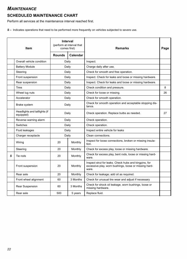
SCHEDULED MAINTENANCE CHARTPerform all services at the maintenance interval reached first.S – Indicates operations that need to be performed more frequently on vehicles subjected to severe use.
Item
Interval(perform at interval that
comes first) Remarks Page
Rounds Calendar
Overall vehicle condition Daily Inspect.
Battery Module Daily Charge daily after use.
Steering Daily Check for smooth and free operation.
Front suspension Daily Inspect. Check for leaks and loose or missing hardware.
Rear suspension Daily Inspect. Check for leaks and loose or missing hardware.
Tires Daily Check condition and pressure. 8
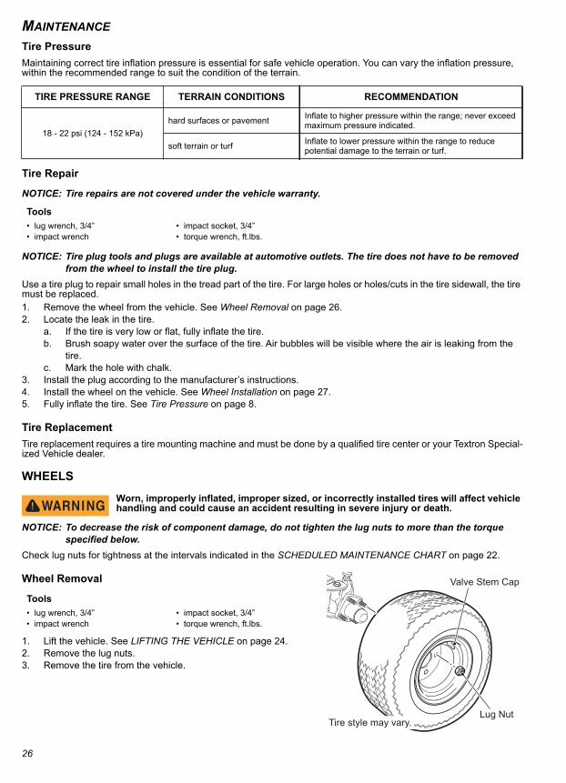
Wheel lug nuts Daily Check for loose or missing. 26
Accelerator Daily Check for smooth operation.
Brake system Daily Check for smooth operation and acceptable stopping dis-tance.
Headlights and taillights (if equipped) Daily Check operation. Replace bulbs as needed. 27
Reverse warning alarm Daily Check operation.
Switches Daily Check operation.
Fluid leakages Daily Inspect entire vehicle for leaks
Charger receptacle Daily Clean connections.
Wiring 20 Monthly Inspect for loose connections, broken or missing insula-tion.
Steering 20 Monthly Check for excess play, loose or missing hardware.
S Tie rods 20 Monthly Check for excess play, bent rods, loose or missing hard-ware.
Front suspension 20 MonthlyInspect strut for leaks. Check hubs and kingpins, for excessive play, worn bushings, loose or missing hard-ware.
Rear axle 20 Monthly Check for leakage; add oil as required.
Front wheel alignment 60 3 Months Check for unusual tire wear and adjust if necessary
Rear Suspension 60 3 Months Check for shock oil leakage, worn bushings, loose or missing hardware.
Rear axle 500 5 years Replace fluid.
22

MAINTENANCE
RECOMMENDED LUBRICANTS AND FLUIDSCheck and lubricate all components at the intervals shown in the SCHEDULED MAINTENANCE CHART beginning on page 22.REPLACEMENT OF MAINTENANCE ITEMSThese items or their equivalents can be purchased through your dealer, directly from TSV or any other qualified source.
Item Capacity Lubricants/Fluids
Rear axle oil 25 oz. (740 ml) Mobil - 424 - W - ED TSV Part Number 603967
Friction Modifier 2 oz. (60 ml) Sturaco TSV Part Number 611242
Item Part Number
10 A ATC Fuse 35212G07
Headlight Bulb 894 74004G01
Turn Signal Bulb 912-NA 74005G01
Taillight Bulb 2057 604311
23
MAINTENANCE
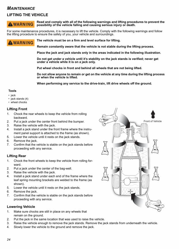
LIFTING THE VEHICLERead and comply with all of the following warnings and lifting procedures to prevent the possibility of the vehicle falling and causing serious injury or death.
For some maintenance procedures, it is necessary to lift the vehicle. Comply with the following warnings and follow the lifting procedure to ensure the safety of you, your vehicle and surroundings.
The vehicle must be on a firm and level surface for lifting.
Remain constantly aware that the vehicle is not stable during the lifting process.
Place the jack and jack stands only in the areas indicated in the following illustration.
Do not get under a vehicle until it’s stability on the jack stands is verified; never get under a vehicle while it is on a jack only.
Put wheel chocks in front and behind all wheels that are not being lifted.
Do not allow anyone to remain or get on the vehicle at any time during the lifting process or when the vehicle is lifted.
When performing any service to the drive-train, lift drive wheels off the ground.
Lifting Front 1. Chock the rear wheels to keep the vehicle from rolling
backward.2. Put a jack under the center front behind the bumper.3. Raise the vehicle with the jack.4. Install a jack stand under the front frame where the instru-
ment panel support is attached to the frame (as shown).5. Lower the vehicle until it rests on the jack stands.6. Remove the jack.7. Confirm that the vehicle is stable on the jack stands before
proceeding with any service.
Lifting Rear1. Chock the front wheels to keep the vehicle from rolling for-
ward.2. Put a jack under the center of the bag-well.3. Raise the vehicle with the jack.4. Install a jack stand under each end of the frame where the
leaf spring mounting brackets are welded to the frame (as shown).
5. Lower the vehicle until it rests on the jack stands.6. Remove the jack.7. Confirm that the vehicle is stable on the jack stands before
proceeding with any service.
Lowering Vehicle1. Make sure chocks are still in place on any wheels that
remain on the ground.2. Put the jack in the same location that was used to raise the vehicle.3. Raise the vehicle enough to remove the jack stands. Remove the jack stands from underneath the vehicle.4. Slowly lower the vehicle to the ground and remove the jack.
Tools• jack• jack stands (4)• wheel chocks
Front of Vehicle
24
MAINTENANCE
VEHICLE CLEANING AND CAREKeeping your vehicle clean is not only beneficial to its appearance, but can also help extend the life of various compo-nents.Washing the Vehicle
NOTICE: Do not use more than 700 psi pressure to wash your vehicle. High water pressure can damage com-ponents.
Some products, including insect repellents and chemicals, will damage plastic surfaces. Do not allow these types of products to contact the vehicle.
• Do not use more than 700 psi pressure to clean the vehicle.• Use an automotive type cleaner or mild soap to wash the vehicle. Harsh cleaners can scratch the finish.• Use clean or new cloths and pads for washing. Reused cloths and pads can contain dirt particles that will scratch
the finish.• Inspect all grease fittings for dirt intrusion or lack of grease after washing. Apply grease as required to maintain
proper function.• Use a sponge or soft brush and a soap/water solution to clean the vinyl seats. Rinse with clean water.• Use an automotive type wash cloth to wash the body of the vehicle. To prevent the soap from drying on the vehicle,
rinse with clean water frequently.• Clean the windshield with water and a clean cloth. Remove small scratches with a plastic polish.• Clean the bottom of the vehicle where mud or dirt can collect. Loosen any packed sediment to help with removal.
Be careful not to damage the paint.• Dry the vehicle with a chamois before the water dries to prevent water spots.
Polishing the Vehicle• Do not use medium to heavy duty compounds on the finish. Use wax that is for clear coat automotive finishes only.
Do not apply wax or polish to matte finish surfaces.• Use clean or new cloths and pads for polishing. Old or reused cloths and pads can contain dirt particles that will
scratch the finish.
TIRESFollow the tire maintenance procedures as instructed in this manual and on the labels on the vehicle.Always use approved size and type of replacement tires. See VEHICLE SPECIFICATIONS on page 34.
Worn, improperly inflated, improper sized, or incorrectly installed tires will affect vehicle handling and could cause an accident resulting in severe injury or death.
Inflate all tires to the same pressure. Operating with unequal or incorrect pressure can adversely affect steering and handling and could cause an accident resulting in severe injury or death.
To decrease the risk of tire explosion, do not exceed the tire inflation rating on the tire sidewall. Make sure the tires are properly inflated at all times of operation.
To decrease the risk of tire explosion, inflate small amounts of air into the tire at intervals to allow the beads to seat properly. Because of the low volume of the small tires, over inflation can occur in seconds. Never exceed the tire inflation pressure rating on the tire sidewall when seating a bead. Protect your face and eyes when you remove a valve core.
When you remove the wheels, use only sockets made for impact wrenches to decrease the risk of injury by a broken socket.
Do not use tires with low rated pressure. Do not use tires that have a recommended tire inflation pressure less than the tire inflation pressure recommended in the owner’s guide.
Do not over inflate the tires. Excess pressure can cause the tire to separate from the wheel or cause a tire explosion.
25
MAINTENANCE
Tire PressureMaintaining correct tire inflation pressure is essential for safe vehicle operation. You can vary the inflation pressure, within the recommended range to suit the condition of the terrain.Tire Repair
NOTICE: Tire repairs are not covered under the vehicle warranty.
NOTICE: Tire plug tools and plugs are available at automotive outlets. The tire does not have to be removed from the wheel to install the tire plug.
Use a tire plug to repair small holes in the tread part of the tire. For large holes or holes/cuts in the tire sidewall, the tire must be replaced.1. Remove the wheel from the vehicle. See Wheel Removal on page 26.2. Locate the leak in the tire.
a. If the tire is very low or flat, fully inflate the tire.b. Brush soapy water over the surface of the tire. Air bubbles will be visible where the air is leaking from the
tire.c. Mark the hole with chalk.
3. Install the plug according to the manufacturer’s instructions.4. Install the wheel on the vehicle. See Wheel Installation on page 27.5. Fully inflate the tire. See Tire Pressure on page 8.
Tire ReplacementTire replacement requires a tire mounting machine and must be done by a qualified tire center or your Textron Special-ized Vehicle dealer.
WHEELS
Worn, improperly inflated, improper sized, or incorrectly installed tires will affect vehicle handling and could cause an accident resulting in severe injury or death.
NOTICE: To decrease the risk of component damage, do not tighten the lug nuts to more than the torque specified below.
Check lug nuts for tightness at the intervals indicated in the SCHEDULED MAINTENANCE CHART on page 22.
Wheel Removal
1. Lift the vehicle. See LIFTING THE VEHICLE on page 24.2. Remove the lug nuts.3. Remove the tire from the vehicle.
TIRE PRESSURE RANGE TERRAIN CONDITIONS RECOMMENDATION
18 - 22 psi (124 - 152 kPa)hard surfaces or pavement Inflate to higher pressure within the range; never exceed
maximum pressure indicated.
soft terrain or turf Inflate to lower pressure within the range to reduce potential damage to the terrain or turf.
Tools• lug wrench, 3/4” • impact socket, 3/4”• impact wrench • torque wrench, ft.lbs.
Tools• lug wrench, 3/4” • impact socket, 3/4”• impact wrench • torque wrench, ft.lbs.
Valve Stem Cap
Tire style may vary.Lug Nut
26
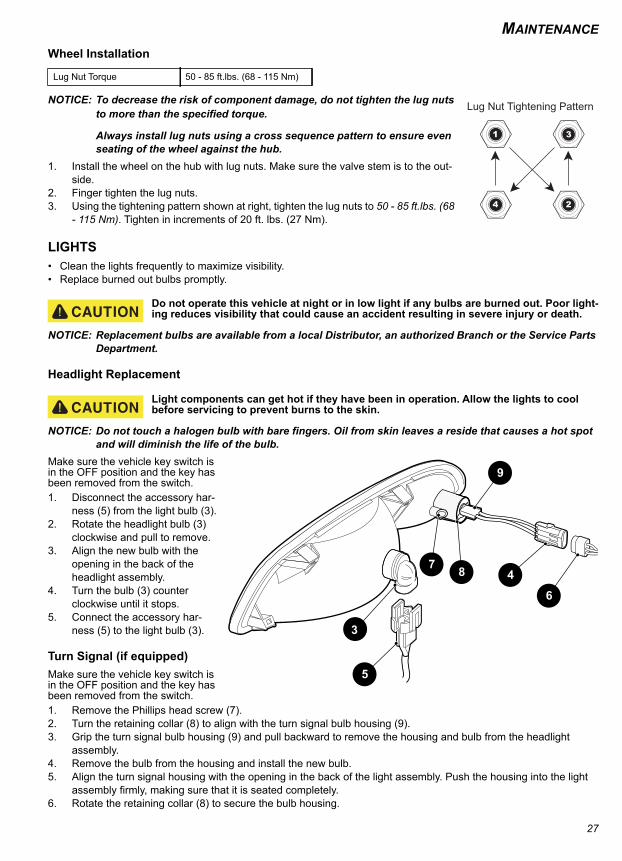
MAINTENANCE
Wheel Installation
NOTICE: To decrease the risk of component damage, do not tighten the lug nuts to more than the specified torque.
Always install lug nuts using a cross sequence pattern to ensure even seating of the wheel against the hub.
1. Install the wheel on the hub with lug nuts. Make sure the valve stem is to the out-side.
2. Finger tighten the lug nuts.3. Using the tightening pattern shown at right, tighten the lug nuts to 50 - 85 ft.lbs. (68
- 115 Nm). Tighten in increments of 20 ft. lbs. (27 Nm).
LIGHTS• Clean the lights frequently to maximize visibility.• Replace burned out bulbs promptly.
Do not operate this vehicle at night or in low light if any bulbs are burned out. Poor light-ing reduces visibility that could cause an accident resulting in severe injury or death.
NOTICE: Replacement bulbs are available from a local Distributor, an authorized Branch or the Service Parts Department.
Headlight Replacement
Light components can get hot if they have been in operation. Allow the lights to cool before servicing to prevent burns to the skin.
NOTICE: Do not touch a halogen bulb with bare fingers. Oil from skin leaves a reside that causes a hot spot and will diminish the life of the bulb.
Make sure the vehicle key switch is in the OFF position and the key has been removed from the switch.1. Disconnect the accessory har-
ness (5) from the light bulb (3).2. Rotate the headlight bulb (3)
clockwise and pull to remove.3. Align the new bulb with the
opening in the back of the headlight assembly.
4. Turn the bulb (3) counter clockwise until it stops.
5. Connect the accessory har-ness (5) to the light bulb (3).
Turn Signal (if equipped)Make sure the vehicle key switch is in the OFF position and the key has been removed from the switch.1. Remove the Phillips head screw (7).2. Turn the retaining collar (8) to align with the turn signal bulb housing (9).3. Grip the turn signal bulb housing (9) and pull backward to remove the housing and bulb from the headlight
assembly.4. Remove the bulb from the housing and install the new bulb.5. Align the turn signal housing with the opening in the back of the light assembly. Push the housing into the light
assembly firmly, making sure that it is seated completely.6. Rotate the retaining collar (8) to secure the bulb housing.
Lug Nut Torque 50 - 85 ft.lbs. (68 - 115 Nm)
Lug Nut Tightening Pattern
3
5
47 8
9
6
27
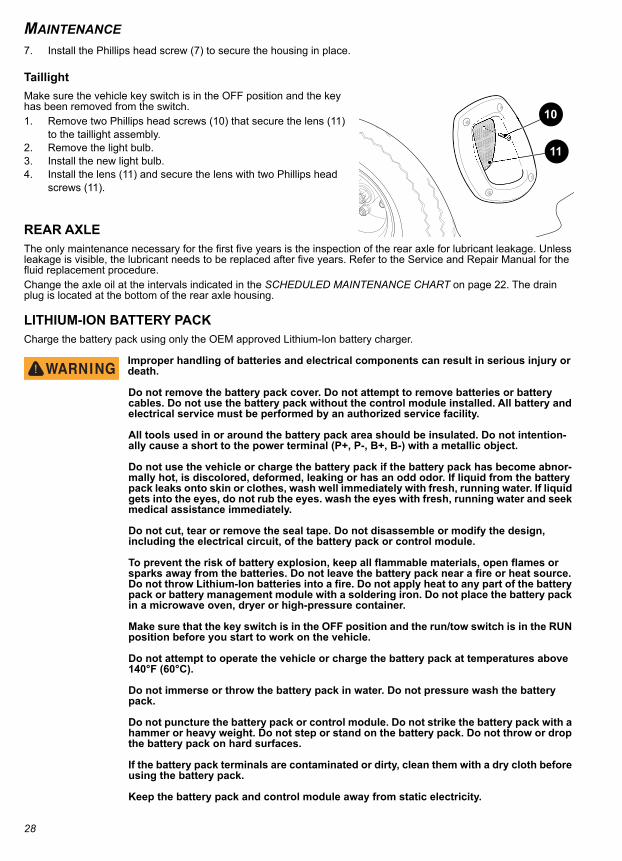
MAINTENANCE
7. Install the Phillips head screw (7) to secure the housing in place.TaillightMake sure the vehicle key switch is in the OFF position and the key has been removed from the switch.1. Remove two Phillips head screws (10) that secure the lens (11)
to the taillight assembly.2. Remove the light bulb.3. Install the new light bulb.4. Install the lens (11) and secure the lens with two Phillips head
screws (11).
REAR AXLE The only maintenance necessary for the first five years is the inspection of the rear axle for lubricant leakage. Unless leakage is visible, the lubricant needs to be replaced after five years. Refer to the Service and Repair Manual for the fluid replacement procedure.Change the axle oil at the intervals indicated in the SCHEDULED MAINTENANCE CHART on page 22. The drain plug is located at the bottom of the rear axle housing.
LITHIUM-ION BATTERY PACKCharge the battery pack using only the OEM approved Lithium-Ion battery charger.
Improper handling of batteries and electrical components can result in serious injury or death.
Do not remove the battery pack cover. Do not attempt to remove batteries or battery cables. Do not use the battery pack without the control module installed. All battery and electrical service must be performed by an authorized service facility.
All tools used in or around the battery pack area should be insulated. Do not intention-ally cause a short to the power terminal (P+, P-, B+, B-) with a metallic object.
Do not use the vehicle or charge the battery pack if the battery pack has become abnor-mally hot, is discolored, deformed, leaking or has an odd odor. If liquid from the battery pack leaks onto skin or clothes, wash well immediately with fresh, running water. If liquid gets into the eyes, do not rub the eyes. wash the eyes with fresh, running water and seek medical assistance immediately.
Do not cut, tear or remove the seal tape. Do not disassemble or modify the design, including the electrical circuit, of the battery pack or control module.
To prevent the risk of battery explosion, keep all flammable materials, open flames or sparks away from the batteries. Do not leave the battery pack near a fire or heat source. Do not throw Lithium-Ion batteries into a fire. Do not apply heat to any part of the battery pack or battery management module with a soldering iron. Do not place the battery pack in a microwave oven, dryer or high-pressure container.
Make sure that the key switch is in the OFF position and the run/tow switch is in the RUN position before you start to work on the vehicle.
Do not attempt to operate the vehicle or charge the battery pack at temperatures above 140°F (60°C).
Do not immerse or throw the battery pack in water. Do not pressure wash the battery pack.
Do not puncture the battery pack or control module. Do not strike the battery pack with a hammer or heavy weight. Do not step or stand on the battery pack. Do not throw or drop the battery pack on hard surfaces.
If the battery pack terminals are contaminated or dirty, clean them with a dry cloth before using the battery pack.
Keep the battery pack and control module away from static electricity.
11
10
28
MAINTENANCE
Before recycling or shipping battery pack, make sure that the battery pack terminals are insulated.Lithium-Ion batteries are recyclable: •Return discarded batteries to distributor or manufacturer for recycling. •Contact local or state environmental department for the disposal information. •Refer to the Maintenance section for additional information.
BATTERY CHARGING AND MAINTENANCE
Do not attempt to start the vehicle or charge the battery pack if the vehicle has been stored at or below freezing temperatures.
NOTICE: Do not spray the battery module with water. Do not attempt to add water to the battery module.Do not charge the batteries if the ambient temperature is below -4°F (-20°C) or above 113°F (45°C). Refer to Appen-dix A for battery charger operating instructions.Before connecting the battery charger:
• Park the vehicle, turn the key switch to OFF and remove the key.• Inspect the charging receptacle for dirt or debris. Remove dirt or debris if found.• Inspect the charger cords and plugs for cracks or damage. Replace any damaged cords before use.• Plug the charger into a receptacle on a dedicated circuit. Do not connect any other devices to the receptacle.• Connect the charger to the vehicle.
BATTERY CHARGINGThe battery charger is designed to completely charge the battery set. If the batteries are severely deep cycled the charger will indicate a fault. The automatic charger determines the correct length of charge for the battery set and turns off when the batteries are charged. Always refer to the instructions supplied with the charger. See Appendix A for charger operating instructions.
AC VoltageThe battery charger output is directly related to the input voltage. If the vehicle receives an incomplete charge in a nor-mally adequate time period, low AC voltage can be the cause. Consult an electrician if necessary.
29
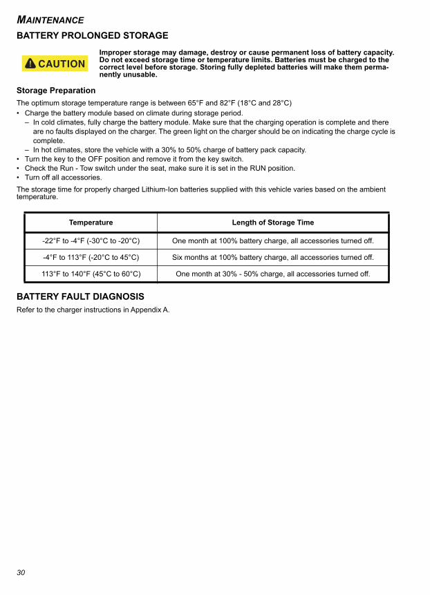
MAINTENANCE
BATTERY PROLONGED STORAGEImproper storage may damage, destroy or cause permanent loss of battery capacity. Do not exceed storage time or temperature limits. Batteries must be charged to the correct level before storage. Storing fully depleted batteries will make them perma-nently unusable.
Storage PreparationThe optimum storage temperature range is between 65°F and 82°F (18°C and 28°C)• Charge the battery module based on climate during storage period.
– In cold climates, fully charge the battery module. Make sure that the charging operation is complete and there are no faults displayed on the charger. The green light on the charger should be on indicating the charge cycle is complete.
– In hot climates, store the vehicle with a 30% to 50% charge of battery pack capacity.• Turn the key to the OFF position and remove it from the key switch.• Check the Run - Tow switch under the seat, make sure it is set in the RUN position.• Turn off all accessories.The storage time for properly charged Lithium-Ion batteries supplied with this vehicle varies based on the ambient temperature.
BATTERY FAULT DIAGNOSISRefer to the charger instructions in Appendix A.
Temperature Length of Storage Time
-22°F to -4°F (-30°C to -20°C) One month at 100% battery charge, all accessories turned off.
-4°F to 113°F (-20°C to 45°C) Six months at 100% battery charge, all accessories turned off.
113°F to 140°F (45°C to 60°C) One month at 30% - 50% charge, all accessories turned off.
30
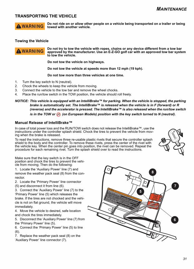
MAINTENANCE
TRANSPORTING THE VEHICLEDo not ride on or allow other people on a vehicle being transported on a trailer or being towed with another vehicle.
Towing the Vehicle
Do not try to tow the vehicle with ropes, chains or any device different from a tow bar approved by the manufacturer. Use an E-Z-GO golf car with an approved tow bar system to tow the vehicle.
Do not tow the vehicle on highways.
Do not tow the vehicle at speeds more than 12 mph (19 kph).
Do not tow more than three vehicles at one time.
1. Turn the key switch to N (neutral).2. Chock the wheels to keep the vehicle from moving.3. Connect the vehicle to the tow bar and remove the wheel chocks.4. Place the run/tow switch in the TOW position, the vehicle should roll freely.
NOTICE: This vehicle is equipped with an IntelliBrake™ for parking. When the vehicle is stopped, the parking brake is automatically set. The IntelliBrake™ is released when the vehicle is in F (forward) or R (reverse) and the accelerator is pressed. The IntelliBrake™ is also released when the run/tow switch is in the TOW or (on European Models) position with the key switch turned to N (neutral).
Manual Release of IntelliBrake™In case of total power loss and the RUN/TOW switch does not release the IntelliBrake™, use the instructions under the controller splash shield. Chock the tires to prevent the vehicle from mov-ing when the brake is released. To read the instructions, remove three re-usable plastic rivets that secure the controller splash shield to the body and the controller. To remove these rivets, press the center of the rivet with the vehicle key. When the center pin goes into position, the rivet can be removed. Repeat the procedure for each remaining rivet. Turn the splash shield over to read the instructions.
Make sure that the key switch is in the OFF position and chock the tires to prevent the vehi-cle from moving; Then do the following:1. Locate the ‘Auxiliary Power’ line (7) and remove the weather pack seal (8) from the con-nector.2. Locate the ‘Primary Power’ line connector (5) and disconnect it from line (6).3. Connect the ‘Auxiliary Power’ line (7) to the ‘Primary Power’ line (5) which releases the brake. If the tires are not chocked and the vehi-cle is not on flat ground, the vehicle will move immediately.4. Move the vehicle to desired, safe location and chock the tires immediately.5. Disconnect the ‘Auxiliary Power’ line (7) from the ‘Primary Power’ line (5).6. Connect the ‘Primary Power’ line (5) to line (6).7. Replace the weather pack seal (8) on the ‘Auxiliary Power’ line connector (7).
609694
Failure to follow these instructions can result in DEATH or SERIOUS INJURY
THIS PROCEDURE SHOULD ONLY BE TO CLEAR VEHICLE FROM AN UNSAFE AREA AND BE PERFORMED
ONLY BY QUALIFIED TRAINED PERSONNEL
In Case Of Total Power Loss And The ‘Run-tow’ Switch DOES NOT Release The Brake To Move The Vehicle:
Turn the ignition key to the ‘OFF’ position and ‘chock’ tires to prevent inadvertent movement.
Connect ‘Auxiliary Power’ line (3) to ‘Primary Power’ line (1) which will release the brake. THIS WILL
CAUSE THE VEHICLE TO MOVE IMMEDIATELY IF NOT ON LEVEL GROUND.
Move vehicle to desired location and park it properly on level ground, chock tires, IMMEDIATELY
DISCONNECT ‘AUXILIARY POWER’ AND RECONNECT ‘PRIMARY POWER’ (1, 2) FOR SAFETY
AND TO AVOID BATTERY DRAIN.
Reconnect the Weather Pack Seal (4) to the Auxiliary Power line (3) and perform required service
procedures following all Safety guidelines as outlined in your repair manual.
Identify the ‘Auxiliary Power’ line (3) and remove the Weather Pack Seal (4) from the connector.
Identify the ‘Primary Power’ line (1) connector and disconnect the line (2).
7
8
5
6
31
MAINTENANCE
8. To reinstall the controller splash shield, position the splash shield by aligning the mounting holes with the holes in the body, push the center pin of each rivet upward so that the top of the pin is above the rivet head.9. Place a rivet in each mounting hole of the controller splash shield and push down on the center pin until the top of the pin is flush with the rivet head.Hauling the Vehicle
Loose cargo or vehicle components can fly off when the vehicle is being transported. Secure or remove all cargo. Inspect the vehicle for loose components prior to transport.
Do not allow anyone on a vehicle being transported on a trailer.
Remove the windshield before you transport a vehicle on a trailer.
Maximum speed with canopy top installed is 50 mph (80 kph).
• If the vehicle is being hauled on a trailer or truck at highway speeds, the canopy top must be removed.• If the vehicle is being hauled on a trailer or truck below highway speeds, check that canopy top hardware is tight
and there are no cracks in the canopy top at the mounting points.• The rated capacity of the hauling trailer or truck must be more than the weight of the vehicle and load plus 1000 lbs.
(454 kg). See GENERAL SPECIFICATIONS for the weight of the vehicle.
1. Drive the vehicle onto the trailer or truck.2. Turn the key to the OFF position. To prevent loss of the key, remove it from the ignition switch.3. Make sure the seat(s) are secured.4. Secure the vehicle to the trailer or truck with tie downs, straps or ropes.
32

SPECIFICATIONS
VEHICLE SPECIFICATIONS
33
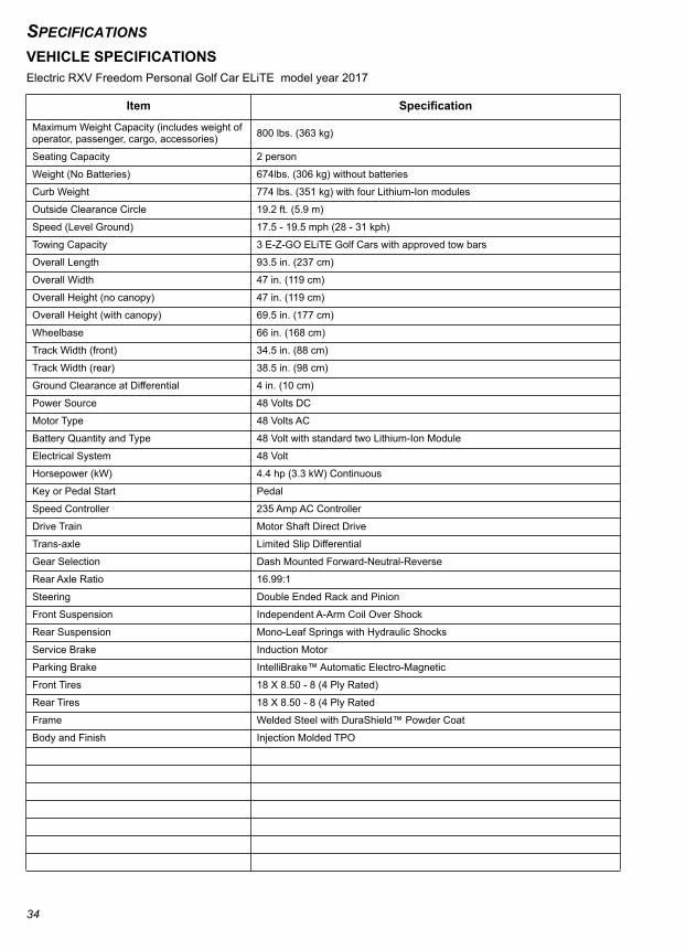
SPECIFICATIONS
VEHICLE SPECIFICATIONSElectric RXV Freedom Personal Golf Car ELiTE model year 2017Item Specification
Maximum Weight Capacity (includes weight of operator, passenger, cargo, accessories) 800 lbs. (363 kg)
Seating Capacity 2 person
Weight (No Batteries) 674lbs. (306 kg) without batteries
Curb Weight 774 lbs. (351 kg) with four Lithium-Ion modules
Outside Clearance Circle 19.2 ft. (5.9 m)
Speed (Level Ground) 17.5 - 19.5 mph (28 - 31 kph)
Towing Capacity 3 E-Z-GO ELiTE Golf Cars with approved tow bars
Overall Length 93.5 in. (237 cm)
Overall Width 47 in. (119 cm)
Overall Height (no canopy) 47 in. (119 cm)
Overall Height (with canopy) 69.5 in. (177 cm)
Wheelbase 66 in. (168 cm)
Track Width (front) 34.5 in. (88 cm)
Track Width (rear) 38.5 in. (98 cm)
Ground Clearance at Differential 4 in. (10 cm)
Power Source 48 Volts DC
Motor Type 48 Volts AC
Battery Quantity and Type 48 Volt with standard two Lithium-Ion Module
Electrical System 48 Volt
Horsepower (kW) 4.4 hp (3.3 kW) Continuous
Key or Pedal Start Pedal
Speed Controller 235 Amp AC Controller
Drive Train Motor Shaft Direct Drive
Trans-axle Limited Slip Differential
Gear Selection Dash Mounted Forward-Neutral-Reverse
Rear Axle Ratio 16.99:1
Steering Double Ended Rack and Pinion
Front Suspension Independent A-Arm Coil Over Shock
Rear Suspension Mono-Leaf Springs with Hydraulic Shocks
Service Brake Induction Motor
Parking Brake IntelliBrake™ Automatic Electro-Magnetic
Front Tires 18 X 8.50 - 8 (4 Ply Rated)
Rear Tires 18 X 8.50 - 8 (4 Ply Rated
Frame Welded Steel with DuraShield™ Powder Coat
Body and Finish Injection Molded TPO
34

SPECIFICATIONS
CE Noise, Vibration and Harshness Measurement methods were applied per the ISO 2631 and ISO 5349 standards under conditions of typical vehicle surfaces.
Noise Sound pressure: continued A-weighted equal to or less than 70 db (A)
Vibration, WBV The highest RMS value of weighted acceleration is: 1.15 m/s2
Vibration, HAV The highest RMS value of weighted acceleration is: 2.5 m/s2
The uncertainty of measurement is 0.2 m/s2
Item Specification
35

SPECIFICATIONS
36

MAINTENANCE LOG
MAINTENANCE LOGRecord periodic maintenance in the following maintenance log.
DATE MILES (KM) AND HOURS TECHNICIAN SERVICE PERFORMED
COMMENTS
37

MAINTENANCE LOG
DATE MILES (KM) AND HOURS TECHNICIAN SERVICE PERFORMED
COMMENTS
38

MAINTENANCE LOG
DATE MILES (KM) AND HOURS TECHNICIAN SERVICE PERFORMED
COMMENTS
39

MAINTENANCE LOG
DATE MILES (KM) AND HOURS TECHNICIAN SERVICE PERFORMED
COMMENTS
40

MAINTENANCE LOG
DATE MILES (KM) AND HOURS TECHNICIAN SERVICE PERFORMED
COMMENTS
41

MAINTENANCE LOG
DATE MILES (KM) AND HOURS TECHNICIAN SERVICE PERFORMED
COMMENTS
42

APPENDIX A
APPENDIX A
BATTERY CHARGER USER’S GUIDE
A-1
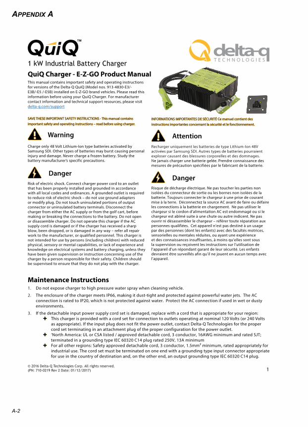
APPENDIX A
WarningCharge only 48 Volt Lithium-Ion type batteries activated by
Samsung SDI. Other types of batteries may burst causing personal
injury and damage. Never charge a frozen battery. Study the
battery manufacturer’s specific precautions.
Risk of electric shock. Connect charger power cord to an outlet
that has been properly installed and grounded in accordance
with all local codes and ordinances. A grounded outlet is required
to reduce risk of electric shock – do not use ground adapters
or modify plug. Do not touch uninsulated portions of output
connector or uninsulated battery terminals. Disconnect the
charger from either the AC supply or from the golf cart, before
making or breaking the connections to the battery. Do not open
or disassemble charger. Do not operate this charger if the AC
supply cord is damaged or if the charger has received a sharp
blow, been dropped, or is damaged in any way – refer all repair
work to the manufacturer, or qualified personnel. This charger is
not intended for use by persons (including children) with reduced
physical, sensory or mental capabilities, or lack of experience and
knowledge on electrical systems and battery charging, unless they
have been given supervision or instruction concerning use of the
charger by a person responsible for their safety. Children should
be supervised to ensure that they do not play with the charger.
Danger
Recharger uniquement les batteries de type Lithium-Ion 48V
activées par Samsung SDI. Autres types de batteries pourraient
exploser causant des blessures corporelles et des dommages.
Ne jamais charger une batterie gelée. Prendre connaissance des
mesures de précaution spécifiées par le fabricant de la batterie.
Attention
Risque de décharge électrique. Ne pas toucher les parties non
isolées du connecteur de sortie ou les bornes non isolées de la
batterie. Toujours connecter le chargeur à une prise de courant
mise à la terre. Déconnectez la source AC avant de faire ou défaire
les connections à la batterie en chargement. Ne pas utiliser le
chargeur si le cordon d’alimentation AC est endommagé ou si le
chargeur est abîmé suite à une chute ou autre indicent. Ne pas
ouvrir ni désassembler le chargeur – référer toute réparation aux
personnes qualifiées. Cet appareil n’est pas destiné à un usage
par des personnes (dont les enfants) avec des facultés motrices,
sensorielles ou mentales réduites, ou ayant une expérience
et des connaissances insuffisantes, à moins qu’elles sont sous
la supervision ou reçoivent les instructions sur l’utilisation de
l’appareil d’un répondant garant de leur sécurité. Les enfants
devraient être surveillés afin qu’il ne jouent en aucun temps avec
l’appareil.
Danger
This manual contains important safety and operating instructions
for versions of the Delta-Q QuiQ (Model nos. 913-4830-E3/-
E3B/-E5 /-E5B) installed on E-Z-GO brand vehicles. Please read this
information before using your QuiQ Charger. For manufacturer
contact information and technical support resources, please visit
delta-q.com/support
QuiQ Charger - E-Z-GO Product Manual
© 2016 Delta-Q Technologies Corp. All rights reserved.(PN: 710-0219 Rev 2 Date: 01/12/2017) 1
1 kW Industrial Battery Charger
Maintenance Instructions1. Do not expose charger to high pressure water spray when cleaning vehicle.
2. The enclosure of the charger meets IP66, making it dust-tight and protected against powerful water jets. The AC
connection is rated to IP20, which is not protected against water. Protect the AC connection if used in wet or dusty
environments.
3. If the detachable input power supply cord set is damaged, replace with a cord that is appropriate for your region:
This charger is provided with a cord set for connection to outlets operating at nominal 120 Volts (or 240 Volts
as appropriate). If the input plug does not fit the power outlet, contact Delta-Q Technologies for the proper
cord set terminating in an attachment plug of the proper configuration for the power outlet.
‘North America: UL or CSA listed / approved detachable cord, 3 conductor, 16AWG minimum and rated SJT;
terminated in a grounding type IEC 60320 C14 plug rated 250V, 13A minimum
For all other regions: Safety approved detachable cord, 3 conductor, 1.5mm² minimum, rated appropriately for
industrial use. The cord set must be terminated on one end with a grounding type input connector appropriate
for use in the country of destination and, on the other end, an output grounding type IEC 60320 C14 plug.
SAVE THESE IMPORTANT SAFETY INSTRUCTIONS - This manual contains
important safety and operating instructions – read before using charger.
INFORMATIONS IMPORTANTES DE SÉCURITÉ Ce manuel contient des
instructions importantes concernant la sécurité et le fonctionnement.
A-2
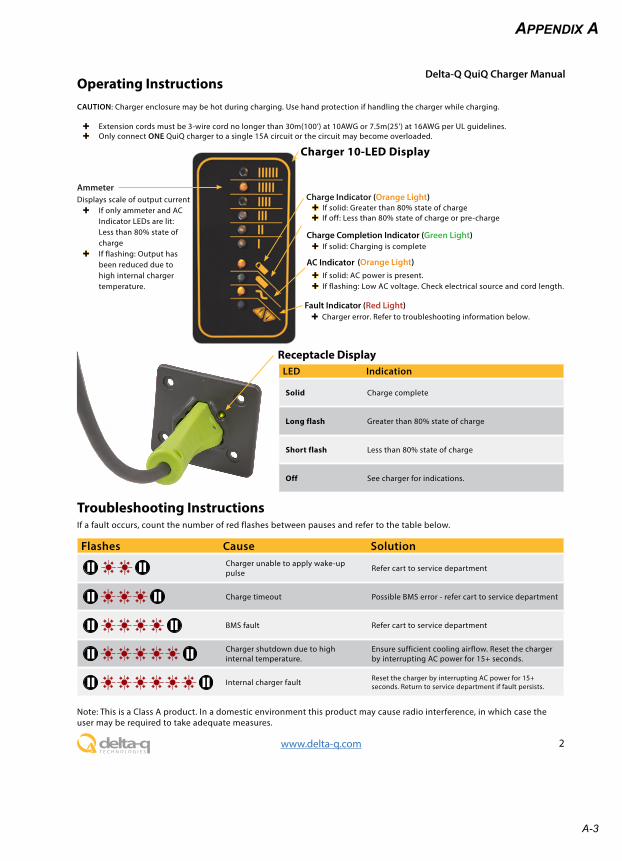
APPENDIX A
Operating Instructions
Receptacle Display
CAUTION: Charger enclosure may be hot during charging. Use hand protection if handling the charger while charging.
Extension cords must be 3-wire cord no longer than 30m(100’) at 10AWG or 7.5m(25’) at 16AWG per UL guidelines.
Only connect ONE QuiQ charger to a single 15A circuit or the circuit may become overloaded.
Delta-Q QuiQ Charger Manual
2www.delta-q.com
Fault Indicator (Red Light) Charger error. Refer to troubleshooting information below.
If solid: AC power is present.
If flashing: Low AC voltage. Check electrical source and cord length.
AC Indicator
Charge Indicator (Orange Light) If solid: Greater than 80% state of charge
Charge Completion Indicator (Green Light) If solid: Charging is complete
Displays scale of output current
If only ammeter and AC
Indicator LEDs are lit:
Less than 80% state of
charge
If flashing: Output has
been reduced due to
high internal charger
temperature.
Ammeter
Troubleshooting InstructionsIf a fault occurs, count the number of red flashes between pauses and refer to the table below.
LED Indication
Solid Charge complete
Long flash Greater than 80% state of charge
Short flash Less than 80% state of charge
Off See charger for indications.
Flashes Cause SolutionCharger unable to apply wake-up
pulseRefer cart to service department
Charge timeout Possible BMS error - refer cart to service department
BMS fault Refer cart to service department
Charger shutdown due to high
internal temperature.
Ensure sufficient cooling airflow. Reset the charger
by interrupting AC power for 15+ seconds.
Internal charger faultReset the charger by interrupting AC power for 15+
seconds. Return to service department if fault persists.
Note: This is a Class A product. In a domestic environment this product may cause radio interference, in which case the
user may be required to take adequate measures.
Charger 10-LED Display
(Orange Light)
If off: Less than 80% state of charge or pre-charge
A-3

A-4
APPENDIX A

APPENDIX B
APPENDIX B
DECLARATION OF CONFORMITY
B-1
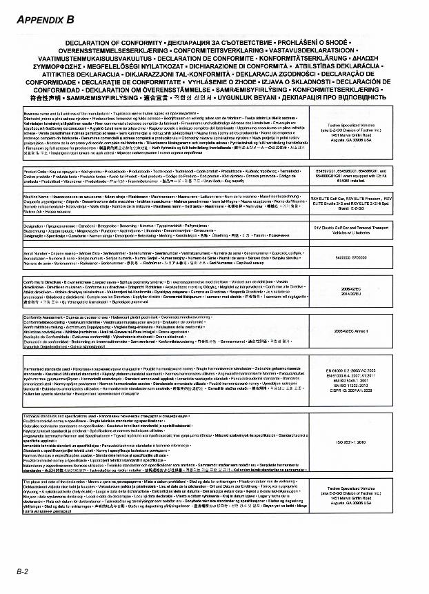
APPENDIX B
B-2
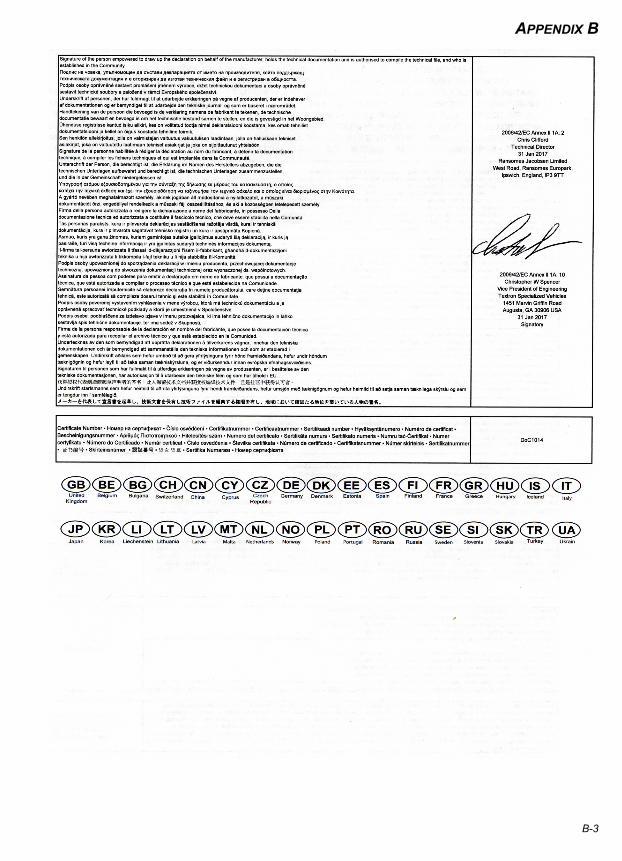
APPENDIX B
B-3

B-4
APPENDIX B
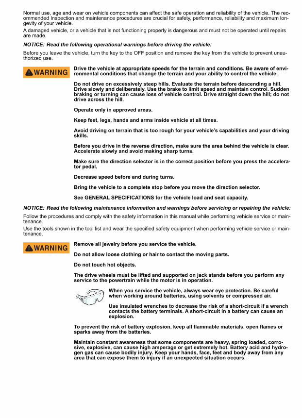
Normal use, age and wear on vehicle components can affect the safe operation and reliability of the vehicle. The rec-ommended Inspection and maintenance procedures are crucial for safety, performance, reliability and maximum lon-gevity of your vehicle.A damaged vehicle, or a vehicle that is not functioning properly is dangerous and must not be operated until repairs are made.
NOTICE: Read the following operational warnings before driving the vehicle:Before you leave the vehicle, turn the key to the OFF position and remove the key from the vehicle to prevent unau-thorized use.
Drive the vehicle at appropriate speeds for the terrain and conditions. Be aware of envi-ronmental conditions that change the terrain and your ability to control the vehicle.
Do not drive on excessively steep hills. Evaluate the terrain before descending a hill. Drive slowly and deliberately. Use the brake to limit speed and maintain control. Sudden braking or turning can cause loss of vehicle control. Drive straight down the hill; do not drive across the hill.
Operate only in approved areas.
Keep feet, legs, hands and arms inside vehicle at all times.
Avoid driving on terrain that is too rough for your vehicle’s capabilities and your driving skills.
Before you drive in the reverse direction, make sure the area behind the vehicle is clear. Accelerate slowly and avoid making sharp turns.
Make sure the direction selector is in the correct position before you press the accelera-tor pedal.
Decrease speed before and during turns.
Bring the vehicle to a complete stop before you move the direction selector.
See GENERAL SPECIFICATIONS for the vehicle load and seat capacity.
NOTICE: Read the following maintenance information and warnings before servicing or repairing the vehicle:Follow the procedures and comply with the safety information in this manual while performing vehicle service or main-tenance.Use the tools shown in the tool list and wear the specified safety equipment when performing vehicle service or main-tenance.
Remove all jewelry before you service the vehicle.
Do not allow loose clothing or hair to contact the moving parts.
Do not touch hot objects.
The drive wheels must be lifted and supported on jack stands before you perform any service to the powertrain while the motor is in operation.
When you service the vehicle, always wear eye protection. Be careful when working around batteries, using solvents or compressed air.
Use insulated wrenches to decrease the risk of a short-circuit if a wrench contacts the battery terminals. A short-circuit in a battery can cause an explosion.
To prevent the risk of battery explosion, keep all flammable materials, open flames or sparks away from the batteries.
Maintain constant awareness that some components are heavy, spring loaded, corro-sive, explosive, can cause high amperage or get extremely hot. Battery acid and hydro-gen gas can cause bodily injury. Keep your hands, face, feet and body away from any area that can expose them to injury if an unexpected situation occurs.
Textron Specialized Vehicles, Inc.1451 Marvin Griffin Road Augusta, Georgia 30906 - 3852 USA
CONTACT INFORMATIONNorth America:Technical Assistance & Warranty Phone: 1-800-774-3946, FAX: 1-800-448-8124Service Parts Phone: 1-888-GET-E-Z-GO (1-888-438-3946), FAX: 1-800-752-6175
International: Phone: 001-706-798-4311, FAX: 001-706-771-4609
Parts Manuals and Repair Manuals are available from a local Distributor, an authorized Branch, Genuine E-Z-GO Parts & Accessories Department or at www.shopezgo.com.
Copyrighted MaterialThis manual may not be reproduced in whole or in
part without the express permission ofTSV (Augusta),
Technical Communications Department


![7 rxv 5355 OCH. [O]ÞI MOT. PPGATAN • E-CIMET. I](https://img.pdfslide.net/doc/110x75/619d5407e64b7d703e263043/7-rxv-5355-och-oi-mot-ppgatan-e-cimet-i.jpg)