Embed Size (px)
DESCRIPTION
Kyle Type E Recloser Maintenance
Citation preview

Figure 1.Type E single-phase, hydraulically con-trolled oil circuit recloser.
Figure 2.The non-reclosing feature is set with a handle under the sleet hood (see arrow).Whenthe handle is down (left), the recloser will trip on overcurrent and lock out without re-closing.When the handle is up (right), the recloser will operate according to its intern-ally set program.
These instructions do not claim to cover all details or variations in the equipment, procedure, or process described, nor to provide direction for meet-ing every possible contingency during installation, operation, or maintenance. When additional information is desired to satisfy a problem not coveredsufficiently for the user’s purpose, please contact your Cooper Power Systems sales engineer.
June 1984 • Supersedes 12/82
ReclosersService Information
S280-25-5Type EMaintenance Instructions
1
CONTENTSIntroduction ........................................1Description ..........................................1Specifications and Ratings ...............3General Maintenance Information......3
Oil Condition .....................................3Maintenance Intervals .......................3Oil Dielectric Strength .......................3
Periodic Inspectionand Maintenance .............................3
Shop Maintenance ..............................4Arc Interrupting Assembly .................4Series-Trip Solenoid
Disassembly....................................6Series-Trip Solenoid
Reassembly ....................................6Hydraulic Mechanism ........................9Changing Time-Current
Settings ........................................14Changing Operating Sequence .......14Sequence Adjustments ...................14Bushings .........................................15Head Mechanism ............................16
INTRODUCTIONService Information S280-25-5 covers themaintenance instructions for the Type Ehydraulically controlled, single-phase, oilinterrupting recloser. The manual includes ageneral description of the recloser and itsoperating principles and instructions for peri-odic inspection, testing, and shop repairs.Service parts lists keyed to exploded-viewdrawings of the unit, along with orderinginformation, are included in the manual.
DESCRIPTIONA Type E hydraulically controlled, oil-inter-rupting recloser (Figure 1) is a self-containeddevice that senses and interrupts fault cur-rents on a single phase of a distribution line.The recloser automatically recloses and, ifthe fault is temporary, restores service. If thefault is permanent, the recloser locks openafter one, two, three or four operations,depending upon its setting. Automatic reset-ting of this device enables it to distinguishbetween permanent and temporary faults.Thus, if a fault is temporary, the recloserresets and is then ready for a completesequence should another fault occur.
Operating sequences of the reclosercan be all fast, all delayed, or a combina-tion of fast followed by delayed opera-tions. Furthermore, any one of three delaycurves can be used to assure coordina-tion with other reclosers or protectivedevices. On coordinated systems, fastrecloser operations are used to clear tem-porary fault currents before branch-linefuses are damaged. Subsequentdelayed openings allow time for fault cur-rents to be cleared by branch-line fuses.Outages caused by permanent faults arethereby confined to shorter sections ofline.
Tripping is initiated by a series-con-nected coil. Current-carrying and inter-rupting capacities vary with the operatingcoil’s rating, which is selected to meetcircuit requirements. A non-reclosing fea-ture (Figure 2), standard on all CooperPower System's reclosers, is set with ahookstick-operated lever for one opera-tion to lockout without removing therecloser from service.
Applicable to Serial Numbers 52000 and above.
NOTICE: This bulletin is also applicable to Kyle productserial numbers beginning with the prefix CP57.
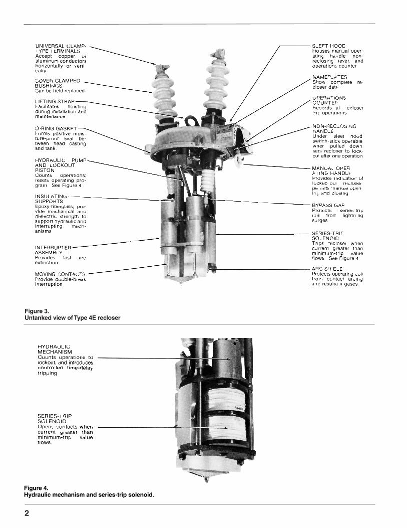
Figure 3.Untanked view of Type 4E recloser
2
Figure 4.Hydraulic mechanism and series-trip solenoid.

Table 1Specifications
Nominal operating voltage(rms kV) ............................... 24.9
Maximum design voltage(rms kV)......................................... 27
Impulse withstand (BIL),1.2 X 50 µsec wave (crest kV)..........150
60-Hz withstanding (rms kV)Dry, one minute................................ 60Wet, ten seconds.............................. 50
Reclosing time (see)............................ 2Bushing creepage distance (in.).....13-5/8
S280-25-5
SPECIFICATIONS ANDRATINGS
3. Remove mechanism from tank.Loosen four bolts that secure the tank tothe head casting, and loosen the gasketseal between tank and head casting. Thegasket seal can be broken by carefullyprying apart the head and tank. Hoist themechanism out of the tank; allow oil todrain.
4. Clean all internal components.A. Remove all traces of carbon by wiping
with a clean, lint-free cloth.B. Flush mechanism with clean, dry
transformer oil.
CAUTIONNever use volatile solutions, detergents, or water-soluble cleaners
3
Figure 5.Moving contact assembly.Background: After severe duty.Foreground: New
Trip-Coil Minimum- InterruptingContinuous Trip Current
Current Current (rms sym(amps) (amps) amps)
5 10 30010 20 60015 30 90025 50 150035 70 210050 100 250070 140 2500
100 200 2500
Table 2Interrupting Ratings
Table 3Duty Cycles
%Inter- Maximum Number Totalrupting Circuit Unit UnitRating X/R Ratio Operations Operations
15-20 3 3245-55 5 24 6890-100 12 12
GENERALMAINTENANCEINFORMATIONType E reclosers are usually applied toincrease service continuity, reduce operatingcosts, and increase revenue. The E's highload and interrupting ratings make it suitablefor use in important substations. The Type Ecan perform at peak efficiency and providereliable circuit protection if adequate mainte-nance is performed. Maintenance is relativelyeasy and inexpensive when compared withthe savings achieved by the use of reclosers.
OIL CONDITIONOil provides the internal insulation barrier fromphase to ground, and must be replacedbefore it deteriorates below a safe dielectriclevel. Replace the oil if its dielectric strengthfalls below 22 kV.
New oil should always be filtered beforeusing, even though it is obtained from anapproved source. Passing the oil through ablotter press will remove free water and solidcontaminants such as rust, dirt, and lint. Keepaeration to a minimum during filtering to pre-vent moisture in the air from condensing inthe oil and lowering its dielectric strength.
Used oil must be treated before reusing.Filtering may remove absorbed and freewater and other contaminants to raise thedielectric strength to acceptable levels.However, filtering does not always removewater-absorbing contaminants, and thedielectric strength may fall rapidly after beingreturned to service. Therefore, the reclosershould be filled with new oil, or oil that hasbeen restored to like-new condition. Oil usedin these reclosers conforms to ASTMStandard D3487, Type 1; its property limitsare shown in Reference Data R280-90-1. OilSpecifications and Tests.
Maintenance IntervalsFrequency of maintenance depends uponlocal climatic conditions and the interruptingduty imposed on the recloser. Cooper PowerSystem's recommends the unit be complete-ly inspected, cleaned, and filled with new oilat least once each year. If the Type E oper-ates through a duty cycle in less than oneyear, periodic maintenance should be per-formed then. The NEMA standard duty cyclefor reclosers is listed in Table 3.
Oil Dielectric StrengthAlthough the Type E can go through the com-plete duty cycle without requiring an oilchange, more frequent oil changes will berequired if the majority of fault currents arenear the maximum interrupting rating. Oil thathas become contaminated with carbon andsludge, or has a dielectric strength of 22 kV orlower, should be replaced. Use only oil thatmeets the requirements for Cooper PowerSystem's switchgear. Refer to Cooper PowerSystem's Reference Data R280-90-1.
PERIODIC INSPECTIONAND MAINTENANCEEach periodic check should include at leastthe following steps:1. Bypass and remove recloser from
service.Replace with a temporary fuse or sparerecloser.
2. Inspect external components.A. Check for broken bushings, paint
scratches, or other mechanical dam-age.
B. The counter reading should be notedand entered in the recloser record.
C. Move the manual operating lever upand down to see if the counter is func-tioning properly. Leave the recloser inthe open position.
5. Inspect moving contacts.Arcing tips of the moving contacts canexperience a limited erosion beforereplacement is necessary. Contactsshould be replaced before erosion of theload-current-transfer surfaces impairstheir effectiveness.
If moving contacts appear to have fur-ther useful life, inspection of the arcinterrupter chamber and stationary con-tacts can be omitted. These componentsare designed to last at least as long asthe moving contacts.
6. Inspect interrupter and exhaust port.If the stationary contacts or fiber platesare badly eroded or burned, the com-plete stationary tube assemblies shouldbe replaced. In addition, the stationarytube assemblies should be replaced anytime the moving contacts are replaced.See the “Arc-lnterrupting Assembly” sec-tion of this manual for disassemblyinstructions.

4
Figure 6.Inspecting stationary contacts and arc-interrupting chambers.
*Fully charges and in good condition.**Can not be tested in this method.
*Fully charges and in good condition.**Can not be tested in this method.
Recloser BatteriesRating Required Cable See(amps) (Paralleled) (AWG)
5 **10 **15 **25 4 Short lengths35 4 of no. 650 4 larger70 4
100 4
7. Check the dielectric strength of theinsulating oil.A. The dielectric strength should not be
less than 22 kV when tested with a0.1-in. gap in accordance with meth-ods specified in ASTM D117.
B. Low.dielectric strength usually indi-cates the presence of water or car-bon deposits.
8. Remove old oil.If oil must be replaced, drain the tankand clean out all sludge or carbondeposits.
9. Inspect tank liners.Note that two liners are employed. Theinner liner is fibrous and readily absorbsany moisture present Soft or spongyareas indicate water has been absorbed.Replace the liner if these areas are pre-sent. The outer Iiner need areas are pre-sent. The outer Iiner need not bereplaced unless it is cracked.
Rinse the tank with clean oil, andwipe out all carbon traces with a cleanlint-free cloth.
10. Fill tank with oil.Use only new transformer oil with dielec-tric strength of al least 30 kV as mea-sured across a standard 0.1-in. gap inaccordance with methods illustrated inASTM Publication D117.
Fill the tank to the correct level with oil(8.4 gallons), indicated by a line on thefiber liner.
11. Check head gasket.Clean and examine the head gasketReplace if it is cracked, checked, cut, orotherwise damaged, or if it has beenpermanently deformed.
1 2.Replace cover and mechanism intank.
A. Wipe clean the O-ring type gasket thegasket recess in the recloser cover,and the tank gasket seal.
B. Position the four head bolts and tight-en alternately (torque head
bolts to 11 - 16 ft-lb). The covercan be rotated in steps of 90degrees with respect to the tankand its mountings.
Operate the unit manually abouteight times to be sure no airremains in the hydraulic mecha-nism.
13.Test mechanical operation.An easy, effective test can be per-formed as follows:A. Move the operating lever to the
CLOSED position and wait 4 min-utes.
B. Move the operating lever to theOPEN position and listen for open-ing of the main contacts. Thenquickly move the lever back to theCLOSED position.
C. Continue opening and closing therecloser manually until lockout isachieved. This can be determinedby listening for unlatching of thelockout mechanism and also bynoting that recloser mechanism willnot latch when the lever is movedto the CLOSED position.
This test can be used to deter-mine the number of operations tolockout. The number of fast anddelayed operations can be notedalso. Fast operations can be identi-fied because the main contacts willopen almost instantaneously whenthe operating lever is moved to theOPEN position. When delayedoperations occur, a short timeelapses between operation of thelever and opening of the contacts.
14. Direct-current testing.Use the following procedure to provethe recloser is in good operating con-dition.A. Move the operating lever to the
CLOSED position and wait 4 min-utes.
B. Connect a storage battery acrossrecloser terminals. Count the oper-ations to lockout. If the correctnumber of operations did notoccur, wait five minutes and repeatthe test. Air in the hydraulic systemcan cause incorrect operation.Refer to Tables 4 and 5 for thenumber of 6- or 12- volt batteriesto use for testing Type E reclosers.
Table 46-Volt Battery Requirements for Tripping
Table 512-Volt Battery Requirements for Tripping
Recloser BatteriesRating Required Cable Size(amps ) (Parallel ) (AWG)
5 **10 **15 225 2 Short lengths35 2 of no. 6 or70 2 larger
100 2
SHOP MAINTENANCEWhen shop maintenance or repairs are tobe performed, remove the four bolts thatsecure the tank and head casting. Trip therecloser and Iift the mechanism out of theoil and allow to drain. Operations describedin this section should be performed in thecleanest conditions possible.
NOTE: Maintenance work-except for bushingreplacement-will be simplified if the work bench(table or stand) is arranged so the mechanismcan be inverted (bushings down). Many of thefollowing figures show the recloser in this invert-ed position.
Arc-InterruptingAssemblyWhen erosion has spread close to the load-current transfer surfaces of the movingcontacts, the entire arc-interrupting assem-bly should be removed and replaced.
Follow these procedures to perform thiswork:1. Remove self-locking nut and washer
from end of contact rod( Figure 7). Thendrive out the roll pin that aligns the mov-ing contact yoke. Lift off the movingcontacts.
2. Remove the bronze capscrew, lock-washer and flat washer (right-hand tubeonly), from the end of each contacttube; remove the leads to each contacttube.
3. Remove the retaining-snap rings thatsecure the contact tubes to the movingcontact rod guide (Figure 8).
4. Remove the capscrews, lockwashersand flat washers to release the contacttube wedges (Figure 9).
5. Grasp both contact tubes near the freeends and pull apart enough to releasethe tubes from the solenoid frame(Figure 10). Remove the fiber movingcontact rod guide.
6. If further maintenance is to be per-formed, do not reassemble the inter-rupting assembly yet When reassem-bling, reverse the procedures listed inthe preceding steps 1 through 6.

5
S280-25-5
Figure 7.Removing contact yoke assembly.
Figure 8.Removing retaining-snap rings.
Figure 9.Removing contact tube wedges.
Figure 10.Removing contact tubes.
Figure 11.Cross-sectional view of contact tube.

6
Figure 12.Arc-interrupting assembly parts. See Table 6 for parts identification.
Series-TripSolenoid DisassemblyIf the series-trip coil has been damaged in anyway or if the recloser is to be changed to anew rating, the series-trip coil can be replaced.New coils, gaskets, and data plates areshipped in sealed boxes.Coils should not be exposed to air any longerthan necessary because moisture from the airmay be absorbed. When a good coil isreplaced, it should be stored in the same con-tainer in which the new one was shipped.
Observe the following procedure for dis-assembly of a series-trip solenoid:1. If the arc-interrupting assembly has not
been removed previously, observe proce-dure outlined in the”Arc-lnterruptingAssembly” section.
2. Disconnect coil leads. The long coil lead isdisconnected while removing the arc-inter-rupting assemblies. The short coil lead isdisconnected from the solenoid frame byremoving the capscrew, flatwasher, lock-washer and hex nut(Figure1 3).
3. Using a 3/4-in. box wrench, remove fourhexnuts that secure the solenoid bridgeplate. Lift this plate off as shown in Figure14. Note that a red cushion washer isattached to the plate.
4. Lift off the lower gasket,coil end upper gas-ket.
5. Remove the hex cap screw that securesthe lockwasher, bushing lead, and bypassgap to the frame.
One solenoid frame shoe will also bereleased. See Fiqure 15.
6. If necessary to remove the large dielectricshield, first unscrew the solenoid tie boltsfrom the closing solenoid side of the shield.Then remove the brass machine screws,flat washers, and lockwashers that securethe shield to the solenoid frame (Figure16). The small dielectric shield is removedby sliding it off the solenoid tie bolt on thecontact tube side of the solenoid frame(Figure 16).
Series-TripSolenoid ReassemblyIf further maintenance is to be performed, donot reassemble the solenoid yet. When thesolenoid is to be reassembled, observe the fol-lowing steps:1. If the small and/or large dielectric shields
were removed, reinstall by reversing steps6 in the “Series-Trip Solenoid DisassemblySection.”
2. Position solenoid frame shoe. Place a lock-washer on the 3/8- X 1-1/4-in. steel cap-screw and secure one bushing lead andthe bypass gap to the solenoid frame. Thiscapscrew threads into the solenoid frameshoe.
3. Place a new upper gasket on the flangedend of the trip coil. Reposition the coil andnew lower gasket; secure the bridge plate.
Table 6Parts List for Arc-Interrupting Assembly (Figure 12).
Item Catalog Description No. usedNo. No.
1 K880725324037A 3/8in.-24 brass- jam nut 22 K90033003700A 3/8in. bronze lockwasher 23 K900525039087A 3/8in. brass- flat washer 24 KA170 E1 Stationary contact assembly - - left- hand 15 KA170 E2 Stationary contact assembly- - right hand 16 KP2013A46 Retaining ring 27 KP313 E Moving contact rod guide 18 KP44L Contact wedge 29 K730101125050A 1/4in-20NC2 X 1/2in. steel-hex screw 210 K900801025000A 1/4 in. steel lockwasher 211 K900201025000A 1 /4in. steel - flat washer 212 KA181 E Moving contact assembly l13 K900201043000A 7/16in. steel - flat washer 114 K970801125081 C Roll pin - - 1/8in. X 13/16in. 115 KP2020A4 Self- locking nut - - 5/16 in -24UNC2 l

7
Figure 15.Releasing bushing lead and bypass gap.
Figure 13.Series-trip solenoid assembly.
Figure 14.Bridge plate removal.
S280-25-5
4. Secure short coil lead to the solenoidframe by means of the 3/8- X 1-1/2-in.steel hex cap screw, flat-washer, lock-washer and hex nut
6. Replace arc-interrupting structureand long-coil lead as described in the“Arc-Interrupting Assembly” section ofthis manual.

8
Figure 16.Removing large dielectric shield.
Figure 17.Parts for series-trip solenoid assembly. See Table 7 for parts identification.
Table 7Parts List for Series-Trip Assembly (Figure 17)
Item Catalog Description No. UsedNo. No.
1 KA60L-1 Coil bypass gap assembly 12 K73010113712SY Steel hex cap screw - 3/8in. - 16NC2 X 1-1/4 in. 13 K900801037000Y Steel Kantlink lockwasher - 3/8in. X 0.141 in. X
094in. 24 K730101137150A Steel hexcapscrew-3/8in.- 16NC2 X1-1/2in. 15 K900830037000A Bronze lockwasher, 3/8in. 26 K880201116037A Steel hex nut- 3/8in.- 16NC2 17 KP2090A6 Solenoid gasket, upper 18 KA67L Coil Assembly (Show coil rating by suffix
Example: KA67L100 = 100-amp coil) 19 KP2090A28 Solenoid gasket, lower 1
10 KA85L Plunger stop assembly 111 KP10L Bridge Plate 112 KP3017A49 Sleeve, long coil lead (outer) 113 KP2104A4 Sleeve, long coil (inner) 114 KP3106 Large dielectric shield 115 K721525125050A 1/4in.-20X1/2in.brass machine screw 216 K900830025000A 1/4in. bronze lockwasher 217 K900525026068A 1/4in. brass flat washer 218 KP312E1 Small dielectric shield 1

9
Figure 18.Dismantling hydraulic mechanism.
Figure 19.Removing hydraulic mechanism.
Figure 20.View of hydraulic mechanism.*Used only on solenoid frame assem-bly KA179E3
S280-25-5
Hydraulic MechanismThis mechanism should require no main-tenance, but components may bechanged to provide different operationsequences. Furthermore, removal of thismechanism may be required to gain a~cess to the head operating mechanism.
Observe the following steps:1. Remove hexnut, lockwasher and flat-
washer from the frame shoe at thehydraulic frame and then remove tiebolts (Figure 18).
2. Grasp the solenoid plunger and pumppiston link with one hand and carefullylift off the frame with the other hand asillustrated in Figure 19.
3. With a 1/2-in. wrench, remove the cap-screw that secures the operationselector plate, orifice plate, and gas-ket. See Figure 20.

Figure 21.Hydraulic mechanism partiallyassembled.*Used only on solenoid frame assem-bly KA179E3.
Figure 22.Removing check valve seat. Figure 23.
Removing slide valve, check valve andtrip valve.
10
4. Using a 5/8-in. wrench, remove thecontrol valve assembly. Tip the frameso the valve element falls out.
5. Remove the slide valve chamber plugand gasket by means of a 5/8-in.wrench. Parts removed in steps 3, 4and 5 are shown in Figure 21.
6. Remove the slide valve plate and gas-ket by releasing three screws. Tip theframe so the valve will slide out.
7. With a wire hook, pull the ball checkvalve seat out enough to expose thespring and insert a thin plate asdemonstrated in Figure 22. Thenpush the pin out to release the spring.A steel ball will be released. Lift outthe trip piston. Figure 23 shows partsremoved in Steps 6 and 7.
8.The pump piston can be removed ifnecessary by turning the outer shelIoff the piston body. Then push out thepin that connects the body to the insu-lated link. See Figure 24.
If further maintenance is to be per-formed, do not replace the hydraulicmechanism yet When ready forreassembly, observe the following steps:1. Refer to Table 9 for components to be
used for a particular operatingsequence.
2. Insert the trip piston in its cylinder. Pullthe spring out as shown in Figure 25and insert a thin plate to hold it.Secure the ball and check valve seatto the spring by inserting the pin, butbe sure the small steel ball is alsoretained by the pin.
3. Replace the slide valve, slide-valvespring, and slide-valve plate and gasketassembly. Next, replace the slide-valvechamber plug and the operation selectorassembly. Use a new gasket KA2011 A1with the slide valve chamber plug.
4. Pin the pump piston body to the insulatedlink and screw on the outershell. Whensequence adjustments have been made(Page 14), stake the shell to the body bymeans of a small prick punch.

11
Figure 25.Pulling out trip piston spring.
Figure 24.Removing stringers and pump piston.
S280-25-5
12
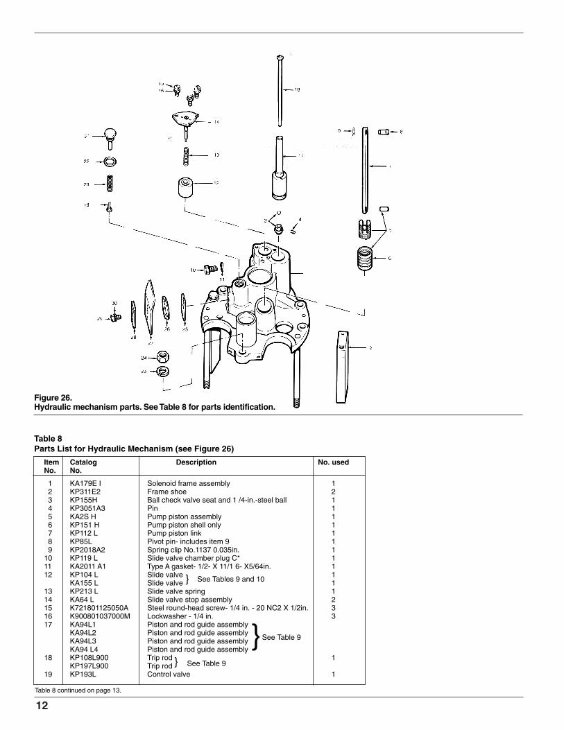
Table 8Parts List for Hydraulic Mechanism (see Figure 26)
Item Catalog Description No. usedNo. No.
1 KA179E I Solenoid frame assembly 12 KP311E2 Frame shoe 23 KP155H Ball check valve seat and 1 /4-in.-steel ball 14 KP3051A3 Pin 15 KA2S H Pump piston assembly 16 KP151 H Pump piston shell only 17 KP112 L Pump piston link 18 KP85L Pivot pin- includes item 9 19 KP2018A2 Spring clip No.1137 0.035in. 1
10 KP119 L Slide valve chamber plug C* 111 KA2011 A1 Type A gasket- 1/2- X 11/1 6- X5/64in. 112 KP104 L Slide valve 1
KA155 L Slide valve 113 KP213 L Slide valve spring 114 KA64 L Slide valve stop assembly 215 K721801125050A Steel round-head screw- 1/4 in. - 20 NC2 X 1/2in. 316 K900801037000M Lockwasher - 1/4 in. 317 KA94L1 Piston and rod guide assembly
KA94L2 Piston and rod guide assembly KA94L3 Piston and rod guide assembly KA94 L4 Piston and rod guide assembly
18 KP108L900 Trip rod 1KP197L900 Trip rod
19 KP193L Control valve 1
Table 8 continued on page 13.
Figure 26.Hydraulic mechanism parts. See Table 8 for parts identification.
}
}
See Tables 9 and 10
} See Table 9
See Table 9

13
Table 9.Part Numbers Used for Various Operating Sequences (above serial no. 52000)
Table 8. (continued)
S280-25-5
*Used only on solenoid frame assembly KA179E3
20 KP113L Control valve spring 121 KP118L Control valve stop screw 122 KP3013A12 Steel lockwasher- 1/2 in. X 0.170 in. X .099 in. 123 K900801043000A Steel lockwasher - 7/16 in. X 0.156 in. X 0.109 in. 124 K880201114043A Hexhead steel nut- 7/16 in. - 14NC2 125 KP222L Operations selector gasket 126 KP123L Plate selector. standard 127 KP315E Dielectric shield 128 KP223L Plate. clamping 129 K730101131050A Steel hex cap screw - 5/16 in. - 18NC2 X 1/2 in. 130 K900801031000D Lockwasher- 5/16in X 0.125in. X 0.78in 1
*Same catalog no. as above**Not used in this sequence.
***Slide-valve spring omitted. All others use KP213L slide-valve spring.†Uses KP226L control valve plate. All others use KP123L.
††Uses KA123L control valve plate. All others have none.Note: In order to have all fast-trip operations, a solenoid frame assembly must be ordered.
Trip Trip Slide Spring, StopCurve. Timing Piston Rod Valve Slide Valve Slide Valve Spacer
3 delayed KA94L-1 KP108L900 KP104L KP213L KA64L KP332HA 4 delayed * * * * * * *B 4 delayed*** * * KA155L * KPl105L& KP106L **B 3 delayed* * * * * * * * KP233LB 2 delayed * * KP104L * KA64L KP332HB 3 fast, 1 delayed KA94L-3 * * * * **B 2 fast, 2 delayed KA94L-1 * * * * **B 2 fast, 1 delayed KA94L-4 * * * * **B 1 fast, 3 delayed KA94L-2 KP197L900 * * * **B 1 fast, 2 delayed KA94L-1 KP108L900 * * * KP233LB 1 fast, 1 delayed KA94L-4 * * * * *C 4 delayed*** KA94L-1 * KAl155L * KP105L & KP106L **C 3 delayed* * * * * * * * KP233LC 2 delayed * * KP104L * KA64L KP332HC 2 fast, 2 delayed * * * * * * *C 2 fast, 1 delayed KA94L-4 * * * * **C 1 fast, 3 delayed KA94L-2 KP197L900 * * * **C 1 fast, 2 delayed KA94L-1 KP1108L900 * * * KP233LC 1 fast, 1 delayed KA94L-4 * * * * *D 4 delayed*** KA94L-1 * KA155L * KP105L & KP106L **D 3 delayed* * * * * * * * KP233LD 2 delayed * * KP104L * KA64L KP332HD 2 fast, 2 delayed * * KP104L * * **D 2 fast, 1 delayed KA94L4 * * * * **D 1 fast, 3 delayed KA94L-2 KP197L900 * * * **D 1 fast, 2 delayed KA94L-1 KP108L900 * * * KP233LD 1 fast, 1 delayed KA94L-4 * * * * *E 2 fast, 2 delayed” KA94L-1 * * KP194L * **E 1 fast. 3 delayed” KA94L-2 * * * * **E 1 fast, 2 delayed” KA94L-1 * * * * *F 3 fast 1 delayedit KA94L-3 * * KP213L * **F 2 fast 2 delayed KA94L-1 * * * * **F 2 fast, 1 delayed KA94L-4 * * * * **F 1 fast, 3 delayed KA94L-2 KP197L900 * * * **F 1 fast, 2 delayed KA94L-1 KP108L900 * * * KP233L

14
Figure 27.Parts for most commonly usedsequence, two fast and two delayed.*Only on units with solenoid frameKA179E3.
Figure 28.Installation of special slide valve usedfor delayed-only operations. No slide-valve spring is used.
Figure 29.Special parts used for one fast and threedelayed sequence.
Figure 30.Location of spacer under trip piston.
ChangingTime-Current SettingsTime-current curves for the Type E reclos-er indicate minimum-trip and the interrupt-ing capacity range plotted to an averageclearing time for each opening of therecloser contacts. Recloser curves arelabeled to represent their relative speed ofopening with A being fast, B delayed, Cextra delayed, D steep delayed, E anintermediate delayed, and F a slightly lessdelayed curve than B curve. To provide alloperations on the A curve, a specialsolenoid frame assembly must be ordered( KA179E3). To select operations on theB, C, or D curves, merely loosen the cap-screw and clamping plate and reindex theorifice selector plate to the desireddelayed curve. For all operations on the Ecurve, the KP123L selector plate isremoved and a KP226L plate is insertedand indexed in its place. F curve opera-tion requires the removal of the fast shotblocking plug KP119L (on units with spe-cial solenoid frame assembly KA179E3)and the addition of a KA123L controlvalve. Selector plate setting for this Fcurve is indexed at B.
Changing Operating Sequence Specified combinations of hydraulic partsas in Table 9 permit the recloser to oper-ate along one curve(single timing) or witha combination of two curves (dual timing).When set for dual timing, the recloseroperates first on a fast curve and then ona slower curve. After a selected numberof operations, the recloser locks outFigures 27 to 30 illustrate the location ofthe various parts used for changing theoperating sequence to lockout.
Sequence AdjustmentsAfter any change or servicing of the hy-draulic mechanism, make sure to removeany air that may have been entrapped, byoperating the yellow control handle manu-ally seven or eight times. All changesshould also be verified with the testingprocedures that are explained in the“Periodic Inspection and Maintenance”section. It may also be necessary toadjust the hydraulic pump piston shell toenable pumping action to lockout in thefollowing manner.1. Lower the unit into the oil enough to
cover the hydraulic system. Operatethe recloser manually several times todispel any air in the hydraulic system.
2. Close the recloser, wait 4 minutes, andrapidly trip and close there closer threetimes. Then observe the position of thetrip rod. This rod should just be touch-ing the adjustable lockout level in thehead mechanism.
3. If the trip rod is not correctly posi-tioned, turn the pump piston shelI tocause it to pump more or less oil asrequired. Turning the shell off the bodytends to increase travel of the trip rod,whereas turning the shell into the bodydecreases trip-rod travel.

15
Figure 32.Bushing parts. See Table 10 for parts identification.
Figure 31.Lifting a bushing assembly.
S280-25-5
BushingsMaintenance of bushings is ordinarily lim-ited to an occasional cleaning. If, howev-er, a bushing is cracked or chipped,replace as follows:
NOTE: The recloser must be untanked toreplace the bushings.
DISASSEMBLY1. If not done previously, remove the lead
straps from bottom of each bushing byremoving nut, lockwasher, and flat-washer.
2. Remove the three bolts that secure thebushing clamps and lift the bushingsout of the head casting (Figure 31).
If further maintenance is to be performed,do not replace the bushings yet.
REASSEMBLY1. Position the new bushing gaskets on
the head mechanism.2. Place the bushing clamping gaskets
around the bushings.3. Carefully insert bushings into head
casting so that the flat part of the lowerterminal faces away from the center ofthe recloser mechanism.
4. Replace the bushing clamps and boltinto place.
5. Secure the lead straps to the bushingsby reinstalling the flatwasher, lock-washer and nut.
Table 10.Parts List for Bushings (see Figure 32)
Item Catalog Description No. usedNo. No.
1 KA160E23 Bushing assembly 22 KP2090A29 Bushing gasket, lower 23 KP121 L Bushing clamping gasket 24 K730115137200A Stainless steel hex cap screw - 3/8 in. - 16 NC2 X 6
2in.5 KP41 L Galvanized bushing clamp segment 66 KP3251A20 Bushing lead 17 KP2106A33 Tubing 18 KP3256A1 Bushing lead 19 KP2106A75 Tubing 1
10 K900525039087A 3/8 in. brass flatwasher 211 K900830037000A 3/8 in. bronze lockwasher 212 K880725321 037A 3/8 in. - 24UNF - 2 B brass hex nut 2

16
Figure 35.View of head mechanism.
Figure 33.Head operating mechanism.
Figure 34.Releasing plunger and contact rod.
Head MechanismDisassembly of the head mechanismshould rarely be required. Should thisbe necessary for any reason, followthese steps:1. Move operating lever to the OPEN
position.2. Figure 33 shows a head assembly
as it appears after the arc-inter-rupting structure, series-tripsolenoid, hydraulic mechanism,insulating stringers and bushingshave been removed. Removeself-locking nut and four hexcapscrews indicated in Figure 33.Note use of flat washer under capscrew nearest the operating lever.Also note that two pipe spacerswill be released.
3. Lift the operating mechanismassembly to expose the pivotpoint. Remove the C ring and pullout the pin. Lift out the entiremechanism.
4. Remove C ring (Figure34) and pullpin that secures the solenoidplunger to the operating mechanism.Then pull off spring clip and removepin that secures the contact rod. Thetrip rod is removed by removing theE-ring on the head casting side ofthe rod (Figure 20).
5. Figure 35 shows the head assem-bly as it appears after the operatingmechanism has been removed.Unhook lockout spring and oper-ating lever spring.
6. Remove sleet hood cover andcounter. Then drive out a pin (notshown) in the lockout lever.

17
Figure 26.Head mechanism parts being removed.
Figure 37.Driving out pins in counter shaft.
S280-25-5
7. Pull the operating lever and removemanual trip lever. Then lift out the lock-out cam and link assembly, and lock-out lever. See Figure 36.
8. Drive out the rollpin that secures thecounter lever assembly to the countershaft as illustrated in Figure 37. Pulloutthe shaft Note the flat washer that sep-arates the counter lever assembly anda post in the head casting.
9. Slip off the adjustable lockout lever(Figure 38).All major components have been re-
moved at this point, with the exception ofthe non-reclosing accessory. Descriptionof removal of this device is omittedbecause such procedure should never benecessary.

18
Figure 38.Lifting out adjustable trip lever.
Figure 39.Reassembling head mechanism.
Reassembly of the head mechanism can ingeneral be accomplished by reversing theforegoing procedure. Some helpful precau-tions are noted below.1. Install counter parts first.2. Next, position adjustable lockout lever
(Figure 38).3. Slide lockout spring lever, counter
spring, lockout cam and link assembly,and lockout lever onto their shaft. Notethat the hollow shaft end must pointtoward the sleet hood. Position thisassembly. Be sure to include the flat-washer on the end of the shaft. SeeFigure 39.
4. Now position the manual trip lever andinsert the operating lever. Pin the lock-out lever to the operating lever.
5. Connect the solenoid plunger and con-tact rod to the operating mechanism.Bolt the operating mechanism in theposition shown in Figure 33.

19
Figure 41.Parts for tank and liner. See Table 11 for parts identification.
Figure 40.Adjustable lockout lever setting.
S280-25-5
6. Connect adjustable lockout lever to theoperating mechanism by replacing theself-locking nut removed in the “HeadMechanism” section, Step 2.
7. Check adjustment of the lockout mech-anism as follows:A. Grasp the insulating tube portion of
the trip piston assembly (Figure23),and lift it until the trip piston contactsthe slide valve stop. Make a lightscribe mark on the insulating tube1/4 in. above the slide valve stop.
B.Release the trip piston tube andmove the operating lever to theCLOSED position.
C.Hold the operating lever with onehand to prevent the recloser fromopening out of oil. Then slowly raisethe insulating tube of the trip pistonassembly. Recloser should trip just asthe light mark made in step A moveseven with the top of the slide valvestop.
D.If tripping does not occur as describedin Step C, adjust self-locking nutsshown in Figure 40 to achieve correctoperation. Note that the mechanismcannot operate properly if the nuts aretight against the operating mechanismlever. Always back off either nut one-half turn before testing.
Table 11Parts List for Tank and Liner (see Figure 41)
Item Catalog Description No. usedNo. No.
1 KA145L2 Tank assembly 12 KP277E Tankwall insulation 13 KP191L Liner 14 K730101150350Q Electro zinc-plated steel hex cap screw- 4
1/2in.-13NC2 X3-1/4in.5 KP2028A23 Galvanized steel washer- 17/32- X 4
1-1/8-in. X1/8in.6 KP86 L Galvanized combination steel nut and pin 47 KA227H Ground clamp 2

Item Catalog Description No.No. No. used
27 KP2001 A2 Stainless steel groove pin- 3/32 in. X 1/2 in., Type 2 1
28 KA17L Lockout lever assembly 129 KP2001 A13 Stainless steel groove pin
-1/8 in.X1-1/4 in.,Type1 130 KP77L Operating shaft 131 KA5L Manual trip lever assembly, part of item 8
(KA92L) 132 KA72 L Trip lever assembly 133 KP3006A7 Spacer, counter shaft 134 KP33 L Operating mechanism frame spacer 235 KA37L Operating mechanism assembly 136 K730101143250A Steel hex cap screw
-7/16 in.-14NC2X2-1/2 in. 237 K900801043000A Steel lockwasher
- 7/16 in. - X 0.156in. X 0.109 in. 538 K730101143550A Steel hex cap screw
-7/16 in.-14NC2X5-1/2 in. 239 KA10L Insulating stringer, long 239A KP3149A33 Solenoid tie bolt 240 KA122 L Insulating stringer, short 141 K880201114043A Steel hex nut - 7/16 in. - 14 NC2 542 KP3125A4 Pivot pin 243 K970901312000M Retaining Ring 544 KA28L Solenoid plunger assembly 145 KP3007A162 Spacer 246 KA1 78 E Contact rod assembly 147 KP3125A1 Pivot pin 148 KP2018A1 Spring clip, no.1090 narrow, 0.041
dia. wire 149 K900201043000A Standard light steel flat washer
7/16 in. X59/64 in. X 0.080 in. 1(see Figure 35)*
20
Table 12Parts List for Head Assembly (Figure 42)
Figure 42.Parts for head assembly. See Table 12 for parts identification.
Item Catalog Description No.No. No. used
1 KP344L-2 Head Casting 12 KP282E900 Name plate and mounting screws 13 KP2119A13 Coil data plate, add continuous rating and
screws 14 KP1371R Operating data plate, add sequence and
screws 15 KP3106A12 Bushing in cover, counter shaft* 16 KP269L Bushing in cover, operating handle* 17 K970901500000 Open-type retaining ring* 18 KA92L Operating lever, includes shaft assembly
(KA5L) 19 KP258 L Counter shaft assembly 1
10 KA28C0IS Counter kit 111 K751501106062A Round-head self-tapping screw
No.4 X5/16in. 212 KP292 L Sleet hood cover plate 113 K781515112050A Steel round-head phillips self-tapping
screw— No.12 X1/2in. 414 KP764 H Lifting lug replacement kit 115 K900801050000Z Lockwasher 116 K730101150100C Standard hex capscrew
1/2in.- 13UNC2 X1 in. 117 KP2103-A4 O-ring head gasket 118 K900101051087C Flat washer- zinc plated 119 KP14L Lockout spring lever 120 KP158L Counter torsion spring 121 KA27L Lockout cam and link assembly 122 KP27H operating lever spring 123 KP99L Lockout spring 123A KP73L Lockout spring anchor pin 124 K721501125062C Zinc plated round head screw
-1/4in.-2OUNCA2AX5/8in. 125 K881001120025C Zinc plated hexnut-1/4in.-2OUNC2B 126 KA118L Counter lever assembly 1
*not shown
KDL7/05
1045 Hickory StreetPewaukee, WI 53072 USAwww.cooperpower.com
©2005 Cooper Power Systems or its affiliates.Kyle® is a registered trademark of Cooper Power Systems or its affiliates.


