Embed Size (px)
Citation preview

2 DVR 4120 Manual
SAFETY PRECAUTIONS
CAUTION
RISK OF ELECTRIC SHOCK DO NOT OPEN
WARNING: TO REDUCE THE RISK OF ELECTRICAL SHOCK,
DO NOT REMOVE COVER.
NO USER SERVICEABLE PARTS INSIDE.
REFER SERVICING TO QUALIFIED SERVICE PERSONAL.
The lightning flash with an arrowhead symbol within an equilateral triangle is
intended to alert the user to the presence of un-insulated “dangerous voltage”
within the product‟s enclosure that may be of sufficient magnitude to
constitute a risk of electric shock to persons.
The exclamation point within an equilateral triangle is intended to alert the
user to presence of important operating and maintenance (servicing)
instructions in the literature accompanying the appliance.
FCC COMPLIANCE NOTICE
THIS EQUIPMENT HAS BEEN TESTED AND FOUND TO COMPLY WITH THE LIMITS FOR A CLASS A DIGITAL
DEVICE, PURSUANT TO PART 15 OF THE FCC RULES. THESE LIMITS ARE DESIGNED TO PROVIDE
REASONABLE PROTECTION AGAINST HARMFUL INTERFERENCE WHEN THE EQUIPMENT IS OPERATED IN
A COMMERCIAL ENVIRONMENT. THIS EQUIPMENT GENERATES, USES, AND CAN RADIATE RADIO
FREQUENCY ENERGY AND IF NOT INSTALLED AND USED IN ACCORDANCE WITH THE INSTRUCTION
MANUAL, MAY CAUSE HARMFUL INTERFERENCE TO RADIO COMMUNICATIONS. OPERATION OF THIS
EQUIPMENT IN A RESIDENTIAL AREA IS LIKELY TO CAUSE HARMFUL INTERFERENCE, IN WHICH CASE
USERS WILL BE REQUIRED TO CORRECT THE INTERFERENCE AT THEIR OWN EXPENSE.
WARNING: CHANGES OR MODIFICATIONS NOT EXPRESSLY APPROVED BY THE PARTY RESPONSIBLE FOR
COMPLIANCE COULD VOID THE USER‟S AUTHORITY TO OPERATE THE EQUIPMENT.
THIS CLASS OF DIGITAL APPARATUS MEETS ALL REQUIREMENTS OF THE CANADIAN INTERFERENCE-
CAUSING EQUIPMENT REGULATIONS.
DVR 4120 Manual 3
This manual is a setup and maintenance guide that can be used for reference when setting up
the unit and for troubleshooting when a problem occurs. Only authorized personnel should
attempt to repair this unit.
Manufactory reserves the right to make changes to the product represented by this manual
without notice.
The following text, symbol marks and special messages throughout this guide:
WARNING
Text set off in this manner indicates that failure to follow directions could result in
bodily harm or loss of life.
CAUTION
Text set off in this manner indicates that failure to follow directions could result in
damage to equipment or loss of information.
NOTICE
Text set off in this manner indicates topics of interests that can help the user
understand the product better.
Convention used in this manual

4 DVR 4120 Manual
① INTRO
Convention used in this manual 3
Introduction 7
Contents 8
Front Panel 9
Rear Panel 10
Remote Controller 11
② OPERATION
OSD 13
Display 15
Sequence 16
Privacy / Mute / Audio 17
Recording 18
Normal Search 20
Statistics Search 22
Smart Search 23
Event Search 24
Backup 25
PTZ 26
Alarm 30
Set Alarm 31
Motion Alarm 32
③ REMOTE VIEWER
Installation 35
Connection 36
Setup 37
Status / Audio / PTZ 38
Sequence / Display 39
Search / Backup 40
④ SETUP
Login 44
Menu 45
Recording Schedule 46
Camera Registration 48
Audio 50
HDD 51
Pre-post Recording 53
Network Connection 54
Service Port & DDNS 56
Update Server 57
Adjustment 58
OSD 59
Sequence 60
Spot 61
Information & Update 62
TABLE OF CONTENTS
DVR 4120 Manual 5
Date / Time 64
System Log 65
Shutdown 66
Password 67
Parameter 68
PTZ & RS-485 69
Event 71
Alarm Input 73
Motion Alarm Output 74
Remote Controller 75
Etc. 76
⑤ APPENDIX
Specifications 78
Troubleshooting 80
Tech Support Code 82
⑥ MEMO
TABLE OF CONTENTS
NOTICE
The specification or design of product is subject to change without notice.
6 DVR 4120 Manual
DVR 4120 Manual 7
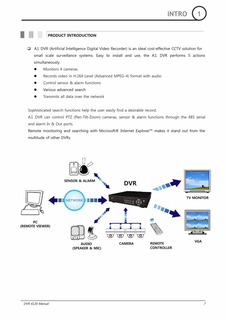
A.I. DVR (Artificial Intelligence Digital Video Recorder) is an ideal cost-effective CCTV solution for
small scale surveillance systems. Easy to install and use, the A.I. DVR performs 5 actions
simultaneously.
Monitors 4 cameras
Records video in H.264 Level (Advanced MPEG-4) format with audio
Control sensor & alarm functions
Various advanced search
Transmits all data over the network
Sophisticated search functions help the user easily find a desirable record.
A.I. DVR can control PTZ (Pan-Tilt-Zoom) cameras, sensor & alarm functions through the 485 serial
and alarm In & Out ports.
Remote monitoring and searching with Microsoft® Internet Explorer™ makes it stand out from the
multitude of other DVRs.
PRODUCT INTRODUCTION
INTRO 1
SENSOR & ALARM
PC
AUDIO
TV MONITOR
CAMERA REMOTE
NETWORK
VGA
DVR
(SPEAKER & MIC) CONTROLLER
(REMOTE VIEWER)
8 DVR 4120 Manual
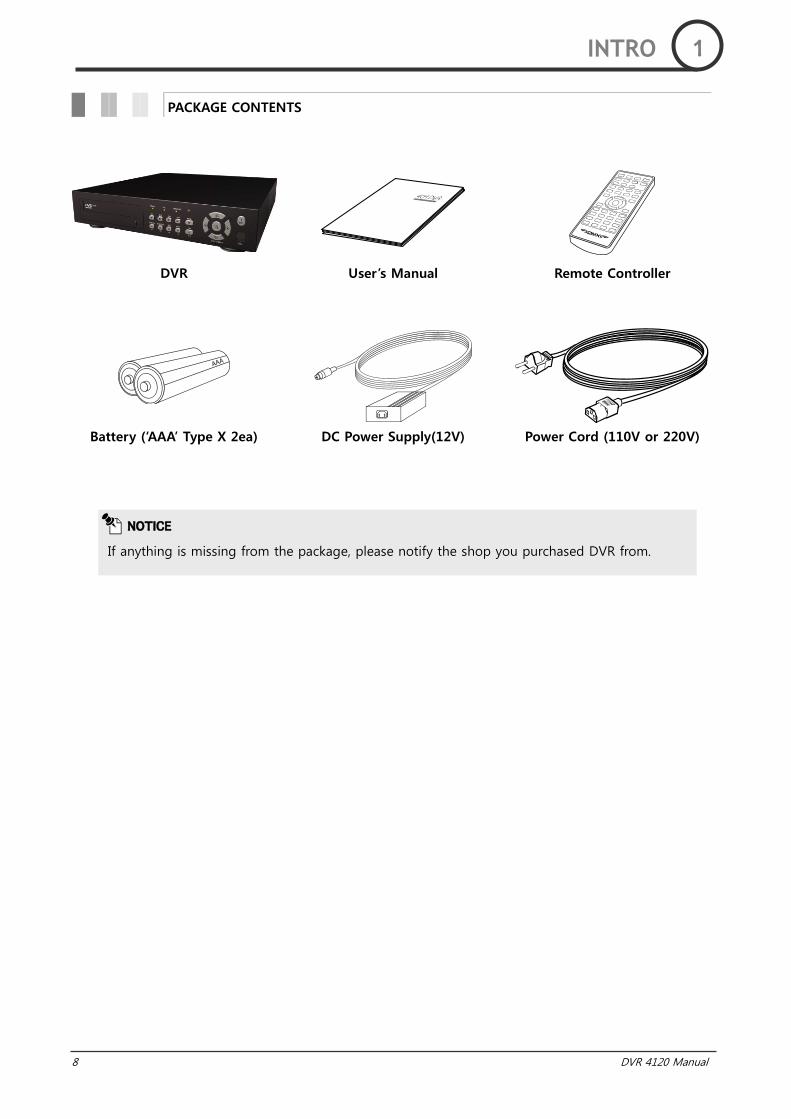
DVR User‟s Manual Remote Controller
Battery („AAA‟ Type X 2ea) DC Power Supply(12V) Power Cord (110V or 220V)
PACKAGE CONTENTS
NOTICE
If anything is missing from the package, please notify the shop you purchased DVR from.
INTRO 1
DVR 4120 Manual 9
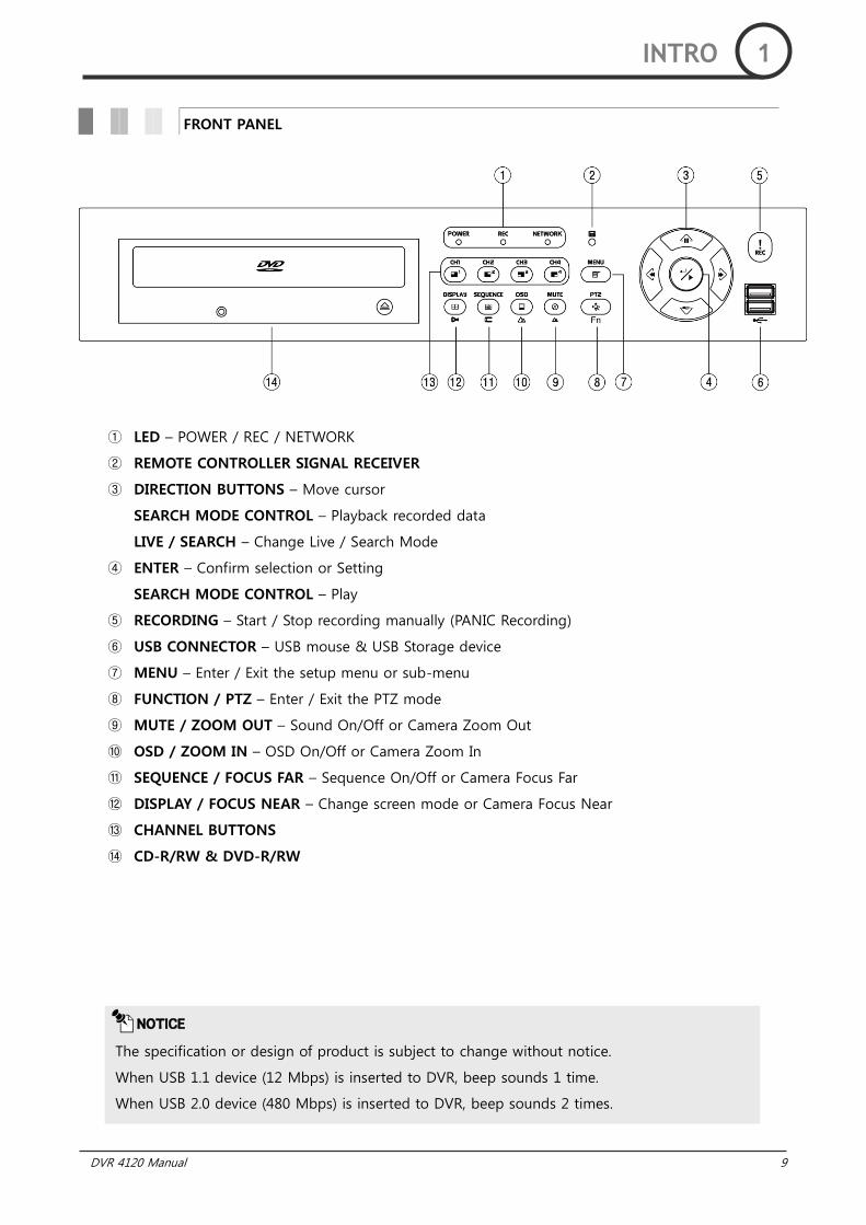
① LED – POWER / REC / NETWORK
② REMOTE CONTROLLER SIGNAL RECEIVER
③ DIRECTION BUTTONS – Move cursor
SEARCH MODE CONTROL – Playback recorded data
LIVE / SEARCH – Change Live / Search Mode
④ ENTER – Confirm selection or Setting
SEARCH MODE CONTROL – Play
⑤ RECORDING – Start / Stop recording manually (PANIC Recording)
⑥ USB CONNECTOR – USB mouse & USB Storage device
⑦ MENU – Enter / Exit the setup menu or sub-menu
⑧ FUNCTION / PTZ – Enter / Exit the PTZ mode
⑨ MUTE / ZOOM OUT – Sound On/Off or Camera Zoom Out
⑩ OSD / ZOOM IN – OSD On/Off or Camera Zoom In
⑪ SEQUENCE / FOCUS FAR – Sequence On/Off or Camera Focus Far
⑫ DISPLAY / FOCUS NEAR – Change screen mode or Camera Focus Near
⑬ CHANNEL BUTTONS
⑭ CD-R/RW & DVD-R/RW
FRONT PANEL
NOTICE
The specification or design of product is subject to change without notice.
When USB 1.1 device (12 Mbps) is inserted to DVR, beep sounds 1 time.
When USB 2.0 device (480 Mbps) is inserted to DVR, beep sounds 2 times.
INTRO 1
10 DVR 4120 Manual
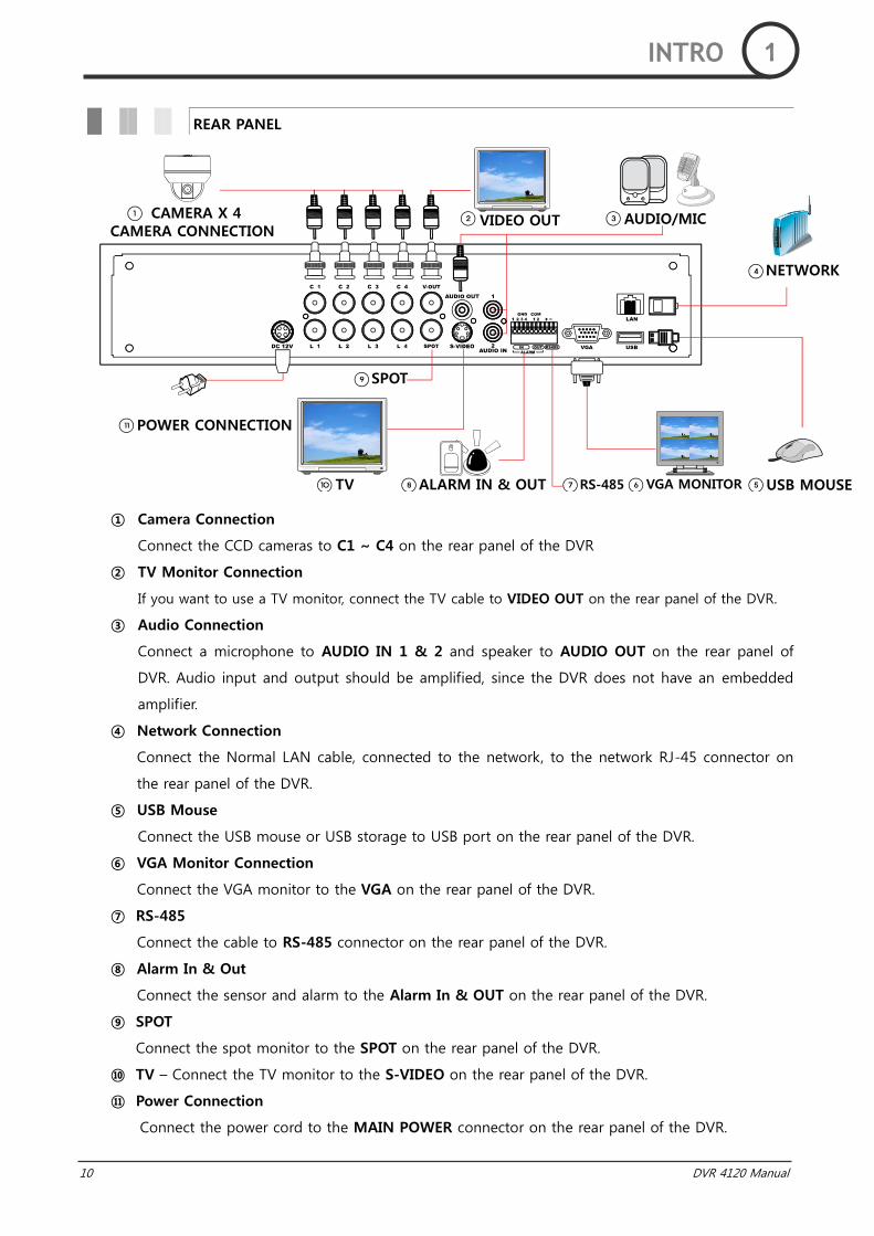
REAR PANEL
① Camera Connection
Connect the CCD cameras to C1 ~ C4 on the rear panel of the DVR
② TV Monitor Connection
If you want to use a TV monitor, connect the TV cable to VIDEO OUT on the rear panel of the DVR.
③ Audio Connection
Connect a microphone to AUDIO IN 1 & 2 and speaker to AUDIO OUT on the rear panel of
DVR. Audio input and output should be amplified, since the DVR does not have an embedded
amplifier.
④ Network Connection
Connect the Normal LAN cable, connected to the network, to the network RJ-45 connector on
the rear panel of the DVR.
⑤ USB Mouse
Connect the USB mouse or USB storage to USB port on the rear panel of the DVR.
⑥ VGA Monitor Connection
Connect the VGA monitor to the VGA on the rear panel of the DVR.
⑦ RS-485
Connect the cable to RS-485 connector on the rear panel of the DVR.
⑧ Alarm In & Out
Connect the sensor and alarm to the Alarm In & OUT on the rear panel of the DVR.
⑨ SPOT
Connect the spot monitor to the SPOT on the rear panel of the DVR.
⑩ TV – Connect the TV monitor to the S-VIDEO on the rear panel of the DVR.
⑪ Power Connection
Connect the power cord to the MAIN POWER connector on the rear panel of the DVR.
CAMERA X 4
POWER CONNECTION
CAMERA CONNECTION VIDEO OUT AUDIO/MIC
NETWORK
USB MOUSE VGA MONITOR RS-485 ALARM IN & OUT TV
SPOT
INTRO 1
DVR 4120 Manual 11
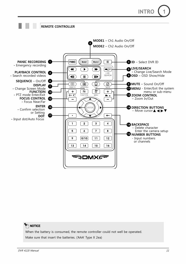
REMOTE CONTROLLER
NOTICE
When the battery is consumed, the remote controller could not well be operated.
Make sure that insert the batteries. („AAA‟ Type X 2ea)
INTRO 1
MODE1 – Ch1 Audio On/Off
MODE2 – Ch2 Audio On/Off
ZOOM CONTROL
DOT
- Focus Near/Far
PANIC RECORDING - Emergency recording
PLAYBACK CONTROL - Search recorded videos
SEQUENCE – On/Off
DISPLAY - Change Screen Mode
FUNCTION - PTZ mode Enter/Exit
FOCUS CONTROL
ENTER - Confirm selection
or Setting
ID – Select DVR ID
LIVE/SEARCH - Change Live/Search Mode OSD – OSD Show/Hide
MUTE – Sound On/Off
MENU - Enter/Exit the system menu or sub-menu
– Zoom In/Out
– Move cursor DIRECTION BUTTONS
BACKSPACE – Delete character
Enter the camera setup NUMBER BUTTONS - Input numbers or channels
- Input dot/Auto Focus
12 DVR 4120 Manual
DVR 4120 Manual 13
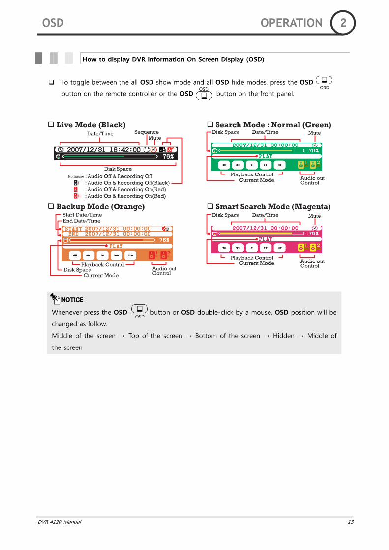
To toggle between the all OSD show mode and all OSD hide modes, press the OSD
button on the remote controller or the OSD button on the front panel.
How to display DVR information On Screen Display (OSD)
NOTICE
Whenever press the OSD button or OSD double-click by a mouse, OSD position will be
changed as follow.
Middle of the screen → Top of the screen → Bottom of the screen → Hidden → Middle of
the screen
OSD
OSD OSD
OSD OPERATION 2
14 DVR 4120 Manual
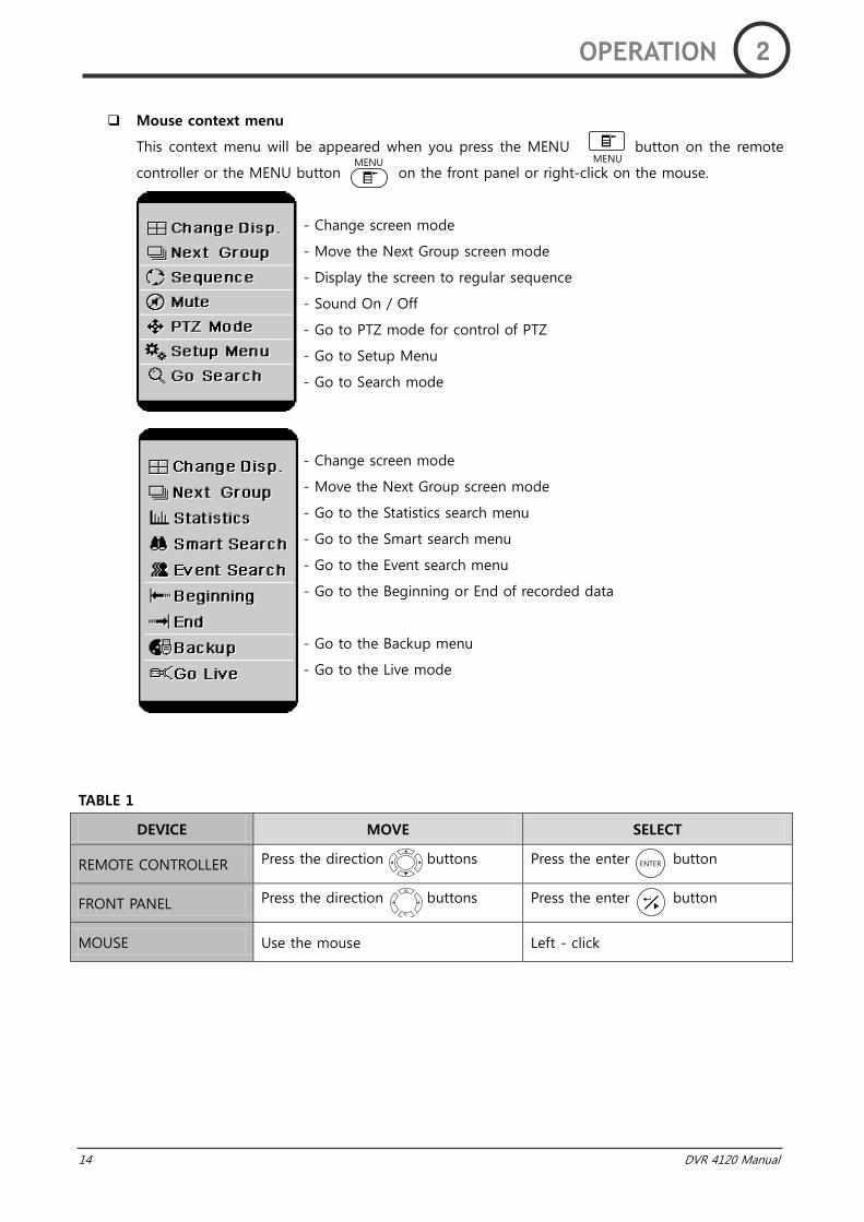
Mouse context menu
This context menu will be appeared when you press the MENU button on the remote
controller or the MENU button on the front panel or right-click on the mouse.
- Change screen mode
- Move the Next Group screen mode
- Display the screen to regular sequence
- Sound On / Off
- Go to PTZ mode for control of PTZ
- Go to Setup Menu
- Go to Search mode
- Change screen mode
- Move the Next Group screen mode
- Go to the Statistics search menu
- Go to the Smart search menu
- Go to the Event search menu
- Go to the Beginning or End of recorded data
- Go to the Backup menu
- Go to the Live mode
TABLE 1
DEVICE MOVE SELECT
REMOTE CONTROLLER Press the direction buttons Press the enter button
FRONT PANEL Press the direction buttons Press the enter button
MOUSE Use the mouse Left - click
MENU MENU
ENTER
OPERATION 2
DVR 4120 Manual 15
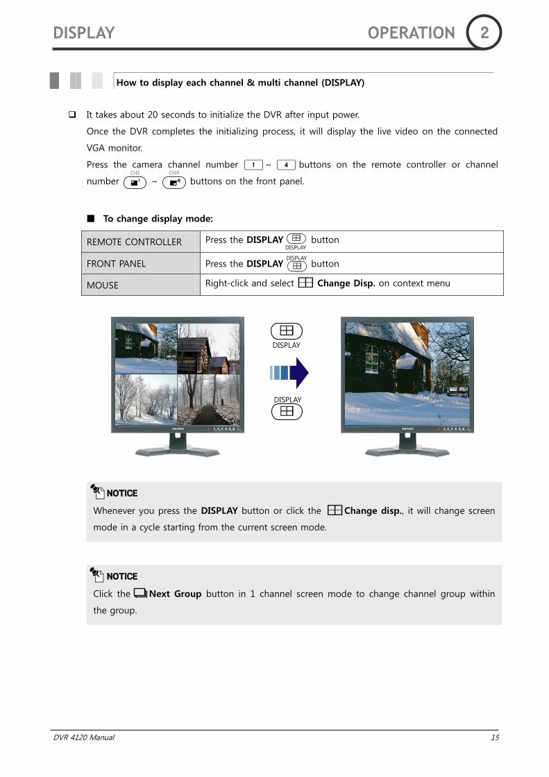
It takes about 20 seconds to initialize the DVR after input power.
Once the DVR completes the initializing process, it will display the live video on the connected
VGA monitor.
Press the camera channel number ~ buttons on the remote controller or channel
number ~ buttons on the front panel.
To change display mode:
REMOTE CONTROLLER Press the DISPLAY button
FRONT PANEL Press the DISPLAY button
MOUSE Right-click and select Change Disp. on context menu
How to display each channel & multi channel (DISPLAY)
NOTICE
Click the Next Group button in 1 channel screen mode to change channel group within
the group.
NOTICE
Whenever you press the DISPLAY button or click the Change disp., it will change screen
mode in a cycle starting from the current screen mode.
DISPLAY
DISPLAY
DISPLAY
DISPLAY OPERATION 2
DISPLAY

16 DVR 4120 Manual
In the sequence mode, each channel is displayed on the screen for the preset period of time.
To enable / disable sequence mode:
REMOTE CONTROLLER Press the SEQUENCE button
FRONT PANEL Press the SEQUENCE button
MOUSE Right-click and select Sequence in context menu in Live mode
How to rotate monitoring channels (SEQUENCE)
NOTICE
When sequence mode is „On‟, icon will be appeared on OSD.
SEQUENCE OPERATION 2
SEQUENCE
SEQUENCE
DVR 4120 Manual 17
Go to SETUP menu (1.BASIC SETTING – 2.CAMERA REGISTRATION) to do setting the private
protection.
STEP 1 Press the MENU button and then press + button on the remote
controller.
STEP 2 Select „On‟ in a privacy tab of the channel which you want to set up.
STEP 3 Monitoring channels will not be shown on the screen. But the video can be
recorded and played in the search mode.
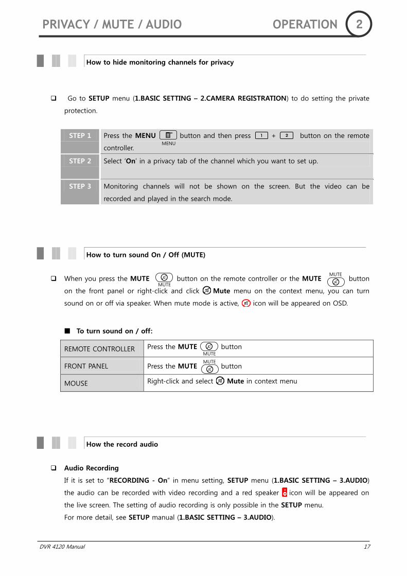
When you press the MUTE button on the remote controller or the MUTE button
on the front panel or right-click and click Mute menu on the context menu, you can turn
sound on or off via speaker. When mute mode is active, icon will be appeared on OSD.
To turn sound on / off:
REMOTE CONTROLLER Press the MUTE button
FRONT PANEL Press the MUTE button
MOUSE Right-click and select Mute in context menu
Audio Recording
If it is set to “RECORDING - On” in menu setting, SETUP menu (1.BASIC SETTING – 3.AUDIO)
the audio can be recorded with video recording and a red speaker icon will be appeared on
the live screen. The setting of audio recording is only possible in the SETUP menu.
For more detail, see SETUP manual (1.BASIC SETTING – 3.AUDIO).
How to hide monitoring channels for privacy
How to turn sound On / Off (MUTE)
How the record audio
PRIVACY / MUTE / AUDIO OPERATION 2
MENU
MUTE
MUTE
MUTE
MUTE
18 DVR 4120 Manual
All channels are recorded automatically when you use DVR at first time. If you want to change
the recording schedule, you can change it in the SETUP menu (1.BASIC SETTING –
1.RECORDING SCHEDULE).
There are four ways for recording; Schedule recording, PANIC recording, Motion Event recording
and Alarm Input recording. (6. TECHNICAL SETTING – 3.ALARM INPUT)
Schedule Recording
You can select that the recording channel, day, time, image quality, REC mode, resolution and
number of frame for recording. For more detail, see SETUP manual (1.BASIC SETTING –
1.RECORDING SCHEDULE).
PANIC (EMERGENCY RECORDING)
When an emergency situation occurs, by pressing the PANIC button on the remote
controller or REC button on the front panel, you can record pre - recorded image and
the video on all cameras regardless of recording schedule manually.
To start or stop panic recording manually:
REMOTE CONTROLLER Press the PANIC button
FRONT PANEL Press the REC button
How to record monitoring channels
NOTICE
On time lapse recording mode, (Blue) icon displayed on channel.
On all event (motion, alarm input) recording mode, (Cyan) icon displayed on channel.
On panic recording mode, (Red) icon displayed on each channel and icon is flicker on
screen. Panic recording cannot be controlled with a mouse.
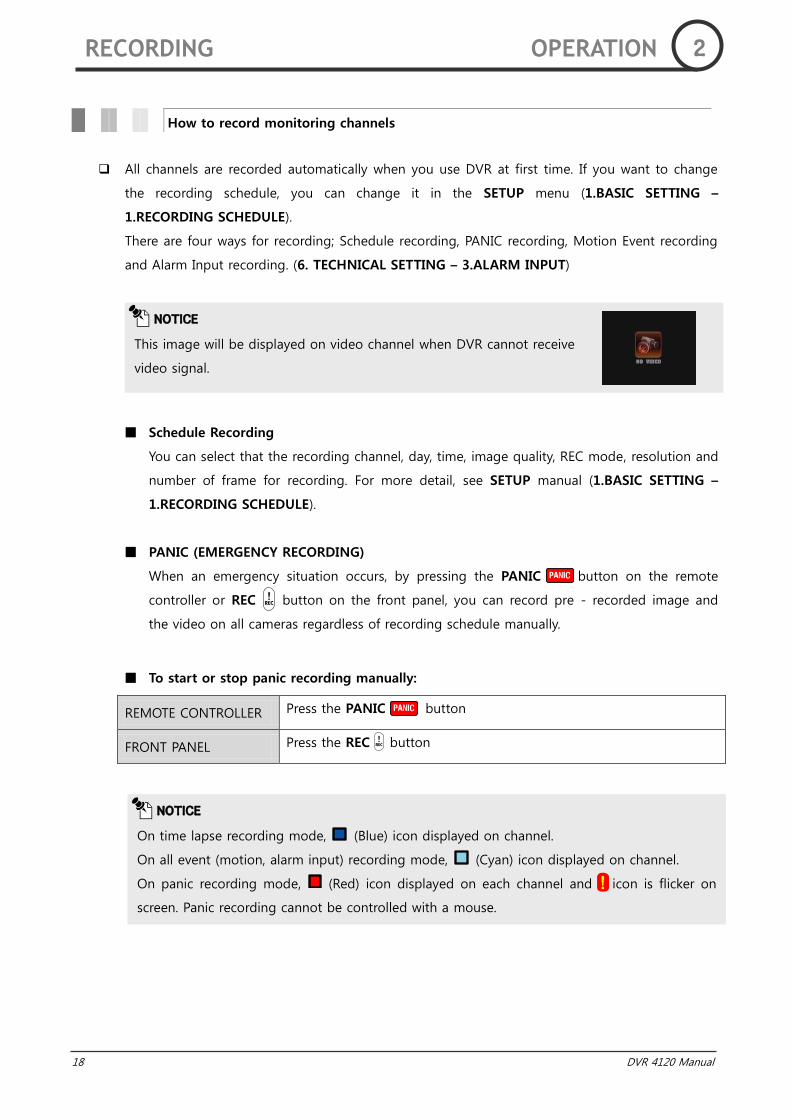
NOTICE
This image will be displayed on video channel when DVR cannot receive
video signal.
RECORDING OPERATION 2
DVR 4120 Manual 19
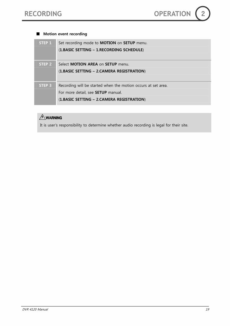
Motion event recording
STEP 1 Set recording mode to MOTION on SETUP menu.
(1.BASIC SETTING – 1.RECORDING SCHEDULE)
STEP 2 Select MOTION AREA on SETUP menu.
(1.BASIC SETTING – 2.CAMERA REGISTRATION)
STEP 3 Recording will be started when the motion occurs at set area.
For more detail, see SETUP manual.
(1.BASIC SETTING – 2.CAMERA REGISTRATION)
WARNING
It is user‟s responsibility to determine whether audio recording is legal for their site.
RECORDING OPERATION 2
20 DVR 4120 Manual
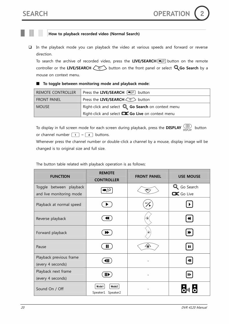
In the playback mode you can playback the video at various speeds and forward or reverse
direction.
To search the archive of recorded video, press the LIVE/SEARCH button on the remote
controller or the LIVE/SEARCH button on the front panel or select Go Search by a
mouse on context menu.
To toggle between monitoring mode and playback mode:
REMOTE CONTROLLER Press the LIVE/SEARCH button
FRONT PANEL Press the LIVE/SEARCH button
MOUSE Right-click and select Go Search on context menu
Right-click and select Go Live on context menu
To display in full screen mode for each screen during playback, press the DISPLAY button
or channel number ~ buttons.
Whenever press the channel number or double-click a channel by a mouse, display image will be
changed is to original size and full size.
The button table related with playback operation is as follows:
FUNCTION REMOTE
CONTROLLER FRONT PANEL USE MOUSE
Toggle between playback
and live monitoring mode
Go Search
Go Live
Playback at normal speed
Reverse playback
Forward playback
Pause
Playback previous frame
(every 4 seconds) -
Playback next frame
(every 4 seconds) -
Sound On / Off
-
How to playback recorded video (Normal Search)
SEARCH OPERATION 2
DISPLAY
Speaker1 Speaker2
DVR 4120 Manual 21
NOTICE
This image will be displayed on video channel when DVR does not have
recorded video data.
NOTICE
Whenever you press the reverse and forward button, the playback speed will be faster.
(3 steps)
SEARCH OPERATION 2
22 DVR 4120 Manual
There are three ways in advanced search: STATISTICS SEARCH, SMART SEARCH, and EVENT
SEARCH.
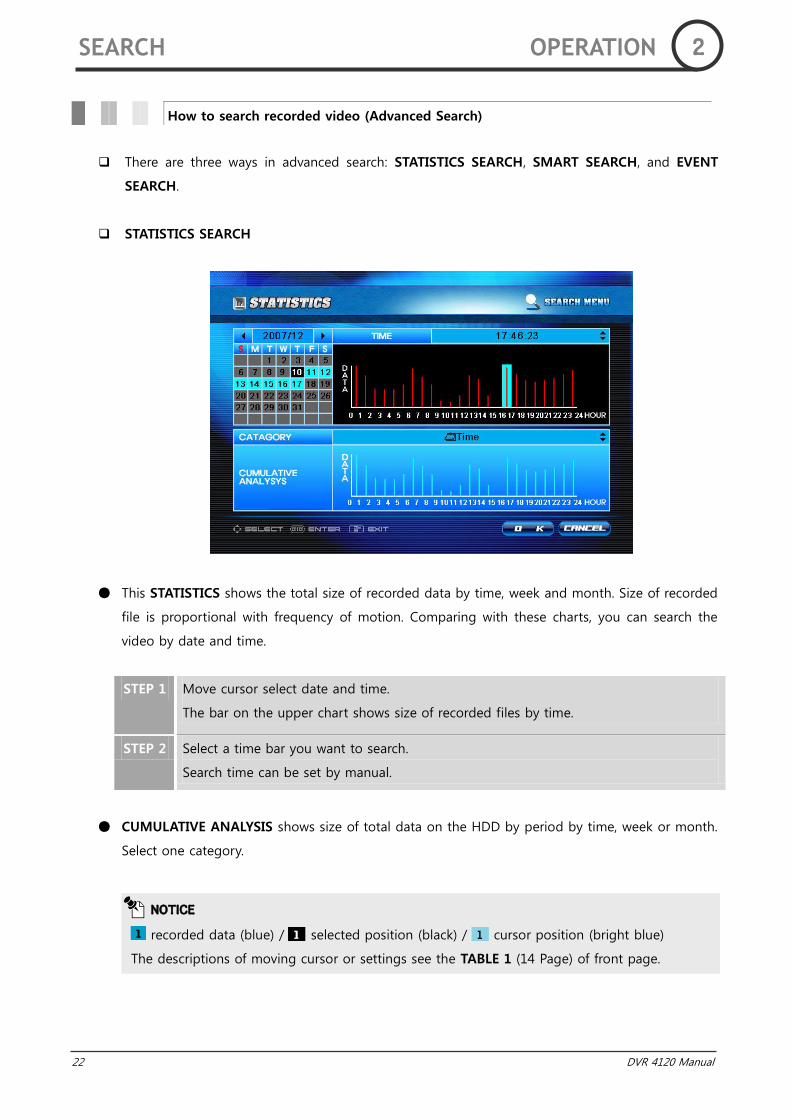
STATISTICS SEARCH
This STATISTICS shows the total size of recorded data by time, week and month. Size of recorded
file is proportional with frequency of motion. Comparing with these charts, you can search the
video by date and time.
STEP 1 Move cursor select date and time.
The bar on the upper chart shows size of recorded files by time.
STEP 2 Select a time bar you want to search.
Search time can be set by manual.
CUMULATIVE ANALYSIS shows size of total data on the HDD by period by time, week or month.
Select one category.
How to search recorded video (Advanced Search)
NOTICE
recorded data (blue) / selected position (black) / cursor position (bright blue)
The descriptions of moving cursor or settings see the TABLE 1 (14 Page) of front page.
SEARCH OPERATION 2
DVR 4120 Manual 23
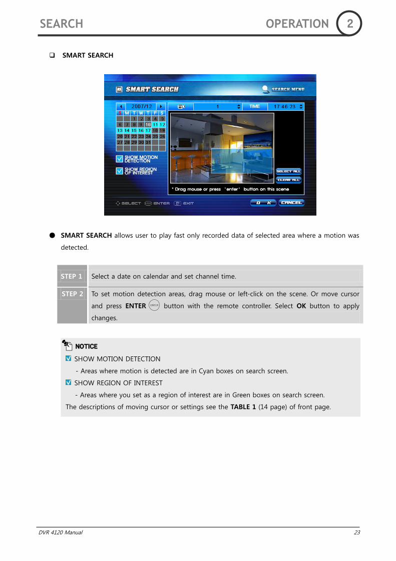
SMART SEARCH
SMART SEARCH allows user to play fast only recorded data of selected area where a motion was
detected.
STEP 1 Select a date on calendar and set channel time.
STEP 2 To set motion detection areas, drag mouse or left-click on the scene. Or move cursor
and press ENTER button with the remote controller. Select OK button to apply
changes.
NOTICE
SHOW MOTION DETECTION
- Areas where motion is detected are in Cyan boxes on search screen.
SHOW REGION OF INTEREST
- Areas where you set as a region of interest are in Green boxes on search screen.
The descriptions of moving cursor or settings see the TABLE 1 (14 page) of front page.
SEARCH OPERATION 2
24 DVR 4120 Manual
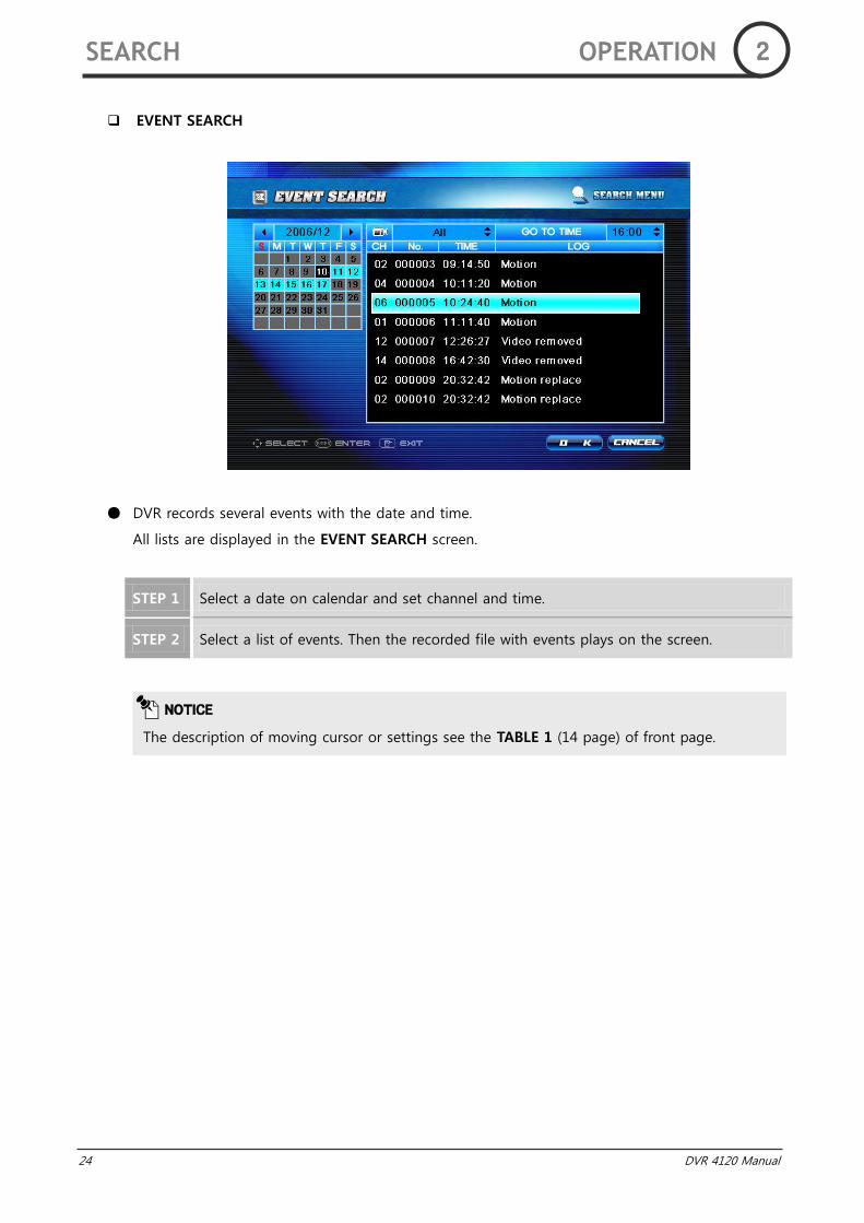
EVENT SEARCH
DVR records several events with the date and time.
All lists are displayed in the EVENT SEARCH screen.
STEP 1 Select a date on calendar and set channel and time.
STEP 2 Select a list of events. Then the recorded file with events plays on the screen.
NOTICE
The description of moving cursor or settings see the TABLE 1 (14 page) of front page.
SEARCH OPERATION 2
DVR 4120 Manual 25
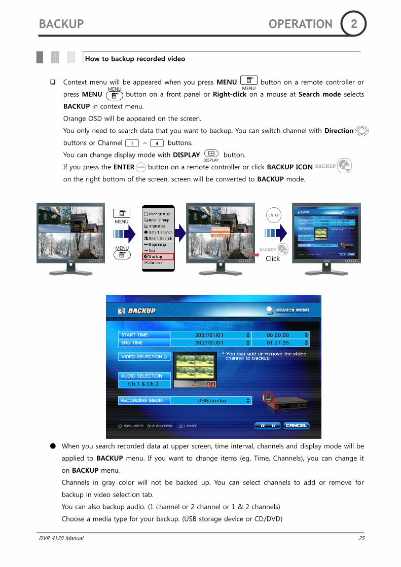
Context menu will be appeared when you press MENU button on a remote controller or
press MENU button on a front panel or Right-click on a mouse at Search mode selects
BACKUP in context menu.
Orange OSD will be appeared on the screen.
You only need to search data that you want to backup. You can switch channel with Direction
buttons or Channel ~ buttons.
You can change display mode with DISPLAY button.
If you press the ENTER button on a remote controller or click BACKUP ICON
on the right bottom of the screen, screen will be converted to BACKUP mode.
When you search recorded data at upper screen, time interval, channels and display mode will be
applied to BACKUP menu. If you want to change items (eg. Time, Channels), you can change it
on BACKUP menu.
Channels in gray color will not be backed up. You can select channels to add or remove for
backup in video selection tab.
You can also backup audio. (1 channel or 2 channel or 1 & 2 channels)
Choose a media type for your backup. (USB storage device or CD/DVD)
How to backup recorded video
BACKUP OPERATION 2
MENU MENU
DISPLAY
MENU
MENU
Click
26 DVR 4120 Manual
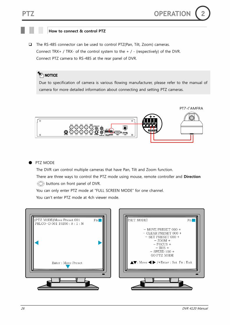
The RS-485 connector can be used to control PTZ(Pan, Tilt, Zoom) cameras.
Connect TRX+ / TRX- of the control system to the + / - (respectively) of the DVR.
Connect PTZ camera to RS-485 at the rear panel of DVR.
PTZ MODE
The DVR can control multiple cameras that have Pan, Tilt and Zoom function.
There are three ways to control the PTZ mode using mouse, remote controller and Direction
buttons on front panel of DVR.
You can only enter PTZ mode at “FULL SCREEN MODE” for one channel.
You can‟t enter PTZ mode at 4ch viewer mode.
How to connect & control PTZ
NOTICE
Due to specification of camera is various flowing manufacturer, please refer to the manual of
camera for more detailed information about connecting and setting PTZ cameras.
PTZ OPERATION 2
PTZ-CAMERA
DVR 4120 Manual 27
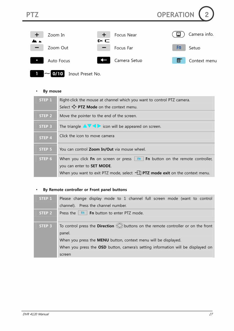
• By mouse
STEP 1 Right-click the mouse at channel which you want to control PTZ camera.
Select PTZ Mode on the context menu.
STEP 2 Move the pointer to the end of the screen.
STEP 3 The triangle icon will be appeared on screen.
STEP 4 Click the icon to move camera
STEP 5 You can control Zoom In/Out via mouse wheel.
STEP 6 When you click Fn on screen or press Fn button on the remote controller,
you can enter to SET MODE.
When you want to exit PTZ mode, select PTZ mode exit on the context menu.
• By Remote controller or Front panel buttons
STEP 1 Please change display mode to 1 channel full screen mode (want to control
channel). Press the channel number.
STEP 2 Press the Fn button to enter PTZ mode.
STEP 3 To control press the Direction buttons on the remote controller or on the front
panel.
When you press the MENU button, context menu will be displayed.
When you press the OSD button, camera‟s setting information will be displayed on
screen
PTZ OPERATION 2
Focus Far
Zoom In
Zoom Out
Auto Focus
Focus Near
Input Preset No.
Camera Setup
Camera info.
Setup
Context menu
28 DVR 4120 Manual
SET MODE
During PTZ mode, you can enter the SET MODE using Fn button. You can set up PTZ
cameras and Pre-set positions at the SET MODE.
To enter SET MODE, please press Fn button on remote controller or front panel or click
the Fn icon on the screen.
• MOVE PRESET
You can move the camera to the Pre-set position at this menu. You can choose the Pre-set
number using ←, →button on the remote controller, ←, → button on the front panel or -,+
icon on the screen. To move the camera, please press the enter button or click MOVE PRESET
icon on the screen.
• CLEAR PRESET
You can delete the pre-set positions at this menu. You can choose the Pre-set number using
←, → button on the remote controller, ←, → button on the front panel or -, + icon on the
screen. To delete the Pre-set position, please press the enter button or click CLEAR PRESET
icon on the screen.
• SET PRESET
You can set the Pre-set position at this menu. You can set the number 1~255 (max 255
numbers).
You can choose the Pre-set number using ←, → button on the remote controller, ←, →
button on the front panel or -, + icon on the screen. To set the Pre-set position, please press
the enter button or click SET PRESET icon on the screen.
• ZOOM
You can adjust the magnification at this menu. You can adjust the magnification using ←, →
button on the remote controller, ←, → button on the front panel or –, + icon on the screen.
– icon corresponds to Zoom Out. + icon corresponds to Zoom In. About the available range
of magnification, please refer to the manual of the camera that you have set.
• FOCUS
You can adjust the Focus at this menu. You can adjust the Focus using ←, → button on the
remote controller, ←, → button on the front panel or –, + icon on the screen. – icon
corresponds to Far. + icon corresponds to Near.
NOTICE
To use MOVE PRESET and CLEAR PRESET function, you must set one pre-set position at least
at SET PRESET mode.
PTZ OPERATION 2
DVR 4120 Manual 29
• IRIS
You can control the IRIS of camera at this menu. Please adjust light inflow using Opening IRIS
or Closing IRIS. You can adjust the IRIS by ←, → button on the remote controller, ←, →
button on the front panel or –, + icon on the screen. – icon corresponds to closing the IRIS.
+ icon corresponds to opening the IRIS.
• SPEED
You can adjust Speed of the PTZ camera at this menu. You can adjust the speed using ←, →
button on the remote controller, ←, → button on the front panel or –, + icon on the screen.
– icon corresponds to speed reduction. + icon corresponds to speed up.
NOTICE
You can enter the Camera setting mode using ←(Back space)button. About detailed
information of setting the camera, please refer to the manual of the camera. Due to the
factory setting of camera is different depending on manufacturers or products, this function
might be unable to use. This malfunction is not caused by DVR. This DVR is set as Pelco-D, 95
(preset No).
PTZ OPERATION 2
30 DVR 4120 Manual
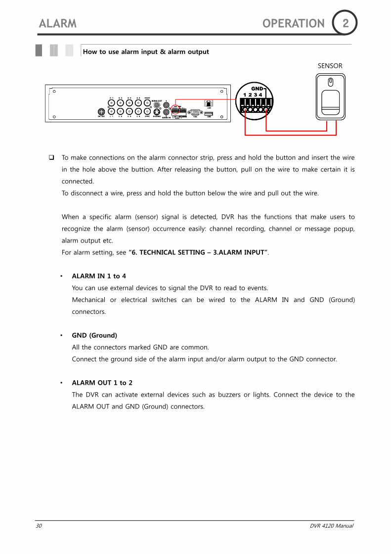
To make connections on the alarm connector strip, press and hold the button and insert the wire
in the hole above the buttion. After releasing the button, pull on the wire to make certain it is
connected.
To disconnect a wire, press and hold the button below the wire and pull out the wire.
When a specific alarm (sensor) signal is detected, DVR has the functions that make users to
recognize the alarm (sensor) occurrence easily: channel recording, channel or message popup,
alarm output etc.
For alarm setting, see “6. TECHNICAL SETTING – 3.ALARM INPUT”.
• ALARM IN 1 to 4
You can use external devices to signal the DVR to read to events.
Mechanical or electrical switches can be wired to the ALARM IN and GND (Ground)
connectors.
• GND (Ground)
All the connectors marked GND are common.
Connect the ground side of the alarm input and/or alarm output to the GND connector.
• ALARM OUT 1 to 2
The DVR can activate external devices such as buzzers or lights. Connect the device to the
ALARM OUT and GND (Ground) connectors.
How to use alarm input & alarm output
ALARM OPERATION 2
SENSOR
DVR 4120 Manual 31
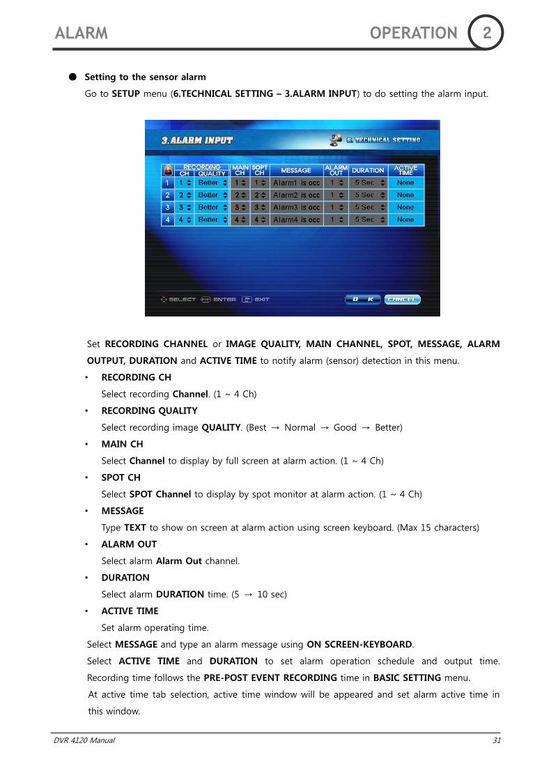
Setting to the sensor alarm
Go to SETUP menu (6.TECHNICAL SETTING – 3.ALARM INPUT) to do setting the alarm input.
Set RECORDING CHANNEL or IMAGE QUALITY, MAIN CHANNEL, SPOT, MESSAGE, ALARM
OUTPUT, DURATION and ACTIVE TIME to notify alarm (sensor) detection in this menu.
• RECORDING CH
Select recording Channel. (1 ~ 4 Ch)
• RECORDING QUALITY
Select recording image QUALITY. (Best → Normal → Good → Better)
• MAIN CH
Select Channel to display by full screen at alarm action. (1 ~ 4 Ch)
• SPOT CH
Select SPOT Channel to display by spot monitor at alarm action. (1 ~ 4 Ch)
• MESSAGE
Type TEXT to show on screen at alarm action using screen keyboard. (Max 15 characters)
• ALARM OUT
Select alarm Alarm Out channel.
• DURATION
Select alarm DURATION time. (5 → 10 sec)
• ACTIVE TIME
Set alarm operating time.
Select MESSAGE and type an alarm message using ON SCREEN-KEYBOARD.
Select ACTIVE TIME and DURATION to set alarm operation schedule and output time.
Recording time follows the PRE-POST EVENT RECORDING time in BASIC SETTING menu.
At active time tab selection, active time window will be appeared and set alarm active time in
this window.
ALARM OPERATION 2
32 DVR 4120 Manual
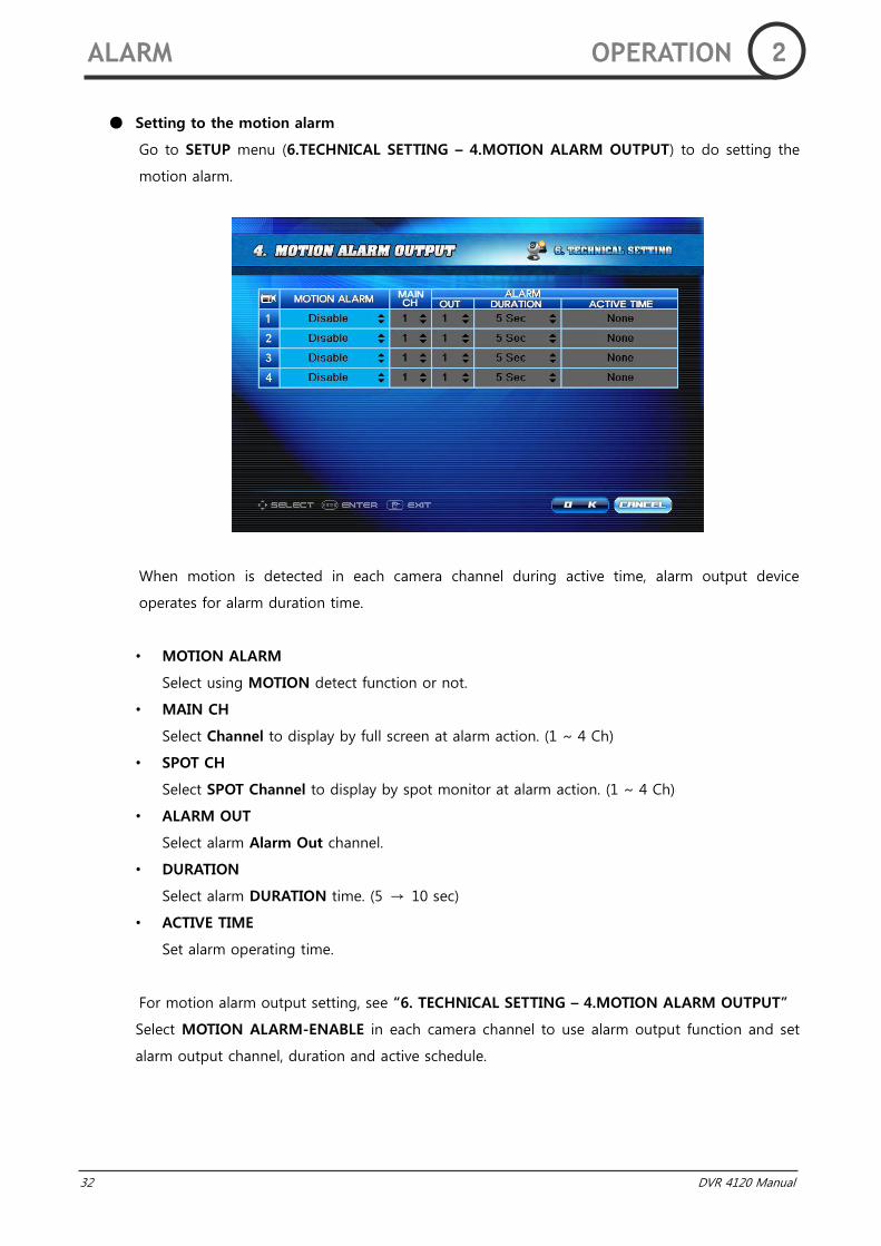
Setting to the motion alarm
Go to SETUP menu (6.TECHNICAL SETTING – 4.MOTION ALARM OUTPUT) to do setting the
motion alarm.
When motion is detected in each camera channel during active time, alarm output device
operates for alarm duration time.
• MOTION ALARM
Select using MOTION detect function or not.
• MAIN CH
Select Channel to display by full screen at alarm action. (1 ~ 4 Ch)
• SPOT CH
Select SPOT Channel to display by spot monitor at alarm action. (1 ~ 4 Ch)
• ALARM OUT
Select alarm Alarm Out channel.
• DURATION
Select alarm DURATION time. (5 → 10 sec)
• ACTIVE TIME
Set alarm operating time.
For motion alarm output setting, see “6. TECHNICAL SETTING – 4.MOTION ALARM OUTPUT”
Select MOTION ALARM-ENABLE in each camera channel to use alarm output function and set
alarm output channel, duration and active schedule.
ALARM OPERATION 2
DVR 4120 Manual 33
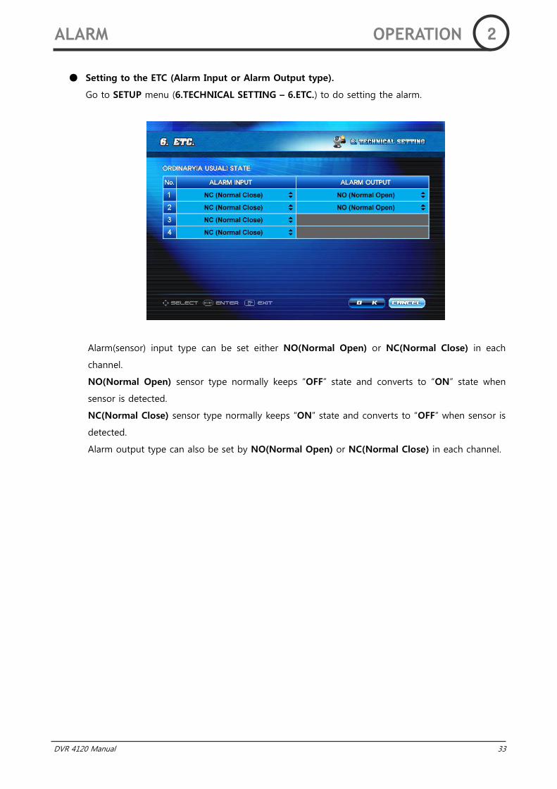
Setting to the ETC (Alarm Input or Alarm Output type).
Go to SETUP menu (6.TECHNICAL SETTING – 6.ETC.) to do setting the alarm.
Alarm(sensor) input type can be set either NO(Normal Open) or NC(Normal Close) in each
channel.
NO(Normal Open) sensor type normally keeps “OFF” state and converts to “ON” state when
sensor is detected.
NC(Normal Close) sensor type normally keeps “ON” state and converts to “OFF” when sensor is
detected.
Alarm output type can also be set by NO(Normal Open) or NC(Normal Close) in each channel.
ALARM OPERATION 2
34 DVR 4120 Manual
DVR 4120 Manual 35
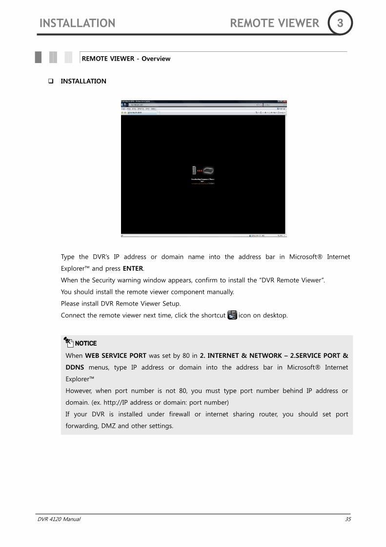
INSTALLATION
Type the DVR‟s IP address or domain name into the address bar in Microsoft® Internet
Explorer™ and press ENTER.
When the Security warning window appears, confirm to install the “DVR Remote Viewer”.
You should install the remote viewer component manually.
Please install DVR Remote Viewer Setup.
Connect the remote viewer next time, click the shortcut icon on desktop.
REMOTE VIEWER - Overview
NOTICE
When WEB SERVICE PORT was set by 80 in 2. INTERNET & NETWORK – 2.SERVICE PORT &
DDNS menus, type IP address or domain into the address bar in Microsoft® Internet
Explorer™
However, when port number is not 80, you must type port number behind IP address or
domain. (ex. http://IP address or domain: port number)
If your DVR is installed under firewall or internet sharing router, you should set port
forwarding, DMZ and other settings.
INSTALLATION REMOTE VIEWER 3
36 DVR 4120 Manual
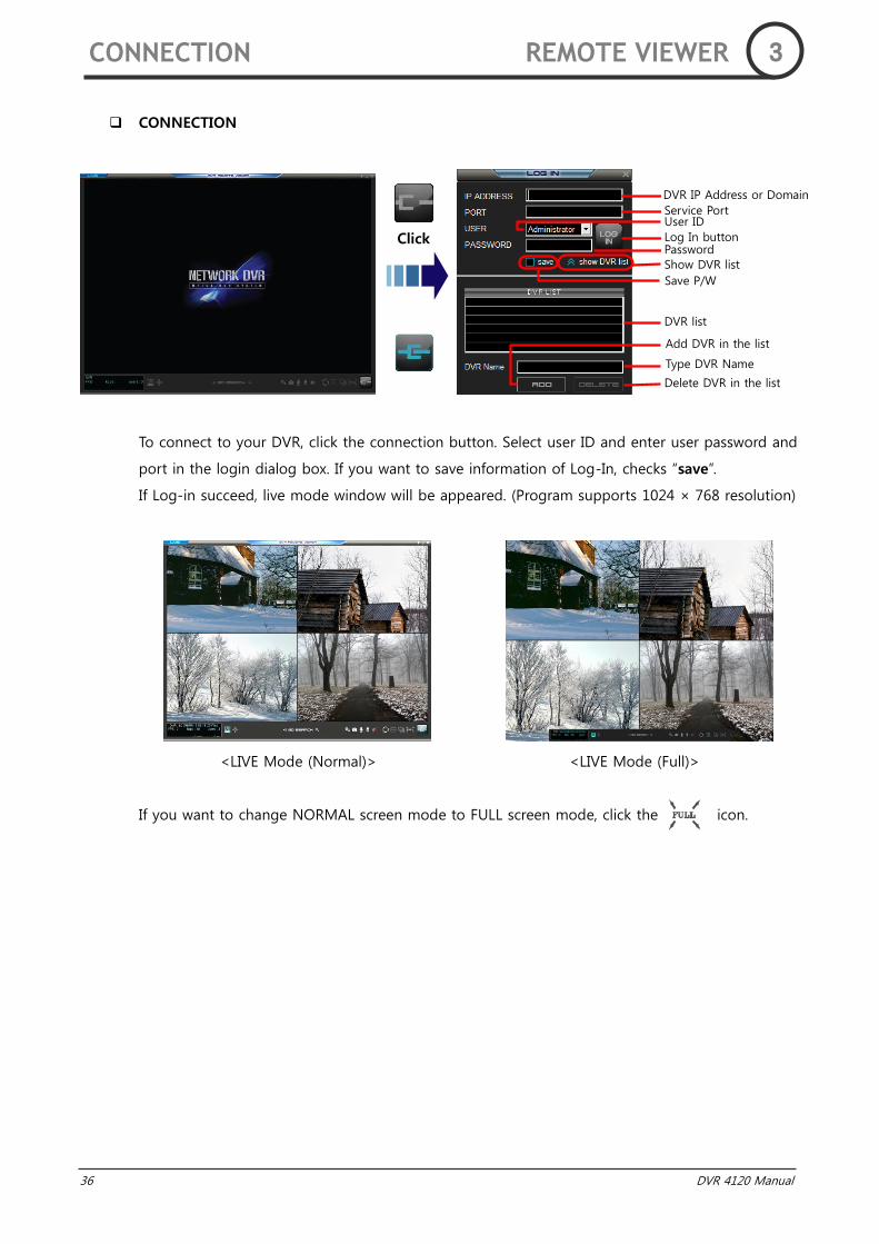
CONNECTION
To connect to your DVR, click the connection button. Select user ID and enter user password and
port in the login dialog box. If you want to save information of Log-In, checks “save”.
If Log-in succeed, live mode window will be appeared. (Program supports 1024 × 768 resolution)
<LIVE Mode (Normal)> <LIVE Mode (Full)>
If you want to change NORMAL screen mode to FULL screen mode, click the icon.
CONNECTION REMOTE VIEWER 3
DVR IP Address or Domain
Service Port
Delete DVR in the list
User ID
Log In button Password
Show DVR list
Save P/W
DVR list
Add DVR in the list
Type DVR Name
Click
DVR 4120 Manual 37
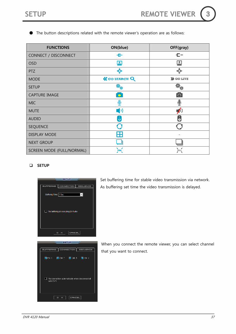
The button descriptions related with the remote viewer‟s operation are as follows:
FUNCTIONS ON(blue) OFF(gray)
CONNECT / DISCONNECT
OSD
PTZ
MODE
SETUP
CAPTURE IMAGE
MIC
MUTE
AUDIO
SEQUENCE
DISPLAY MODE -
NEXT GROUP
SCREEN MODE (FULL/NORMAL)
SETUP
Set buffering time for stable video transmission via network.
As buffering set time the video transmission is delayed.
When you connect the remote viewer, you can select channel
that you want to connect.
SETUP REMOTE VIEWER 3

38 DVR 4120 Manual
Set Duration time (0, 1, 2, 4, 8, 15, 30, 60 Sec).
If you check “Use the sequence mode at start up”,
sequence mode will be started when you connect to the A.I.
DVR.
STATUS
<DVR Information Window>
AUDIO SETUP
<MUTE> <1CH> <2CH> <1&2CH>
You can set audio output. (1 channel or 2 channel or 1 & 2 channels Mix)
PTZ CONTROL
Please change display mode to 1 channel screen mode (want to control channel).
Click the PTZ icon and you can control Camera SPEED, FOCUS, DIRECTION, AUTO FOCUS and
ZOOM at upper window.
When you want to exit PTZ mode, click (search mode) or , (live mode) button.
SETUP/STATUS/AUDIO/PTZ REMOTE VIEWER 3
DVR Name Date/Time
Number of connecter
Current bandwidth
Transmission network bandwidth
Transmit frames per
second
graph
DVR 4120 Manual 39
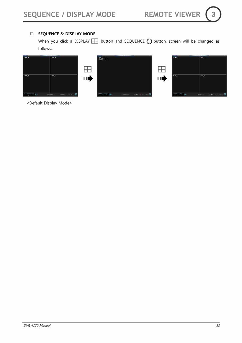
SEQUENCE & DISPLAY MODE
When you click a DISPLAY button and SEQUENCE button, screen will be changed as
follows:
SEQUENCE / DISPLAY MODE REMOTE VIEWER 3
<Default Display Mode>
40 DVR 4120 Manual
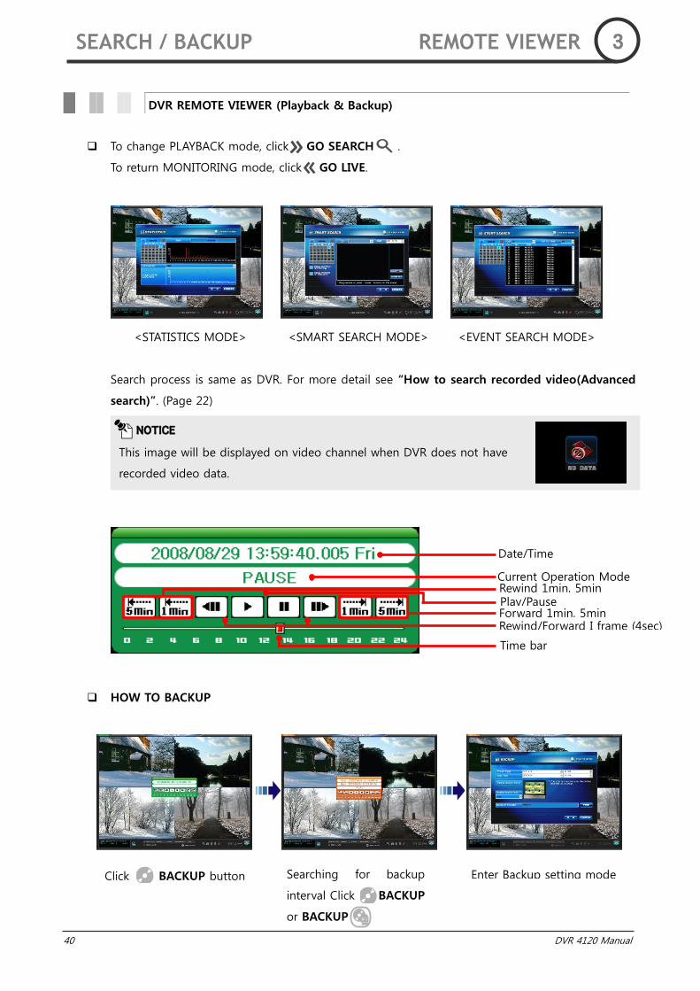
To change PLAYBACK mode, click GO SEARCH .
To return MONITORING mode, click GO LIVE.
<STATISTICS MODE> <SMART SEARCH MODE> <EVENT SEARCH MODE>
Search process is same as DVR. For more detail see “How to search recorded video(Advanced
search)”. (Page 22)
HOW TO BACKUP
DVR REMOTE VIEWER (Playback & Backup)
NOTICE
This image will be displayed on video channel when DVR does not have
recorded video data.
Date/Time
Current Operation Mode Rewind 1min, 5min
Forward 1min, 5min Rewind/Forward I frame (4sec)
Time bar
Play/Pause
Click BACKUP button Searching for backup
interval Click BACKUP
or BACKUP
Enter Backup setting mode
SEARCH / BACKUP REMOTE VIEWER 3
DVR 4120 Manual 41
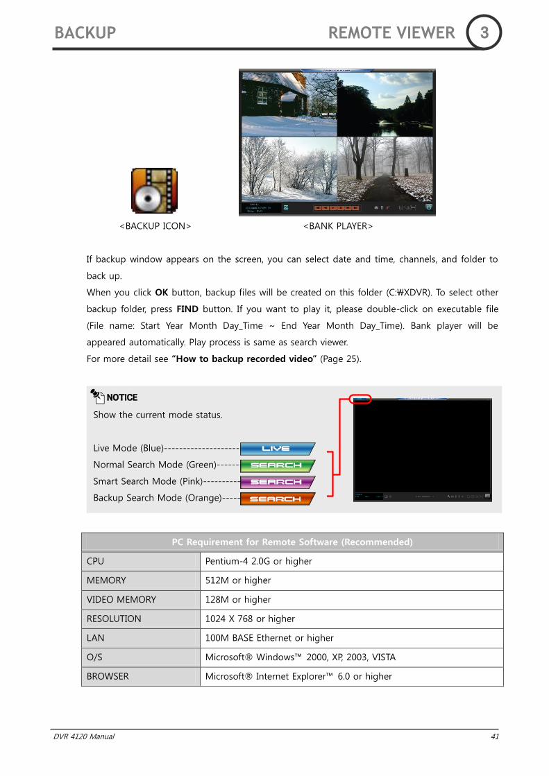
<BACKUP ICON> <BANK PLAYER>
If backup window appears on the screen, you can select date and time, channels, and folder to
back up.
When you click OK button, backup files will be created on this folder (C:\XDVR). To select other
backup folder, press FIND button. If you want to play it, please double-click on executable file
(File name: Start Year Month Day_Time ~ End Year Month Day_Time). Bank player will be
appeared automatically. Play process is same as search viewer.
For more detail see “How to backup recorded video” (Page 25).
PC Requirement for Remote Software (Recommended)
CPU Pentium-4 2.0G or higher
MEMORY 512M or higher
VIDEO MEMORY 128M or higher
RESOLUTION 1024 X 768 or higher
LAN 100M BASE Ethernet or higher
O/S Microsoft® Windows™ 2000, XP, 2003, VISTA
BROWSER Microsoft® Internet Explorer™ 6.0 or higher
NOTICE
Show the current mode status.
Live Mode (Blue)-----------------------
Normal Search Mode (Green)-------
Smart Search Mode (Pink)-----------
Backup Search Mode (Orange)--------
BACKUP REMOTE VIEWER 3
42 DVR 4120 Manual
DVR 4120 Manual 43
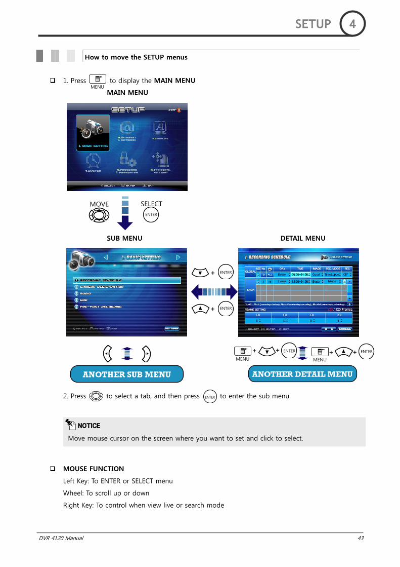
1. Press to display the MAIN MENU
MAIN MENU
SUB MENU DETAIL MENU
2. Press to select a tab, and then press to enter the sub menu.
MOUSE FUNCTION
Left Key: To ENTER or SELECT menu
Wheel: To scroll up or down
Right Key: To control when view live or search mode
How to move the SETUP menus
NOTICE
Move mouse cursor on the screen where you want to set and click to select.
SETUP 4
MENU
MOVE
ENTER
SELECT
+ ENTER
+ ENTER
MENU
+ + ENTER
MENU
ENTER + +
ENTER
44 DVR 4120 Manual
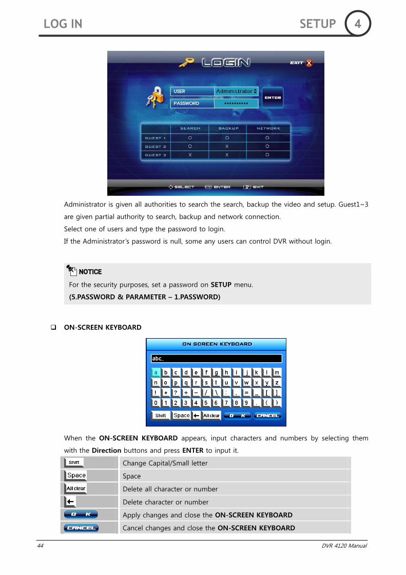
Administrator is given all authorities to search the search, backup the video and setup. Guest1~3
are given partial authority to search, backup and network connection.
Select one of users and type the password to login.
If the Administrator‟s password is null, some any users can control DVR without login.
ON-SCREEN KEYBOARD
When the ON-SCREEN KEYBOARD appears, input characters and numbers by selecting them
with the Direction buttons and press ENTER to input it.
Change Capital/Small letter
Space
Delete all character or number
Delete character or number
Apply changes and close the ON-SCREEN KEYBOARD
Cancel changes and close the ON-SCREEN KEYBOARD
NOTICE
For the security purposes, set a password on SETUP menu.
(5.PASSWORD & PARAMETER – 1.PASSWORD)
LOG IN SETUP 4
DVR 4120 Manual 45
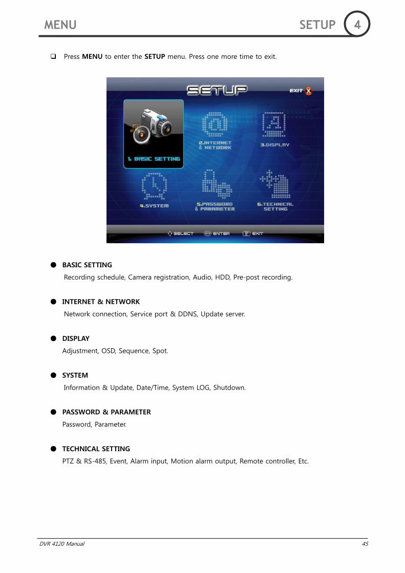
Press MENU to enter the SETUP menu. Press one more time to exit.
BASIC SETTING
Recording schedule, Camera registration, Audio, HDD, Pre-post recording.
INTERNET & NETWORK
Network connection, Service port & DDNS, Update server.
DISPLAY
Adjustment, OSD, Sequence, Spot.
SYSTEM
Information & Update, Date/Time, System LOG, Shutdown.
PASSWORD & PARAMETER
Password, Parameter.
TECHNICAL SETTING
PTZ & RS-485, Event, Alarm input, Motion alarm output, Remote controller, Etc.
MENU SETUP 4
46 DVR 4120 Manual
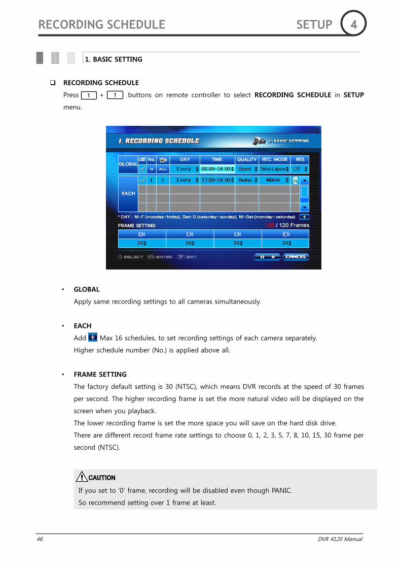
RECORDING SCHEDULE
Press + buttons on remote controller to select RECORDING SCHEDULE in SETUP
menu.
• GLOBAL
Apply same recording settings to all cameras simultaneously.
• EACH
Add Max 16 schedules, to set recording settings of each camera separately.
Higher schedule number (No.) is applied above all.
• FRAME SETTING
The factory default setting is 30 (NTSC), which means DVR records at the speed of 30 frames
per second. The higher recording frame is set the more natural video will be displayed on the
screen when you playback.
The lower recording frame is set the more space you will save on the hard disk drive.
There are different record frame rate settings to choose 0, 1, 2, 3, 5, 7, 8, 10, 15, 30 frame per
second (NTSC).
1. BASIC SETTING
CAUTION
If you set to „0‟ frame, recording will be disabled even though PANIC.
So recommend setting over 1 frame at least.
RECORDING SCHEDULE SETUP 4
DVR 4120 Manual 47
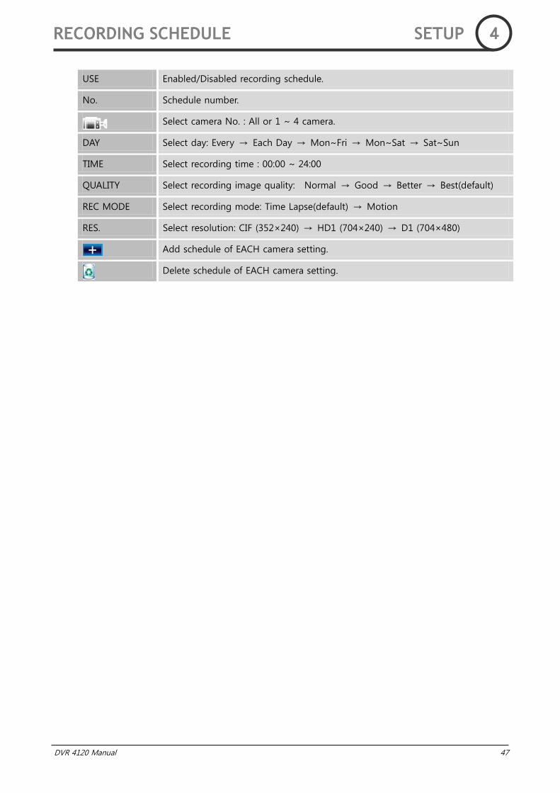
USE Enabled/Disabled recording schedule.
No. Schedule number.
Select camera No. : All or 1 ~ 4 camera.
DAY Select day: Every → Each Day → Mon~Fri → Mon~Sat → Sat~Sun
TIME Select recording time : 00:00 ~ 24:00
QUALITY Select recording image quality: Normal → Good → Better → Best(default)
REC MODE Select recording mode: Time Lapse(default) → Motion
RES. Select resolution: CIF (352×240) → HD1 (704×240) → D1 (704×480)
Add schedule of EACH camera setting.
Delete schedule of EACH camera setting.
RECORDING SCHEDULE SETUP 4

48 DVR 4120 Manual
CAMERA REGISTRATION
Press + buttons on remote controller to select CAMERA REGISTRATION in SETUP
menu.
• NAME
Edit NAME (Max 15 characters). Use the ON-SCREEN KEYBOARD to enter a specific camera‟s
name.
• VIDEO LOSS
Select Beep On or Beep Off.
Beep On mode will sound a beep from an internal buzzer if the camera signal is removed or
the camera power is off.
CAMERA REGISTRATION SETUP 4
DVR 4120 Manual 49
• PRIVACY
Select whether to display images on the monitoring screen for privacy. (On/Off) PRIVACY
mode doesn‟t show the monitoring video but the video can be recorded and played in the
search mode normally.
• MOTION AREA
You can set the motion detection area for motion recording mode in this menu.
If you select the motion area, it converts into the upper screen.
Click or drag the area you want to detect or press enter on the remote controller.
You can SELECT/CLEAR ALL in context menu.
And the area chosen will mark with blue color. It records when the motion happen in set area
with recording mode. Areas that happen to motion are cyan block.
• SENSITIVITY
Motion sensitivity is marked by Normal(default) → Sensitive → Most → Insensitive
NOTICE
If you set to „0‟ frame, you cannot set MOTION AREA and SENSITIVITY.
CAMERA REGISTRATION SETUP 4

50 DVR 4120 Manual
AUDIO
Press + buttons on remote controller to select AUDIO in SETUP menu.
• LIVE(SPEAKER)
If the speaker is installed, you can select whether to turn sound On/Off via speaker on live
mode.
• RECORDING
If the RECORDING is On, the audio will be recorded with the video together.
NOTICE
Audio is supported Max. 2 channel.
AUDIO SETUP 4
DVR 4120 Manual 51
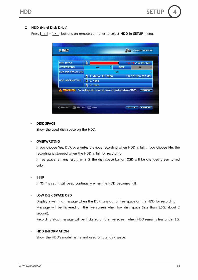
HDD (Hard Disk Drive)
Press + buttons on remote controller to select HDD in SETUP menu.
• DISK SPACE
Show the used disk space on the HDD.
• OVERWRITING
If you choose Yes, DVR overwrites previous recording when HDD is full. If you choose No, the
recording is stopped when the HDD is full for recording.
If free space remains less than 2 G, the disk space bar on OSD will be changed green to red
color.
• BEEP
If “On” is set, it will beep continually when the HDD becomes full.
• LOW DISK SPACE OSD
Display a warning message when the DVR runs out of free space on the HDD for recording.
Message will be flickered on the live screen when low disk space (less than 1.5G, about 2
second).
Recording stop message will be flickered on the live screen when HDD remains less under 1G.
• HDD INFORMATION
Show the HDD‟s model name and used & total disk space.
HDD SETUP 4
52 DVR 4120 Manual
• FORMAT
If you format the hard drive, it will erase all the recorded data and log on the HDD.
CAUTION
If you click FORMAT, warning window will be displayed. Once the HDD is formatted, all
recorded data, system logs and event logs will be lost.
HDD SETUP 4
DVR 4120 Manual 53
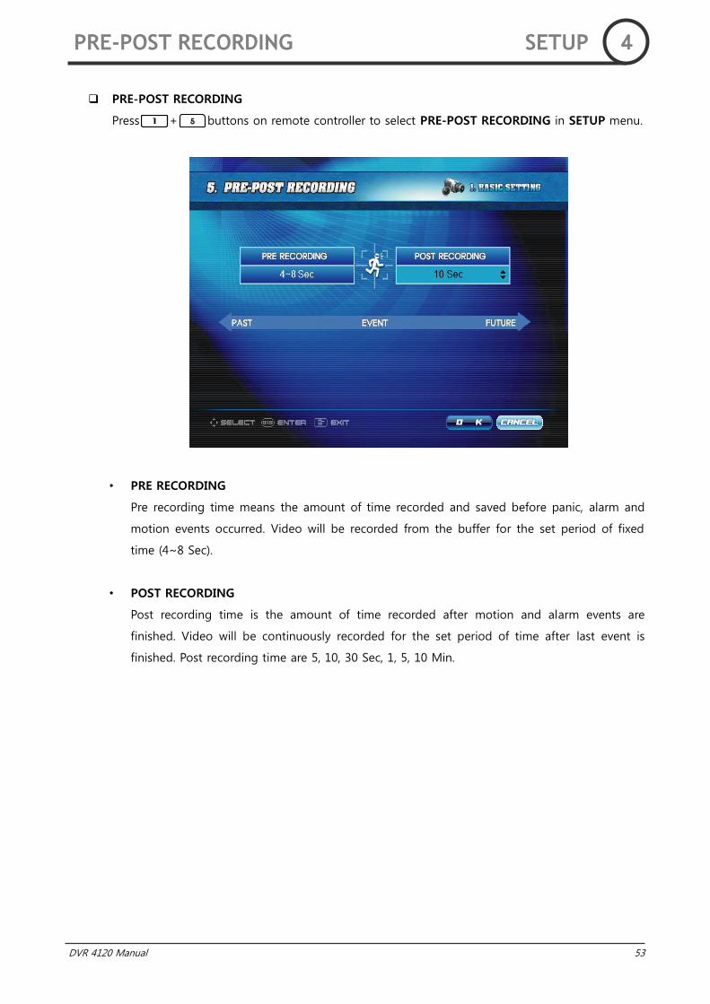
PRE-POST RECORDING
Press + buttons on remote controller to select PRE-POST RECORDING in SETUP menu.
• PRE RECORDING
Pre recording time means the amount of time recorded and saved before panic, alarm and
motion events occurred. Video will be recorded from the buffer for the set period of fixed
time (4~8 Sec).
• POST RECORDING
Post recording time is the amount of time recorded after motion and alarm events are
finished. Video will be continuously recorded for the set period of time after last event is
finished. Post recording time are 5, 10, 30 Sec, 1, 5, 10 Min.
PRE-POST RECORDING SETUP 4
54 DVR 4120 Manual
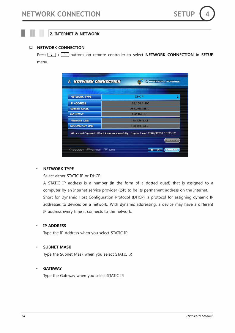
NETWORK CONNECTION
Press + buttons on remote controller to select NETWORK CONNECTION in SETUP
menu.
• NETWORK TYPE
Select either STATIC IP or DHCP.
A STATIC IP address is a number (in the form of a dotted quad) that is assigned to a
computer by an Internet service provider (ISP) to be its permanent address on the Internet.
Short for Dynamic Host Configuration Protocol (DHCP), a protocol for assigning dynamic IP
addresses to devices on a network. With dynamic addressing, a device may have a different
IP address every time it connects to the network.
• IP ADDRESS
Type the IP Address when you select STATIC IP.
• SUBNET MASK
Type the Subnet Mask when you select STATIC IP.
• GATEWAY
Type the Gateway when you select STATIC IP.
2. INTERNET & NETWORK
NETWORK CONNECTION SETUP 4
DVR 4120 Manual 55
• PRIMARY DNS
Primary DNS is used to refer the DVR‟s IP address to a preferred domain name.
• SECONDARY DNS
Secondary DNS is used to refer the DVR‟s IP address for backup domain name.
NOTICE
When you select DHCP and press APPLY button , allocated IP information will be
displayed.
NETWORK CONNECTION SETUP 4
56 DVR 4120 Manual
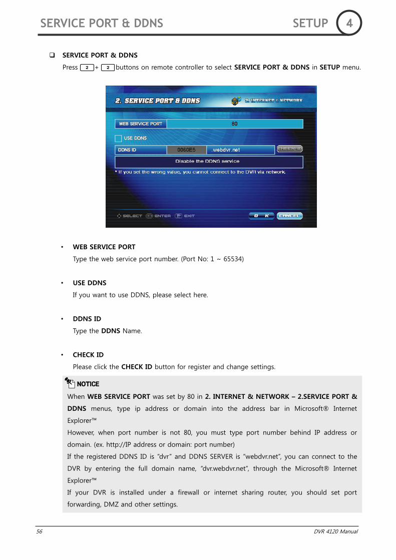
SERVICE PORT & DDNS
Press + buttons on remote controller to select SERVICE PORT & DDNS in SETUP menu.
• WEB SERVICE PORT
Type the web service port number. (Port No: 1 ~ 65534)
• USE DDNS
If you want to use DDNS, please select here.
• DDNS ID
Type the DDNS Name.
• CHECK ID
Please click the CHECK ID button for register and change settings.
NOTICE
When WEB SERVICE PORT was set by 80 in 2. INTERNET & NETWORK – 2.SERVICE PORT &
DDNS menus, type ip address or domain into the address bar in Microsoft® Internet
Explorer™
However, when port number is not 80, you must type port number behind IP address or
domain. (ex. http://IP address or domain: port number)
If the registered DDNS ID is “dvr” and DDNS SERVER is “webdvr.net”, you can connect to the
DVR by entering the full domain name, “dvr.webdvr.net”, through the Microsoft® Internet
Explorer™
If your DVR is installed under a firewall or internet sharing router, you should set port
forwarding, DMZ and other settings.
SERVICE PORT & DDNS SETUP 4
DVR 4120 Manual 57
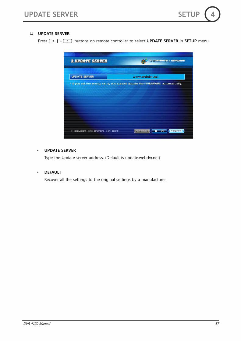
UPDATE SERVER
Press + buttons on remote controller to select UPDATE SERVER in SETUP menu.
• UPDATE SERVER
Type the Update server address. (Default is update.webdvr.net)
• DEFAULT
Recover all the settings to the original settings by a manufacturer.
UPDATE SERVER SETUP 4
58 DVR 4120 Manual
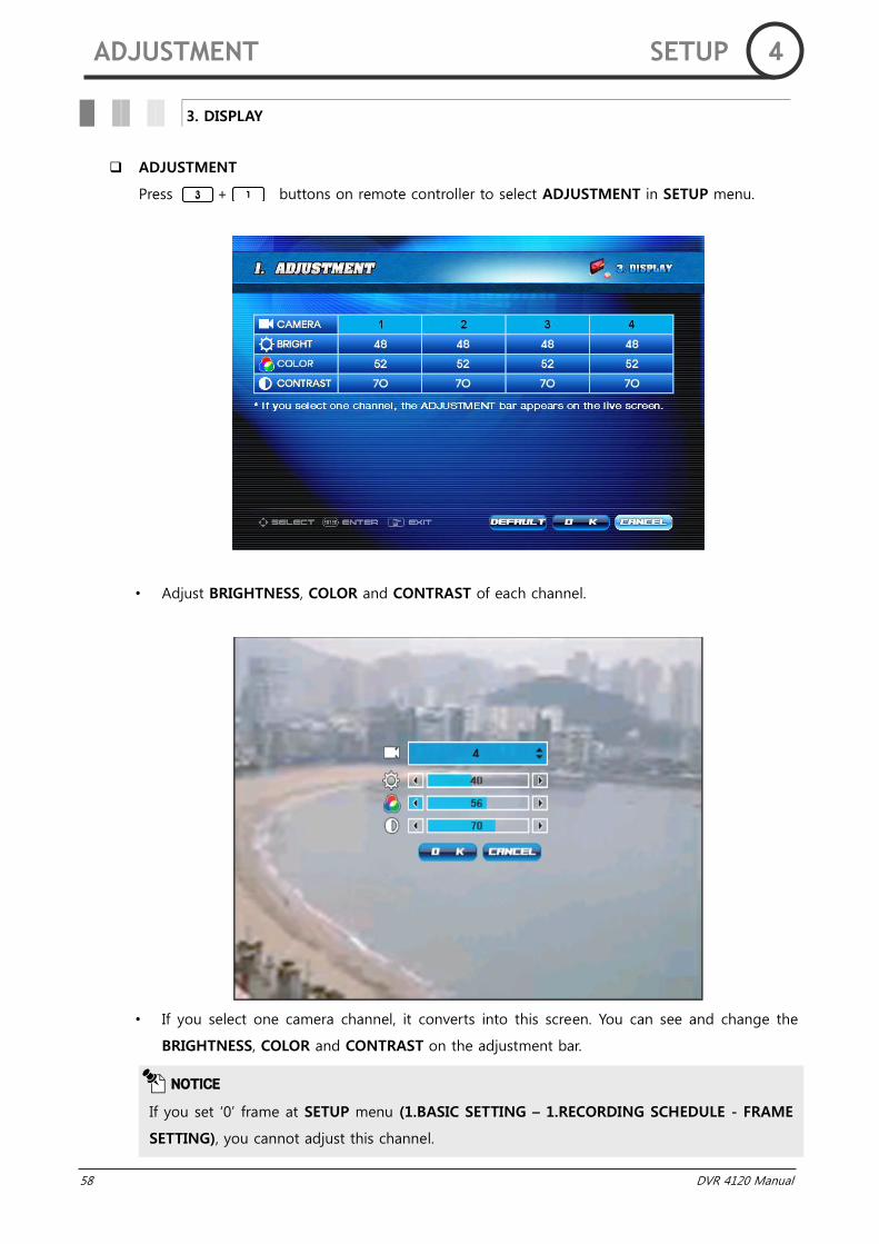
ADJUSTMENT
Press + buttons on remote controller to select ADJUSTMENT in SETUP menu.
• Adjust BRIGHTNESS, COLOR and CONTRAST of each channel.
• If you select one camera channel, it converts into this screen. You can see and change the
BRIGHTNESS, COLOR and CONTRAST on the adjustment bar.
3. DISPLAY
NOTICE
If you set „0‟ frame at SETUP menu (1.BASIC SETTING – 1.RECORDING SCHEDULE - FRAME
SETTING), you cannot adjust this channel.
ADJUSTMENT SETUP 4

DVR 4120 Manual 59
OSD
Press + buttons on remote controller to select OSD in SETUP menu.
• CH INFO
Show or hide the camera name on the display monitor.
• DATE / TIME
Show or hide the current date / time on the display monitor.
• DISK SPACE
Show or hide the disk space bar.
• RECORDING MODE
Show or hide the recording mode icon on the display monitor.
NOTICE
If DATE/TIME OSD is set to Off mode, audio recording and sequence icon will be hidden
together.
OSD SETUP 4

60 DVR 4120 Manual
SEQUENCE
Press + buttons on remote controller to select SEQUENCE in SETUP menu.
• DURATION
On SEQUENCE mode, each channel is displayed on the screen for the preset duration. (Max.
60 Sec) And if you set to „0‟ second, screen mode will be skipped over.
On SEQUENCE mode, a SEQUENCE icon is displayed on live screen.
• USE THE SEQUENCE MODE AT STARTUP
Select whether to use the SEQUENCE mode automatically when DVR starts up.
NOTICE
You cannot set „0 Sec‟ all of DURATION.
You cannot also set DURATION only 4 Channel mode.
SEQUENCE SETUP 4
DVR 4120 Manual 61
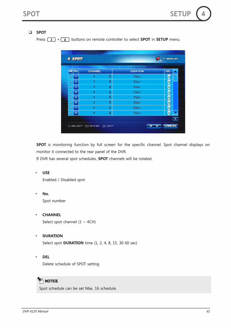
SPOT
Press + buttons on remote controller to select SPOT in SETUP menu.
SPOT is monitoring function by full screen for the specific channel. Spot channel displays on
monitor it connected to the rear panel of the DVR.
If DVR has several spot schedules, SPOT channels will be rotated.
• USE
Enabled / Disabled spot
• No.
Spot number
• CHANNEL
Select spot channel (1 ~ 4CH)
• DURATION
Select spot DURATION time (1, 2, 4, 8, 15, 30 60 sec)
• DEL
Delete schedule of SPOT setting
NOTICE
Spot schedule can be set Max. 16 schedule.
SPOT SETUP 4
62 DVR 4120 Manual
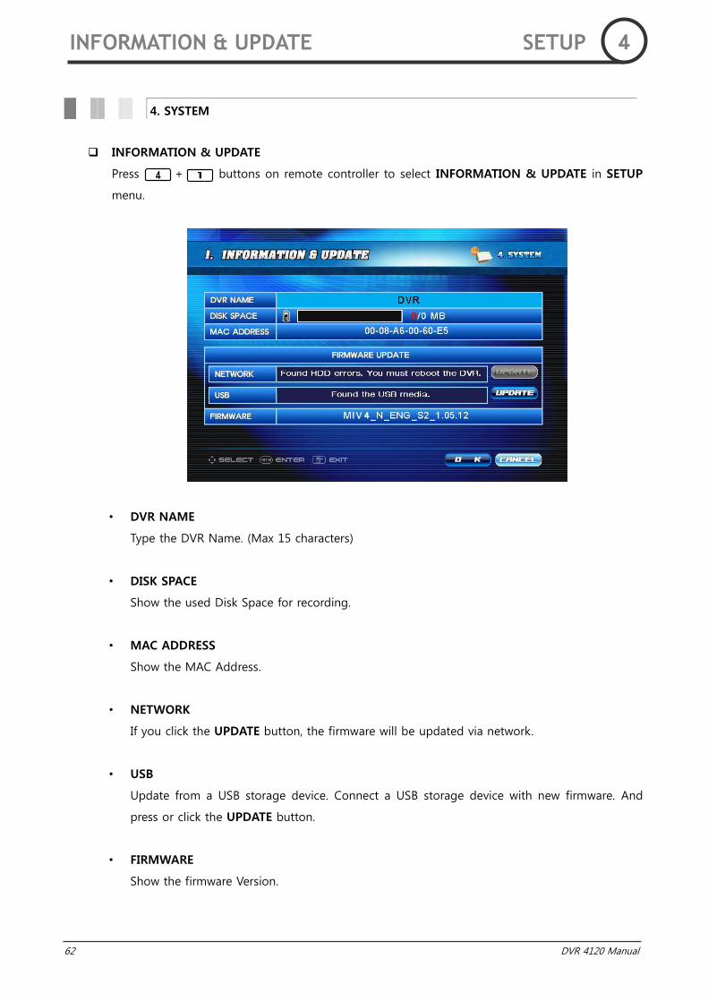
INFORMATION & UPDATE
Press + buttons on remote controller to select INFORMATION & UPDATE in SETUP
menu.
• DVR NAME
Type the DVR Name. (Max 15 characters)
• DISK SPACE
Show the used Disk Space for recording.
• MAC ADDRESS
Show the MAC Address.
• NETWORK
If you click the UPDATE button, the firmware will be updated via network.
• USB
Update from a USB storage device. Connect a USB storage device with new firmware. And
press or click the UPDATE button.
• FIRMWARE
Show the firmware Version.
4. SYSTEM
INFORMATION & UPDATE SETUP 4

DVR 4120 Manual 63
How to update via network
If your DVR connect with internet, DVR will check the new firmware automatically by periods.
Updates direction message blinks on the OSD if there is firmware to update and shortcut
icon is displayed on the right bottom of the screen.
Click the icon or go to SETUP menu (4.SYSTEM – 1.INFORMATION & UPDATE).
Then click the NETWORK UPDATE button. UPDATE will be progressed automatically.
How to update via USB storage
Select the firmware file from the list and press or click OK button.
Once the firmware has been successfully updated, the DVR will be rebooted to apply changes
automatically.
Before updating, firmware files (cod-file) should be copied into a “Firmware” folder on the USB
storage device. If you connect several USB storage devices with firmware, the DVR will only
recognize of a first connecting USB storage device.
NOTICE
USB storage device‟s file system should be FAT32.
WARNING
Please note that because updating firmware has potential risk, please do it with caution!
Do not turn off power or reset your system at this stage!
INFORMATION & UPDATE SETUP 4
64 DVR 4120 Manual
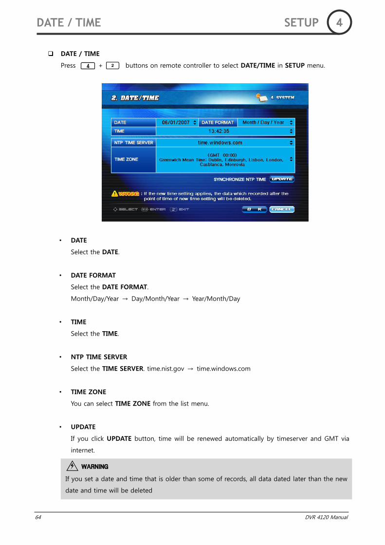
DATE / TIME
Press + buttons on remote controller to select DATE/TIME in SETUP menu.
• DATE
Select the DATE.
• DATE FORMAT
Select the DATE FORMAT.
Month/Day/Year → Day/Month/Year → Year/Month/Day
• TIME
Select the TIME.
• NTP TIME SERVER
Select the TIME SERVER. time.nist.gov → time.windows.com
• TIME ZONE
You can select TIME ZONE from the list menu.
• UPDATE
If you click UPDATE button, time will be renewed automatically by timeserver and GMT via
internet.
WARNING
If you set a date and time that is older than some of records, all data dated later than the new
date and time will be deleted
DATE / TIME SETUP 4
DVR 4120 Manual 65
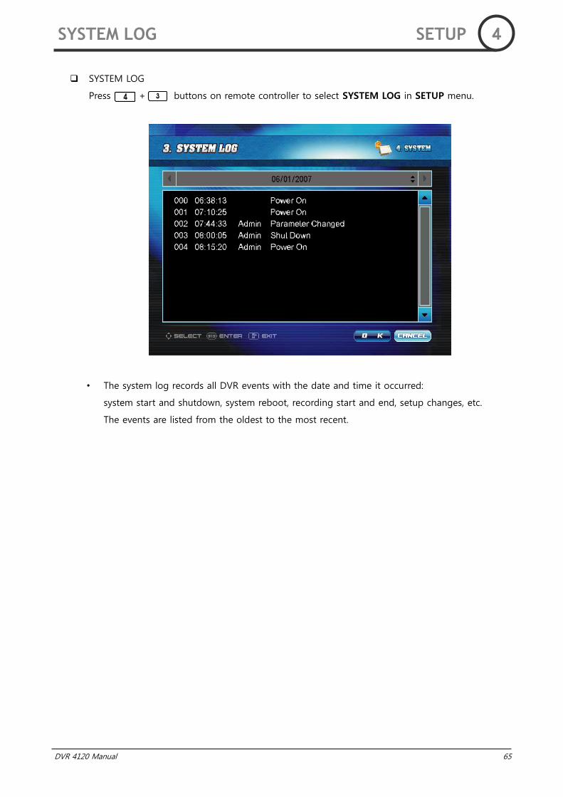
SYSTEM LOG
Press + buttons on remote controller to select SYSTEM LOG in SETUP menu.
• The system log records all DVR events with the date and time it occurred:
system start and shutdown, system reboot, recording start and end, setup changes, etc.
The events are listed from the oldest to the most recent.
SYSTEM LOG SETUP 4
66 DVR 4120 Manual
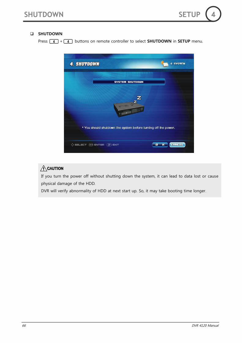
SHUTDOWN
Press + buttons on remote controller to select SHUTDOWN in SETUP menu.
CAUTION
If you turn the power off without shutting down the system, it can lead to data lost or cause
physical damage of the HDD.
DVR will verify abnormality of HDD at next start up. So, it may take booting time longer.
SHUTDOWN SETUP 4
DVR 4120 Manual 67
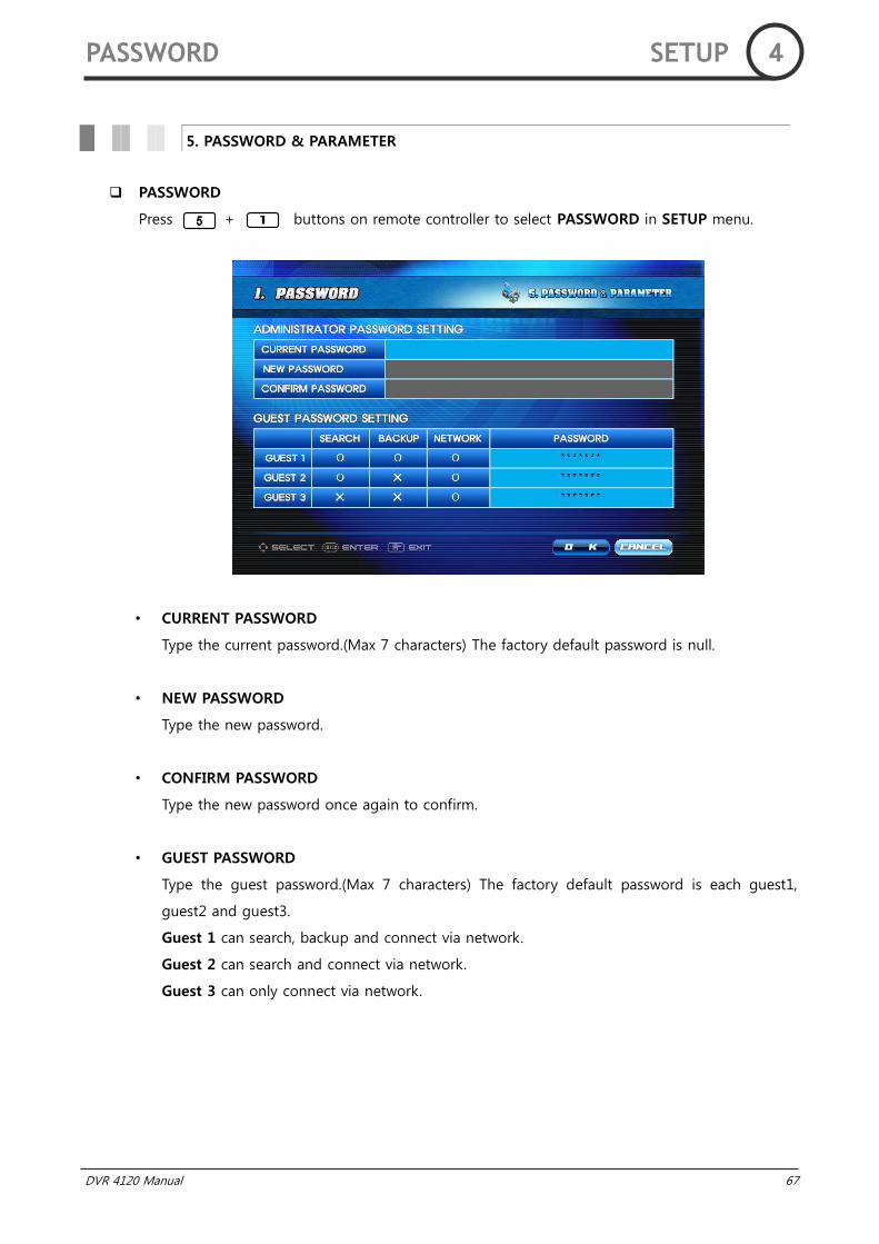
PASSWORD
Press + buttons on remote controller to select PASSWORD in SETUP menu.
• CURRENT PASSWORD
Type the current password.(Max 7 characters) The factory default password is null.
• NEW PASSWORD
Type the new password.
• CONFIRM PASSWORD
Type the new password once again to confirm.
• GUEST PASSWORD
Type the guest password.(Max 7 characters) The factory default password is each guest1,
guest2 and guest3.
Guest 1 can search, backup and connect via network.
Guest 2 can search and connect via network.
Guest 3 can only connect via network.
5. PASSWORD & PARAMETER
PASSWORD SETUP 4
68 DVR 4120 Manual
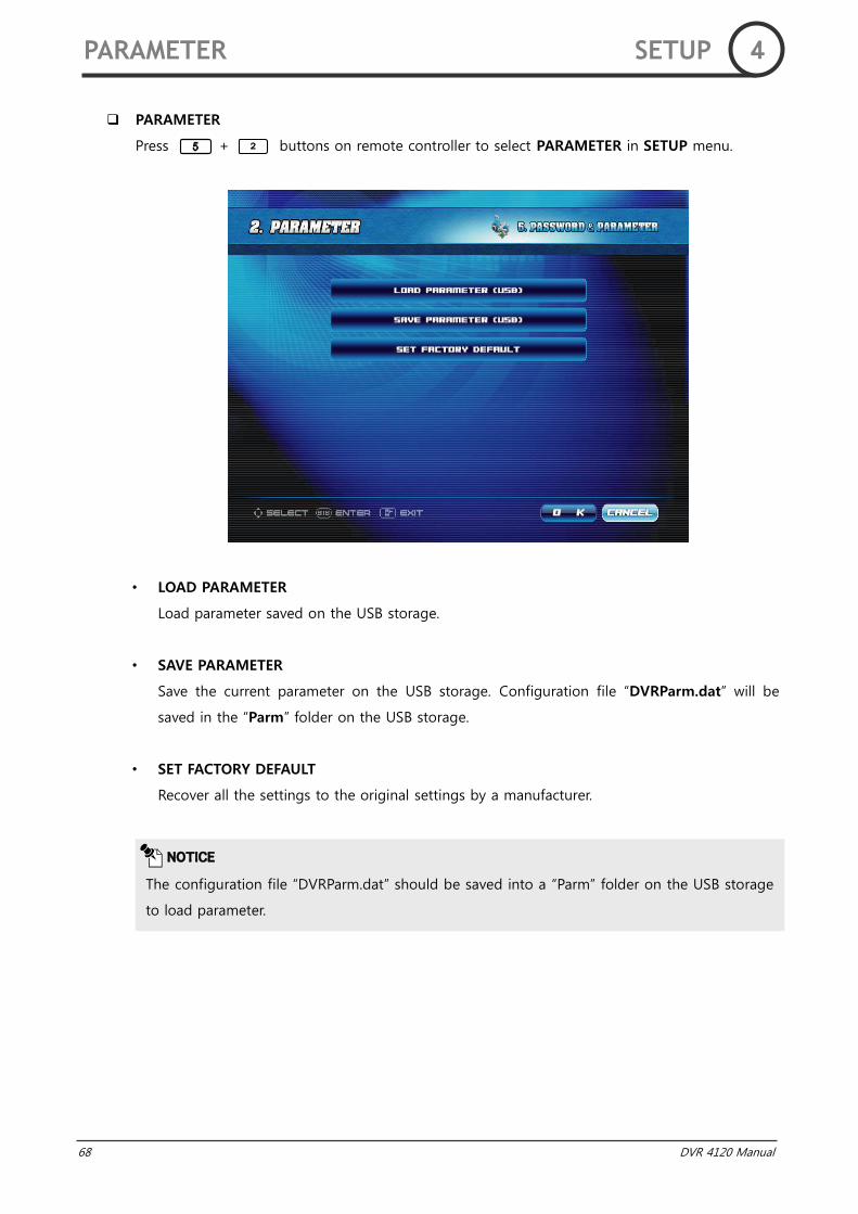
PARAMETER
Press + buttons on remote controller to select PARAMETER in SETUP menu.
• LOAD PARAMETER
Load parameter saved on the USB storage.
• SAVE PARAMETER
Save the current parameter on the USB storage. Configuration file “DVRParm.dat” will be
saved in the “Parm” folder on the USB storage.
• SET FACTORY DEFAULT
Recover all the settings to the original settings by a manufacturer.
NOTICE
The configuration file “DVRParm.dat” should be saved into a “Parm” folder on the USB storage
to load parameter.
PARAMETER SETUP 4

DVR 4120 Manual 69
PTZ & RS-485
Press + buttons on remote controller to select PTZ in SETUP menu.
• PTZ ID
Select the PTZ ID. (0 ~ 255)
• PROTOCOL
Select the PROTOCOL. (Default is None.)
• BAUD RATE
Select the BAUD RATE. (Default is 9600.)
9600 → 19200 → 38400 → 57600 → 115200 → 1200 → 2400 → 4800
Baud rate means the speed of between the devices.
• DATA BIT
Select DATA BIT. (Default is 8.)
Data bit means the number of data bit.
• STOP BIT
Select 1 or 2 the STOP BIT. (Default is 1.)
Stop bit means the number of stop bit between data transfer.
6. TECHNICAL SETTING
PTZ & RS-485 SETUP 4

70 DVR 4120 Manual
• PARITY
Select the PARITY. (Default is No Parity.)
No Parity → Odd Parity → Even Parity
Parity means the error check bit while the data is transferring.
NOTICE
All of settings must be the same as the PTZ camera‟s settings.
The settings are different from the camera‟s models. See the PTZ camera‟s manual for setting
of RS-485.
PTZ & RS-485 SETUP 4
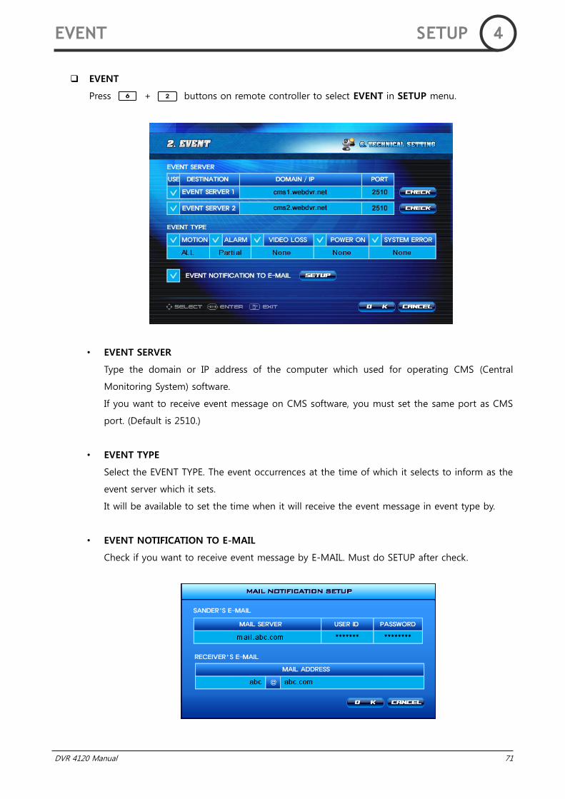
DVR 4120 Manual 71
EVENT
Press + buttons on remote controller to select EVENT in SETUP menu.
• EVENT SERVER
Type the domain or IP address of the computer which used for operating CMS (Central
Monitoring System) software.
If you want to receive event message on CMS software, you must set the same port as CMS
port. (Default is 2510.)
• EVENT TYPE
Select the EVENT TYPE. The event occurrences at the time of which it selects to inform as the
event server which it sets.
It will be available to set the time when it will receive the event message in event type by.
• EVENT NOTIFICATION TO E-MAIL
Check if you want to receive event message by E-MAIL. Must do SETUP after check.
EVENT SETUP 4

72 DVR 4120 Manual
• MAIL SERVER
Type sender‟s MAIL SERVER address. If you do not type mail server address, event message
mail will be classified by spam.
• USER ID & P/W
Type mail server's USER ID and PASSWORD.
• MAIL ADDRESS
Type the E-mail address to receive event message mail.
EVENT SETUP 4
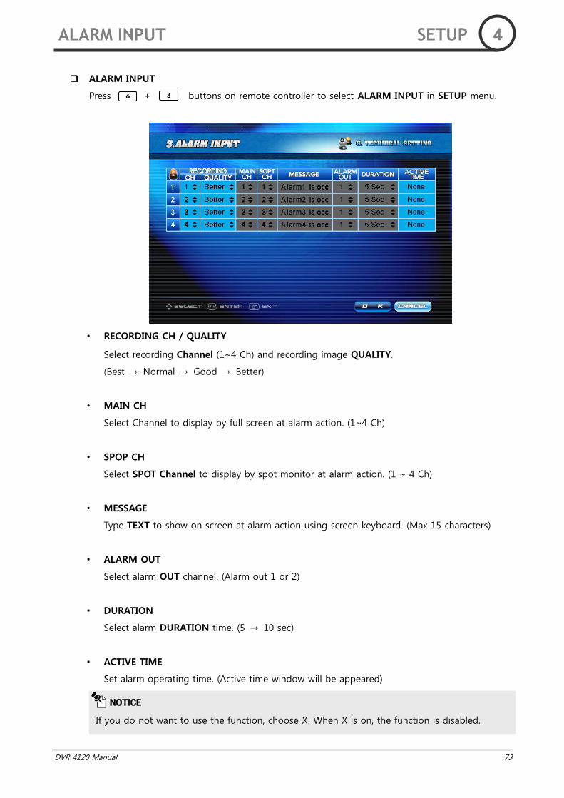
DVR 4120 Manual 73
ALARM INPUT
Press + buttons on remote controller to select ALARM INPUT in SETUP menu.
• RECORDING CH / QUALITY
Select recording Channel (1~4 Ch) and recording image QUALITY.
(Best → Normal → Good → Better)
• MAIN CH
Select Channel to display by full screen at alarm action. (1~4 Ch)
• SPOP CH
Select SPOT Channel to display by spot monitor at alarm action. (1 ~ 4 Ch)
• MESSAGE
Type TEXT to show on screen at alarm action using screen keyboard. (Max 15 characters)
• ALARM OUT
Select alarm OUT channel. (Alarm out 1 or 2)
• DURATION
Select alarm DURATION time. (5 → 10 sec)
• ACTIVE TIME
Set alarm operating time. (Active time window will be appeared)
NOTICE
If you do not want to use the function, choose X. When X is on, the function is disabled.
ALARM INPUT SETUP 4
74 DVR 4120 Manual
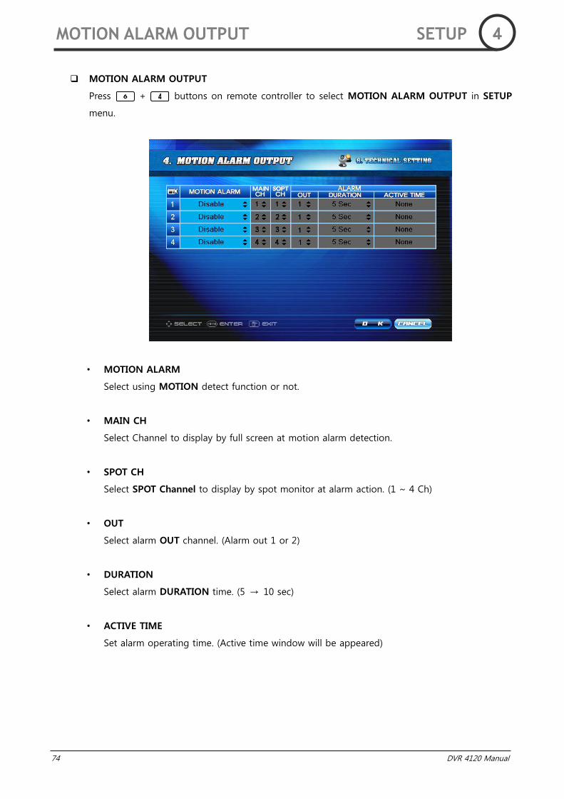
MOTION ALARM OUTPUT
Press + buttons on remote controller to select MOTION ALARM OUTPUT in SETUP
menu.
• MOTION ALARM
Select using MOTION detect function or not.
• MAIN CH
Select Channel to display by full screen at motion alarm detection.
• SPOT CH
Select SPOT Channel to display by spot monitor at alarm action. (1 ~ 4 Ch)
• OUT
Select alarm OUT channel. (Alarm out 1 or 2)
• DURATION
Select alarm DURATION time. (5 → 10 sec)
• ACTIVE TIME
Set alarm operating time. (Active time window will be appeared)
MOTION ALARM OUTPUT SETUP 4
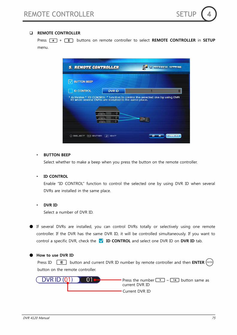
DVR 4120 Manual 75
REMOTE CONTROLLER
Press + buttons on remote controller to select REMOTE CONTROLLER in SETUP
menu.
• BUTTON BEEP
Select whether to make a beep when you press the button on the remote controller.
• ID CONTROL
Enable “ID CONTROL” function to control the selected one by using DVR ID when several
DVRs are installed in the same place.
• DVR ID
Select a number of DVR ID.
If several DVRs are installed, you can control DVRs totally or selectively using one remote
controller. If the DVR has the same DVR ID, it will be controlled simultaneously. If you want to
control a specific DVR, check the ID CONTROL and select one DVR ID on DVR ID tab.
How to use DVR ID
Press ID button and current DVR ID number by remote controller and then ENTER
button on the remote controller.
REMOTE CONTROLLER SETUP 4
Press the number ~ button same as current DVR ID
Current DVR ID
ENTER

76 DVR 4120 Manual
ETC.
Press + buttons on remote controller to select ETC. in SETUP menu.
Alarm(sensor) input type can be set either NO(Normal Open) or NC(Normal Close) in each
channel.
NO(Normal Open) sensor type normally keeps “OFF” state and converts to “ON” state when
sensor is detected.
NC(Normal Close) sensor type normally keeps “ON” state and converts to “OFF” when sensor is
detected.
Alarm output type can also be set by NO(Normal Open) or NC(Normal Close) in each channel.
• ALARM INPUT
Select sensor action way between NO(Normal Open) or NC(Normal Close).
• ALARM OUTPUT
Select alarm action way between NO(Normal Open) or NC(Normal Close).
ETC. SETUP 4
DVR 4120 Manual 77
78 DVR 4120 Manual
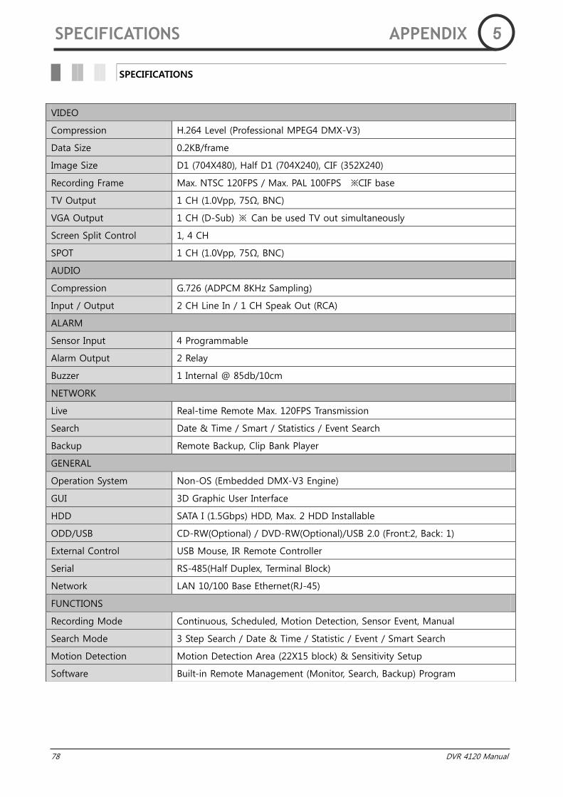
SPECIFICATIONS
VIDEO
Compression H.264 Level (Professional MPEG4 DMX-V3)
Data Size 0.2KB/frame
Image Size D1 (704X480), Half D1 (704X240), CIF (352X240)
Recording Frame Max. NTSC 120FPS / Max. PAL 100FPS ※CIF base
TV Output 1 CH (1.0Vpp, 75Ω, BNC)
VGA Output 1 CH (D-Sub) ※ Can be used TV out simultaneously
Screen Split Control 1, 4 CH
SPOT 1 CH (1.0Vpp, 75Ω, BNC)
AUDIO
Compression G.726 (ADPCM 8KHz Sampling)
Input / Output 2 CH Line In / 1 CH Speak Out (RCA)
ALARM
Sensor Input 4 Programmable
Alarm Output 2 Relay
Buzzer 1 Internal @ 85db/10cm
NETWORK
Live Real-time Remote Max. 120FPS Transmission
Search Date & Time / Smart / Statistics / Event Search
Backup Remote Backup, Clip Bank Player
GENERAL
Operation System Non-OS (Embedded DMX-V3 Engine)
GUI 3D Graphic User Interface
HDD SATA I (1.5Gbps) HDD, Max. 2 HDD Installable
ODD/USB CD-RW(Optional) / DVD-RW(Optional)/USB 2.0 (Front:2, Back: 1)
External Control USB Mouse, IR Remote Controller
Serial RS-485(Half Duplex, Terminal Block)
Network LAN 10/100 Base Ethernet(RJ-45)
FUNCTIONS
Recording Mode Continuous, Scheduled, Motion Detection, Sensor Event, Manual
Search Mode 3 Step Search / Date & Time / Statistic / Event / Smart Search
Motion Detection Motion Detection Area (22X15 block) & Sensitivity Setup
Software Built-in Remote Management (Monitor, Search, Backup) Program
SPECIFICATIONS APPENDIX 5
DVR 4120 Manual 79
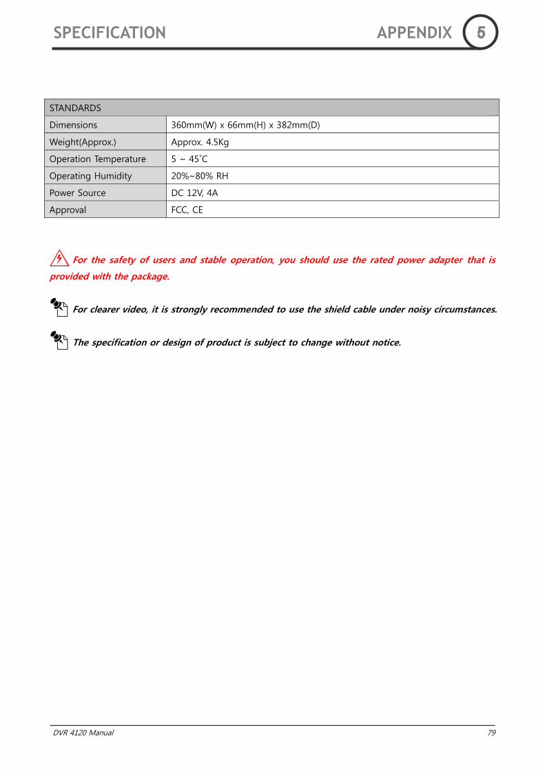
For the safety of users and stable operation, you should use the rated power adapter that is
provided with the package.
For clearer video, it is strongly recommended to use the shield cable under noisy circumstances.
The specification or design of product is subject to change without notice.
STANDARDS
Dimensions 360mm(W) x 66mm(H) x 382mm(D)
Weight(Approx.) Approx. 4.5Kg
Operation Temperature 5 ~ 45˚C
Operating Humidity 20%~80% RH
Power Source DC 12V, 4A
Approval FCC, CE
SPECIFICATION APPENDIX 5
80 DVR 4120 Manual
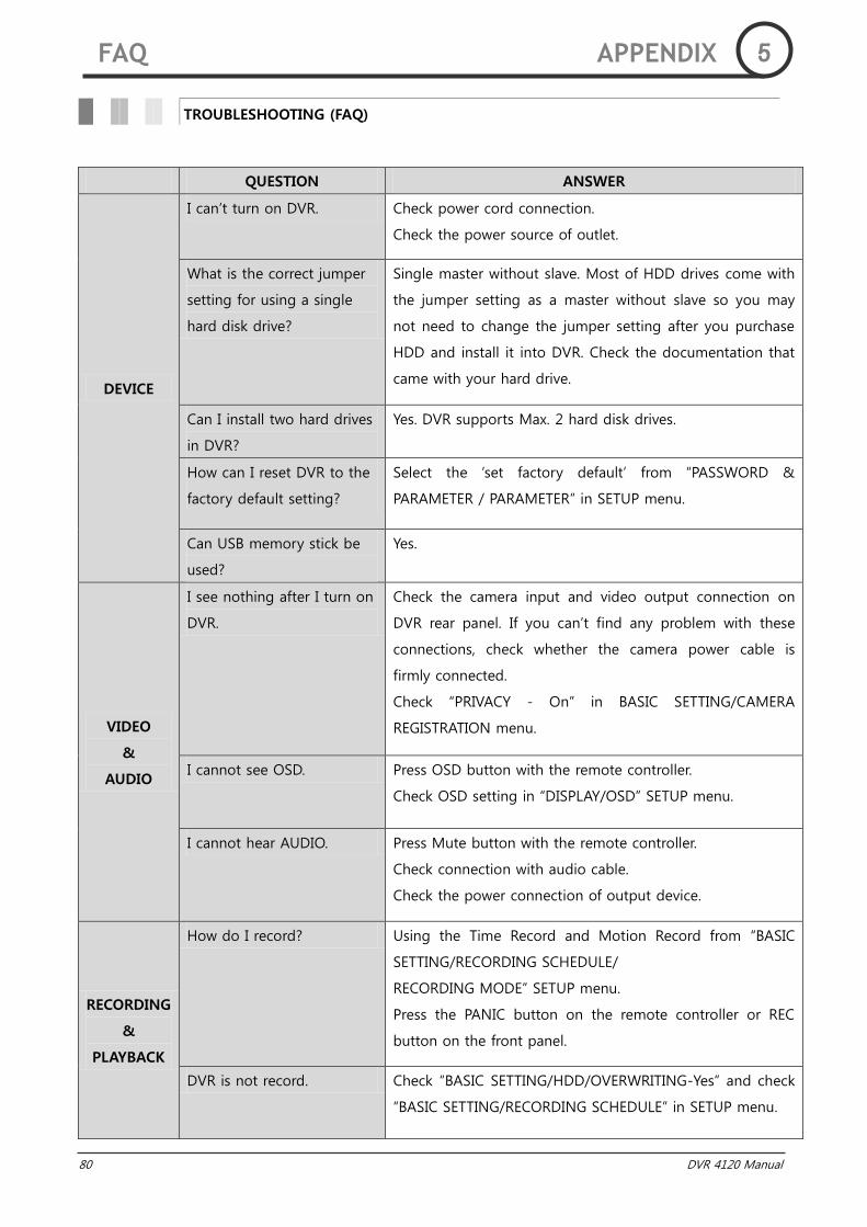
QUESTION ANSWER
DEVICE
I can‟t turn on DVR. Check power cord connection.
Check the power source of outlet.
What is the correct jumper
setting for using a single
hard disk drive?
Single master without slave. Most of HDD drives come with
the jumper setting as a master without slave so you may
not need to change the jumper setting after you purchase
HDD and install it into DVR. Check the documentation that
came with your hard drive.
Can I install two hard drives
in DVR?
Yes. DVR supports Max. 2 hard disk drives.
How can I reset DVR to the
factory default setting?
Select the „set factory default‟ from “PASSWORD &
PARAMETER / PARAMETER” in SETUP menu.
Can USB memory stick be
used?
Yes.
VIDEO
&
AUDIO
I see nothing after I turn on
DVR.
Check the camera input and video output connection on
DVR rear panel. If you can‟t find any problem with these
connections, check whether the camera power cable is
firmly connected.
Check “PRIVACY - On” in BASIC SETTING/CAMERA
REGISTRATION menu.
I cannot see OSD. Press OSD button with the remote controller.
Check OSD setting in “DISPLAY/OSD” SETUP menu.
I cannot hear AUDIO. Press Mute button with the remote controller.
Check connection with audio cable.
Check the power connection of output device.
RECORDING
&
PLAYBACK
How do I record? Using the Time Record and Motion Record from “BASIC
SETTING/RECORDING SCHEDULE/
RECORDING MODE” SETUP menu.
Press the PANIC button on the remote controller or REC
button on the front panel.
DVR is not record. Check “BASIC SETTING/HDD/OVERWRITING-Yes” and check
“BASIC SETTING/RECORDING SCHEDULE” in SETUP menu.
TROUBLESHOOTING (FAQ)
FAQ APPENDIX 5

DVR 4120 Manual 81
RECORDING
&
PLAYBACK
Is it possible to backup the
wanted section of video
during the playback?
Yes, select starting and ending time, then use the Backup
to save.
Can I record everything
24hours 7days a week
without stopping?
Yes. On „Recording Schedule‟ on the SETUP menu, select
“Time Lapse” and “Every”.
DVR stopped for recording. Check HDD space.
Set „OVERWRITING-On‟ in “BASIC SETTING/HDD” SETUP
menu.
ETC.
How can I erase all data on
the hard disk drive?
Select „FORMAT‟ option on the “BASIC SETTING / HDD” in
SETUP menu.
I hear beeping continuously
at DVR.
Check connection between camera and DVR.
Check the power connection of camera.
Check if HDD gets full.
Remote controller is not
work.
Confirm and change whether battery of remote controller
was consumed.
Set by equal ID in case DVR and remote controller ID do
not fit each other.
For more detail. See “TECHNICAL SETTING / REMOTE
CONTROLLER” in SETUP manual.
What does that Event
mean?
That means Motion, Log-in, Video-loss event activity.
FAQ APPENDIX 5

82 DVR 4120 Manual
Tech support code is function that current sets compare with default sets. So user will find easily error
to DVR. It presses button of the remote controller at Live mode, tech support code will be
displayed on screen. Tech support code displays on screen for 10 seconds.
NNoo CCooddee((RReedd)) MMeessssaaggee((BBllaacckk)) MMeeaanniinngg ooff CCooddee
1 TIME11 TIME11 :1211-1400 DVR is not record from 12:11 until the 14:00.
2 FR11 FR11: 1.4 Set „0‟ frame on 1, 4 channels.
3 MA12 MA12: 2, 3 Motion area sets „None‟ on 2, 3 channels.
4 VL12 VL12: 2 Set „Video Loss beep‟ on 2 channels.
5 PRI12 PRI12: 2 Set „Privacy‟ on 2 channels.
6 HDDO14 HDDO14 HDD Overwriting sets „No‟
7 DHCP21 DHCP21 DHCP IP cannot be allocated a IP.
8 PORT22 PORT22: 81 Port sets „81‟.
9 DDNS22 DDNS22 DDNS ID is not checked.
10 UPDATE62 UPDATE62 Update server is not same as default server.
11 ID CTR63 ID CTR63 Select the ID CONTROL.
12 OSD32 OSD32 OSD is set with all off.
13 ADJ31 ADJ31: 1,7 Adjustment is set over 10 from default settings.
TECH SUPPORT CODE
APPENDIX 5
TIME11: 1211 – 1400
FR11: 1. 4
MA12: 2. 3

DVR 4120 Manual 83
MEMO 6

84 DVR 4120 Manual