Embed Size (px)
Citation preview

DF8 PLUS SERIES¼ to 5 HP
Full Wave Regenerative ReversingSCR Speed Controls
for DC Motors
CAUTIONEquipment is at possibly lethal AC line voltage when AC power isconnected. Pressing the STOP pushbutton does not remove AC linevoltage. Both phases must be disconnected before it is safe to touchmotor terminals or control equipment parts.
Saftronics, Inc.5580 Enterprise Pkwy., Ft. Myers, Fl 33905Telephone: (941) 693-7200Fax: (941) 693-2431
SAFTRONICS
P/N X010034 REV:5
efesotomasyon.com - Control Techniques,emerson,saftronics -ac drive-servo motor

DF8 PLUSINSTRUCTION MANUAL
CONTENTS
Section 1.0: Description1.1 Overview ...................................................................................................... 11.2 Standard Features ......................................................................................... 2
Section 2.0: Specifications2.1 Electrical....................................................................................................... 22.2 Electrical protection ..................................................................................... 32.3 Mechanical ................................................................................................... 32.4 Adjustments ................................................................................................. 42.5 Jumper selections ......................................................................................... 5
Section 3.0: Receiving & Installation3.1 Installation ................................................................................................... 63.2 Derating data ................................................................................................ 63.3 Wiring........................................................................................................... 6
Section 4.0: Startup4.1 Inspection .................................................................................................... 74.2 Pre-start adjustments ................................................................................... 74.3 Starting......................................................................................................... 7
Section 5.0: Troubleshooting..................................................................................................................... 8
Section 6.0: Wiring diagrams6.1 DF8P-10 & DF8P-15 .................................................................................. 96.2 DF8P-25 ..................................................................................................... 106.3 Typical torque control connection ............................................................. 116.4 Motor connections ..................................................................................... 12
Section 7.0: Dimensional outlines7.1 DF8P-10 & DF8P-15 Chassis ................................................................... 137.2 DF8P-25 Chassis ....................................................................................... 147.3 NEMA 1 Enclosed with operators ............................................................ 15
Section 8.0: Spare parts................................................................................................................... 16
Section 9.0: Warranty................................................................................................................... 17
Eff Date: 25Aug97
efesotomasyon.com - Control Techniques,emerson,saftronics -ac drive-servo motor

SAFTRONICS
1
1.0 DESCRIPTION1.1 Overview DF8 "Plus" series fully regenerative four quadrant thyristor control-
lers are designed to control the speed of wound field or permanentmagnet dc motors from ¼ to 5 hp. These drives can also be modifiedto become torque control regulators. DF8 "Plus" drives are suppliedin either chassis or Nema 1 enclosed formats.
••••• Control block diagram
••••• Four quadrant operation
Note:
Arrows same direction
Motoring
Arrows opposite
Braking
Motor rotation
Torque
efesotomasyon.com - Control Techniques,emerson,saftronics -ac drive-servo motor

SAFTRONICS
2
••••• Isolated current feedbackAC current transformers sense current in each bridge.
••••• Impedance-isolated armature voltage feedbackHigh impedance resistive voltage divider network used for arma-ture voltage feedback.
••••• Tachogenerator feedback50 volt/1000 rpm tachometers may only be used for speedfeedback.
••••• Dual AC line voltage120 or 240 vac line voltages are plug selectable.
••••• Dual field voltage100/50 or 200/100 volt field supplies for 120 or 240 ac linevoltages.
••••• Matched +12V and -12V reference supply••••• Regenerative braking to zero speed with signal contact
output••••• LED indication
Power on (DS8 red)Forward speed reference (DS5 green)Reverse speed reference (DS4 red)Forward amplifier output (DS7 green)Reverse amplifier output (DS6 red)Run relay energized (DS2 red)Inhibit (DS3 red)Zero speed (DS1 red)
1.2 Standard Features
••••• PowerSingle phase 120 or 240 vac, 50/60 Hz., (±10%).
••••• Speed range30:1 with armature feedback, 50:1 with tachometer feedback.
••••• Load regulation±3% with armature voltage, (±10% line voltage change).
••••• Acceleration/DecelerationAdjustable: 0.1-30 seconds from 0 to full speed.
••••• Temperature range32°F - 104°F (0-40°C).
••••• Altitude2000 feet (600m) maximum without derating.
••••• Regenerative brakingUpon application of a stop signal the drive will regenerativelybrake and stop at zero speed. This feature depends on the settingof jumper P1 (see page 5).
2.1 Electical2.0 SPECIFICATIONS
efesotomasyon.com - Control Techniques,emerson,saftronics -ac drive-servo motor

SAFTRONICS
3
••••• Rectifier configurationThe DF8 "Plus" employs two single phase, full-wave, fullycontrolled, (4 SCR) bridges to allow extremely rapid motorarmature reversing.
••••• HP & Current rating
M O D E LH P A M P S
120 VAC 240 VAC I N P U T O U T P U T
DF8P-10 1 2 1 8 1 0
DF8P-15 1.5 3 2 5 1 5
DF8P-25 2.5 5 3 7 2 5
••••• Voltage rating
INPUTOUTPUT VDC
ARMATURE FIELD
120 VAC (J6) 90090 100/50
240 VAC (J5) 1800180 200/100
••••• Short circuit ratingSuitable for use on a circuit capable of delivering not more than5000 rms symmetrical amperes, 240 V maximum.
••••• FusingOne fast-acting fuse in each AC leg.
••••• Current limitAdjustable current limit circuit for each bridge.
••••• Surge suppressionMOV surge suppressor.
For dimensional information see pages 13 & 14.
2.1 Electrical cont'd
2.3 Mechanical
2.2 Electrical Protection
efesotomasyon.com - Control Techniques,emerson,saftronics -ac drive-servo motor
SAFTRONICS
4
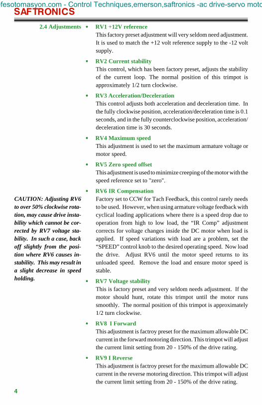
••••• RV1 +12V referenceThis factory preset adjustment will very seldom need adjustment.It is used to match the +12 volt reference supply to the -12 voltsupply.
••••• RV2 Current stabilityThis control, which has been factory preset, adjusts the stabilityof the current loop. The normal position of this trimpot isapproximately 1/2 turn clockwise.
••••• RV3 Acceleration/DecelerationThis control adjusts both acceleration and deceleration time. Inthe fully clockwise position, acceleration/deceleration time is 0.1seconds, and in the fully counterclockwise position, acceleration/deceleration time is 30 seconds.
••••• RV4 Maximum speedThis adjustment is used to set the maximum armature voltage ormotor speed.
••••• RV5 Zero speed offsetThis adjustment is used to minimize creeping of the motor with thespeed reference set to "zero".
••••• RV6 IR CompensationFactory set to CCW for Tach Feedback, this control rarely needsto be used. However, when using armature voltage feedback withcyclical loading applications where there is a speed drop due tooperation from high to low load, the “IR Comp” adjustmentcorrects for voltage changes inside the DC motor when load isapplied. If speed variations with load are a problem, set the“SPEED” control knob to the desired operating speed. Now loadthe drive. Adjust RV6 until the motor speed returns to itsunloaded speed. Remove the load and ensure motor speed isstable.
••••• RV7 Voltage stabilityThis is factory preset and very seldom needs adjustment. If themotor should hunt, rotate this trimpot until the motor runssmoothly. The normal position of this trimpot is approximately1/2 turn clockwise.
••••• RV8 I ForwardThis adjustment is factroy preset for the maximum allowable DCcurrent in the forward motoring direction. This trimpot will adjustthe current limit setting from 20 - 150% of the drive rating.
••••• RV9 I ReverseThis adjustment is factroy preset for the maximum allowable DCcurrent in the reverse motoring direction. This trimpot will adjustthe current limit setting from 20 - 150% of the drive rating.
2.4 Adjustments
CAUTION: Adjusting RV6to over 50% clockwise rota-tion, may cause drive insta-bility which cannot be cor-rected by RV7 voltage sta-bility. In such a case, backoff slightly from the posi-tion where RV6 causes in-stability. This may result ina slight decrease in speedholding.
efesotomasyon.com - Control Techniques,emerson,saftronics -ac drive-servo motor

SAFTRONICS
5
2.5 Jumper Selections
AUX SPD
Note: If P1 is in the “IN”position, the drive will stillregenerate when the speedreference command is re-duced.
••••• J5 & J6 AC Input selectionThis jumper is used to select the correct AC line input voltage.
J5: 240 vac (factory default)J6: 120 vac
••••• P1 Stopping modeMotor coasts to zero speed on stop command. ConnectP1 on the AA1152 control card to the “IN” position.
Motor regenerates to zero speed on stop command.("OUT" position, factory default).
••••• JP1 Programmable inputThis jumper is used to select either tachometer feedback 50v/1000rpm) or auxiliary speed reference input. The auxiliary speed inputwill allow the user to trim (±) the main speed reference. Theauxiliary input is not affected by the accel/decel circuit.
Auxiliary speed input
With JP1 in the "AUX SPD" position, the drive is configured toaccept an auxiliary speed command. The speed input willthen be accepted on input terminals J1-1 and J1-2.
Tachometer feedback
With JP1 in the "TACH" position, the drive is configuredto accept a 50v/1000 rpm analog DC tachometer only.The tachometer input will be accepted on input terminalsJ1-1 and J1-2.
Locate jumpers E1 and E2 above the control transformerT1. These jumpers will be connected to a black wireterminal. Separate the plug from the socket for tachom-
eter feedback.
To set the drive back to armature feedback, insert the plug into thesocket and remove the tach wires from terminals J1-1 and J1-2.
IN
OUT
Caution: This drive can notbe configured to accept ta-chometer feedback and anauxiliary speed commandtogether.
TACH
efesotomasyon.com - Control Techniques,emerson,saftronics -ac drive-servo motor

SAFTRONICS
6
3.0 RECEIVING & INSTALLATION3.1 Installation The cabinet containing the DF8 Plus must be installed in an area where
the following conditions exist:Ambient temperature does not exceed 40ºC (104ºF).Ambient temperature is not less than 10ºC (50ºF).Altitude above sea level is 2000 feet (600m) or less.Ambient air is reasonably clean, dry and free of flammable orcombustible vapors, steam, or corrosive gases, etc.
The cabinet must be installed away from any heat source, and aminimum of 1 foot (30.48 cm) is required around the air inlet andoutlet, on ventilated units.
The DF8 Plus has been designed for 50ºC maximum inside theenclosure.
When the unit is installed in poor environmental conditions, it must bederated as follows:
1.5% per Cº above 40ºC, or 0.75% per Fº above 104ºF.15% per 1000 feet (300m) above 2000 feet (600m).
The DF8 Plus is to be connected according to the NEC and any otherapplicable Electrical Codes in the customer's area. The chassis mustbe bonded to earth ground.
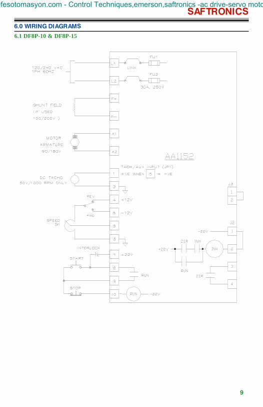
Section 6 pages 8, 9, and 10 show typical connections for speedcontrolled wound field motors. For permanent magnet motors, therewill be no connections to F+ and F-.
See page 11 for typical torque control connections.
Note: For motor field connections of 100/50 or 200/100, refer to page12.
3.2 Derating Data
3.3 Wiring
efesotomasyon.com - Control Techniques,emerson,saftronics -ac drive-servo motor
SAFTRONICS
7
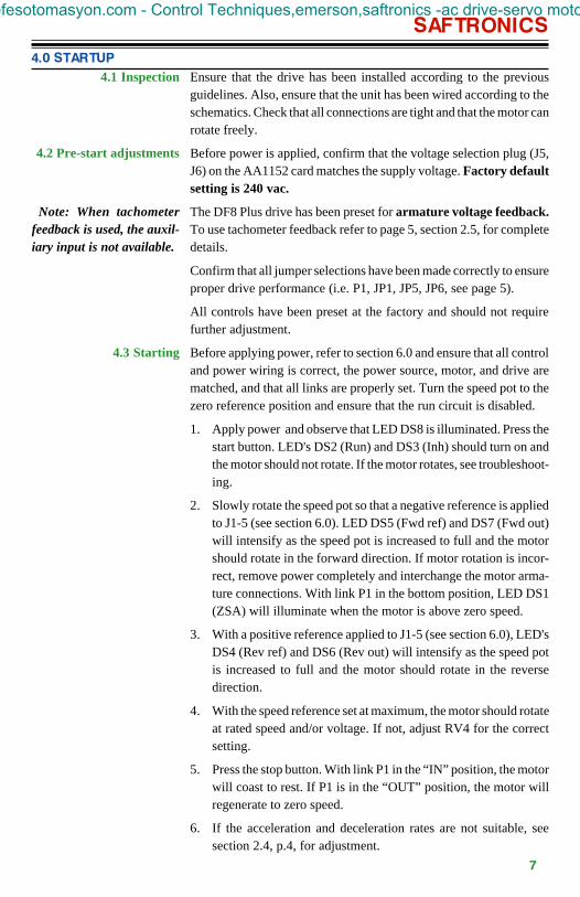
4.0 STARTUP4.1 Inspection Ensure that the drive has been installed according to the previous
guidelines. Also, ensure that the unit has been wired according to theschematics. Check that all connections are tight and that the motor canrotate freely.
Before power is applied, confirm that the voltage selection plug (J5,J6) on the AA1152 card matches the supply voltage. Factory defaultsetting is 240 vac.
The DF8 Plus drive has been preset for armature voltage feedback.To use tachometer feedback refer to page 5, section 2.5, for completedetails.
Confirm that all jumper selections have been made correctly to ensureproper drive performance (i.e. P1, JP1, JP5, JP6, see page 5).
All controls have been preset at the factory and should not requirefurther adjustment.
Before applying power, refer to section 6.0 and ensure that all controland power wiring is correct, the power source, motor, and drive arematched, and that all links are properly set. Turn the speed pot to thezero reference position and ensure that the run circuit is disabled.
1. Apply power and observe that LED DS8 is illuminated. Press thestart button. LED's DS2 (Run) and DS3 (Inh) should turn on andthe motor should not rotate. If the motor rotates, see troubleshoot-ing.
2. Slowly rotate the speed pot so that a negative reference is appliedto J1-5 (see section 6.0). LED DS5 (Fwd ref) and DS7 (Fwd out)will intensify as the speed pot is increased to full and the motorshould rotate in the forward direction. If motor rotation is incor-rect, remove power completely and interchange the motor arma-ture connections. With link P1 in the bottom position, LED DS1(ZSA) will illuminate when the motor is above zero speed.
3. With a positive reference applied to J1-5 (see section 6.0), LED'sDS4 (Rev ref) and DS6 (Rev out) will intensify as the speed potis increased to full and the motor should rotate in the reversedirection.
4. With the speed reference set at maximum, the motor should rotateat rated speed and/or voltage. If not, adjust RV4 for the correctsetting.
5. Press the stop button. With link P1 in the “IN” position, the motorwill coast to rest. If P1 is in the “OUT” position, the motor willregenerate to zero speed.
6. If the acceleration and deceleration rates are not suitable, seesection 2.4, p.4, for adjustment.
4.2 Pre-start adjustments
Note: When tachometerfeedback is used, the auxil-iary input is not available.
4.3 Starting
efesotomasyon.com - Control Techniques,emerson,saftronics -ac drive-servo motor

SAFTRONICS
8
SYMPTOM PROBABLE CAUSE
Motor does not run
- No Run command.
- Speed reference at 0 volts.
- Blown fuses or no AC source.
AC line fuse/fuses blown
- SCR shorted.
- Field diodes shorted (D18).
- Grounded motor armature orfield.
Motor runs at slow speed withthe speed pot set fully cw.
- Max speed set too low.
- Drive in current limit.
- Tach feedback resistorincorrect (if used).
- Bad speed pot.
Motor unstable.
- IR comp turned too high
- Voltage stability setincorrectly.
- Current stability setincorrectly.
- Max speed set too high.
- Fwd/Rev current limits setdifferently.
Motor overspeeds with lowspeed reference
- Max speed set too high.
- Tach input reversed (if used).
- No tach feedback if in tachmode.
Motor drifts at zero speed -Adjust RV5 potentiometer.
5.0 TROUBLESHOOTING
efesotomasyon.com - Control Techniques,emerson,saftronics -ac drive-servo motor
SAFTRONICS
9
6.0 WIRING DIAGRAMS
6.1 DF8P-10 & DF8P-15
efesotomasyon.com - Control Techniques,emerson,saftronics -ac drive-servo motor

SAFTRONICS
10
6.0 WIRING DIAGRAMS CONT'D
6.2 DF8P-25
efesotomasyon.com - Control Techniques,emerson,saftronics -ac drive-servo motor

SAFTRONICS
11
6.0 WIRING DIAGRAMS CONT'D
6.3 6.3 6.3 6.3 6.3 Typical Torque control connection
efesotomasyon.com - Control Techniques,emerson,saftronics -ac drive-servo motor

SAFTRONICS
12
6.0 WIRING DIAGRAMS CONT'D
6.4 6.4 6.4 6.4 6.4 MOTOR CONNECTIONS
efesotomasyon.com - Control Techniques,emerson,saftronics -ac drive-servo motor

SAFTRONICS
13
7.0 DIMENSIONAL OUTLINES
7.1 7.1 7.1 7.1 7.1 DF8P-10 & DF8P-15 CHASSIS
DF8P-10
DF8P-15
efesotomasyon.com - Control Techniques,emerson,saftronics -ac drive-servo motor

SAFTRONICS
14
7.0 DIMENSIONAL OUTLINES CONT'D
7.2 DF8P-25 CHASSIS
efesotomasyon.com - Control Techniques,emerson,saftronics -ac drive-servo motor

SAFTRONICS
15
7.0 DIMENSIONAL OUTLINES CONT'D
7.3 NEMA 1 ENCLOSED WITH OPERATORS
efesotomasyon.com - Control Techniques,emerson,saftronics -ac drive-servo motor
SAFTRONICS
16
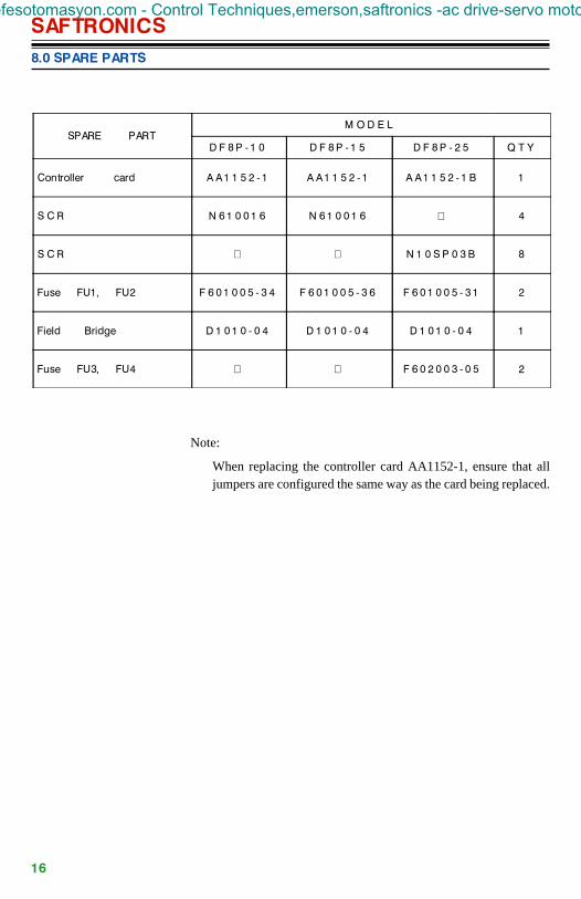
SPARE PARTM O D E L
D F 8 P - 1 0 D F 8 P - 1 5 D F 8 P - 2 5 Q T Y
Controller card A A 1 1 5 2 - 1 A A 1 1 5 2 - 1 A A 1 1 5 2 - 1 B 1
S C R N 6 1 0 0 1 6 N 6 1 0 0 1 6 4
S C R N 1 0 S P 0 3 B 8
Fuse FU1, FU2 F 6 0 1 0 0 5 - 3 4 F 6 0 1 0 0 5 - 3 6 F 6 0 1 0 0 5 - 3 1 2
Field Bridge D 1 0 1 0 - 0 4 D 1 0 1 0 - 0 4 D 1 0 1 0 - 0 4 1
Fuse FU3, FU4 F 6 0 2 0 0 3 - 0 5 2
8.0 SPARE PARTS
Note:
When replacing the controller card AA1152-1, ensure that alljumpers are configured the same way as the card being replaced.
efesotomasyon.com - Control Techniques,emerson,saftronics -ac drive-servo motor

9.0 WARRANTYSaftronics warrants to buyer that products, and any services furnishedhereunder will be free from defects in material, workmanship and title,and will be of the kind and quality specified in the quotation. Theforegoing shall apply only to failures to meet said warranties (excludingany defects in title) which appear within one year from the date ofshipment hereunder, provided, however, that if buyer, in the course ofits regular and usual business, transfers title to or leases such products(including equipment incorporating such products) to a third party,such period shall run until one year from such transfer or lease oreighteen months from shipment by Saftronics whichever occurs first.The warranties and remedies set forth herein are conditioned upon (a)proper storage, installation, use and maintenance, and conformancewith any applicable recommendations of Saftronics and, (b) buyerpromptly notifying Saftronics of any defects and, if required, promptlymaking the product available for correction.
If any products or services fails to meet the foregoing warranties (excepttitle), Saftronics shall thereupon correct any such failure either, at itsoption, (i) by repairing any defective or damaged part or parts of theproducts, or (ii) by making available FOB Saftronics plant or otherpoint of shipment, any necessary repaired or replacement parts. Thepreceding paragraph sets forth the exclusive remedies for claims (exceptas to title) based on defect in or failure of products or services, whetherclaim in contract or tort (including negligence) and however instituted.Upon expiration of the warranty period, all such liability shall termi-nate. The foregoing warranties are exclusive and in lieu of all otherwarranties, whether written, oral, implied or statutory. No impliedstatutory warranty of merchantability or fitness for particular purposeshall apply and Saftronics will not be liable for any consequentialdamage arising from any product defect or failure to deliver on time.Saftronics does not warrant any products or services of others whichbuyer has designated.
17
efesotomasyon.com - Control Techniques,emerson,saftronics -ac drive-servo motor

Saftronics, Inc.5580 Enterprise Pkwy., Ft. Myers, Fl 33905Telephone: (941) 693-7200Fax: (941) 693-2431
efesotomasyon.com - Control Techniques,emerson,saftronics -ac drive-servo motor


![XMWGo vXMWGo vXMWGo v vo ; D:IF o vvo ; D:IF o v · - 2 - k6 :jlsfz sm.56 d\lh, ;]wl 5cm\rjf df8[ v[s gfg]\ 5u,\] ezj]\ 50[ k[p 5|:t]t ;\xmwg df8[ d[\ ez[,f 5u,f\g[ ;tt 5|ti1f s[](https://img.pdfslide.net/doc/110x75/5f0eb7b27e708231d4409864/xmwgo-vxmwgo-vxmwgo-v-vo-dif-o-vvo-dif-o-v-2-k6-jlsfz-sm56-dlh-wl.jpg)

![DF8.ppt [Modo de compatibilidad] · 2013-12-09 · ¿Por qué? Los Emprendimientos de Alto Potencial (EAIs+ EDs) sobre otros tipos de emprendimiento prometen contribuir al desarrollo](https://img.pdfslide.net/doc/110x75/5f1b4a5c414b7934bb1e4433/df8ppt-modo-de-compatibilidad-2013-12-09-por-qu-los-emprendimientos-de.jpg)


![DF8.ppt [Modo de compatibilidad] - camaraguajira.org · ¿Por qué? Los Emprendimientos de Alto Potencial (EAIs+ EDs) sobre otros tipos de emprendimiento prometen contribuir al desarrollo](https://img.pdfslide.net/doc/110x75/5bb26e9709d3f2622d8ca2fb/df8ppt-modo-de-compatibilidad-por-que-los-emprendimientos-de-alto-potencial.jpg)

![;D:IF ooo o - શબ્દપ્રીત · 2014. 4. 27. · 5mtfgf vwif5gdf\ ;]wfzm ,fjjf df8[ vg[ ;\rf,s 5mtfgf xf/f ;\rf,gdf\ vg[ jIJCFZDF\ ;]WFZ6F ,FJJF DF8[ CFY WZ[ T[J]\ ;\XMWG](https://img.pdfslide.net/doc/110x75/60c863ec8ce01136a041b797/dif-ooo-o-aaaaaaaaa-2014-4-27-5mtfgf-vwif5gdf-wfzm.jpg)


![lAGB[TLGF C[T] DF8[ ;ZSFZL 50TZ HDLG VF5JF AFAT[P TFP & q & … · 2010. 4. 5. · sbf ;zsfzl 50tz hdlg algb[tl ljqfis c[t] df8[ u|fg8 szjf afat[ lh](https://img.pdfslide.net/doc/110x75/611a04bc5487840c7668ce32/lagbtlgf-ct-df8-zsfzl-50tz-hdlg-vf5jf-afatp-tfp-q-2010-4-5.jpg)

![Advertisement No. RC/1434/2017 CF.SM8 VMO U]HZFT · Advertisement No. RC/1434/2017 P a g e 6/18 5P lGD6}\S DF8[GL VIMuITF o GLR[ D]HAGL jIlST lGD6}\S DF8[ VIMuI U6FX[ o s!f EFZTLI](https://img.pdfslide.net/doc/110x75/5c02549b09d3f20a538df1b4/advertisement-no-rc14342017-cfsm8-vmo-uhzft-advertisement-no-rc14342017.jpg)