Embed Size (px)
Citation preview

ThemaclassicF24E
Fanned Flue Combination Boiler
G.C.No. 47-047-35
To b e l e f t w i t h t h e u s e r
Instructions for UseInstallation and Servicing
F24E shown
4000124050-2 10.03
Hepworth Heating Ltd., Nottingham Road, Belper, Derbyshire. DE56 1JT
ThemaclassicF18E SB
Fanned Flue System Boiler
G.C. No.41-920-35

24000124050-2
Guarantee Registration
Thank you for installing a new Saunier Duval appliance in your home.Saunier Duval appliances' are manufactured to the very highest standard so we are pleased to offer our customers’ a
Comprehensive Guarantee.This product is guaranteed for 24 months from the date of installation or 30 months from the date of manufacture,
whichever is the shorter, for parts. In addition this product is guaranteed for 12 months from the date of installation or18 months from the date of manufacture, whichever is the shorter, for labour.
The second year of the parts guarantee, from the beginning of the 13th month onwards after installation, is conditionalupon the boiler having been serviced by a CORGI registered gas installer, in accordance
with the manufacturer's recommendations. We strongly recommend regular servicing of your gas appliance, but wherethe condition is not met, any chargeable spare parts or components issued within the applicable guarantee period still
benefit from a 12 month warranty from the date of issue by the manufacturer.
We recommend you complete and return as soon as possible your guarantee registration return literature, supplied inthe document envelope.
If your guarantee registration return literature is missing you can obtain a copy by telephoning
Saunier Duval Service on 00 44 (0)1773 828100.
RECORD YOUR SAUNIER DUVAL APPLIANCE DIRECT BY CALLING
0208 247 9857
Customer Service:Saunier Duval GB GREAT BRITAIN:
Tel. 00 44 (0)1773 828100Fax. 00 44 (0)1773 828070
Hepworth Heating Ltd.,Nottingham Road, Belper, Derbyshire. DE56 1JT
Saunier Duval IE IRELAND:Tel. 00 353 (0)14191919Fax. 00 353 (0)14584806
Hevac,Muirfield Drive
Naas RoadDublin 12
Technical Advice Line:Tel. 00 44 (0)1773 828400
General and Sales enquiries :Tel. 00 44 (0)1773 824141Fax. 00 44 (0)1773 820569(0)

3 4000124050-2
Important Information 4Draining and Filling 5Appliance Introduction 5Appliance Safety Devices 6Maintenance and Servicing 6User Controls and Lighting 7Analogue Programmer F24E only 8Digital Programmer Kit F24E only 8
Technical Data 1 11General Information 2 12Heating System Design 3 13Domestic Hot Water System Design F24E only 4 15Boiler Schematic F24E 5 16Boiler Schematic F18E SB 5a 16Boiler Location, flue and ventilation 6 17Fixing Jig 7 18Piping System Installation 8 19Boiler installation 9 20Horizontal Telescopic Top Flue Installation 10 21Horizontal Top Flue Installation 10a 23Electrical Connection 11 25Commissioning 12 27Changing Gas Type 13 29Bypass Settings 14 29
Routine Cleaning and Inspection 15 30Fault Finding 16 34Wiring Diagram F24E 17 40Wiring Diagram F18E SB 17 41Replacement of Parts 18 42Spare Parts 19 52
CONTENTS DESCRIPTION SECTION PAGE No.
SERVICING
INSTRUCTIONS
INSTALLATION
INSTRUCTIONS
INSTRUCTION
FOR USE
Contents

44000124050-2
Gas safety (Installation and use) RegulationsIn your interests and that of gas safety, it is the law that ALL gasappliances are installed and serviced by a competent personin accordance with the regulations.
Gas leak or faultWARNING: If a gas leak or fault exists or is suspected, turn theboiler off and consult the local gas supply company or yourinstallation/service company.
Testing and CertificationThis boiler is tested and certificated for safety andperformance. It is therefore important that no alteration ismade to the boiler, without permission, in writing, fromHepworth Heating Ltd.
Any alteration not approved by Hepworth Heating Ltd.,could invalidate the certification, boiler warranty and mayalso infringe the current issue of the StatutoryRequirements. The requirements are: The installation of thisboiler must be carried out by a competent person inaccordance with the current rules in force in the countries ofdestination at the time of installation, for Ireland, install inaccordance with I.S.813 "Domestic Gas Installation".Manufacture's instructions supplied must not be taken asoverriding statutory requirements.
CE Mark
This boiler meets the requirements of Statutory InstrumentNo. 3083 The boiler (Efficiency) Regulations, and therefore isdeemed to meet the requirements of Directive 92/42/EEC onthe efficiency requirements for new hot water boilers firedwith liquid or gaseous fuels.
Type test for purposes of Regulation 5 certified by: Notifiedbody 0049.
Product/production certified by: Notified body 0049.
The CE mark on this appliance shows compliance with:
1. Directive 90/396/EEC on the approximation of the laws ofthe Member States relating to appliances burninggaseous fuels.
2. Directive 73/23/EEC on the harmonization of the Laws ofthe Member States relating to the electrical equipmentdesigned for use within certain voltage limits.
3. Directive 89/336/EEC on the approximation of the Laws ofthe Member States relating to electromagnetic compatibility.
Control of Substances Hazardous to HealthThe adhesives and sealants used in this appliance are curedand give no known hazard in this state.
Insulation pads / ceramic fibreThese can cause irritation to skin, eyes and the respiratorytract.If you have a history of skin complaint you may be suscepti-ble to irritation. High dust levels are usual only if the materialis broken.Normal handling should not cause discomfort, but follownormal good hygiene and wash your hands before eating,drinking or going to the lavatory.If you do suffer irritation to the eyes or severe irritation to theskin seek medical attention.The insulation is composed of non-combustible material.
Electrical Supply
WARNING: This boiler must be earthed.
All system components shall be of an approved type and shallbe connected in accordance with the current issue of BS7671and any applicable local regulations.
External wiring must be correctly earthed, polarised and inaccordance with the relevant standards.
In GB this is BS 6891.
In IE this is the current edition of I.S.813 "Domestic gasinstallation".
Connection of the boiler and system controls to the mainssupply must be through a common isolator and must be fusedat 3A, maximum. This method of connection must be by a fuseddouble pole isolating switch, with a minimum contact separationof 3mm on both poles. The switch should be readily accessibleand preferably adjacent to the appliance. It should supply theappliance only and be easily identifiable as so doing.
Alternatively, an unswitched shuttered socket outlet and 3Afused 3 pin plug, both to the current issue of BS1363 may beused provided that they are not used in a room containing a bathor shower.
Wiring to the boiler must be PVC 85oC insulated cable, not lessthan 0.75mm2 (24/0.20mm).
Manual Handling Guidance
During the appliance installation it will be necessary to employcaution and assistance whilst lifting as the appliance exceedsthe recommended weight for a one man lift.
In certain situations it may be required to use a mechanicalhandling aid.
Take care to avoid trip hazards, slippery or wet surfaces.
Heating System Controls
The heating system must be controlled as described in therelevant part of the current issue of :
Building Regulations, approved document L1, and the references:
1) GIL 59, 2000: Central heating system specification (CheSS)and
2) GPG 302, 2001: Controls for domestic central heating systemand hot water. BRECSU.
3) The domestic heating and hot water guide to the buildingregulations 2001.
Thermostatic radiator valves may be installed, however theymust not be fitted in a room where the room thermostat islocated.
Air in the heating system
Persistent air in the heating system may indicate leaks in thesystem or corrosion taking place. Call your Installation/Servicingcompany.
Protection Against Freezing
The appliance has a built in frost protection programme as longas the electricity and gas are left switched on.
This device operates the burner and system pump when thetemperature inside the boiler falls below 60C.
Any other exposed areas of the system should be protected bya separate frost thermostat.
Important Information

5 4000124050-2
Draining and Filling
Appliance Introduction
Diagram 1
BOILER DRAINVALVE
9744
The F24E and F18E SB boilers are wall mounted modulatingboilers with electronic ignition providing central heating andhot water.
The boiler is of the II2H3+ category and is for use with naturalGas (G20) as distributed in the United Kingdom, but can beconverted to use Butane (G30), Propane (G31) with theappropriate kit.
Thema Classic F24E LPG boilers are factory set for useon Butane (G30) and Propane (G31) without requirementfor any additional adjustments.
The boiler has a fan assisted balanced flue which bothdischarges the products of combustion to and draws thecombustion air from the outside of the room.
This boiler is not suitable for outdoor installation.
This boiler may be installed in any room, although particularattention is drawn to the installation of a boiler in a roomcontaining a bath or shower where reference must be made tothe relevant requirements.
Any electrical switch or boiler control utilising mains electricityshould be placed so that it cannot be touched by a personusing the bath or shower.
In GB this is the current I.E.E. WIRING REGULATIONS andBUILDING REGULATIONS.
➜
(a)
(b)
(c)bar
0.5
1
1.5
2
2.5
3
3.5
35
45
55
65
75
Caution: The boiler is installed as part of a sealed systemwhich must only be drained and filled by a competent person.
If the mains electricity and gas are to be turned off for any longperiods during severe weather, it is recommended that thewhole system, including the boiler, refer to diagram 1, shouldbe drained to avoid the risk of freezing. Make sure that, if fitted,the immersion heater in the cylinder is switched off.
If in doubt, consult your servicing company.
F24E Only
• If the boiler loses water: the pressure will be indicated, seediagram 1 (a) and the boiler ON indicator (b) will flash redindicating a fault. Fill the system by the filling device (c) at thebottom of the boiler until the pressure gauge reads 1.0 bar.
A mains inlet pressure of 2.0 bar is required to reach a fillpressure of 1.0 bar.
Reset boiler: refer to diagram 2, turn the On/Off switch to (0),wait for five seconds. Turn the On/Off switch to ( I ) to reset theappliance.
F18E SB Only
• If the boiler loses water: the pressure will be indicated, seediagram 1 (a) and the running lamp (b) will flash red indicatinga fault. Fill the system with the external filling device until thepressure gauge reads 1.0 bar.
Reset boiler: refer to diagram 2, turn the On/Off switch to (0),wait for five seconds. Turn the On/Off switch to ( I ) to reset theappliance.
• Warning: Take care not to overfill the boiler. At a pressure of2.5 bar or above indicating over pressure, the boiler ONindicator (b) will flash red indicating a fault. The pressure mustbe reduced to 1.0 bar by opening the drain valve, refer todiagram 1. If the fault continues call the relevant Servicing
organisation or Saunier Duval Service using the telephonenumber on the inside front cover of this literature.
In IE reference should be made to the current edition of I.S.813"Domestic Gas Installations" and the current ETCI rules.
The central heating and domestic hot water (F24E only)temperatures are user adjustable.
F24E Only. Domestic hot water demand always has priorityover heating demand.
The boiler is designed for use as part of a sealed water centralheating system with fully pumped circulation. The pump,expansion vessel and associated safety devices are all fittedwithin the boiler.
The boiler can be installed against either an external wall or onan adjacent inside wall, that is, the flue system will pass directlyto the rear or to either side to the terminal fitted on the outsidewall face.
These instructions should be carefully followed for the safe andeconomical use of your boiler. The 'User Controls and Lighting'section describes how to safely use the boiler.
Note: The boiler serial number is marked on the data labelattached to the rear of the control box.
Accessories
A range of accessories are available.
For further information contact your supplier.

64000124050-2
Appliance Safety Devices
Maintenance and Servicing
Air flow rate safety device
If the flue is obstructed, the built in safety system will turn theboiler OFF, the fan will continue to run. The boiler will be readyto operate when the fault has been cleared.
Overheating safety
In the event of the boiler overheating the safety devices willcause a safety shutdown. If this happens, call your Installation/Servicing company.
Electrical supply failure
The boiler will not operate without an electrical supply. Normaloperation of the boiler should resume when the electricalsupply is restored.
Reset any central heating system controls, to resume normaloperation.
If the boiler does not resume normal operation turn the mainsreset switch off and on. If the boiler does not resume normaloperation it is advisable to consult your installation / servicingcompany.
Cleaning
WARNING: This appliance contains metal parts (components)and care should be taken when handling and cleaning withparticular regard to edges of sheet metal parts to avoid anypossibility of personal injury.
The boiler casing can be cleaned with a damp cloth, followedby a dry cloth to polish.
Do not use abrasive or solvent cleaners.
Maintenance and ServicingTo ensure the continued efficient and safe operation of theappliance it is recommended that it is checked and serviced asnecessary at regular intervals, but in general once a year shouldbe enough, refer to guarantee registration on the inside frontcover of this literature.
If this appliance is installed in a rented property there is a dutyof care imposed on the owner of the property by the currentissue of the Gas Safety (Installation and Use) Regulations,Section 35.
Servicing/maintenance should be carried out by a competentperson in accordance with the rules in force in the countries ofdestination.
To obtain service, please call the relevant service organisationor Saunier Duval Service using the telephone number on theinside front cover of this literature.
Please be advised that the ‘Benchmark’ logbook should becompleted by the engineer on completion of commissioningand servicing.
All CORGI Registered Installers carry a CORGI ID card, andhave a registration number. Both should be recorded in yourbenchmark Logbook. You can check your installer is CORGIregistered by calling CORGI direct on: 00 44 (0) 1256 372300.
Spare Parts
REMEMBER, When replacing a part on this appliance, use onlyspare parts that you can be assured conform to the safety andperformance specification that we require. Do not usereconditioned or copy parts that have not been clearly authorisedby Hepworth Heating Ltd.
If a part or advice is required contact the relevant serviceorganisation or Heatcall using the telephone number on theinside front cover of this booklet.
Please quote the name of the appliance, this infomation will beon the name badge on the front of the appliance.
Frost protection
The appliance has a built in frost protection device thatprotects the boiler from freezing. With the gas and electricsupplies ON and irrespective of any room thermostat setting,the frost protection device will light the boiler when thetemperature of the boiler water falls below 6°C.
When the temperature reaches 16°C, the boiler stops.
Any other exposed areas of the system should be protected bya separate frost thermostat.
Heating safety valve
CAUTION: A heating safety valve with a discharge pipe is fittedto this boiler.
The valve MUST NOT BE TOUCHED except by a competantperson. If the valve discharges at any time, switch the boiler offand isolate it from the electrical supply. Contact your installation/service company.

7 4000124050-2
User Controls and Lighting
1188
0
1. Lighting the boiler :
Make sure that:• The boiler is connected to the electrical supply.• The gas service cock is open.• The room thermostat is calling for heat (if fitted).
• Turn the On/Off switch to ON ( I )
• The boiler ON indicator will illuminate green.
2. Stop the boiler :
• Turn the On/Off switch to OFF ( 0 ) theelectrical supply is OFF.
1
2
3
4
5
6
3. Domestic hot water adjustment
(F24E Only) :
• Position ( 0 ): Domestic hot waterOFF• Position ( I ) and ECO: Domestichot water between approx. 38˚Cand 50˚C• ECO: Maximum recommendedfor constant use• Between ECO and maxi:Occasional use for water aboveapprox. 50˚C
4. Heating temperature adjustment :• Winter: Set the control knobbetween 1 and 5 (Heating ON)• Summer: Set the control knob
to (Heating OFF)
1
On/Offswitch
Pressure gauge (bar)and temperature
gauge (°C)
Boiler ON indicator(fault indicated bylight flashing red)
Programmer(F24E Only).
Central heating temperature selectorminimum setting (approx. 38˚C) up tomaximum setting (approx. 73°C).
Domestic hot water temperature selector (F24E Only)minimum setting approx. 38˚C up to maximum setting 60˚C.
The ECO setting is ideally suited for all the requirements of normal family use(showers, washing up etc.). The maximum setting should be reserved for occasional usewhen very hot water is required.
Diagram 2
5. If a fault occurs (indicated by
red flashing light) :• Reset boiler: Turn the On/Off switch to ( 0 ),wait for five seconds. Turn the On/Off switch to (I)the boiler is reset. If the fault continues call yourInstallation/Servicing company or Saunier DuvalService using the telephone number on the insidefront cover of this literature.
1
5
3
2
6. Pressure gauge:• The boiler pressure gauge will show a readingbetween 1.0 and 1.5 bar.Refer to Section Draining and Filling if required.
4
5

84000124050-2
Programmer Instructions for Use
Analogue Programmer (F24E Only)Part No. A20086. Fitted as standard.Setting the time, see diagram 3• Rotate the dial clockwise, by hand, until the indicator arrowis pointing to the current time.Note: The time is set in 24 hour format.Setting the programme “on and off” times, see diagram 3• Select the on times by pushing the black tappets to theoutside.• Select the off times by pushing the black tappets to theinside.To override or advance the programmerThe clock has a manual on/off switch which operates asfollows:Upper position I : Heating on continuously
Middle position : Heating on timed
Lower position 0 : Heating off
Digital Programmer Kit. (F24E Only)Part No. A20087. Not fitted as standard.KEYPAD DESCRIPTIONSee diagram 4 for position of keypads as described below,
Time/Automatic Run Mode selectionProg. Programme selectionRes.* Reset clears all settings
ON/OFF selector in Prog. Mode, Manual Override selector in Run Mode
±1h* Summer/Winter time settingh Sets the Hour (12: - - AM)m Sets the Minute (- -: 01 AM)Day Sets Day(s) for time and programmes
*Recessed keys; use a pen point to press
1146
0
Diagram 3
To override or advance the programmer
BLACK TAPPETS
INDICATORARROW
OFFTIMES
ON TIMES
Diagram 4
LCD Display
The LCD incorporates a number of different elements to displayvarious data and information.
Programmes
The Digital Programmer will accept up to 20 events
Each event consists of:
1. An ON or OFF command
2. Time of day (Hour and Minute)
3. Single day or multiple days
An event is required for each ON and OFF.

9 4000124050-2
Programmer Instructions for Use
NOTE: MULTIPLE ON OR OFF EVENTS MAY BEPROGRAMMED, SEE EXAMPLE.
BEFORE PROCEEDING WITH SETTING THE TIME ANDPROGRAMMING THE UNIT, PRESS THE RESET KEY TOCLEAR ALL DATA FROM THE MEMORY.
Selecting AM/PM or 24 Hour Time
After pressing reset, the display may show AM (below). Thenumbered day symbols will be flashing on and off.
If the display does not show AM, it is in 24 hour time. To changeto AM/PM mode, press and hold the h key and press the ±1hkey once. AM will appear in display.
If display is in AM/PM mode and 24 hour time mode is desired,press and hold the h key, press the ±1h key once.
Programming 24 Hour or 7 Day Schedules
It may be helpful to write out the programme schedules beforebeginning.
THE CURRENT TIME OF DAY AND DAY OF WEEK MUST BESET PRIOR TO PROGRAMMING. SEE "SETTING THE TIME"
Example
Event 1: ON at 7:00AM Monday through Saturday
Event 2: OFF at 5:00PM Monday through Friday
Event 3: OFF at 7:00PM Saturday
Three events need to be entered.
Press Prog. key only once. Display shows:
Setting the Time
IF THE h AND m KEYS ARE HELD DOWN LONGER THAN 2SECONDS, THE NUMBERS WILL ADVANCE RAPIDLY.
Press and hold the key during the following:
(If British Summer Time is in effect, press ±1h first)
1. Press h to advance to the current hour(while holding down the key)
2. Press m to advance to the current minute(while holding down the key)
3. Press Day repeatedly to advance to current day(while holding down the key)
Day Key Selections
Press Day Key Display Shows Days
0 times 1 2 3 4 5 6 7 Every Day
1 time 1 2 3 4 5 6 Mon.–Sat.
2 times 1 2 3 4 5 Mon.–Fri.
3 times 6 7 Sat. & Sun.
4 times 1 Monday
5 times 2 Tuesday
6 times 3 Wed.
7 times 4 Thursday
8 times 5 Friday
9 times 6 Saturday
10 times 7 Sunday
NOTE: If the days are flashing, it indicates the day of the weekwas not set when setting the time. The timer cannot beprogrammed unless the day of the week is entered.
Manual GMT/BST Time Changeover
Each year, in the Spring, press ±1h to advance the time anhour. In the Autumn, press ±1h to set back an hour.
Event 1 (ON at 7:00AM Monday through Saturday)
Press key once. ON symbol appears
Press h key to 07AM
Press m key once to 00
Press Day key once 1 2 3 4 5 6 is displayed
Press Prog. key to enter
Event 2 (OFF at 5:00PM Monday through Friday)
Press key twice. OFF symbol appears
Press h key to 05PM
Press m key once to 00
Press Day key two times 1 2 3 4 5 is displayed
Press Prog. key to enter
Event 3 (OFF at 7:00PM Saturday)
Press key twice. OFF symbol appears
Press h key to 07PM
Press m key once to 00
Press Day key 9 times until only 6 is displayed
Press Prog. key to enter
Press key to enter Run Mode
IF AN "ON" TIME WAS PROGRAMMED THAT IS EARLIER INTHE DAY THAN THE CURRENT TIME, PRESS ONCE TOTURN THE TIMER "ON". (IT DOES NOT "LOOK BACK" TODETERMINE IF IT SHOULD BE ON OR OFF AFTERPROGRAMMING).
IF 24 HOUR TIME CONTROL (SAME SCHEDULE EVERY DAYOF THE WEEK) IS DESIRED, IGNORE Day KEY.
If an ON or OFF symbol is not entered, the ON symbol will flash,and programme will not be accepted.

104000124050-2
Programmer Instructions for Use
Event Review
To review the programs at any time, press Prog. key. Events willappear in the order they were entered with repeated presses ofthe Prog. key. After all events have been reviewed, the blankdisplay will appear to allow entering another event. Anotherpress of the Prog. key will display the number of free eventsavailable, such as Fr 16 if 4 events have been entered.
Manual Override
While in the Run Mode, pressing the key once will reversethe current mode; ON to OFF or OFF to ON. The symbolappears in the display to indicate a temporary override.At the next scheduled switching time, automatic controlresumes, eliminating the override.
CONTINUOUS OPERATION: While in the Run Mode, press
the key twice to turn the output to permanently ON.symbol appears in display.
Pressing the key three times will turn the output OFFpermanently. symbol appears in display.
To terminate a continuous override, press the key until appears in the display.
Changing an Event
Select the event to be changed with the Prog. key. A new setof days may be selected with the Day key just as in initialprogramming.
Hours and minutes can be changed with the h and m keys.
Press Prog. or key to store the new programme.
Deleting an Event
To delete only one or a few events: Press Prog. key until thedesired program is displayed.
Press m key to :59 and press once more to blank out.
Press h key to 11PM and press once more to blank out.
Press key, display will flash for several seconds and thenenter the Run Mode. Using the reset key will delete ALL events,the time of day, and day of the week.
Troubleshooting
PROBLEM: Days are flashing, pressing any key does nothing
except key turns output ON and OFF.
SOLUTION: Time of Day and Day of Week have not been set.See "SETTING THE TIME"
This is the condition after a reset. If the timer is found in thiscondition after it has been installed, programmed and operatingfor a while, it may indicate that interference has disrupted themicroprocessor causing a loss of programme information.
A second, but very unlikely cause of loss of programme is apower failure with the backup capacitor low or dead. Check bydisconnecting power and monitoring how long the capacitorkeeps the time of day in the display. Typically, the capacitor willmaintain the time and programmes for 4 days, but not morethan 5 days.
PROBLEM: Time of day was set while holding the keydown, but days are still flashing.
SOLUTION: Current day of week was not set while holdingdown the key. See "SETTING THE TIME"
PROBLEM: It is 10AM and an ON event for 8AM was entered,but the output is not ON. Display shows the and
symbols.
SOLUTION: After programming, the timer does not "look back"to determine if it should be ON. Press the key (temporary
override) to turn the output ON; appears in display.The timer will assume automatic operation at the nextprogrammed event.
PROBLEM: An event for 8AM Monday through Friday wasentered,
but it will not accept it and is flashing.
SOLUTION: The ON or OFF was not entered as partof the program. ON or OFF must be selected.

11 4000124050-2
1 Technical Data
Heat input (max) NET Q 26,94 kW91,200 BTU/H
Heat input (min) NET Q 9,91 kW33,820 BTU/H
Heat output (max) NET P 23,6 kW81,550 BTU/H
Heat output (min) NET P 8,9 kW30,370 BTU/H
Efficiency - Sedbuk D 78,3%Maximum heating temperature 87° CExpansion vessel effective capacity 5 litresExpansion vessel charge pressure 0,5 barMaximum system capacity at 75°C 110 litresSafety valve, maximum service pressure 3 bar
Heating
Heat input (max) NET Q 26,94 kW91,200 BTU/H
Heat input (min) NET Q 9,91 kW33,820 BTU/H
Heat output (max) NET P 23,6 kW81,550 BTU/H
Heat output (min) NET P 8,9 kW30,370 BTU/H
Maximum hot water temperature 60 °CMinimum hot water temperature 38 °CSpecific flow rate (for 35°C temp rise) 9,8 litres/min.Threshold flow rate 1,7 litres/min.Maximum supply pressure 10 barMinimum supply pressure 0,5 bar
Hot water
Electrical supply 230 V ~ 50HzElectrical rating 122 W fused at 3ALevel of protection IPX4DFuse rating 125mA
Electrical
Products outlet diameter 60 mmFresh air inlet diameter 100 mmCombustion products values CO (60 ppm)
CO2 (6,7%)NOx (48ppm)
Combustion
Ø Burner injector 1,2 mmInlet pressure 20 mbarMaxi. Burner pressure 12,2 mbarMini. Burner pressure 2,25 mbarGas rate maximum 2,74 m3/hGas rate minimum 1,16 m3/h
Natural Gas (G20)
Ø Burner injector 0,73 mmInlet pressure 29 mbarMaxi. Burner pressure 23,2 mbarMini. Burner pressure 4,41 mbarGas rate maximum 2,01 kg/hGas rate minimum 0,87 kg/h
Butane Gas (G30)
Ø Burner injector 0,73 mmInlet pressure 37 mbarMaxi. Burner pressure 29,8 mbarMini. Burner pressure 5,4 mbarGas rate maximum 2,01 kg/hGas rate minimum 0,83 kg/h
Propane Gas (G31)
Heat input (max) NET Q 21,9 kW74,722 BTU/H
Heat input (min) NET Q 11 kW37,532 BTU/H
Heat output (max) GROSS P 19,8 kW67,556 BTU/H
Heat output (min) GROSS P 9,2 kW31389 BTU/H
Efficiency - Sedbuk D 78,8%
Maximum heating temperature 87° C
Expansion vessel effective capacity 5 litres
Expansion vessel charge pressure 0,5 bar
Maximum system capacity at 75°C 110 litres
Safety valve, maximum service pressure 3 bar
Ø Burner injector 1,2 mm
Inlet pressure 20 mbar
Maxi. Burner pressure 8,82 mbar
Mini. Burner pressure 2,25 mbar
Gas rate maximum 2,3 m3/h
Heating
Electrical supply 230 V ~ 50HzElectrical rating 122 W fused at 3ALevel of protection IPX4DFuse rating 1,25mA
Natural Gas (G20)
Electrical
Products outlet diameter 60 mm
Fresh air inlet diameter 100 mm
Combustion products values CO (30 ppm)
CO2 (5,9%)
NOx (76 ppm)
Combustion
Ø Burner injector 0,73 mm
Inlet pressure 29 mbar
Maxi. Burner pressure 17,65 mbar
Mini. Burner pressure 4,41 mbar
Gas rate maximum 1,72 kg/h
Gas rate minimum 0,87 kg/h
Butane Gas (G30)
Ø Burner injector 0,73 mm
Inlet pressure 37 mbar
Maxi. Burner pressure 22,52mbar
Mini. Burner pressure 5,4 mbar
Gas rate maximum 1,70 kg/h
Gas rate minimum 0,83 kg/h
Propane Gas (G31)
F24E F18E SB

124000124050-2
1 Technical Data
The F24E and F18E SB are delivered intwo separate packages:• The boiler including hanging bracketcomplete with isolating valves and fittings.• The flue system.
9699
Diagram 1.1
Net lift weight (boiler only)F24E 34 kgF18E SB 32 kg
Gross lift weight(boiler, hanging bracketisolation valves and packaging)F24E 35 kgF18E SB 33 kg
2 General Information
IMPORTANT NOTICE.
Where no British Standards exists, materials and equipmentshould be fit for their purpose and of suitable quality andworkmanship.
Refer to Manual Handling Operations, 1992 regulations.
The installation of this boiler must be carried out by a competentperson in accordance with the rules in force in the countries ofdestination.
Manufacturer’s instructions must not be taken as overridingstatutory requirements.
2.1 Sheet Metal Parts
WARNING: When installing the appliance, care should be takento avoid any possibility of personal injury when handling sheetmetal parts.
2.2 Statutory Requirements
The appliance is suitable only for installation in GB and IE andshould be installed in accordance with the rules in force.
In GB the installation of the boiler MUST be carried out by acompetent person as discribed in the following regulations:
Manufacturer’s instructions, supplied.
The Gas Safety (Installation and Use) Regulations.
The appropriate Building Regulations, either The BuildingRegulations, The Building Regulations (Scotland), The buildingRegulations (Nothern Ireland).
The Water Fittings Regulations or Water Bylaws in Scotland.The Health and Safety at Work Act, Control of SubstancesHazardous to Health (COSHH).
The Current I.E.E. Wiring Regulations.
Where no specific instructions are given, reference should bemade to the relevant British Standard Code of Practice.
In I.E the installation must be carried out by a competent personand installed in accordance with the current edition of I.S. 813
"Domestic Gas Installations", the current Building Regulationsand reference should be made to the current ETCI rules forelectrical installation.
In GB the following Codes of Practice apply:
BS4814, BS5440 Part 1 and 2, BS5449, BS5546 Part 1, BS6700,BS6798, BS6891 and BS7074 Part 1 and 2, BS7478, BS7593,BS7671.
In IE: I.S.813, BS5546, BS5449, BS7074, BS7593.
Manufacturer’s notes must not be taken as overriding statutoryrequirements.
BSI Certification
This boiler certificated to the current issue of EN 483 forperformance and safety.
It is important that no alteration is made to the boiler, withoutpermission, in writing, from Hepworth Heating Ltd.
Any alteration that is not approved by Hepworth Heating Ltd.,could invalidate the warranty and could also infringe the currentissue of the Statutory Requirements.

13 4000124050-2
2.3 Gas Supply
The gas installation must be in accordance with the relevantstandards.
In GB this is BS 6891.
In IE this is the current edition of I.S.813 "Domestic gasinstallation".
The supply from the governed meter must be of adequate sizeto provide a steady inlet working pressure of 20mbar (8in wg) atthe boiler.
Important Notice
If your boiler has been converted to use L.P.G. Propane thefollowing note applies:
Propane cylinders are under pressure and should never bestored or used indoors residentially.
They should only be kept outside.
Under no circumstances should L.P.G. Propane cylinders befitted or stored in basement areas or boiler houses.
On completion, test the gas installation for soundness using thepressure drop method and suitable leak detection fluid, purge inaccordance with the above standard.
50
40
30
20
10
0 500 1000
1
23
4
5
9700
Flow rate through heating system (I/h)(10 kPa = 1 m WG)
1
2
3
4
5
Bypass fully shut
Open 1/4 turn
Open 1/2 turn
Open 1 turn
Open 2 turns Ava
ilab
le p
ress
ure
(kP
a)
Diagram 3.1
3 Heating System Design
2 General Information
The installation of the boiler must comply with the requirementsof the current issue of BS6798, in Ireland, refer also to thecurrent edition of I.S.813"Domestic Gas Installations".
In GB it is necessary to comply with the Water Supply (WaterFittings) Regulations 1999 (for Scotland, the Water Byelaws2000, Scotland).
To comply with the Water Regulations your attention is drawnto: The Water Regulations guide published by the WaterRegulation Advisory Service (WRAS) which gives full details ofthe requirements.
In IE the requirements given in the current edition of I.S.813"Domestic Gas Installations" and the current BuildingRegulations must be followed.
• The F24E and F18E SB are for use with sealed central heatingsystems.
• Heating surfaces may consist of radiators, convectors or fanassisted convectors.
• The safety valve is an integral part of the boiler and it cannotbe adjusted.
• The circulation pump is integral with the boiler.
• Pipe sectional areas shall be determined in accordance withnormal practices, using the output/pressure curve(diagram 3.1). The distribution system shall be calculated inaccordance with the output requirements of the actual system,not the maximum output of the boiler. However, provision shallbe made to ensure sufficient flow so that the temperaturedifference between the flow and return pipes be less than orequal to 20°C. The minimum flow rate is shown in table 1.
• The system can be fitted with a lockable control valve ifnecessary in the main flow or return pipes shown as valve 'A'in diagram 3.2.
• The piping system shall be routed so as to avoid any airpockets and facilitate permanent venting of the installation.Bleed fittings must be provided at every high point of thesystem and on all radiators.
• The total volume of water permitted for the heating systemdepends, amongst other things, on the static head in the coldcondition. The expansion vessel on the boiler is pressurised at0.5 bar and allows a maximum system volume of 110 litres foran average temperature of 75°C and a maximum servicepressure of 3 bar. This pressure setting can be modified atcommissioning stage if the static head differs. An additionalexpansion vessel can be fitted to the system if required, seediagram 3.2.
Guidance on vessel sizing is also given in a current issue of aBS5449 and BS7074 Part 1, for IE refer to the current editionof I.S.813 "Domestic Gas Installations".
• Provision shall be made for a drain valve at the lowest pointof the system.
• Where thermostatic radiator valves are fitted, not all radiatorsmust be fitted with this type of valve, and in particular, wherea room thermostat is installed.
• In the case of an existing installation, it is ESSENTIAL that thesystem is thoroughly flushed prior to installing the new boiler,using a proprietary product from Fernox or Sentinel.
144000124050-2
Controlvalve
Flo
wDrainpoint
Bypassvalve
Domesticwater
Heatingcircuit
Ret
urn
Additionalexpansionvessel(if required)
Hot
wat
er o
ut
Col
d su
pply
in
Drainpoint
Boiler
Filling device
9898
AdditionalBypass valve(if required)*
*
Controlvalve
Flo
wDrainpoint
Bypassvalve
Heatingcircuit
Ret
urn
Additionalexpansionvessel(if required)
Boiler
Diagram 3.2
1015
7
F24E
F18E SB
'A'
AdditionalBypass valve(if required)*
*'A'
TEMPORARYCONNECTION
HOSEUNION
HOSEUNION
SUPPLYPIPE
CONTROLVALVE
CONTROLVALVE
DOUBLECHECKVALVE
BOILER
RETURNFLOW
HEATINGCIRCUIT
DRAINPOINT
SUPPLYPIPE
AIR GAP
TUNDISH
CONTROLVALVE
CONTROLVALVE
TYPE CA BACKFLOWPREVENTION DEVICE
BOILER
RETURNFLOW
HEATINGCIRCUIT
DRAINPOINT
Method 1
Method 2
Diagram 3.3
1159
3
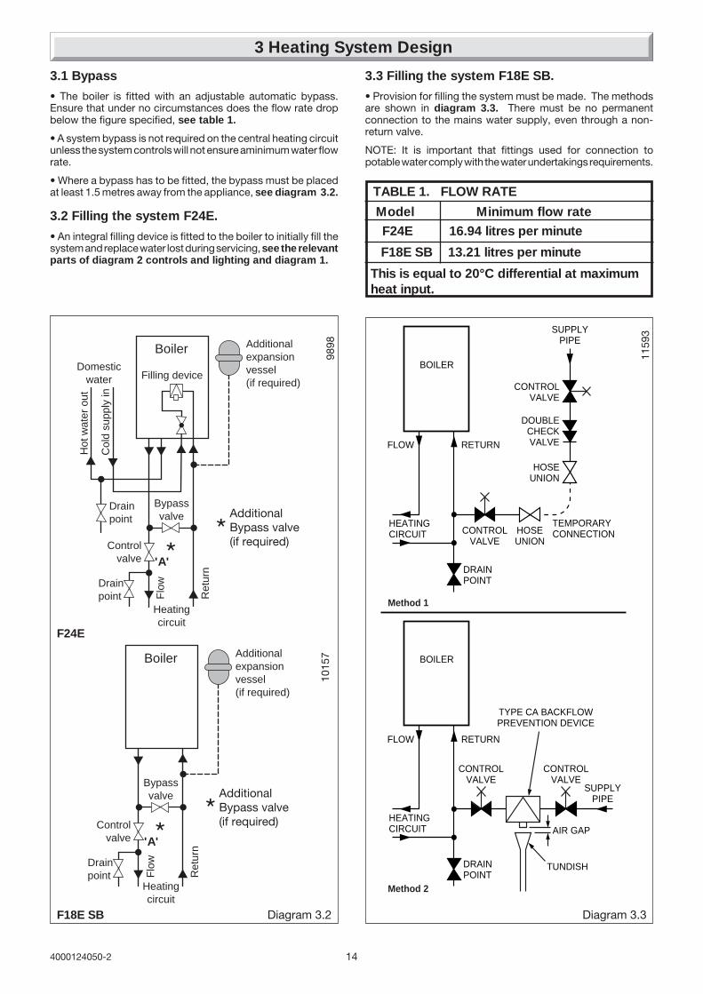
3.1 Bypass
• The boiler is fitted with an adjustable automatic bypass.Ensure that under no circumstances does the flow rate dropbelow the figure specified, see table 1.
• A system bypass is not required on the central heating circuitunless the system controls will not ensure aminimum water flowrate.
• Where a bypass has to be fitted, the bypass must be placedat least 1.5 metres away from the appliance, see diagram 3.2.
3.2 Filling the system F24E.
• An integral filling device is fitted to the boiler to initially fill thesystem and replace water lost during servicing, see the relevantparts of diagram 2 controls and lighting and diagram 1.
3 Heating System Design
TABLE 1. FLOW RATE
Model Minimum flow rate
This is equal to 20°C differential at maximumheat input.
F24E 16.94 litres per minute
F18E SB 13.21 litres per minute
3.3 Filling the system F18E SB.
• Provision for filling the system must be made. The methodsare shown in diagram 3.3. There must be no permanentconnection to the mains water supply, even through a non-return valve.
NOTE: It is important that fittings used for connection topotable water comply with the water undertakings requirements.

15 4000124050-2
General - All domestic hot water circuits, connections, fittingsmust be in accordance with the relevant standards and watersupply regulations.
For GB: Guidance G17 to G24 and recommendation R17 toR24 of the Water Regulation Guide.
For IE: The current edition of I.S.813 "Domestic GasInstallations".
• Copper tubing or plastic Hep20 may be used for the domestichot water system. Unnecessary pressure losses should beavoided.
• Provision shall be made for a drain valve at the lowest pointsof the system.
• The flow restrictor, supplied in the document envelope, mustbe fitted as diagram 7.1, limiting the flow through the boiler toa maximum of 10 litres/min.
• The boiler will operate with a minimum supply pressure of 0.5bar, at a reduced flow rate.
Best operating performance will be obtained from a supplypressure of 1 bar or greater.
4.1 Hard Water Areas
In areas where the water is 'hard', more than 200mg/litre, it isrecommended that a proprietary scale reducer is fitted in thecold water supply to the boiler.
4 Domestic Hot Water System Design. F24E Only

164000124050-2
1 - Fan.2 - Air pressure switch.3 - Heat exchanger.4 - Overheat thermostat.5 - Combustion chamber.6 - Expansion vessel.7 - Flame sense electrode.8 - Burner.9 - Ignition electrode.10 - Pump.11 - Heating thermistor.12 - Ignition unit.13 - By-pass.14 - Gas control valve.15 - Loss of water sensor.16 - Heating filter.17 - Discharge safety valve (3bar).
A - Heating return.B - Heating flow.C - Gas.
Diagram 5a.1
1145
0
FITTED TOREAR OFAPPLIANCE
5a Boiler Schematic F18E SB
1 - Fan.2 - Air pressure switch.3 - Heat exchanger.4 - Overheat thermostat.5 - Combustion chamber.6 - Expansion vessel.7 - Flame sense electrode.8 - Burner.9 - Ignition electrode.10 - Pump.11 - Heating thermistor.12 - Ignition unit.13 - By-pass.14 - Gas control valve.15 - Loss of water sensor.16 - Domestic heat exchanger17 - 3 way valve18 - Domestic water flow sensor19 - Filter cold water inlet20 - Filling system21 - Discharge safety valve (3bar)22 - Drain valve23 - Heating filter
A - Heating returnB - Cold water inletC - Heating flowD - Domestic hot water outletE - Gas
5 Boiler Schematic F24E
9899
FITTED TOREAR OFAPPLIANCE
Diagram 5.1
A B C
17 4000124050-2
6 Boiler Location, Flue and Ventilation
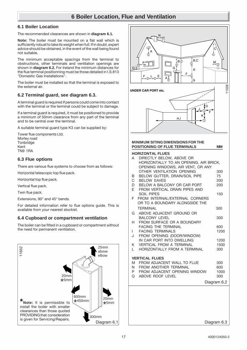
6.1 Boiler Location
The recommended clearances are shown in diagram 6.1.
Note: The boiler must be mounted on a flat wall which issufficiently robust to take its weight when full. If in doubt, expertadvice should be obtained, in the event of the wall being foundnot suitable.
The minimum acceptable spacings from the terminal toobstructions, other terminals and ventilation openings areshown in diagram 6.2. For Ireland the minimum distances forthe flue terminal positionning must be those detailed in I.S.813"Domestic Gas Installations".
The boiler must be installed so that the terminal is exposed tothe external air.
6.2 Terminal guard, see diagram 6.3.
A terminal guard is required if persons could come into contactwith the terminal or the terminal could be subject to damage.
If a terminal guard is required, it must be positioned to providea minimum of 50mm clearance from any part of the terminaland to be central over the terminal.
A suitable terminal guard type K3 can be supplied by:
Tower flue components Ltd.Morley roadTonbridgeKentTN9 1RA
6.3 Flue options
There are various flue systems to choose from as follows:
Horizontal telescopic top flue pack.
Horizontal top flue pack.
Vertical flue pack.
Twin flue pack.
Extensions, 90° and 45° bends.
For detailed information refer to flue options guide. This isavailable from your nearest stockist.
6.4 Cupboard or compartment ventilation
The boiler can be fitted in a cupboard or compartment withoutthe need for permanent ventilation.
Diagram 6.2
MINIMUM SITING DIMENSIONS FOR THEPOSITIONING OF FLUE TERMINALS MM
HORIZONTAL FLUESA DIRECTLY BELOW, ABOVE OR
HORIZONTALLY TO AN OPENING, AIR BRICK,OPENING WINDOWS, AIR VENT, OR ANYOTHER VENTILATION OPENING 300
B BELOW GUTTER, DRAIN/SOIL PIPE 75C BELOW EAVES 200D BELOW A BALCONY OR CAR PORT 200E FROM VERTICAL DRAIN PIPES AND
SOIL PIPES 150F FROM INTERNAL/EXTERNAL CORNERS
OR TO A BOUNDARY ALONGSIDE THETERMINAL 300
G ABOVE ADJACENT GROUND ORBALCONY LEVEL 300
H FROM SURFACE OR A BOUNDARYFACING THE TERMINAL 600
I FACING TERMINALS 1200J FROM OPENING (DOOR/WINDOW)
IN CAR PORT INTO DWELLING 1200K VERTICAL FROM A TERMINAL 1500L HORIZONTALLY FROM A TERMINAL 300
VERTICAL FLUESM FROM ADJACENT WALL TO FLUE 300N FROM ANOTHER TERMINAL 600P FROM ADJACENT OPENING WINDOW 1000Q ABOVE ROOF LEVEL 300
1150
8
Diagram 6.3
*Note: It is permissible toinstall the boiler with smallerclearances than those quotedPROVIDING that considerationis given for Servicing/Repairs.
Diagram 6.1
1165
2
20mm
*5mm
20mm
*5mm
300mm
600mm
*450mm
25mmaboveelbow
184000124050-2
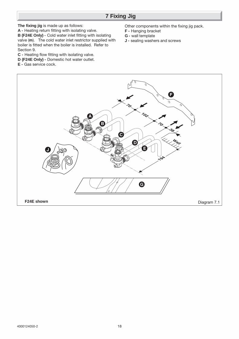
7 Fixing Jig
The fixing jig is made up as follows:A - Heating return fitting with isolating valve.B (F24E Only) - Cold water inlet fitting with isolatingvalve (m). The cold water inlet restrictor supplied withboiler is fitted when the boiler is installed. Refer toSection 9.C - Heating flow fitting with isolating valve.D (F24E Only) - Domestic hot water outlet.E - Gas service cock.
Diagram 7.1
Other components within the fixing jig pack.F - Hanging bracketG - wall templateJ - sealing washers and screws
F24E shown

19 4000124050-2
8.1 Cutting the flue hole
• Remove the wall template, follow the instructions given on thewall template.
• Position the wall template, taking due regard of the minimumclearances for the selected flue application, see diagram 8.1.
• Rear hole cutting
• Mark correct position of Top Rear flue outlet hole fromtemplate, then remove template, before cutting, for use, later.
• Side hole cutting
• Mark the horizontal centre line for the hole on the rear wall.Extend the horizontal centre line to the side wall and mark thevertical centre line of flue hole as shown in diagram 8.1.
IMPORTANT NOTE: When cutting the flue hole and whenextending the flue centre line to a side wall, remember that theflue system must have a fall of about 35mm per metre of fluedownward towards the terminal. There MUST never be adownward incline towards the boiler.
• Making allowance for the slope of the flue, cut hole in externalwall, preferably using a core drill. For installations with internaland external access use a 105mm diameter core drill.
• For installations with internal access only use a 125 mmdiameter core drill.
8.2 Fixing jig, refer to diagram 7.1
• IMPORTANT NOTE: Ensure that the hanging bracket is fittedto a flat and true wall area for correct alignment with the boiler.
Side Flue - Check the horizontal centre line and reposition thetemplate if necessary.
Rear Flue - Reposition the wall template over the hole in wall.
• Mark the securing position holes.
• Check that the hanging bracket is level.
• Drill, plug and secure the bracket to the wall, using suitablescrews (not supplied) for the wall type and capable of supportingthe total weight of the appliance (refer to wall template for fixingpoints).
8.3 Water connection
IMPORTANT NOTE: Do not subject the isolating valves to heatfrom blowlamp, when making connection.
Connect the system pipework to the fixing jig connection pipesand the fixing jig isolating valves, observing the correct flow andreturn as shown in diagram 8.1.
8.4 Gas connection
Gas Safety (Installation and use) Regulations
In your interests and that of gas safety, it is the law that ALL gasappliances are installed and serviced by a competent personin accordance with the above regulations.
• The whole of the gas installation, including the meter, shouldbe inpected, tested for soundness and purged in accordancewith the current issue of BS6891 and in IE the current editionof I.S.813 "Domestic Gas Installations".
8 Piping System Installation
Diagram 8.1F24E shown

204000124050-2
Diagram 9.1
9 Boiler Installation
9.1 Sheet metal parts
WARNING: When installing or servicing this boiler, care shouldbe taken when handling the edges of sheet metal parts to avoidthe possibility of personal injury.
9.2 Installing the boiler
IMPORTANT NOTE: The system must be thoroughly flushedusing a propriety cleanser from Fernox or Sentinel to eliminateany foreign matter and contamination e.g. metal filings, solderparticles, oil, grease etc.
Solvent products could cause damage to the system.
• Remove front panel, unscrew and remove the two retainingscrews from the bottom of the front panel. Remove front panelby lifting up and forward.
• To remove the self adhesive wiring diagram label from thedocument envelope. Fit the self adhesive wiring diagram labelto the inside of the front panel, put front panel in a safe placeto avoid damaging it.
DISCHARGESAFETY VALVEPIPE
KNURLEDUNION NUTfinger tighten only
Diagram 9.2
1008
8
FILLING LOOPEXTENSION
FILLING DEVICE
F24E Only
• If fitted ensure the plastic plugs are removed from waterand gas pipes. NOTE: There will be some spillage of water.
• (F24E Only) Fit the cold water inlet restrictor (supplied in thedocument envelope) into cold water inlet isolating valve, seediagram 7.1.
Important Note. With regards to the manual handlingoperations, 1992 regulations, the following operation exceedsthe recommended weight for one man lift.
• Lift the boiler up and engage boiler onto the hanging bracket,refer to diagram 7.1.
• Fit the boiler connection pipes and washers between the boilerand isolating valves, see diagram 7.1.
9.3 Discharge safety valve (diagram 9.1)
The discharge safety valve pipe and sealing washer suppliedin the connections pack, when fitted to the safety valve, willextend the valve below the boiler. The discharge pipe must beextended using pipe not less than 15 mm o.d. to discharge ina visible position outside the building, facing downwardpreferably over a drain.
IMPORTANT NOTE: To facilitate servicing of the appliance,the discharge pipe MUST ONLY be extended using acompression fitting supplied.
The pipe must have a continuous fall and be routed to aposition so that any discharge of water, possibly boiling orsteam, cannot create any danger to persons, damage toproperty or external electrical components and wiring. Tightenall pipe connection joints.
9.4 Filling loop extension knob F24E Only
The filling loop extension knob is supplied in the dischargesafety valve pipe connection pack. Fit to the filling device on/off knob, this is a push fit, see diagram 9.2.
9.5 Filling loop extension knob F18E SB
The filling loop extension is not required for this boiler, it can bediscarded.

21 4000124050-2
10 Horizontal Telescopic Top Flue Installation
1188
6
The Horizontal Telescopic Top Flue, Kit No.A2004500
Suitable for installations that require a flue length "L" from 430minimum to 660 maximum. If longer flueing is required extensionsand bends are available, see note below.
If the flue length, see diagram 10.2. is less than 430 'L' Do Notcut this flue but use the horizontal top flue 86285.
Note: Additional 1 metre extensions, 90° and 45° bends areavailable. The maximum extended flue is 3.5m. The use of fluebends requires the max extended flue lengths to be reduced by1m. for 90° and 0.5m. for 45°.
10.1 Horizontal Telescopic Top Flue
Kit of parts, refer to diagram 10.1.
10.2 Horizontal telescopic flue system
Rear and side flue lengths and dimensions, seediagram 10.2.
1032
2
The flue kit A2004500 is 660 mm long and comprises: - Telescopic flue assembly ..................................... A - Fixing collar seal .....................................................B - Fixing collar ............................................................. C - Elbow ....................................................................... D - External rubber sealing collar ............................... E - *Gasket .................................................................... F - *Screws 6 off ...........................................................G - *'O' rings .................................................................. H- *Screws 4 off ............................................................ J
* supplied in plastic bag
Diagram 10.1Telescopic Top flue kit
A
B
C
ED
F*H*
H*
Diagram 10.2
70mm
65mm
410 mm
205mm
20mmMin. Clearance
70mm
184mm
65mm
SIDE FLUE
REAR FLUE
L
L
G*
J*
Note :Top of boilercasing notfront panel
Note :Top of boilercasing notfront panel
* refer to diagram 6.1
Drill, Screw andTape (not supplied)

224000124050-2
Diagram 10.4
1187
9
Diagram 10.4
10.3 Installation of telescopic flue assembly
• For flue lengths up to 0.5m fit the restrictor (supplied in thedocument envelope) inside the fan outlet, see diagram 10.3.
• Remove the elbow (D) and the telescopic flue assembly (A)from the flue kit.
• Refer to Step 1. diagram 10.4. Fit the telescopic flueassembly (A) into the prepared hole in the wall. Position theelbow (D) on the boiler, do not secure. Position the telescopicflue assembly (A) as it would be fitted.
• Refer to Step 2. diagram 10.4. Remove the telescopic flueassembly (A) from the prepared hole in the wall, make sure theair duct is extended to its required length. The flue duct at theelbow end must protrude 25mm. Drill ,secure with two screwsand tape to secure the air duct, take care not to drill the innerflue pipe. Fit the fixing collar seal (B) to the telescopic flueassembly (A).
• Refer to Step 3. diagram 10.4. Fit the telescopic flueassembly (A) with the fitted fixing collar seal into the preparedhole in the wall. Remove the backing from the self adhesivegasket (F) and carefully fit gasket to base of flue elbow. Fit the‘O’ rings (H) into the grooves in the flue ducts within the elbow(D). Lubricate the ‘O’ rings with silicone. Fit flue elbow (D) ontoboiler and secure with the four screws (G).
• Refer to Step 4. diagram 10.4. Fit rubber sealing collar (E),into groove at the outer end of the air duct pipe (A). Carefullypull flue duct pipe into the elbow (D). (If the telescopic flue hasbeen pulled apart care must be taken not to damage the ‘O’ ringon the flue duct when re-assembling). Secure with two screws(G). Pull telescopic flue assembly (A) inwards to bring rubbersealing collar hard up against external wall.
• Refer to Step 5. diagram 10.4. Fit the fixing collar (C) usingthe two screws (G).
10 Horizontal Telescopic Top Flue Installation
17mm
90mm
FLUE LENGTH
CL
Outsidewall face
IMPORTANT"BUTT FIT"
GASKET'O' RING
BOILER
2 off
4 off
2 off
ELBOW
BOILER
Fluecentre line
Drill, screw 2 offand tape the Air Duct
25mm minimum Air Duct over lap
FIXINGCOLLAR
SEAL
EXTERNAL RUBBERSEALING COLLAR
FIXINGCOLLAR
25mm
2 off
STEP 1.
STEP 2.
STEP 3.
STEP 4.
STEP 5.
(A)
(A)
(B)
(C)
(D)
(E)
(E)
(F)
(G)
(G)
(H)
(A)
(A)
(A)
(D)
(D)
(D)
(E)
(G)
(G)
1187
4
Diagram 10.3The restrictor must be fittedto the inside of the fan outlet.
RESTRICTORfitted for flue lengthsless than 0.5m

23 4000124050-2
10a Horizontal Top Flue Installation
10a.1 The Horizontal Top flue - kit 86285H
Is suitable for installations that require a max. flue length "L" of740mm.
If a shorter flue length is required, the flue can be cut to a min.length"L" of 260mm rear or 300mm side. See diagram 10a.2 formin. flue lengths.
Note: Additional 1 metre extensions, 90° and 45° bends areavailable. The maximum extended flue is 3.5m. The use of fluebends requires the maximum extended flue lengths to bereduced by 1m. for 90° and 0.5m. for 45°.
10a.2 Flue systems rear and side, refer todiagram 10a.1.
10a.3 Flue cutting, refer to diagram 10a.2.
Important: Do not leave any burrs or sharp edges on the cutends of the pipes.
1188
6
Diagram 10a.2
70mm
65mm
410 mm
205mm
20mmMin. Clearance
70mm
184mm
65mm
SIDE FLUE
REAR FLUE
L
L
Note :Top of boilercasing notfront panel
Note :Top of boilercasing notfront panel
* refer to diagram 6.1
1164
6
B
CJ
IH
F
G
A
D
The flue kit 86285 comprises: - Air duct pipe .......................................................... A - Flue duct pipe ........................................................B - Elbow....................................................................... C - Fixing collar seal .................................................... D - Fixing collar .............................................................. E - External rubber sealing collar ............................... F - Internal flange ....................................................... G - Gasket ..................................................................... H - Screws ....................................................................... I - 'O' rings ..................................................................... J
Diagram 10a.1
E
Horizontal Top flue kit

244000124050-2
10a.4 Installation of horizontal top flueassembly
Important: If the flue has been cut, ensure that there are noburrs that could damage the ‘O’ ring.
• For flue systems less than 0,5 m long, fit the flue restrictor (a)into the fan outlet, see diagram 10a.4.
• Remove the backing from the self adhesive gasket (H) andcarefully fit gasket to base of elbow (C).
• Fit both ‘O’ rings (J) into the flue elbow (C), one at the inlet,one at the outlet. By necessity, they are a loose fit, apply a smallamount of suitable lubricant to each ‘O’ ring when fitting.
• Fit rubber sealing collar (F), into groove at the outer end of pipe(A).
• Insert flue duct pipe (B) into inner end of air duct pipe (A), rotateflue duct pipe to locate into groove inside air duct pipe.
• Fit air/flue duct pipe assembly through the wall with rubbersealing collar to the outside.
• Fit internal plastic flange (G) onto air duct pipe (A).
• Fit the fixing collar seal (D) onto the flue duct pipe (B) ensuringit is the correct way round (the larger diameter onto the pipe).
• Pull air/flue duct pipe assembly inwards to bring rubbersealing collar (F) hard up against external wall.
• Fit elbow onto boiler and secure with the four screws (I).Carefully push the fixing collar seal onto the elbow ensuring thatthe flue duct pipe locates into the flue elbow outlet while takingcare not to tear the ‘O’ ring.
• Fit the fixing collar (E) around the fixing collar seal (D) andsecure with 2 screws provided.
• Push the internal plastic flange (G) along the air duct pipe (A)until engaged against internal wall.
10a Horizontal Top Flue Installation
Horizontal Top flue system
The maximum permissible length (L) is 3.5 m. For flue systems up to 0.5 m length, the flue restrictor must be fitted (a) insidethe fan outlet. For longer flue systems, the restrictor must not be fitted.
For each 90° flue elbow used, (or two 45° elbows) the maximum permissible length (L) must be reduced by 1 metre.
Diagram 10a.4
184
65
L
1009
2aGasket
FLUERESTRICTOR
17mm
90mm
LC
Air duct cutting lengthL minus 90mmplus 17mm =cutting length
25mmcheck
dimension(cut end)Flue duct cutting length
Air duct cutting length + 95mm = cutting length
L
Air ductFlue duct
Outsidewall face
Fluecentre line 11
643
Diagram 10a.3

25 4000124050-2
11 Electrical Connection
Diagram 11.2
WARNING: This appliance must be earthed. This appliancemust be wired in accordance with these instructions. Any faultarising from incorrect wiring cannot be put right under theterms of the Saunier Duval guarantee.
All system components must be of an approved type.
Electrical components have been tested to meet the equivalentrequirements of the BEAB.
Do not interrupt the mains supply with a time switch orprogrammer.
Connection of the whole electrical system and any heatingsystem controls to the electrical supply must be through acommon isolator.
Isolation should preferably be by a double pole switched fusedspur box having a minimum contact separation of 3mm oneach pole. The fused spur box should be readily accessibleand preferably adjacent to the boiler. It should be identified asto its use.
A fused three pin plug and shuttered socket outlet may be usedinstead of a fused spur box provided that:
a) They are not used in a room containing a fixed bath orshower.
b) Both the plug and socket comply with the current issue ofBS1363.
11.1 Mains Cable
Important: If a replacement supply cable is required it must bepurchased. Part No. S1008600.
11.2 Voltage Free External Controls
WARNING: UNDER NO CIRCUMSTANCES MUST ANY MAINSVOLTAGE BE APPLIED TO ANY OF THE TERMINALS ON THEVOLTAGE FREE HEATING CONTROLS CONNECTIONTERMINAL.
This boiler will operate continuously on heating, as supplied, ifthe wire link (E), fitted between the two terminals of the heatingcontrols connection, is left in place, see diagram 11.1.
External heating controls e.g. Room thermostat, should befitted in accordance with the rules in force and as shown in theexample, diagram 11.2.
1199
4
Diagram 11.1
1191
1
RETAINING SLOTS
CONTROLS PANEL REARCOVER
SECURING SCREW (3)
VOLTAGE FREEHEATING CONTROLSCONNECTIONTERMINAL WIRE LINK(E)

264000124050-2
9762
CONTROL PANEL USER INTERFACERETAINING LATCHES
1197
4
Diagram 11.3
11.3 Mains Voltage External ControlsWARNING: UNDER NO CIRCUMSTANCES MUST ANYMAINS VOLTAGE BE APPLIED TO ANY OF THE TERMINALSON THE VOLTAGE FREE HEATING CONTROLSCONNECTION TERMINAL.
When mains voltage external controls are used, remove theMAINS VOLTAGE HEATING CONTROLS CONNECTION PLUGfrom the fittings pack and install on the control interface PCBas follows.
Gain access to the control interface by unclipping the fasciapanel and hinging forward, see diagram 11.3.
Route the external heating controls cable (not supplied) andconnect to the plug, see diagram 11.3.
Insert plug onto controls interface PCB, see diagram 11.3.
Close the fascia panel and remove the screws to open the rearcover of control panel, see diagram 11.1.
Secure the external heating control cable in the strain relief, andthread the cable through rear of the control panel and out of thecables exit, see diagram 11.4.
Close and secure rear cover of control panel.
IMPORTANT: Remove the wire link from the voltage freeheating controls connector terminal, see diagram 11.1.
Connect external heating controls as diagram 11.5.
External controls should be fitted in accordance with the rulesin force.
11.4 Electrical Connections - TestingCarry out preliminary electrical system checks as below:
1. Test insulation resistance to earth of mains cables.
2. Test the earth continuity and short circuit of cables.
3. Test the polarity of the mains.
230V~ 50HzPERMANENT
MAINSSUPPLY
3 AMP FUSE
DOUBLE POLEISOLATOR
EXTERNALJUNCTION BOX
L N E
EXTERNALFROST
THERMOSTAT
EXTERNALROOM
THERMOSTAT
DO NOTCONNECT
X
INTERNAL PROGRAMMER
EXTERNAL 230V AC ROOM THERMOSTAT
EXTERNAL 230V AC FROST THERMOSTAT
321
REMOVE LINKWHEN ANY EXTERNALCONTROLS ARE USED
TO MAIN PCB CONNECTOR J15
VOLTAGE FREEHEATING CONTROLS
CONNECTION(ON CONTROLS
BOX COVER)MAINS VOLTAGE
HEATING CONTROLSCONNECTION PLUG
ON/OFFSWITCH
CONTROLSINTERFACE PCB
F24E only
PROGRAMMER
230V~ 50HzPERMANENT
MAINSSUPPLY
3 AMP FUSE
DOUBLE POLEISOLATOR
EXTERNALJUNCTION BOX
L N E
EXTERNALFROST
THERMOSTAT
EXTERNALROOM
THERMOSTAT
DO NOTCONNECT
X
EXTERNAL PROGRAMMER/CLOCK
EXTERNAL 230V AC ROOM THERMOSTAT
EXTERNAL 230V AC FROST THERMOSTAT
321
REMOVE LINKWHEN ANY EXTERNALCONTROLS ARE USED
TO MAIN PCB CONNECTOR J15
EXTERNALPROGRAMMER
VOLTAGE FREEHEATING CONTROLS
CONNECTION(ON CONTROLS
BOX COVER)MAINS VOLTAGEHEATING CONTROLSCONNECTION PLUG
ON/OFFSWITCH
CONTROLSINTERFACE PCB
F18E SB only
1199
3
EXTERNALCONTROLSCABLE(MAINSVOLTAGE)
1199
2
STRAINRELIEF
EXTERNALCONTROLSCABLE
MAINSCABLE
Diagram 11.4
Diagram 11.5
11 Electrical Connection
PLUG
CONTROLSINTERFACE PCB
The type of plug andorientation may bedifferent to thatillustrated but thewiring should alwaysbe as wiring diagrams
➜ ➜
27 4000124050-2
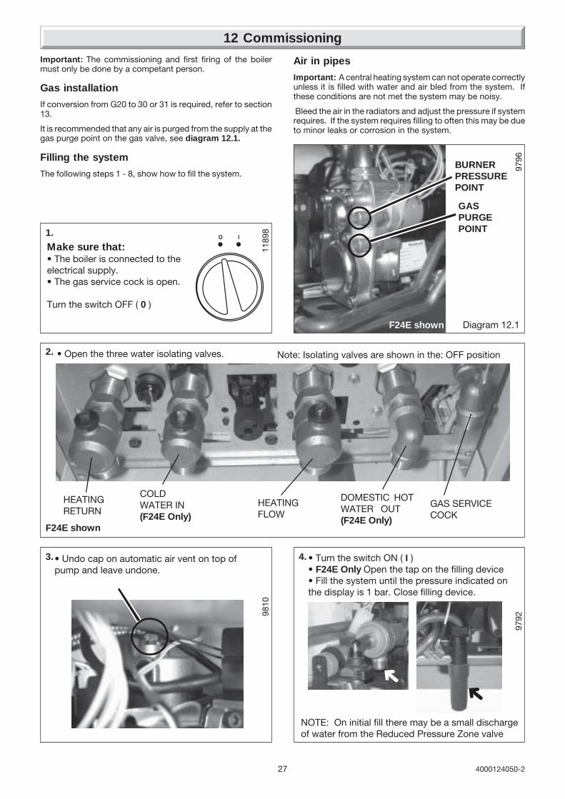
12 Commissioning
Important: The commissioning and first firing of the boilermust only be done by a competant person.
Gas installation
If conversion from G20 to 30 or 31 is required, refer to section13.
It is recommended that any air is purged from the supply at thegas purge point on the gas valve, see diagram 12.1.
Filling the system
The following steps 1 - 8, show how to fill the system.
1.
Make sure that:• The boiler is connected to theelectrical supply.• The gas service cock is open.
Turn the switch OFF ( 0 )
• Turn the switch ON ( I )• F24E Only Open the tap on the filling device• Fill the system until the pressure indicated onthe display is 1 bar. Close filling device.
F24E shown
9810
9796
GASPURGEPOINT
Diagram 12.1
3.• Undo cap on automatic air vent on top ofpump and leave undone.
9792
4.
➜
Air in pipes
Important: A central heating system can not operate correctlyunless it is filled with water and air bled from the system. Ifthese conditions are not met the system may be noisy.
Bleed the air in the radiators and adjust the pressure if systemrequires. If the system requires filling to often this may be dueto minor leaks or corrosion in the system.
F24E shown
1189
8
2. • Open the three water isolating valves.
HEATINGRETURN
COLDWATER IN(F24E Only)
HEATINGFLOW
DOMESTIC HOTWATER OUT(F24E Only)
GAS SERVICECOCK
Note: Isolating valves are shown in the: OFF position
NOTE: On initial fill there may be a small dischargeof water from the Reduced Pressure Zone valve
➜
BURNERPRESSUREPOINT

284000124050-2
12 Commissioning
Ins
061a5. • Bleed each radiator to remove air, ensure all
bleed screws are re-tightened.• If necessary repressurise the system, refer toprocedure 4
➜
Ins
062a
8. • Open various hot water taps to bleed system
98106. • Leave cap open on automatic air vent.
7. • Ensure the display indicates a system pressureof 1.0 bar adjust if necessary.
1021
7
Adjusting the Central heating output.
The central heating output is factory preset to approx. 15kW.
If a different central heating output is required, proceed asfollows:
To gain access to potentiometer P3, unclip the control box,see diagram 11.1.
15 kW maxiP.max.
mini
1ON
P315 kW maxiP.max.
miniP3
P6
P70
+
P6
1ON
Diagram 12.2
POTENTIOMETER P3
USERINTERFACEBOARD
POTENTIOMETER P6
MANOMETER
1206
6SW1DIPSWITCH
Factory set in"OFF" position
The potentiometer P3, is shown in diagram 12.2,to adjust tothe required heating output, insert a small flat edge screwdriver into the arrowed slot in potentiometer P3, turn clockwiseto adjust to the desired setting. Use a manometer to monitorthe burner pressure.
Dip Switches
The position of the SW1Dip Switch(s), see diagram 12.2, andthe table below can be used to change the operation of the
PUMP OPERATION DIP SWITCH 1
WITH BURNER ON
WITH HEATING OFF*
DEMAND
FACTORY SETTING * GB/IE PREFFERED SETTING
pump and maximum heating temperature of your boiler.

29 4000124050-2
Diagram 14.1
9718A
Bypass
The boiler has a built-in bypass, refer to diagram 14.1.
The boiler is supplied with the bypass open half a turn. It shouldnot be necessary to adjust the bypass, but if required ensurethat under no circumstances does the flow rate fall below thefigures specified, refer to table 1. in section 3 (turn clockwise'A' to close the valve ).
F24E shown
12 Commissioning
Should it be necessary to change the gas type, a conversion kitwith instructions will be required.
This modification must only be carried out by a competentperson.
Conversion natural gas (G20) to G30/G31 Part No. A20027.
Setting the step pressure.Adjusting the step pressure may be a necessary operation aftergas conversion or after changing the gas control valve when anew replacement part is required.
Proceed as follows:
• Gain access to the gas control valve, connect a pressuregauge.
13 Changing Gas Type
When all adjustments are completed.
• Adjust heating temperature to maximum.
• Check that any external controls, if fitted, are calling for heat(set room thermostat to maximum).
• Allow the temperature to rise to the maximum value, with allradiator valves open. The temperature rise will cause release ofthe air contained in the water of the central heating system.
• Air driven towards the boiler will be automatically releasedthrough the automatic air vent.
• The air trapped at the highest point of the system must bereleased by bleeding the radiators. Check the burner gas raterequired, ten minutes after lighting. Refer to Data Label onelectrical controls box. Should there be any doubt about thegas rate it should be checked at the meter, refer to technicaldata.
On reaching maximum temperature, the boiler should beturned off and the system drained as rapidly as possible whilststill hot.
• Refill system to a pressure of between 1 and 2 bar and ventas before.
• Restart boiler and operate until a maximum temperature isreached. If necessary, refer to section 14 to adjust the bypass.Shut down boiler and vent heating system. If necessary, top upheating system and make sure that a pressure of at least 1 baris indicated when system is COLD.
F24E Only Flush the domestic hot water system by opening thehot water taps for several minutes.
CompletionAdjust the boiler temperature control and any system controlsto their required settings.
For IE, it is necessary to complete a "Declaration of Conformity"to indicate compliance to I.S.813. An example of this is givenin the current edition of I.S.813.
• Unclip the control box, see diagram 11.1.
• Run the appliance in heating mode.
• Read the burner pressure setting in heating mode, before theboiler modulates.
• Adjust the central heating output to the minimum setting byadjusting potentiometer P3, refer to commissioning section.
• Adjust the potentiometer P6 burner pressure to the desiredvalue, by inserting a small flat edge screw driver into thearrowed slot, turn to adjust to the desired setting, see diagram12.2.
• Return the potentiometer P3 to its initial value.
Please ensure the “Benchmark” logbook is completed and leftwith the user and the magnetic lighting instruction label isplaced on the surface of the boiler casing.
Instruct the UserInstruct and demonstrate the lighting procedure and advise theuser on the safe and efficient operation of the boiler.
Instruct on and demonstrate the operation of any heatingsystem controls.
Advise the user on the use and maintenance of any scalereducer and pass on any relevant instructional documents.
Advise that to ensure the continued efficient and safe operationof the boiler it is recommended that it is checked and servicedat regular intervals. The frequency of servicing will dependupon the installation conditions and usage, but in general, oncea year should be enough.
Draw attention, if applicable, to the current issue of the GasSafety (Installation and Use) Regulations, Section 35, whichimposes a duty of care on all persons who let out any propertycontaining a gas appliance in the UK.
It is the Law that any servicing is carried out by a competentperson.
Advise the user of the precautions necessary to preventdamage to the system, boiler and the building, in the event ofthe heating system being out of use during frost or freezingconditions.
Advise the user that the permanent mains electrical supplySHOULD NOT be switched off, as the built in frost protectionand pump saver program would not be operable.
Reminder, leave these instructions and the ‘Benchmark’ logbookwith the user.
14 Bypass Setting

304000124050-2
REMEMBER, when replacing a part on this appliance, use onlyspare parts that you can be assured conform to the safety andperformance specification that we require. Do not usereconditioned or copy parts that have not been clearly authorisedby Hepworth Heating.
To ensure the continued efficient and safe operation of theboiler it is recommended that it is checked and serviced atregular intervals. The frequency of servicing will depend uponthe particular installation conditions and usage, but in generalonce a year should be enough.
It is the law that any servicing is carried out by a competantperson.
15.1 Products of combustion check
Note: To obtain a products of combustion reading, unscrewthe left hand sampling point cap on the flue elbow, located ontop of boiler, see diagram 15.1.
Connect the analyser tube onto sampling point.
Refer to the combustion product values in Section 1 TechnicalData.
Switch on the electrical supply and gas supply, then operatethe boiler.
On completion of the test switch off the electrical supply andthe gas supply, remove analyser tube and replace samplingpoint cap.
15 Routine Cleaning and Inspection
9532
PRODUCTSSAMPLINGPOINT
Diagram 15.1
15.2 Service Check and Preparation.
• Isolate boiler from the gas and electrical supplies.
• (F24E Only) Drain the Domestic hot water circuit, refer todiagram 15.2.
• Drain the boiler, refer to diagram 15.2.
• On completion check all gas-carrying parts for soundnesswith leak detection fluid.
Note: Isolating cocks water and gas are shown in the: OFF position Diagram 15.2
To Drain the Domestic hot water circuit (F24E Only)
• Close boiler isolating valve (b).
• Turn on one or more hot water taps.
To Drain the boiler
• Close isolating valves (a) and (c).
• Open the boiler drain valve (f).
F24E shown
(f)BOILERDRAIN VALVE
(e)(d)(a)HEATINGRETURN
COLD WATERINLET (F24E Only)
HEATINGFLOW
DOMESTIC HOTWATER OUTLET(F24E Only)
GAS SERVICECOCK
(c)(b)

31 4000124050-2
15.3 Front panel
• Unscrew and remove the two retaining screws from thebottom of the front panel.
• Remove front panel by lifting up and forward.
15.4 Control panel
• Lower forwards to gain access to lower part of boiler.
15.5 Sealed chamber cover
• Unscrew and remove the two retaining screws from thesealed chamber cover, see diagram. 15.3.
• Lift cover up and off pins on top of boiler.
15.6 Side panels (for ease of access ifavailable), refer to diagram 15.4
• Unscrew and remove the two retaining screws from front ofeach side panel.
• Left hand side panel only disconnect the control panelretaining strap at the control panel.
• Unhook each panel from the front retaining tabs.
• Pull each panel forward from the rear retaining tabs toremove.
15.7 Combustion chamber cover
• Unscrew and remove the two screws securing combustionchamber cover to combustion chamber, see diagram 15.5.
• Remove combustion chamber cover from boiler.
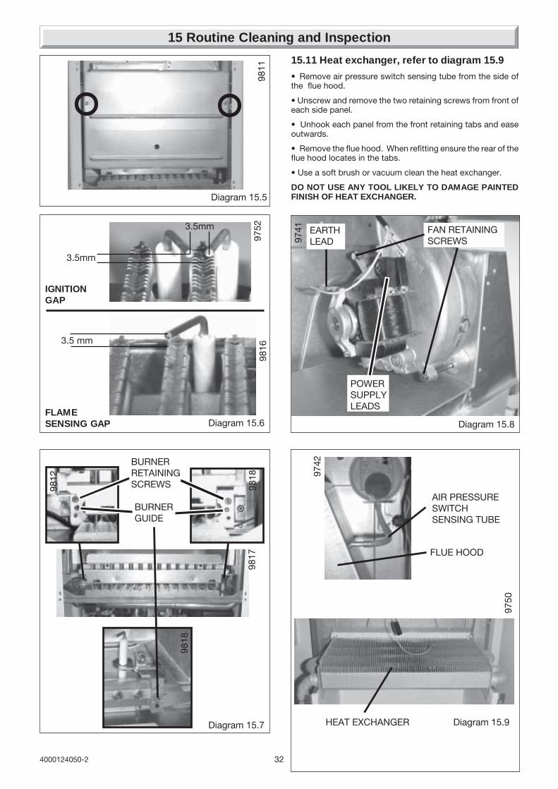
15.8 Ignition and Flame Sensing Gaps
• Check that the ignition and flame sensing gaps as shown indiagram 15.6. Note: To gain access to ignition and senseelectrodes for removal, refer to Section, 18.11 and 18.12 inReplacement of Parts.
15.9 Burner, refer to diagram 15.7
• Unscrew and remove the two burner retaining screws.
• Remove burner from boiler by easing it forward off the twoburner guides, taking care not to damage the insulation.
• Clean burner by washing in soapy water. Dry thoroughlybefore refitting.
Note: To gain access to injectors for removal and cleaning,refer to Section, 18.8.
15.10 Fan, refer to diagram 15.8
• Disconnect power supply leads and earth lead from fan.
• Unscrew and remove the two fan retaining bolts.
• Ease the fan down and forwards to remove.
15 Routine Cleaning and Inspection
Diagram 15.3
9533
Diagram 15.4
9533
9733
9734
F24E shown
324000124050-2
3.5mm
3.5mm
IGNITIONGAP
15 Routine Cleaning and Inspection
Diagram 15.6
9752
Diagram 15.5
3.5 mm
FLAMESENSING GAP
9811
9816
Diagram 15.8
9741
POWERSUPPLYLEADS
EARTHLEAD
FAN RETAININGSCREWS
Diagram 15.7
BURNERGUIDE
BURNERRETAININGSCREWS
9818
9817
9818
9812 97
42
Diagram 15.9
FLUE HOOD
HEAT EXCHANGER
AIR PRESSURESWITCHSENSING TUBE
9750
15.11 Heat exchanger, refer to diagram 15.9
• Remove air pressure switch sensing tube from the side ofthe flue hood.
• Unscrew and remove the two retaining screws from front ofeach side panel.
• Unhook each panel from the front retaining tabs and easeoutwards.
• Remove the flue hood. When refitting ensure the rear of theflue hood locates in the tabs.
• Use a soft brush or vacuum clean the heat exchanger.
DO NOT USE ANY TOOL LIKELY TO DAMAGE PAINTEDFINISH OF HEAT EXCHANGER.

33 4000124050-2
15 Routine Cleaning and Inspection
9822
Diagram 15.10FILTER
DOMESTIC WATERINLET FILTERHOUSING
CLIP
F24E only
RETAININGCLIP
FILTER FLAT
1193
5
Diagram 15.11F24E shown
15.12 (F24E Only) Domestic water inlet filter,refer to diagram 15.10
If the water flow rate through the appliance has reduced it maybe necessary to clean or replace the domestic water inlet filter.
• Close isolating valve (b) on cold water inlet.
• Pull out slotted clip securing the filter in its housing, remove thefilter to clean or renew if necessary.
Push the filter fully into its housing and replace the securing clip.
• Open isolating valve, (b) diagram 15.2, on cold water inlet andtest the Domestic Hot Water circuit for soundness.
15.13 Central Heating Filter, refer to diagram15.11
Remove the filter retaining clip and filter clean or renew ifnecessary.
Push the filter fully into its housing, ensuring the correctorientation. The flat and hole in the filter as shown. Secure withretaining clip.
15.14 Sealed chamber cover seal check
• Check the condition of the seal, replace as required.
• To replace remove the old seal, thoroughly clean the casingsurfaces. Fit new seal, it is supplied to the correct length, seediagram 18.25.
15.15 Combustion chamber insulation
• Check the condition of the combustion chamber insulation.If renewing, refer to Section 18.14.
15.16 Flue system
• Check externally to make sure that flue is not blocked
• Inspect flue system to make sure that all fittings are secure.
15.17 Reassembly of parts removed forservicing
All parts are replaced in reverse order to removal.
1193
4

344000124050-2
16 Fault Finding
Before trying to operate the boiler make sure that :
• All gas supply cocks are open and that the gas supply hasbeen purged of air.
• The heating system pressure is at least 1 bar.
• There is a permanent mains supply to the boiler and that thepolarity is correct.
WARNING. Always isolate the boiler from the electrical supplybefore carrying out any electrical replacement work.
Always check for gas soundness after any service work.
Should there be any doubt about the voltage supply to any ofthe components, it is possible to carry out a simple electricaltest to ensure all is operational in that area.
IMPORTANT: On completion of the fault finding task which hasrequired the breaking or remaking of the electrical connections,the continuity, polarity, short circuit and resistance to earthchecks must be repeated using a suitable multimeter.
Overheat thermostat reset button
Refer to Section 18.10 to locate the overheat thermostatreset button.
Depress the button to reset.
9749
OVERHEATTHERMOSTAT
RESETBUTTON
Diagram 16.1
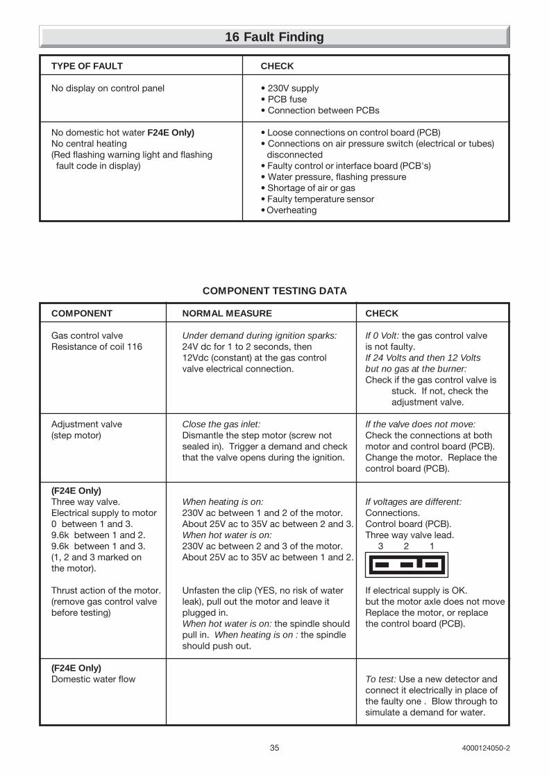
35 4000124050-2
16 Fault Finding
COMPONENT NORMAL MEASURE CHECK
Gas control valve Under demand during ignition sparks: If 0 Volt: the gas control valveResistance of coil 116 24V dc for 1 to 2 seconds, then is not faulty.
12Vdc (constant) at the gas control If 24 Volts and then 12 Voltsvalve electrical connection. but no gas at the burner:
Check if the gas control valve isstuck. If not, check theadjustment valve.
Adjustment valve Close the gas inlet: If the valve does not move:(step motor) Dismantle the step motor (screw not Check the connections at both
sealed in). Trigger a demand and check motor and control board (PCB).that the valve opens during the ignition. Change the motor. Replace the
control board (PCB).
(F24E Only)Three way valve. When heating is on: If voltages are different:Electrical supply to motor 230V ac between 1 and 2 of the motor. Connections.0 between 1 and 3. About 25V ac to 35V ac between 2 and 3. Control board (PCB).9.6k between 1 and 2. When hot water is on: Three way valve lead.9.6k between 1 and 3. 230V ac between 2 and 3 of the motor. 3 2 1(1, 2 and 3 marked on About 25V ac to 35V ac between 1 and 2.the motor).
Thrust action of the motor. Unfasten the clip (YES, no risk of water If electrical supply is OK.(remove gas control valve leak), pull out the motor and leave it but the motor axle does not movebefore testing) plugged in. Replace the motor, or replace
When hot water is on: the spindle should the control board (PCB).pull in. When heating is on : the spindleshould push out.
(F24E Only)Domestic water flow To test: Use a new detector and
connect it electrically in place ofthe faulty one . Blow through tosimulate a demand for water.
COMPONENT TESTING DATA
TYPE OF FAULT CHECK
No display on control panel • 230V supply• PCB fuse• Connection between PCBs
No domestic hot water F24E Only) • Loose connections on control board (PCB)No central heating • Connections on air pressure switch (electrical or tubes)(Red flashing warning light and flashing disconnected fault code in display) • Faulty control or interface board (PCB's)
• Water pressure, flashing pressure• Shortage of air or gas• Faulty temperature sensor• Overheating

364000124050-2
16 Fault Finding
FAULT: NO HOT WATER, BUT THE HEATING IS WORKING
Is the water flow rate greaterthan 1.7l/min. (threshold figure).
NOCheck the cold water inlet filter
for dirt. Is the cold water tap fully open ?Check the heat exchanger for scaling.
Is flow detector operating ? NO Change or clean it.
YES
Check the connectors on theflow sensor and the control board (PCB).
If the fault persists, fit a relplacementcontrol board (PCB).
YES
11800
F24E ONLY
FAULT: NO HEATING
Are the external heatingcontrols calling for heat?
Is the polarity correct?
Rectify fault on external controls.NO
Rectify, check the 230Vcontrols board.
NO
Faulty main PCB.NO
YES
Connect 1 and 2 on J10,does boiler fire in central heating?
YES
Faulty 230V controls board.
YES

37 4000124050-2
F1 or F4 FAULT DISPLAYEDFAULT: THE BURNER LIGHTS, THEN GOES OUT.
CHECKTHE
PROBECHECKTHE MAINS
FAULT NOT FOUND
The flame is spreading across thewhole burner, but not being detected.
With the power turned off, check thecontinuity between the flame senseelectrode and terminal H2 . 4 on thecontrol board (PCB). Check theconnector on the end of the wire.Check that the spark electrode ispointing towards the flame.Check the spark electrode. Change it.
If the problem persists, change thecontrol board (PCB).(flame detection module faulty).
11873F1 FAULT DISPLAYED
FAULT: THE BURNER LIGHTS BUT THEN GOES OUT. THERE IS NO FLAME DETECTED.
Check that the gas taps are fully openCheck the gas pressure.
NO
YES
The flame is not spreading acrossthe whole burner and is not reaching
the sensing electrode. Is the gaspressure correct?
Is the boiler actually designed for thegas being used.
Change the gas type for the boiler(gas conversion kit).
NO
YES
Clean the gas filter.Clean the burner.
16 Fault Finding

384000124050-2
16 Fault Finding
F1 FAULT DISPLAYEDFAULT: THE BURNER DOES NOT LIGHT AT ALL, BUT THERE IS AN IGNITION SPARK.
NO
NO
YES
YES
Are the gas taps on?
Test the gas control valve.
Turn on the gas taps.
Check the wiring.If the problem persists, change thecontrol board (PCB).
Is there 24Vdc at the gas control valve?for testing see component testing data.
Check resistance of safety valve coil.
FAULT: THE ROOM TEMPERATURE IS INADEQUATE AND RADIATORS ARE LUKE-WARM.
YES
NO
Is the heating temperature on the boilerset high enough?
Turn up settings
YES
Is the heating power adequate?- Check set point P3. (Refer to Commissioning)- Check dip switch setting. (Refer to Commissioning)- Check the adjustment of the by-pass internal andexternal (If fitted). - F24E Only Check the 3-way valveis not passing into the domestic hot water heat exchanger.
Is the room thermostat and or radiatorset high enough and calling for duty?

39 4000124050-2
• CHECK CONTINUITY OF IGNITION (ELECTRODES AND LEADS)• CHECK POWER SUPPLY FROM PCB TO IGNITION UNIT
Air flow switch take-off.
CONNECTIONS TO THE AIR PRESSURE SWITCH
Pr
3
2 1
P2
P1
LH
Electrical contacts.
FAULT: THE FAN RUNS BUT THERE ARE NO SPARKS.
11877
FAULT: THE FAN DOES NOT START.
Check continuity of fan harness.NO
YES
Is there is 230V acat fan during demand?
Faulty fan, replace.
YES
Faulty PCB, replace.
11876
16 Fault Finding
FAULT: THE WATER AT THE TAPS IS LUKE-WARM.
NO
YES
Check that the cold water inlet restrictor is fitted.Check the rate of flow.Check burner pressure is correct.
Check the 3-way valve is not passing into the radiators. (The radiators shouldstay cold in Summer setting)
Is the temperature higher if you reducethe flow through the taps?
11875F24E ONLY

404000124050-2
17 Wiring Diagram F24E
1022
4
bk- BLACKw- WHITEg/y- GREEN/
br - BROWNb- BLUEp- PINKg- GREY
r - REDor- ORANGEgn- GREENy- YELLOWYELLOW
KEY
WATERPRESSURESENSOR
USER INTERFACE
THERMISTORCH
FLOWSENSOR
PROGRAMMER
PUMP
IGNITORUNIT
GASCONTROL
VALVE
w w
wg
b b
bk bk
3
1
b
CHASSISEARTH
230V~50HzPERMANENT
MAINS SUPPLYFUSED AT 3A
PLUG
FUSE125mAT
J2
J7
J4
J12
S1
J1
J13J15 J11
H5
H2
H1
H4
H3
H8
H6
H7
ON/OFFSWITCH
AIR PRESSURESWITCHFAN
THREE-WAYVALVE
SENSEELECTRODE
IGNITIONELECTRODES
g/y
g/y
CHASSISEARTH
bk
br
wg
wg
wg
p
por
ygn
b
b
w r
br
bg/y
g/y
br
or
OVERHEATTHERMOSTAT
g/y
g/y
br
br
b
b
g/y
4
3
21
br
br
b
J10
230V SWITCHED LIVE FROM HEATING CONTROLS.
230V SWITCHED LIVE FROM OPTIONAL FROST STAT.
REMOVE THE LINK IF FITTINGVOLTAGE FREE OR 230VEXTERNAL CONTROLS.IF THE LINK IS NOT REMOVEDTHE BOILER WILL RUNCONTINUOUSLY.
MAINS VOLTAGE HEATING CONTROLS PLUG
VOLTAGE FREEHEATING CONTROLSPLUG
CONTROLSINTERFACE
LINK
w yr gn
b
REMOVE VOLTAGE FREE LINK
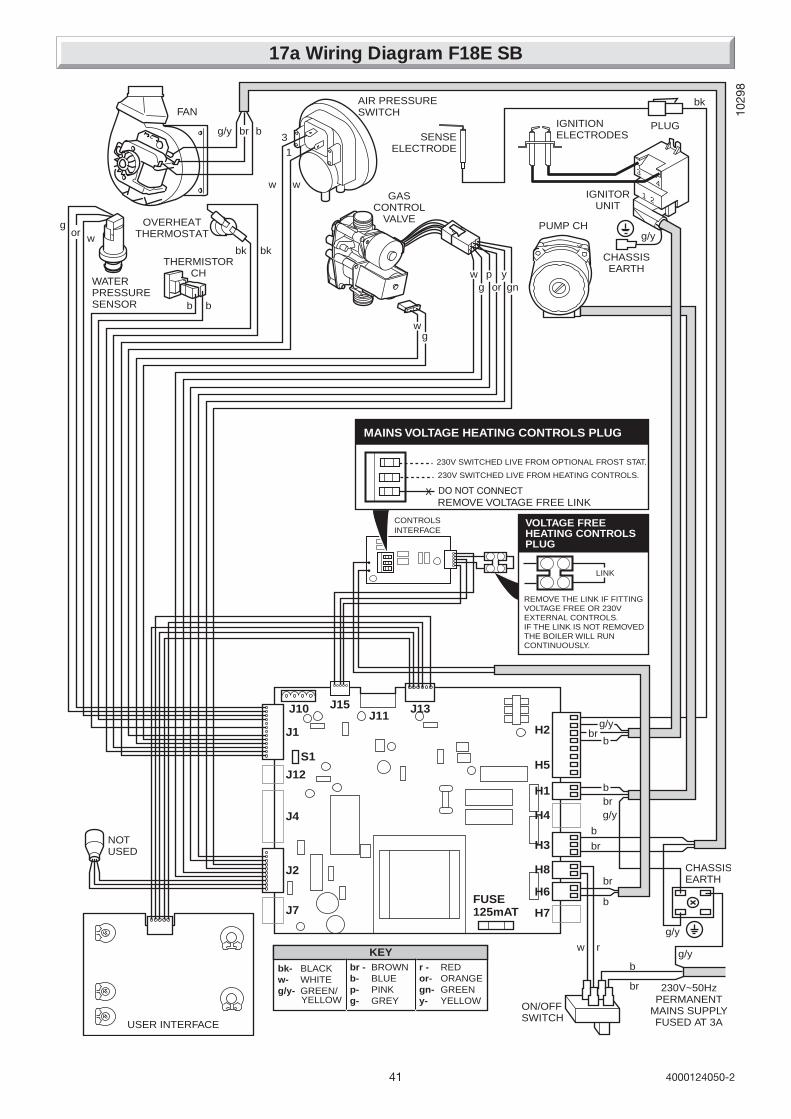
41 4000124050-2
17a Wiring Diagram F18E SB
bk- BLACKw- WHITEg/y- GREEN/
br - BROWNb- BLUEp- PINKg- GREY
r - REDor- ORANGEgn- GREENy- YELLOWYELLOW
KEY
WATERPRESSURESENSOR
USER INTERFACE
THERMISTORCH
PUMP CH
IGNITORUNIT
GASCONTROL
VALVE
w w
wg
b b
bk bk
3
1
b
CHASSISEARTH
230V~50HzPERMANENT
MAINS SUPPLYFUSED AT 3A
PLUG
FUSE125mAT
J2
J7
J4
J12
S1
J1
J13J10J11
H5
H2
H1
H4
H3
H8
H6
H7
ON/OFFSWITCH
AIR PRESSURESWITCHFAN
SENSEELECTRODE
IGNITIONELECTRODES
g/y
g/y
CHASSISEARTH
bk
br
wg
wg
por
ygn
b
b
w r
br
bg/y
g/y
br
orOVERHEAT
THERMOSTAT
g/y
g/ybrb
br
b
4
3
21
br
NOTUSED
J15
230V SWITCHED LIVE FROM HEATING CONTROLS.
230V SWITCHED LIVE FROM OPTIONAL FROST STAT.
REMOVE THE LINK IF FITTINGVOLTAGE FREE OR 230VEXTERNAL CONTROLS.IF THE LINK IS NOT REMOVEDTHE BOILER WILL RUNCONTINUOUSLY.
MAINS VOLTAGE HEATING CONTROLS PLUG
VOLTAGE FREEHEATING CONTROLSPLUG
CONTROLSINTERFACE
LINK
REMOVE VOLTAGE FREE LINK
1029
8

424000124050-2
18 Replacement of Parts
IMPORTANT INFORMATION
WARNING: Before commencing the replacement of anycomponent, isolate appliance from electrical supply and turnoff gas at service cock.
Replacement of parts must be carried out by a competentperson.
When replacing components it may be necessary to renewsealing washers, gaskets and 'O' rings. If new ones aresupplied with replacement components they must be used.
All parts are replaced in reverse order to removal.
If any gas-carrying components are disturbed, removed orreplaced it will be necessary on completion of assembly to testfor gas soundness and purge in accordance with the currentissue of BS6891 or in IE, the current edition of I.S.813 "DomesticGas Installations".
18.1 Central heating thermistor
Before starting refer to the front of Section 18 Importantinformation.
• Remove the front panel, refer to Section 15.3.
• Lower the control panel, refer to Section 15.4.
• Locate central heating thermistor on heating flow pipe oncentre of boiler, see diagram 18.2.
• Unclip thermistor from pipe.
• Disconnect electrical connections from thermistor.
• Fit electrical connections to replacement thermistor and fitthermistor to pipe. The polarity is not important.
Diagram 18.2
9550
Diagram 18.1
To Drain the central heating circuit
• Open drain valve fitted at the lowest point in the system.
• Allow air into the system by opening a radiator bleed screw or the boilers drain valve (f).
To Drain the Domestic hot water circuit (F24E Only)
• Close boiler isolating valve (b).
• Turn on one or more hot water taps.
To Drain the boiler
• Close the isolating valves (a), (b) and (c) .
• Open the boiler drain valve (f).
F24E shown
(f)BOILERDRAIN VALVE
Note: Isolating cocks water and gas are shown in the: OFF position
(e)(d)(a)HEATINGRETURN
COLD WATERINLET (F24E Only)
HEATINGFLOW
F24E shown
DOMESTIC HOTWATER OUTLET(F24E Only)
GAS SERVICECOCK
(c)
CENTRAL HEATINGTHERMISTOR
(b)

43 4000124050-2
9646
Diagram 18.3
SENSINGTUBE
AIR PRESSURESWITCH
18.2 Fan.
Before starting refer to the front of Section 18 Importantinformation.
• Remove the front panel, refer to Section 15.3.
• Remove the sealed chamber cover, refer to Section 15.5.
• Remove the fan, refer to Section 15.10.
18.3 Air pressure switch
Before starting refer to the front of Section 18 Importantinformation.
• Remove the front panel, refer to Section 15.3.
• Remove the sealed chamber cover, refer to Section 15.5.
• Locate air pressure switch situated at the top right hand side,see diagram 18.3.
• Remove air pressure switch tube.
Note: Do not fit tube until the air pressure switch is in position.
• Disconnect air pressure switch electrical connections.
• Unclip to remove air pressure switch.
18.4 (F24E Only) Domestic water inlet filter
If the water flow rate through the appliance has reduced it maybe necessary to clean or replace the water inlet filter, refer tosection 15.12.
Before starting refer to the front of Section 18 Importantinformation.
• Remove the front panel, refer to Section 15.3.
• Lower the control panel, refer to Section 15.4.
• Clean or replace the water inlet filter, refer to Section 15.12.
18.5 Central Heating Filter
It may be necessary to clean or replace the central heating filter.
Before starting refer to the front of Section 18 Importantinformation.
• Isolate flow and return valves (a) and (c).
• Clean or replace the central heating filter, refer to Section15.13.
18.6 ( F24E Only) Cold water inlet restrictor
Before starting refer to the front of Section 18 Importantinformation.
• Remove the front panel, refer to Section 15.3.
• Lower the control panel, refer to Section 15.4.
• Isolate cold water inlet valve (b).
Drain down domestic hot water circuit of boiler only, refer torelevant part of diagram 18.1.
• Undo union nuts from boiler cold water in isolating valve.
• Clean and inspect restrictor, replace if necessary, see diagram18.4.
18.7 Burner, refer to Section 15.9.
Before starting refer to the front of Section 18 Importantinformation.
• Remove the front panel, refer to Section 15.3.
18 Replacement of Parts
ELECTRICALCONNECTORS
RETAININGCLIPS
• Lower the control panel, refer to Section 15.4.
• Remove the sealed chamber cover, refer to Section 15.5.
• Remove the combustion chamber cover, refer to Section15.7.
• Remove burner from boiler, refer to Section 15.9.
18.8 Burner injectors, refer to diagram 18.5.
Before starting refer to the front of Section 18 Importantinformation.
• Remove the front panel, refer to Section 15.3.
• Lower the control panel, refer to Section 15.4.
• Remove the sealed chamber cover, refer to Section 15.5.
• Remove the combustion chamber cover, refer to Section15.7.
• Remove burner from boiler, refer to Section 15.9.
• Remove and replace injectors as required.
Note: The injectors may be cleaned, remove injectors inspectand clean. Do not use a wire or sharp implement.
Note: Make sure that injector size, marked on each injector, isthe same as that given in ‘Section 1 Technical Data’ for thetype of gas being used.
Diagram 18.4
COLD WATER INLETRESTRICTOR
COLD WATER INISOLATING VALVE
F24E Only

444000124050-2
18 Replacement of Parts
18.9 Burner injector assembly, refer to diagram18.6.
Before starting refer to the front of Section 18 Importantinformation.
• Remove the front panel, refer to Section 15.3.
• Lower the control panel, refer to Section 15.4.
• Remove the sealed chamber cover, refer to Section 15.5.
• Remove the combustion chamber cover, refer to Section15.7.
• Remove burner from boiler, refer to Section 15.9.
• Undo the gas supply union nut from under the sealed chamber.
Note: The fibre washer between the burner injector assemblyand gas supply must be kept for use on reassembly.
• Undo and remove the sense and ignition electrode assemblies.
• Remove the burner injector assembly securing screws.
• Remove the burner injector assembly by lifting up, easing thegas connection through the grommet in the sealing chamber.
Note: Take care not to damage the insulation.
• When refitting burner injector assembly ensure the gasconnection locates correctly through the grommet.
Note: Make sure that injector size, marked on each injector, isthe same as that given in ‘Section 1 Technical Data’ for the typeof gas being used.
18.10 Overheat thermostat
Before starting refer to the front of Section 18 Importantinformation.
• Remove the front panel, refer to Section 15.3.
• Remove the sealed chamber cover, refer to Section 15.5.
• Locate overheat thermostat on heating flow pipe on right handside of boiler, see part of diagram 18.7.
• Disconnect electrical connections from thermostat
• Remove the thermostat and bracket assembly from heatingflow pipe by unclipping at the side of the bracket. Remove thethermostat, fit new thermostat and replace assembly.
• When refitting electrical connections to replacement thermostatthe polarity is not important.
18.11 Ignition electrode
Before starting refer to the front of Section 18 Importantinformation.
• Remove the front panel, refer to Section 15.3.
• Lower the control panel, refer to Section 15.4.
• Remove the sealed chamber cover, refer to Section 15.5.
• Remove the combustion chamber cover, refer to Section15.7.
• Remove burner from boiler, refer to Section 15.9.
• Remove the left hand side panel, refer to Section 15.6.
• Undo and remove screw securing electrode assembly to theburner injector assembly, see diagram 18.6.
• Disconnect the electrical connections at the ignition unit, seediagram 18.22. Note the routing of the cables.
18.12 Flame sense electrode
Before starting refer to the front of Section 18 Importantinformation.
• Remove the front panel, refer to Section 15.3.
• Lower the control panel, refer to Section 15.4.
• Remove the sealed chamber cover, refer to Section 15.5.
• Remove the combustion chamber cover, refer to Section 15.7.
• Remove burner, refer to Section 15.9.
• Remove the right hand side panel, refer to Section 15.6.
• Undo and remove screw securing sense assembly to theburner injector assembly, see diagram 18.6.
• Disconnect the electrical connection from the inline connector,Note the routing of the cable.
Diagram 18.7
Diagram 18.6
GAS SUPPLYPIPE
GROMMET
IGNITION ELECTRODEASSEMBLY
SENSE ELECTRODEASSEMBLY
9813
9820
Diagram 18.5
BURNER INJECTORBAR
9819
a
9749
PIPESECURINGCLIP 2 OFF
ELECTRICALLEADS
OVERHEATTHERMOSTAT
HEAT EXCHANGER
9750
RESETBUTTON
CLIP
9813

45 4000124050-2
18 Replacement of Parts
18.13 Heat exchanger, refer to diagram 18.7.
Before starting refer to the front of Section 18 Importantinformation.
• Remove the front panel, refer to Section 15.3.
• Remove the sealed chamber cover, refer to Section 15.5.
• Remove the combustion chamber cover, refer to Section15.7.
• Drain down central heating water circuit of the boiler only,refer to relevant part of diagram 18.1.
• Remove the fan, refer to Section 15.10.
• Remove air pressure switch sensing tube from the side of theflue hood, see diagram 15.9.
• Release both side panels, refer to section 15.6.
• Remove the flue hood, lift up and off. When refitting ensurethe rear of the flue hood locates in the tabs.
• Disconnect the electrical leads from the overheat thermostat.
• Remove the two pipe securing clips.
• Lift to remove the heat exchanger taking, care not to damagethe insulation.
18.14 Combustion chamber insulation, refer todiagram 18.8.
Before starting refer to the front of Section 18 Importantinformation.
• Remove the front panel, refer to Section 15.3.
• Remove the sealed chamber cover, refer to Section 15.5.
• Remove the combustion chamber cover, refer to Section15.7.
• Remove the heat exchanger, refer to Section 18.13.
• Pull out side insulation panels from combustion chamber.
• Tilt rear insulation panel forwards and out.
• Fit replacement insulation.
18.15 Printed circuit board (PCB), refer todiagram 18.9.
Before starting refer to the front of Section 18 Importantinformation.
• Remove the front panel, refer to Section 15.3.
• Lower the control panel, refer to Section 15.4.
• Undo and remove the two front retaining screws.
• Hinge up the control panel cover and ease forwards from therear retaining lugs to gain access to PCB. Do not strain thecables attached to the PCB. Note the routing of the cables.
• Carefully pull off electrical connections to PCB.
• Unclip and lift out PCB.
• Fit replacement PCB. Be careful not trap any of the cables.
Make sure that PCB connections are fully pushed ontoreplacement PCB.
F24E shown
Diagram 18.8
9824
aINSULATION
➜ ➜
Diagram 18.9
PCB (CONTROL BOARD)
CONTROLBOARDCOVER
1000
1
1002
1

464000124050-2
18 Replacement of Parts
18.16 User interface board, refer to diagram18.10.
Before starting refer to the front of Section 18 Importantinformation.
• Remove the front panel, refer to Section 15.3.
• Unclip control panel user interface and hinge forward . Do notstrain the cables.
• Disconnect the electrical connections from the user inter faceboard.
• Remove the two user inter face board retaining screws.
• Remove the user inter face board.
18.17 Mains switch, refer to diagram 18.10.
Before starting refer to the front of Section 18 Importantinformation.
• Remove the front panel, refer to Section 15.3.
• Unclip control panel user interface and hinge forward . Do notstrain the cables.
• Disconnect the electrical connections from mains switch.
• Remove the mains switch.
18.18 230V Controls board, refer to diagram18.10.
Before starting refer to the front of Section 18 Importantinformation.
• Remove the front panel, refer to Section 15.3.
• Unclip control panel user interface and hinge forward . Do notstrain the cables.
• Disconnect the electrical connection from the 230V controlsboard and the electrical connection from printed circuit board(PCB).
• Remove the 230V controls board retaining screw.
• Remove the 230V controls board.
18.19 (F24E Only) Analogue programmer, referto diagram 18.10
Before starting refer to the front of Section 18 Importantinformation.
• Remove the front panel, refer to Section 15.3.
• Unclip control panel user interface and hinge forward. Do notstrain the cables.
• Disconnect the electrical connection from the programmer.
• Undo the two securing screws and remove the programmer.
18.20 Central heating pump head, refer todiagram 18.11.
Before starting refer to the front of Section 18 Importantinformation.
• Remove the front panel, refer to Section 15.3.
• Lower the control panel, refer to Section 15.4.
• Drain down central heating water circuit of the boiler only,refer to relevant part of diagram 18.1.
Note: it is not necessary to drain down the entire heatingsystem to carry out this work.
• For ease of access if required remove the right hand sidepanel, refer to Section 15.6.
• Undo four head fixing screws and remove pump head.
• Gain access to the pump electrical connection box andremove cover.
• Disconnect pump cable from pump (avoid straining cables).
• Connect electrical connection to replacement pump head.
• Fit replacement pump head.
Diagram 18.10F24E shown
➜ ➜
CONTROL PANEL
9762
USER INTERFACEBOARD
➜
➜
1001
9
➜
➜
230V CONTROLSBOARD
MAINSSWITCH
PROGRAMMER
Diagram 18.11
9757
PUMP HEAD
PUMPELECTRICALCONNECTIONBOX
HEX HEADSCREW(4 OFF)
F24E shown

47 4000124050-2
18 Replacement of Parts
18.21 (F24E Only) Filling system tap, refer todiagram 18.12.
Before starting refer to the front of Section 18 Importantinformation.
• Remove the front panel, refer to Section 15.3.
• Lower the control panel, refer to Section 15.4.
• Drain down the hotwater circuit, refer to relevant part ofdiagram 18.1.
• Pull of the filling loop tap extension.
• Pull out slotted metal clip securing tap into housing, removetap.
• Pull out slotted metal clip and remove pipe from tap.
18.22 (F24E Only) Reduced pressure zonevalve (RPZ), refer to diagram 18.12.
Before starting refer to the front of Section 18 Importantinformation.
• Remove the front panel, refer to Section 15.3.
• Lower the control panel, refer to Section 15.4.
• Drain down the boiler only, refer to relevant part of diagram18.1.
• Pull out slotted metal clip securing pipe to RPZ.
• Pull out slotted metal clip securing RPZ into housing, removeRPZ.
18.23 Boiler drain point, refer to diagram18.13.
Before starting refer to the front of Section 18 Importantinformation.
• Remove the front panel, refer to Section 15.3.
• Lower the control panel, refer to Section 15.4.
• Drain down the boiler only, refer to relevant part of diagram18.1.
Pull out slotted metal clip securing boiler drain valve intohousing, remove boiler drain valve.
18.24 (F24E Only) Water flow sensor, refer todiagram 18.14.
Before starting refer to the front of Section 18 Importantinformation.
• Remove the front panel, refer to Section 15.3.
• Lower the control panel, refer to Section 15.4.
Drain down the hotwater circuit, refer to relevant part ofSection 18.1.
• Undo the union nut on the cold water inlet isolating valve.
• Pull out slotted metal clip securing filling system tap intohousing, swing the tap forwards.
• Pull out the two slotted metal clips retaining the domesticwater inlet filter housing.
• Remove domestic water inlet filter housing.
• Remove electrical connections from water flow sensor.
• Pull off slotted metal clip and remove water flow sensor.
➜➜
9758
Diagram 18.15
SYSTEM WATER PRESSURESENSOR BYPASS VALVE
9760
Diagram 18.16
AIRVENT
CAP
Diagram 18.14
WATER FLOWSENSOR
➜
➜
9765➜ ➜
F24E only
F24E shown
F24E shown
➜

484000124050-2
18 Replacement of Parts
18.25 System water pressure sensor, refer todiagram 18.15.
Before starting refer to the front of Section 18 Importantinformation.
• Remove the front panel, refer to Section 15.3.
• Lower the control panel, refer to Section 15.4.
Drain down the boiler, refer to relevant part of Section 18.1.
• Remove electrical connections from water pressure sensor.
• Pull off slotted metal clip and remove water pressure sensor.
Please ensure that the new "O" ring and clip supplied are fitted.
18.26 Bypass valve, refer to diagram 14.1.
Before starting refer to the front of Section 18 Importantinformation.
• Remove the front panel, refer to Section 15.3.
• Lower the control panel, refer to Section 15.4.
Drain down the boiler, refer to relevant part of Section 18.1.
• Remove the ignition unit, refer to Section 18.33.
Pull out slotted metal clip, ease out bypass valve from bypassvalve housing.
18.27 Automatic air vent, refer to diagram18.16.
Before starting refer to the front of Section 18 Importantinformation.
• Remove the front panel, refer to Section 15.3.
• Lower the control panel, refer to Section 15.4.
• Drain down the boiler only, refer to relevant part of diagram18.1.
• Unscrew to remove automatic air vent.
• After fitting replacement automatic air vent ensure the cap isopen.
18.28 Gas Control valve, refer to diagram18.17.
Before starting refer to the front of Section 18 Importantinformation.
• Remove the front panel, refer to Section 15.3.
• Lower the control panel, refer to Section 15.4.
• Disconnect gas supply pipes union nuts at the gas controlvalve.
• Disconnect supply pipe union nut at the burner injector bar.
• Remove the locking nut and brass washer from underside ofgas control valve.
• Ease gas control valve forwards and disconnect electricalconnections to gas control valve.
• Withdraw gas control valve assembly.
Note: Use the new washers supplied with the gas control valve.
• Fit gas valve restrictor to replacement gas control value.
• Fit replacement gas control valve.
Check the Min. gas pressure and if it requires adjusting, referto Section 13 Changing Gas Type.
1158
5
Diagram 18.19
PRESSURERELIEFVALVE
➜
➜
1001
8
Diagram 18.18
STEPPERMOTOR
➜
➜➜
GAS CONTROLVALVE
F24E shown
9781
Diagram 18.17
GAS CONTROLVALVE
➜➜
➜
➜
9782
1159
1
F24E shown

49 4000124050-2
18 Replacement of Parts
18.29 Gas control valve stepper motor, refer todiagram 18.18
Before starting refer to the front of Section 18 Importantinformation.
• Remove the front panel, refer to Section 15.3.
• Lower the control panel, refer to Section 15.4.
• Remove the gas control valve, refer to Section 18.28.
• Disconnect the electrical connection from stepper motor.
• Remove the two screws securing stepper motor to the gascontrol valve.
• Fit replacement gas control valve stepper motor.
• Note: Take care not to damage the 'O' ring.
18.30 Discharge safety valve, refer to diagram18.19.
Before starting refer to the front of Section 18 Importantinformation.
• Remove the front panel, refer to Section 15.3.
• Lower the control panel, refer to Section 15.4.
• Undo discharge pipe union nut.
• Pull out slotted metal clip from valve body and remove valve.
18.31 (F24E Only) Three-way valve head, referto diagram 18.20.
Before starting refer to the front of Section 18 Importantinformation.
• Remove the front panel, refer to Section 15.3.
• Lower the control panel, refer to Section 15.4.
• Remove gas control valve, refer to Section 18.28. (It will notbe necessary to remove the gas control electrical cables).
• Remove electrical plug from valve head.
• Pull out slotted metal clip from valve body and remove valvehead from body.
• Fit replacement valve head.
Note :
1) When refitting clip, ensure that letters YES are as shown.
2) It is not necessary to drain boiler to carry out this work.
Diagram 18.21
1001
7
Diagram 18.22
9767
IGNITIONUNIT
➜➜➜
➜
THREE WAYVALVE/ BYPASSHOUSING
➜
THREE WAYVALVEACTUATOR
9785
Diagram 18.20
9768
➜
➜
THREE WAYVALVE HEAD
9769
F24E only
F24E only

504000124050-2
18 Replacement of Parts
18.32 (F24E Only) Three-way valve actuator,refer to diagram 18.21.
Before starting refer to the front of Section 18 Importantinformation.
• Remove the front panel, refer to Section 15.3.
• Lower the control panel, refer to Section 15.4.
• Drain down the boiler only, refer to relevant part of diagram18.1.
• Remove the gas control valve, refer to Section 18.28.
• Remove 3-way valve head, refer to Section 18.31.
• Remove the three way valve actuator.
18.33 Ignition unit, refer to diagram 18.22.
Before starting refer to the front of Section 18 Importantinformation.
• Remove the front panel, refer to Section 15.3.
• Lower the control panel, refer to Section 15.4.
• For ease of access remove the left hand side panel, refer toSection 15.6.
• Disconnect electrical connections.
• Remove ignition unit securing screw.
• Pull upwards to release and remove the ignition unit from theretaining slot.
18.34 (F24E Only) Domestic hot water plate toplate heat exchanger
Before starting refer to the front of Section 18 Importantinformation.
• Remove the front panel, refer to Section 15.3.
• Lower the control panel, refer to Section 15.4.
• Drain down the boiler and hotwater circuit ,refer to relevantparts of diagram 18.1.
• Unclip the central heating thermistor.
• Unscrew the heating flow pipe union nut, swing pipe forwards.
• Remove the gas supply pipe between the gas control valveand injector bar, see diagram 18.23.
• Disconnect the union connection from the expansion vessel.
• Supporting domestic hot water plate to plate heat exchanger,unscrew and remove two screws securing it onto pumpmounting and 3-way valve/bypass housing.
• Remove plate to plate heat exchanger from boiler.
• Fit replacement plate to plate heat exchanger.
Note: Plate to plate heat exchanger mounting screws are offsetto ensure correct fitting.
Diagram 18.24
9771
➜
EXPANSION VESSEL
9772
9773
F24E shown
Diagram 18.23
1159
6
➜
➜
➜
➜
DOMESTIC HOT WATER PLATE TOPLATE HEAT EXCHANGER
9775
F24E only

51 4000124050-2
18 Replacement of Parts
18.35 Expansion vessel
Renewal of the expansion vessel requires the boiler to beremoved from the wall. As an alternative, a separate expansionvessel of the same specification may be connected as close aspossible to the boiler, leaving the original in position, refer to theinstallation instructions.
Replacing the expansion vessel
Before starting refer to the front of Section 18 Importantinformation.
• For this operation the boiler must be removed from the wall.
• IMPORTANT: With regards to the manual handling operations,1992 regulations, the following operation exceeds therecommended weight for one man lift.
• Remove the front panel, refer to Section 15.3.
• Lower the control panel, refer to Section 15.4.
• Drain down the boiler only ,refer to relevant parts ofdiagram 18.1.
• Disconnect the flue system.
• Disconnect the fixing jig connection pipes at the boiler.
• Disconnect the pressure relief valve discharge pipe.
• Disconnect the mains cable and any external controls cables.
• Lift up to remove the boiler from the wall.
• Remove sealed chamber cover, refer to Section 15.4.
• Remove the right hand side panel, refer to Section 15.6.
• From the rear of the boiler, unclip wiring harness retaining wire.
• Undo pipe coupling on expansion vessel.
• Unscrew and remove expansion vessel bracket retaining screw.
• Slide expansion vessel to the left and forward to remove.
Note: Check that expansion vessel pressure is correct, see‘Section 1 Technical Data’.
18.36 Sealed chamber cover seal, refer todiagram 18.25
Before starting refer to the front of Section 18 Importantinformation.
• Remove the front panel, refer to Section 15.3.
• Remove the sealed chamber cover, refer to Section 15.5.
• Remove the old seal, thoroughly clean the casing. Fit the newseal, it is supplied to the correct length.
Note: Ensure the seal is fitted correctly giving an air tight seal.
F24E shown Diagram 18.24
9872
EXPANSIONVESSEL
9871
➜
9873
Diagram 18.25
1143
6FRONTPANEL
SEALEDCHAMBERCOVER
SEAL

524000124050-2
19 Spare parts
When ordering spare parts, quote the part number and description, stating the appliance model number and serial number fromthe data badge.
Short parts list
No. Description Part No. G.C. No.1 Central heating thermistor S57398 •••••••2 Fan S10088 •••••••3 Air pressure switch S10089 •••••••4 F24E only Domestic water flow sensor S57202 •••••••5 Printed circuit board - Main S10082 •••••••6 Pump head S10052 •••••••7 System water pressure sensor S57205 •••••••8 Gas control valve (G20) S10045 •••••••9 Gas control valve (G30) S10046 •••••••10 Discharge safety valve S10067 •••••••11 Overheat thermostat S10080 •••••••12 Ignition electrode S10038 •••••••13 Flame sense electrode S10037 •••••••14 230V controls board S10091 •••••••15 User interface PCB S10081 •••••••16 Stepper motor (G20) S57434 •••••••17 Stepper motor (G30) S57435 •••••••18 Ignition unit S57427 •••••••19 F24E only Three way valve head S57206 •••••••20 Three way valve actuator S10064 •••••••21 Heat exchanger S10030 •••••••22 Burner S10042 •••••••
Because of our constant endeavour for improvement details may vary slightly from those in the instructions.