Embed Size (px)
Citation preview

School of Engineering Science • Burnaby, BC • V5A 1S6 • [email protected]
March 8, 2010
Dr. Andrew Rawicz
School of Engineering Science
Simon Fraser University
Burnaby, British Columbia
V5A 1S6
Re: ENSC 440 Design Specifications for Rolada , Rollator with Controlled Braking System
Dear Dr. Rawicz:
The attached document explains the technical details of the design of Rolada. Rolada is a smart
wheeled-walker which automatically produces controlled braking resistance while going down a
slope to provide the user with a stable support. A speed limit is also enforced by the braking
system. Rolada is equipped with an obstacle detection system which notifies the user of potential
obstructions as well as nighttime LED lighting for improved visibility. Rolada features a frame
that is clearly out of the path of the user’s legs while walking.
This design specification presented in this document applies only to the proof-of-concept model.
Furthermore, only the design details pertaining to the proof-of-concept model will be
implemented in this stage of development of the project.
Please feel free to contact us at (778) 865-8859 or by email at [email protected], if you have any
questions or concerns.
Sincerely,
Henry Kam
President and CEO
Xotro
Enclosure: Design Specifications for Rolada, Rollator with Controlled Braking System

Copyright © 2010 Xotro i | P a g e
Design Specification for Rolada, Rollator with Controlled Braking System
Design Specifications for Rolada, Rollator with Controlled Braking System | Xotro
DESIGN
SPECIFICATIONS FOR
ROLADA, ROLLATOR WITH CONTROLLED
BRAKING SYSTEM
Project Team: Henry Kam Jeff Ip Nathaniel Seung Chuck Lee Benjamin Chen
Contact Person: Henry Kam [email protected]
Submitted to: Dr. Andrew Rawicz – ENSC 440 Steve Whitmore – ENSC 305 School of Engineering Science Simon Fraser University
Issued date: March 8, 2010 Revision: 1.1

Copyright © 2010 Xotro ii | P a g e
Design Specification for Rolada, Rollator with Controlled Braking System
Executive Summary The design specification for Rolada, Rollator with Controlled Braking System describes the design of the
proof-of-concept model. Since the specifications apply exclusively to the proof-of-concept model, only
design considerations relevant to the functional requirements denoted by I or II, as specified in the
document Functional Specifications for Rolada, Rollator with Controlled Braking System, will be
discussed.
This document discusses and provides reasons for the design choices made in the development of
Rolada. Bicycle brakes will be attached to each of the back wheels. The brake on each of those wheels
will be actuated by a stepper motor linear actuator. One force sensitive resistor is used in a bicycle brake,
between the brake pad and the metal bracket, to determine the braking force being applied. Ultrasonic
range detectors located on the frame above the front wheels will detect obstacles in front of the rollator.
A speaker placed near the left handle of the rollator activates to notify the user of detected obstructions.
A light sensor will be placed on one side of the front of the rollator to detect the ambient light level and
turn on LED lighting accordingly. This feature will have a manual override switch to turn off the lights if
necessary. Sensors placed on each back wheel determine the angular velocity of each wheel to
determine the speed of the rollator. An accelerometer determines the angle of forward tilt of the
rollator. A microcontroller reads the analog input of the accelerometer and determines a suitable
braking level, and in turn controls the stepper motor driver boards accordingly. A separate
microcontroller is used for the obstacle system. The user interface consists of a knob for adjusting the
speed limit of the rollator (4 settings), an on/off switch for the automatic braking system, an on/off
switch for the obstacle detection system and an on/off switch for the LED lighting system. The
microcontrollers will have separate battery packs from the motor drivers to enhance reliability in the
proof-of-concept design.
The design choices and selection of components will be discussed in detail. The programming flow
charts for the braking and obstacle systems are provided. A summary of the test plan for the system and
its components are included in the design specification.

Copyright © 2010 Xotro iii | P a g e
Design Specification for Rolada, Rollator with Controlled Braking System
Contents Executive Summary ............................................................................................................................2
List of Figures .....................................................................................................................................5
Glossary.............................................................................................................................................6
1. Introduction ...................................................................................................................................1
1.1. Scope .................................................................................................................................................. 1
1.2. Intended Audience ............................................................................................................................. 1
2. System Specifications .....................................................................................................................1
3. Overall System Design ....................................................................................................................2
3.1. High-level System Design ................................................................................................................... 2
3.2. Sensor Placement .............................................................................................................................. 4
3.3. Electrical System ................................................................................................................................ 5
3.3.1. Power Supply (battery) ................................................................................................................... 6
3.3.2. Noise Considerations ...................................................................................................................... 6
3.3.3. Safety Considerations ..................................................................................................................... 7
4. Automatic Braking System Design ..................................................................................................7
4.1. Accelerometer .................................................................................................................................... 8
4.2. Speed Sensor ...................................................................................................................................... 8
4.3 Force Sensing Resistor ........................................................................................................................ 9
4.4 Speed Limit Control Knob ................................................................................................................. 10
4.5 Microcontroller ................................................................................................................................. 10
4.6 Motor Driver and Hybrid Linear Actuator ......................................................................................... 11
4.7 Mechanical Braking Mechanism ....................................................................................................... 12
5. Obstacle Detection System ........................................................................................................... 13
5.1. Physical and Mechanical Design ...................................................................................................... 13
5.2. Electronic Design .............................................................................................................................. 14
6. Frame .......................................................................................................................................... 15
6.1. Physical and Mechanical Design ...................................................................................................... 15

Copyright © 2010 Xotro iv | P a g e
Design Specification for Rolada, Rollator with Controlled Braking System
6.2. Door wheel ............................................................................................................................... 16
7. Lighting System ............................................................................................................................ 17
7.1. Physical and Mechanical Design ...................................................................................................... 18
7.2. Electronic Design .............................................................................................................................. 19
7.2.1. Phototransistor ............................................................................................................................. 19
7.2.2. LED ................................................................................................................................................ 19
7.2.3. Transistor ...................................................................................................................................... 20
7.2.4. Resistor ......................................................................................................................................... 20
7.2.5. Power Source ................................................................................................................................ 20
7.2.6. ON/OFF Switch .............................................................................................................................. 20
8. Conclusion ................................................................................................................................... 20
9. Appendix ..................................................................................................................................... 21
10. References ................................................................................................................................. 26

Copyright © 2010 Xotro v | P a g e
Design Specification for Rolada, Rollator with Controlled Braking System
List of Figures Figure 1 - Voltage divider circuit for FSRs [1] ................................................................................................ 2
Figure 2 - System Block Diagram ................................................................................................................... 3
Figure 3 - Sensors on the rollator.................................................................................................................. 5
Figure 4 - Electrical connections of the system ............................................................................................ 6
Figure 5 - ABS block diagram ........................................................................................................................ 7
Figure 6 - Force-Voltage characteristic graph of a voltage divider circuit .................................................. 10
Figure 7 - Rollator integrated manual wheel lock ....................................................................................... 12
Figure 8 - Rollator integrated manual wheel lock (alternate view) ............................................................ 13
Figure 9 - Electrical system for obstacle detection ..................................................................................... 14
Figure 10 - Program loop for obstacle detection system............................................................................ 15
Figure 11 - Rollator frame rear bar modification ........................................................................................ 16
Figure 12 - Door wheels on Rolada ............................................................................................................. 17
Figure 13 – Placement of the LEDs on the rollator ..................................................................................... 18
Figure 14 - Circuit schematic for lighting system ........................................................................................ 19
Figure 15 - Brake force analysis (model 1) .................................................................................................. 21
Figure 16 - Brake force analysis (model 2) .................................................................................................. 24
Copyright © 2010 Xotro vi | P a g e
Design Specification for Rolada, Rollator with Controlled Braking System
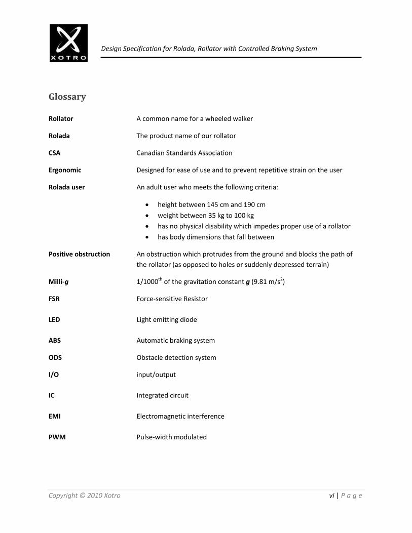
Glossary
Rollator A common name for a wheeled walker
Rolada The product name of our rollator
CSA Canadian Standards Association
Ergonomic Designed for ease of use and to prevent repetitive strain on the user
Rolada user An adult user who meets the following criteria:
height between 145 cm and 190 cm
weight between 35 kg to 100 kg
has no physical disability which impedes proper use of a rollator
has body dimensions that fall between
Positive obstruction An obstruction which protrudes from the ground and blocks the path of
the rollator (as opposed to holes or suddenly depressed terrain)
Milli-g 1/1000th of the gravitation constant g (9.81 m/s2)
FSR Force-sensitive Resistor
LED Light emitting diode
ABS Automatic braking system
ODS Obstacle detection system
I/O input/output
IC Integrated circuit
EMI Electromagnetic interference
PWM Pulse-width modulated

Copyright © 2010 Xotro 1 | P a g e
Design Specification for Rolada, Rollator with Controlled Braking System
1. Introduction Rolada is a rollator that will automatically provide braking resistance if a speed limit is exceeded and while going down a slope to support a user which has body dimensions that fall between those of the 5th percentile female and the 95th percentile male. Rolada senses the slope angle by using an accelerometer and wheel speeds using encoders. Furthermore, Rolada is equipped with ultrasonic sensors to detect obstacles and nighttime LED lighting for improved visibility. Rolada has a frame that provides much more legroom for the user and has a door wheel which slides on doors, allowing much easier access to doorways. Our goal is to create a rollator which provides unparalleled safety and comfort for elderly or injured users to have support while walking. The technical specification outlines the technical details for the design of each component of Rolada.
1.1. Scope This document describes the design of Rolada and explains how the design accomplishes the functional requirements as described in Functional Specification for Rolada, Rollator with Controlled Braking System [1]. The requirements expressed here associate solely to the preproduction model (proof-of-concept).
1.2. Intended Audience The intended audience of this document is all the members of Xotro. The design specifications will be directly referenced in the implementation of the model. Testing engineers will use the document to execute the stated test plan to check for conformity with the stated criteria of the model.
2. System Specifications Rolada will adjust the braking force of the bicycle brakes on both wheels. Rolada will perform the adjustments automatically if the switch for the ABS function is turned on. The accelerometer will provide tilt readings which the rollator will use to adjust the braking force. Brakes will also be engaged according to the speed limit, which has a manual user setting (a knob allows the user to select 3 different speeds or turn off the speed limit). Rolada will emit “beeps” through its speaker if a positive obstruction is detected by the ultrasonic sensors. In terms of the automatic braking adjustment, the system should adjust to a certain braking force in response to a change in slope and speed within 10 seconds, unless another change is detected. The system should respond to a manual change to the speed limit within 10 seconds.

Copyright © 2010 Xotro 2 | P a g e
Design Specification for Rolada, Rollator with Controlled Braking System
3. Overall System Design This section describes the high-level design of Rolada. The specification that applies to all parts of Rolada will be provided within this section. Design details pertaining to specific functional parts of Rolada will be explained in their respective sections later.
3.1. High-level System Design This section presents a high-level overview of the entire system design of Rolada. The system block diagram is illustrated in figure 2. The inputs of the system include user speed limit control knob (rotary switch), analog and digital sensors, wheel encoder and an input switch (on/off switch for obstacle detection). The microcontroller is capable of reading PWM signals from the accelerometer and wheel encoders, as well as the high/low signals of the switches. Furthermore, the microcontroller has analog reading pins which have an analog-to-digital converter built-in, allowing the reading of analog sensors. Thus, input signal conditioning applies only to the force sensitive resistors. The force-sensitive resistors require a voltage divider and op-amp circuit, as shown in figure 1, where RM is a resistor.
Figure 1 - Voltage divider circuit for FSRs [1]

Copyright © 2010 Xotro 3 | P a g e
Design Specification for Rolada, Rollator with Controlled Braking System
Figure 2 - System Block Diagram
Inputs
Analog Sensors
• Force sensitive resistors (FSRs)
Digital Transducers
• Accelerometer
• Wheel Encoders
• Ultrasonic Sensors
Input speed rotary switch
Input switch
Ambient Light Sensor
Input Signal Conditioning
Voltage Divider Circuit + Opamp
Signal Processing
Microcontroller
Transistor and circuitry
Output Signal
Conditioning
Motor Drivers
Outputs
Stepper Linear Actuators
Buzzer
Light Emitting Diodes

Copyright © 2010 Xotro 4 | P a g e
Design Specification for Rolada, Rollator with Controlled Braking System
The ambient light sensor controls the LEDs directly without the microcontroller by using transistors and resistors in a circuit. The LED circuit also has an override switch to manually turn the system off. The output of the microcontroller requires motor drivers to drive the motors. The motor drivers will have H-bridges with built in current sensors and step lines for the PWM signals. The motor driver will provide 6V to the motors. The motor drivers will also have a direction control line for the microcontroller to control its direction of travel. The microcontroller can generate a square wave signal to the buzzer so an oscillator circuit is not necessary to create a pulsed signal. The microcontroller will be directly connected to the buzzer to produce beeping sounds.
3.2. Sensor Placement The following types of sensors will be used in Rolada:
- Force sensitive resistors - Encoders - Accelerometer - Ultrasonic sensors - Ambient light sensor
Figure 3 shows the placement of the above sensors on the rollator. For sensing braking force, strain gages were considered but force sensitive resistors are selected due to its cost-effectiveness and ease of mounting for our application. For distance sensors, we have considered using infrared sensor modules. The infrared sensors are modulated to prevent interference from ambient light. Ultrasonic sensors were selected in the end because of its comparatively lower power consumption and wider detection angle. Ultrasonic sensors are also resistant to interference and can detect objects at closer range than infrared sensors. Encoders are selected as the method of measuring wheel velocity because of its simplicity and light weight. The method of integrating the measurements from an accelerometer to calculate the velocity does not seem to provide reliable results as it is subject to error and drifting. To determine the angle of tilt of the rollator, an accelerometer will be deployed. Accelerometers are readily available and have very low power consumption. An advantage of accelerometer measurements is that it can determine its angle of tilt when starting at any angle, as opposed to a gyroscope which requires the knowledge of its initial angle when starting up.

Copyright © 2010 Xotro 5 | P a g e
Design Specification for Rolada, Rollator with Controlled Braking System
For detecting the level of ambient light, we will use a photo-resistor based circuit. Photo-resistors based sensors are low cost and easily obtainable. Although the sensor does not have the rapid performance of photodiodes or phototransistors, it is more than sufficient for our application.
Figure 3 - Sensors on the rollator
3.3. Electrical System The Rolada will have a single power source. The battery will be 6V and is rechargeable. All components will draw power from this battery source. The Arduino microcontrollers will regulate the voltage from the 6V battery through its internal voltage regulator. The Motor driver circuit will also regulate the voltage from the 6V battery source. The Motor driver circuit can safely handle up to 750 mA of current and 6V - 30V. The Arduino can safely handle an input voltage of 7V - 12V.

Copyright © 2010 Xotro 6 | P a g e
Design Specification for Rolada, Rollator with Controlled Braking System
Figure 4 - Electrical connections of the system
3.3.1. Power Supply (battery)
The following battery is required for full functionality of Rolada:
- Maximum current: 750 mA
- Supply voltage: 6V DC
- Number of connectors: 1
- Capacity: 4000 mAh
3.3.2. Noise Considerations Long wires are required to link the sensors to the microcontrollers; as a result, there will be
electromagnetic interference (EMI). We will attempt to reduce any noise and distortion by the follow
methods:
- Utilizing sufficient signal strength - Choosing high quality wires to minimize noise - Program microcontroller to sample multiple times to compensate for interference - Routing wires efficiently to minimize length - Solder wires and pins properly to ensure reliability
Battery 6V
Photo-resistor
LEDs
motor driverStepper linear
actuators
Arduino Microcontroller
Force Sensitive Resistors
Accelerometer
Ultrasonic sensors
Buzzer
Optical Encoder

Copyright © 2010 Xotro 7 | P a g e
Design Specification for Rolada, Rollator with Controlled Braking System
3.3.3. Safety Considerations The following precautions are in placed to prevent the Rolada electronic components from damage and inflicting damage to developers and users.
- Proper choice of battery is considered - Heatsinks are used as necessary on electronic components - Wires are properly insulated - Sensitive electronics are shielded
4. Automatic Braking System Design
The automatic braking system or ABS is an electro-mechanical design that consists of the following
electronics components, a dual-axis accelerometer, microcontroller, motor drivers, force sensor and
speed sensor. The mechanical components will be the rollator’s integrated manual wheel locks and
plastic gears. The electro-mechanical components are hybrid linear actuators and a speed limit control
knob. The ABS will be driven by several parameters coming from the sensors (accelerometer, force
sensor and speed sensor) and the speed limit control knob. The parameters from the sensors alone are
the rollator’s average speed, tilt angle, and actual braking force; they are to be compared with the user’s
selected speed limit. The parameters are input into the microcontroller to actuate the mechanical
braking mechanism on the rear wheels accordingly. The presence of the three sensors forms several
feedback paths for the ABS.
Figure 5 - ABS block diagram

Copyright © 2010 Xotro 8 | P a g e
Design Specification for Rolada, Rollator with Controlled Braking System
4.1. Accelerometer
The objective of the accelerometer is to provide the ABS with the rollator’s current tilt angle relative to a
reference axis. Because the chosen accelerometer is dual axis, it outputs acceleration in both the x-axis
and y-axis. The accelerometer will be connected to a section of the digital I/O pins of the microcontroller.
Hence, the accelerometer provides a feedback path for the ABS.
As for the tilt angle measurements, the parameter of interest is the rollator’s forward incline angle
relative to the reference axis. The reference axis corresponds to the null output of the accelerometer.
The accelerometer will be positioned on the rollator’s frame such that one of its two axes will be parallel
to the rollator’s forward moving direction and the sensing plane formed by the two axes will be parallel
to the ground plane. The tilt angle θTilt due to driving the rollator on an inclined surface and the
accelerometer’s output a in mg are related by the following equation.
±𝜃𝑇𝑖𝑙𝑡 = sin−1 ±𝑎
1000 (1)
The intended operational frequency of the accelerometer would be 10 Hz.
4.2. Speed Sensor
The speed sensor is used to measure the speed of the rollator and it is another feedback path for the
ABS. It is an optical incremental encoder with its rotational axis indirectly coupled to one of the rear
wheel’s rotational axis. A pair of identical thin gears with gear ratio of 1:1 will be used to couple the two
rotational axes indirectly. The encoder will output a pair of quadrature signals in the form of pulses and
a reference signal for tracking revolutions. These three output signals are sent to the microcontroller’s
digital I/O pins as the current angular displacement and the zero angle reference. The current angular
displacement relative to the referenced zero angle is interpreted by counting the number of rising or
falling edge of either of the two quadrature signals. From the microcontroller, the angular displacement
θ is then converted to linear displacement x by relating the accumulated number of revolutions n, the
current angular displacement relative to the reference angle, the total number of windows on the
encoder code wheel θTotal and the circumference of the wheel C as follows.
𝑥 = 𝑛 +𝜃
𝜃𝑇𝑜𝑡𝑎𝑙 𝐶 (2)

Copyright © 2010 Xotro 9 | P a g e
Design Specification for Rolada, Rollator with Controlled Braking System
By fixing the speed sampling time ∆t, the average linear speed of the rollator v can be computed.
𝑣 =
𝑥
∆𝑡=
𝑛 +𝜃
𝜃𝑇𝑜𝑡𝑎𝑙 𝐶
∆𝑡
(3)
The average linear speed is then compared to the user’s chosen speed limit. After each speed sampling
time, the accumulated number of revolutions will be reset to zero to avoid overlapping accumulation
among consecutive speed samples. The encoder is intended to have 15 Hz. The direction of the average
velocity can be found by comparing two successive output binary values from the encoder to check if
the wheel is rotating in the clockwise or counter clockwise direction. As long as the rotational axis of the
encoder is parallel to the wheel’s rotational axis, then a clockwise or counter clockwise rotation on the
rear wheels represent a forward or backward movement of the rollator.
4.3 Force Sensing Resistor
The FSR is used to determine the actual amount of brake force exerted onto the rollator’s rear wheels.
By doing so, FSR provides another feedback path for the ABS. The reason why FSR is used as the force
sensor is that it is small and thin, allowing it to be easily positioned between the brake pad and the
brake clamp of the mechanical braking mechanism. The FSR input is depended on the force exerted by
the brake pad. The unit measurement of the FSR is ohm which implies it is similar in nature to a
potentiometer. The resistance ranges from essentially infinity down to 2kΩ as external force is applied
to the FSR. The FSR is connected to a calibrating resistor RM to form a voltage divider, and an
operational amplifier (op-amp) is used to buffer this voltage divider to the microcontroller. Then the
microcontroller translates the measurement of voltage from the op-amp into a force unit measurement
of kilo-g using the plot of figure 6. The graph below shows the force-voltage profile of the circuit
consisting of the voltage divider and op-amp. The result of the measurement of force will then be used
to properly adjust the braking force on the wheel.

Copyright © 2010 Xotro 10 | P a g e
Design Specification for Rolada, Rollator with Controlled Braking System
Figure 6 - Force-Voltage characteristic graph of a voltage divider circuit
4.4 Speed Limit Control Knob
The speed limit control knob is designed to allow users to choose a selection of discrete speed limit
values for the rollator on inclined surface. If the chosen speed limit is exceeded, the ABS will apply some
braking to the rear wheels according to the tilt angle, slowing down the rollator. The speed limit control
knob is constructed by enclosing a single-pole-multiple-throw rotary switch with a plastic case. To
regulate the signal from the rotary switch, one of the digital I/O pins will be connected to the input of
the rotary switch. This can avoid external regulating circuitry for the speed limit control knob.
4.5 Microcontroller
The purpose of the microcontroller is to control the response of the ABS as known parameters are
continuously fed into the system. The controlling method of the microcontroller is similar to that of a
pure proportional controller in which the braking force is proportional to the current speed relative to
the speed limit.
The microcontroller is buffered to the accelerometer, speed sensor, force sensor, speed limit control
knob, both motor driver boards and the main power supply with voltage and/or current regulators.
From figure 5, the accelerometer, speed sensor, force sensor and speed limit control knob are the
components providing the inputs to the microcontroller. Based on these inputs, the microcontroller will
compute the corresponding actuating signals for the hybrid linear actuators and their motor drivers.
Copyright © 2010 Xotro 11 | P a g e
Design Specification for Rolada, Rollator with Controlled Braking System
Initially, the microcontroller will be predefined with a table of constants, containing the minimum
braking forces needed for the rollator relative to the intended range of tilt angles. Thus, this defined
table lists tilt angle and braking force in pairs.
The microcontroller will monitor and control the ABS by the following descriptive algorithm. Prior to any
signal conditioning, the microcontroller will first convert and process all the input parameters to
appropriate variables. The accelerometer’s dual output pulses will be translated to acceleration values
in milli-g. Similarly, the speed sensor’s output quadrature signals and reference signal will be translated
to the corresponding angular displacements in degrees. Also, the output voltage from the force sensor
will be translated to force values in kilo-g.
With the acceleration values and the angular displacements known, the average linear speed and tilt
angle can be found as described in sections 4.1 and 4.2. Next, the microcontroller will compare the
current speed with the user’s chosen speed limit. When the current speed exceeds an initial percentage
of the speed limit, the microcontroller will respond promptly by driving the motor driver and actuator to
apply a fraction of the corresponding minimum braking force on the rear wheels. This minimum braking
force chosen from the predefined constant table is based on the current tilt angle. Once the brake force
is applied to the rear wheels, the force and speed sensors will output new measurements to feed back
into the microcontroller as input parameters. At the same moment, the accelerometer, although
indirectly, will also be affected by the sudden change in speed, returning new acceleration
measurements for the microcontroller to process. Hence, these new input parameters for the
microcontroller will trigger the ABS to apply a slightly increased brake force to the rollator.
Upon successive time intervals, the microcontroller will continue to control the motor driver and
actuator to gradually increase the braking force on the rear wheels until the current speed has reached
to a peak value slightly over the speed limit. As the current speed falls, the microcontroller will signal the
motor driver and actuator to slowly reduce the braking force on the wheels until the current speed has
reached to a steady state below the selected speed limit. This gradual braking process allows a smooth
braking transition for the rollator.
4.6 Motor Driver and Hybrid Linear Actuator
The bipolar hybrid linear actuator along with the motor driver will drive and control the mechanical
braking mechanism of the ABS. The actuator is chosen because the motor itself has a prebuilt gear
mechanism that provides more holding torque and precise positioning as well as needing only a 5V
requirement.
Copyright © 2010 Xotro 12 | P a g e
Design Specification for Rolada, Rollator with Controlled Braking System
The motor driver will receive inputs from the microcontroller. The microcontroller will send commands
to the motor driver by using high and low signals in order to enable/disable the motor driver. When the
high signal occurs, it would enable the motor driver to drive the actuator and vice versa when low signal
occurs. Voltage is use as unit of measurement to read the high and low signal. The signal has a range
from minimum of zero volts or the maximum of five volts. Connected to the outputs of the motor driver
are the inputs of the actuator. As a result the actuator will be driven accordingly to the microcontroller
through the motor driver.
The actuator is connected to the cable of the pulley that controls the brake. When the actuator rotates,
it will pull the pulley causing the brake to clamp on to the rear wheels’ outer rims, stopping the rollator’s
motion. Hence, the actuator acts as a transition between electrical and mechanical system.
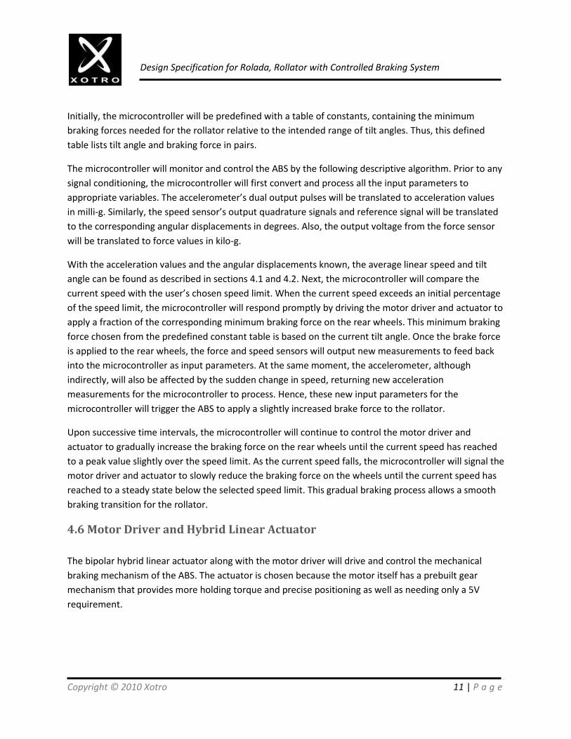
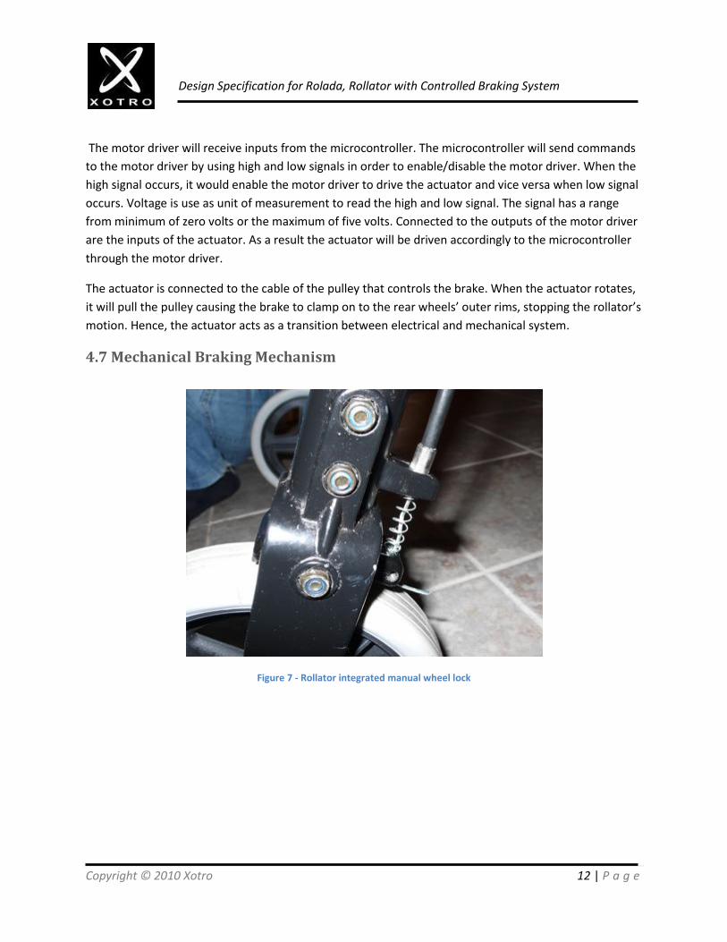
4.7 Mechanical Braking Mechanism
Figure 7 - Rollator integrated manual wheel lock

Copyright © 2010 Xotro 13 | P a g e
Design Specification for Rolada, Rollator with Controlled Braking System
Figure 8 - Rollator integrated manual wheel lock (alternate view)
The rollator’s integrated manual wheel lock as shown in figures 7 and 8 will be used as the mechanical
braking mechanism of the ABS. Because the wheel lock is already integrated on the rollator, only slight
modification to it will be needed to assemble the mechanical braking mechanism. The wheel lock will be
modified by adding a custom brake pad underneath the locking wedge and extending the back of the
locking wedge. A hole will be drilled on the extended piece of the locking wedge and the actuator will be
coupled through this hole. Since the wheel lock is designed for most rollators, its reliability guaranteed.
Also, the relatively simple pivoting mechanism of the integrated manual wheel lock allows ease in the
mechanical analysis of the ABS. Depending on the pulling force of the actuator; the wheel lock will apply
a corresponding and proportional brake force to the rollator’s rear wheels. The moment the brake pad
contacts the outer surface of the rear wheel, the force and speed sensors will generate new
measurements to feed back to the microcontroller and thus, closing the open loop of the ABS.
5. Obstacle Detection System
The obstacle detection system notifies the user of obstructions. The frequency of the buzzer beeps
changes according to the proximity of a detected obstruction.
5.1. Physical and Mechanical Design
The ultrasonic sensors are enclosed in boxes which are secured under the middle bar at the front of the
rollator using a metal bracket. This placement allows easy adjustments to the angle of the sensors to

Copyright © 2010 Xotro 14 | P a g e
Design Specification for Rolada, Rollator with Controlled Braking System
provide optimum obstacle detection performance. The sensors are connected to the microcontroller
board mounted in the middle of the same bar. The buzzer is mounted near the top of the rollator and
aimed near the direction of the user for better audibility. Figure shows the location of the sensors and
buzzer on the rollator.
5.2. Electronic Design
A switch on the rollator (also shown in figure) allows a user to turn off the obstacle detection system.
The switch is connected to the +5V on one end and to a digital pin on the microcontroller on the other
end. The microcontroller is capable of generating a pulsing square wave signal to directly drive the
buzzer; therefore an independent oscillator circuit is not necessary. The ultrasonic sensors are powered
by 5V DC output from the microcontroller. The microcontroller will activate the sensors to detect for
obstacles every 200 milliseconds. After a successful reading, the PWM pin will output pulse (every 50us
represents 1cm). The distance to the object can then be derived. The microcontroller can then vary the
beeping frequency accordingly, with more frequent sounds for closer obstruction proximity.
Figure 9 - Electrical system for obstacle detection
The logic of the program loop can be seen in the block diagram illustrated in figure 4.
Battery (6V)Microcontroller
(6V)
Ultrasonic Sensor (5V)
Ultrasonic Sensor (5V)
Buzzer (5V PWM)

Copyright © 2010 Xotro 15 | P a g e
Design Specification for Rolada, Rollator with Controlled Braking System
Figure 10 - Program loop for obstacle detection system
6. Frame
The frame of the rollator will give the user slightly more leg room, allowing easier access to door handles.
The frame will also have a door wheel attached to easily slide through a doorway.
6.1. Physical and Mechanical Design
The bar near the front of the user will be modified as shown in figure 5. As demonstrated, the bar has
been put placed further to the front to give the user more leg room while maintaining a very strong
support for the seat. The seat is folded up in the illustration.
Activate ultrasonic
sensors
Interpret PWM signal
from sensors
Set beeping interval
Beep according to
interval
Wait 200 ms

Copyright © 2010 Xotro 16 | P a g e
Design Specification for Rolada, Rollator with Controlled Braking System
Figure 11 - Rollator frame rear bar modification
The bar will be mounted in the position shown by using steel bolts and nuts to fasten it to the rear supporting bars. The bar is secured with the ends parallel to the support bars, which are at 65 degrees relative to the ground. The force on the bar when a 250 lb user sits on the seat is approximately 1108.5 N. The total shear force on all of the bolts is estimated to be 1004.67 N. The safe tensile load of a ¼” SAE steel bolt is 167.83 kg or 1646.41 N (considering the threading strength of the bolt). Thus using 4 bolts should provide adequate support for the weight of the user while sitting.
6.2. Door wheel
The door wheel allows the user to glide past a closing door easily. Figure shows the mechanical design of
the wheel.

Copyright © 2010 Xotro 17 | P a g e
Design Specification for Rolada, Rollator with Controlled Braking System
Figure 12 - Door wheels on Rolada
As shown, the wheel is mounted at the front of the rollator on top of the front wheels. The wheels have
a rubber surface and are contact-friendly to walls and doors. The wheel has a diameter of 12 cm and
rotates as it moves along a surface. The wheels are mounted near the bottom of the rollator so that it
minimizes the effect on the balance of the rollator as force is applied. It also reduces the visual
obtrusiveness of the design, compared to mounting the wheels near the handlebars.
7. Lighting System
The lighting system uses LEDs to light up the near-by area of the Rolada. With LEDs and reflective tape, it
makes Rolada be easy to be seen by other people in the dark.

Copyright © 2010 Xotro 18 | P a g e
Design Specification for Rolada, Rollator with Controlled Braking System
7.1. Physical and Mechanical Design
LEDS will be placed according to the figure below. The green circles indicate the location of LED
installment. The light sensitive resistor will be installed within the designated green circles as shown
below.
Figure 13 – Placement of the LEDs on the rollator

Copyright © 2010 Xotro 19 | P a g e
Design Specification for Rolada, Rollator with Controlled Braking System
7.2. Electronic Design
Figure 14 - Circuit schematic for lighting system
As shown in the schematic above, the light source will be an input to the system, and the LED will be the
output of the system.
The phototransistor T1 controls the LEDs on the left side of the rollator. When T1 senses no light, it will
turn on LEDs (L1, L2 and L3). On the other hand, the phototransistor T2 will control the LEDs (L4, L5 and
L6) on the right side.
7.2.1. Phototransistor
A phototransistor conducts electricity when it senses light. It is especially useful in light-sensing
applications.
When the phototransistor senses no light, it will have a large voltage across A on the schematic above.
This large voltage on A will lead to a voltage large enough to light up the LED. However, when there is a
light, the phototransistor will start to conduct, and the voltage A will be greatly reduced, therefore,
turning off the LED.
7.2.2. LED
LED is in white color, and it needs to have 3.0V – 3.4V and 20mA to light up. It is ultra bright with
15000MCD.

Copyright © 2010 Xotro 20 | P a g e
Design Specification for Rolada, Rollator with Controlled Braking System
7.2.3. Transistor
2N3904 is a typical NPN type transistor which will conduct the electricity when the voltage A reaches a
certain point higher than 0.65V – 0.85V.
7.2.4. Resistor
The resistor is needed for the voltage dropdown when the phototransistor conducts.
7.2.5. Power Source
The power will be delivered to the system from the main 6V battery pack.
7.2.6. ON/OFF Switch
ON/OFF switch will control the overall system. While it is off, it will turn off the lighting system, which
the system will not light up in the darkness. While it is on, the system will light up the Rolada when it
senses no light.
8. Conclusion
The proposed design solutions to meet the functional specifications of Rolada have been discussed in
detail in this document. During the actual development of the project, the design specifications
presented will be adhered to as much as possible in order to satisfy the functional specifications. By
executing the test plans presented in this document, we can verify that the required functionality of
Rolada will be present in the proof-of-concept model. With nearly all the necessary electronic and
mechanical components at our disposal, Team Xotro has already begun the implementation of Rolada
following the functional and design specifications.

Copyright © 2010 Xotro 21 | P a g e
Design Specification for Rolada, Rollator with Controlled Braking System
9. Appendix
The braking force needed to stop the rollator can be modeled by this simplified system
Figure 15 - Brake force analysis (model 1)
The governing equation for this system is
𝐹𝑥 = 0:
→+
𝑓𝐵𝑟𝑎𝑘𝑒 + 𝑓𝑘𝑖𝑛𝑒𝑡𝑖𝑐 − 𝐹𝑎𝑝𝑝𝑙𝑖𝑒𝑑 − 𝐹𝑔𝑟𝑎𝑣𝑖𝑡𝑦 sin𝜃 = 0
∴ 𝑓𝐵𝑟𝑎𝑘𝑒 𝜃, 𝑚𝑢𝑠𝑒𝑟 , 𝐹𝑎𝑝𝑝𝑙𝑖𝑒𝑑 = 𝐹𝑎𝑝𝑝𝑙𝑖𝑒𝑑 + 𝐹𝑔𝑟𝑎𝑣𝑖𝑡𝑦 sin𝜃 − 𝑓𝑘𝑖𝑛𝑒𝑡𝑖𝑐 = 𝐹𝑎𝑝𝑝𝑙𝑖𝑒𝑑 + 𝑚𝑟𝑜𝑙𝑙𝑎𝑡𝑜𝑟 + 𝑚𝑢𝑠𝑒𝑟 𝑔 sin𝜃
− 𝜇𝑟𝑜𝑙𝑙𝑖𝑛𝑔 𝑚𝑟𝑜𝑙𝑙𝑎𝑡𝑜𝑟 + 𝑚𝑢𝑠𝑒𝑟 𝑔 cos 𝜃 = 𝐹𝑎𝑝𝑝𝑙𝑖𝑒𝑑 + 𝑚𝑟𝑜𝑙𝑙𝑎𝑡𝑜𝑟 + 𝑚𝑢𝑠𝑒𝑟 𝑔 sin𝜃 − 𝜇𝑟𝑜𝑙𝑙𝑖𝑛𝑔 cos 𝜃

Copyright © 2010 Xotro 22 | P a g e
Design Specification for Rolada, Rollator with Controlled Braking System
Based on the governing equation shown above, the maximum and minimum necessary braking forces
are:
𝑓𝐵𝑟𝑎𝑘𝑒𝑚𝑖𝑛 𝜃 = lim
𝑚𝑢𝑠𝑒𝑟 →0; 𝐹𝑎𝑝𝑝𝑙𝑖𝑒𝑑 →0 𝐹𝑎𝑝𝑝𝑙𝑖𝑒𝑑 + 𝑚𝑟𝑜𝑙𝑙𝑎𝑡𝑜𝑟 + 𝑚𝑢𝑠𝑒𝑟 𝑔 sin𝜃 − 𝜇𝑟𝑜𝑙𝑙𝑖𝑛𝑔 cos𝜃
= lim𝐹𝑎𝑝𝑝𝑙𝑖𝑒𝑑 →0
𝐹𝑎𝑝𝑝𝑙𝑖𝑒𝑑 + 𝑔 sin𝜃 − 𝜇𝑟𝑜𝑙𝑙𝑖𝑛𝑔 cos𝜃 lim𝑚𝑢𝑠𝑒𝑟 →0
𝑚𝑟𝑜𝑙𝑙𝑎𝑡𝑜𝑟 + 𝑚𝑢𝑠𝑒𝑟
= 𝑚𝑟𝑜𝑙𝑙𝑎𝑡𝑜𝑟 𝑔 sin𝜃 − 𝜇𝑟𝑜𝑙𝑙𝑖𝑛𝑔 cos𝜃
and
𝑓𝐵𝑟𝑎𝑘𝑒𝑚𝑎𝑥 𝜃 = lim
𝑚𝑢𝑠𝑒𝑟 → 𝑚𝑢𝑠𝑒𝑟𝑚𝑎𝑥 ; 𝐹𝑎𝑝𝑝𝑙𝑖𝑒𝑑 → 𝐹𝑎𝑝𝑝𝑙𝑖𝑒𝑑
𝑚𝑎𝑥 𝐹𝑎𝑝𝑝𝑙𝑖𝑒𝑑 + 𝑚𝑟𝑜𝑙𝑙𝑎𝑡𝑜𝑟 + 𝑚𝑢𝑠𝑒𝑟 𝑔 sin𝜃 − 𝜇𝑟𝑜𝑙𝑙𝑖𝑛𝑔 cos𝜃
= lim𝐹𝑎𝑝𝑝𝑙𝑖𝑒𝑑 → 𝐹𝑎𝑝𝑝𝑙𝑖𝑒𝑑
𝑚𝑎𝑥𝐹𝑎𝑝𝑝𝑙𝑖𝑒𝑑 + 𝑔 sin𝜃 − 𝜇𝑟𝑜𝑙𝑙𝑖𝑛𝑔 cos𝜃 lim
𝑚𝑢𝑠𝑒𝑟 → 𝑚𝑢𝑠𝑒𝑟𝑚𝑎𝑥
𝑚𝑟𝑜𝑙𝑙𝑎𝑡𝑜𝑟 + 𝑚𝑢𝑠𝑒𝑟
= 𝐹𝑎𝑝𝑝𝑙𝑖𝑒𝑑
𝑚𝑎𝑥 + 𝑚𝑟𝑜𝑙𝑙𝑎𝑡𝑜𝑟 + 𝑚𝑢𝑠𝑒𝑟𝑚𝑎𝑥 𝑔 sin𝜃 − 𝜇𝑟𝑜𝑙𝑙𝑖𝑛𝑔 cos𝜃
The applied force by the user can be written as follows:
𝐹𝑎𝑝𝑝𝑙𝑖𝑒𝑑 = 𝑚𝑢𝑠𝑒𝑟 𝑑𝑣𝑎𝑝𝑝𝑙𝑖𝑒𝑑
𝑑𝑡
where the applied speed is
𝑣𝑎𝑝𝑝𝑙𝑖𝑒𝑑 = 𝑣0 + 𝛿𝑣
Assuming there is barely any variation in the user’s applied speed, that is the applied speed is almost
constant. Then the applied force is
𝐹𝑎𝑝𝑝𝑙𝑖𝑒𝑑 ≅ 𝑚𝑢𝑠𝑒𝑟
𝑑
𝑑𝑡 lim𝛿𝑣→0
𝑣0 + 𝛿𝑣
= 𝑚𝑢𝑠𝑒𝑟 𝑑𝑣0
𝑑𝑡
= 𝑚𝑢𝑠𝑒𝑟 0 = 0

Copyright © 2010 Xotro 23 | P a g e
Design Specification for Rolada, Rollator with Controlled Braking System
Therefore, the maximum and minimum braking forces needed to stop the rollator given the user is
driving it at near constant speed are
𝑓𝐵𝑟𝑎𝑘𝑒𝑚𝑖𝑛 𝜃 = 𝑚𝑟𝑜𝑙𝑙𝑎𝑡𝑜𝑟 𝑔 sin𝜃 − 𝜇𝑟𝑜𝑙𝑙𝑖𝑛𝑔 cos𝜃
and
𝑓𝐵𝑟𝑎𝑘𝑒𝑚𝑎𝑥 𝜃 ≅ 𝑚𝑟𝑜𝑙𝑙𝑎𝑡𝑜𝑟 + 𝑚𝑢𝑠𝑒𝑟
𝑚𝑎𝑥 𝑔 sin𝜃 − 𝜇𝑟𝑜𝑙𝑙𝑖𝑛𝑔 cos𝜃
Hence, the rollator system will require to have the following braking force constraint
𝑚𝑟𝑜𝑙𝑙𝑎𝑡𝑜𝑟 𝑔 sin𝜃 − 𝜇𝑟𝑜𝑙𝑙𝑖𝑛𝑔 cos𝜃 ≤ 𝑓𝐵𝑟𝑎𝑘𝑒 𝜃, 𝑚𝑢𝑠𝑒𝑟
≤ 𝑚𝑟𝑜𝑙𝑙𝑎𝑡𝑜𝑟 + 𝑚𝑢𝑠𝑒𝑟𝑚𝑎𝑥 𝑔 sin𝜃 − 𝜇𝑟𝑜𝑙𝑙𝑖𝑛𝑔 cos𝜃
Based on this overall braking force constraint, the actual braking force required for each of the two rear
wheel can be written as
𝑓𝐵𝑟𝑎𝑘𝑒 𝜃, 𝑚𝑢𝑠𝑒𝑟 = 𝑓𝐿𝑒𝑓𝑡 _𝑤𝑒𝑒𝑙 + 𝑓𝑅𝑖𝑔𝑡_𝑤𝑒𝑒𝑙
Assuming that the overall braking force distributed to both rear wheels is linear, then the braking force
of the left and right wheels can be individually defined as a fraction of the overall braking force.
Let
𝑓𝐿𝑒𝑓𝑡 _𝑤𝑒𝑒𝑙 = 𝛼1𝑓𝐵𝑟𝑎𝑘𝑒 𝜃, 𝑚𝑢𝑠𝑒𝑟 ; 0 < 𝛼1 < 1
and
𝑓𝑅𝑖𝑔𝑡_𝑤𝑒𝑒𝑙 = 𝛼2𝑓𝐵𝑟𝑎𝑘𝑒 𝜃, 𝑚𝑢𝑠𝑒𝑟 ; 0 < 𝛼2 < 1
so that
𝛼1 + 𝛼2 = 1
Thus,
𝑓𝐵𝑟𝑎𝑘𝑒 𝜃, 𝑚𝑢𝑠𝑒𝑟 = 𝑓𝐿𝑒𝑓𝑡 _𝑤𝑒𝑒𝑙 + 𝑓𝑅𝑖𝑔𝑡_𝑤𝑒𝑒𝑙
= 𝛼1𝑓𝐵𝑟𝑎𝑘𝑒 𝜃, 𝑚𝑢𝑠𝑒𝑟 + 𝛼2𝑓𝐵𝑟𝑎𝑘𝑒 𝜃, 𝑚𝑢𝑠𝑒𝑟 = 𝛼1 + 𝛼2 𝑓𝐵𝑟𝑎𝑘𝑒 𝜃, 𝑚𝑢𝑠𝑒𝑟 = 𝑓𝐵𝑟𝑎𝑘𝑒 𝜃, 𝑚𝑢𝑠𝑒𝑟

Copyright © 2010 Xotro 24 | P a g e
Design Specification for Rolada, Rollator with Controlled Braking System
Hence, in the case of the left rear wheel, the braking force needed to stop the wheel is
𝑓𝐿𝑒𝑓𝑡 _𝑤𝑒𝑒𝑙 = 𝛼1𝑓𝐵𝑟𝑎𝑘𝑒 𝜃, 𝑚𝑢𝑠𝑒𝑟
When the modified wheel lock makes contact with the rear wheel’s outer surface, a portion of the brake
pad will be tangent to the wheel’s surface. Therefore, the braking force needed by the modified wheel
lock can be modeled by the following figure.
Figure 16 - Brake force analysis (model 2)
From figure 16, the distance from the center of the wedge to Fwedge is d1, the distance from the center of
the wedge to Force is d2, and the normal force of the locking wedge is related to the braking force by the
following
𝑓𝐿𝑒𝑓𝑡 _𝑤𝑒𝑒𝑙 = 𝐹𝐵𝑟𝑎𝑘𝑒 = 𝜇𝑘𝑖𝑛𝑒𝑡𝑖𝑐 _𝑜𝑓 _𝑤𝑒𝑒𝑙𝐹𝑤𝑒𝑑𝑔𝑒
or
𝐹𝑤𝑒𝑑𝑔𝑒 = 𝛼1
𝜇𝑘𝑖𝑛𝑒𝑡𝑖𝑐 _𝑜𝑓 _𝑤𝑒𝑒𝑙 𝑓𝐵𝑟𝑎𝑘𝑒 𝜃, 𝑚𝑢𝑠𝑒𝑟
Also, the pulling force of the actuator needed to apply the corresponding braking force is computed as
follows.

Copyright © 2010 Xotro 25 | P a g e
Design Specification for Rolada, Rollator with Controlled Braking System
𝑀𝑤𝑒𝑑𝑔𝑒 = 0:
𝑐𝑐𝑤 +
𝐹𝑝𝑢𝑙𝑙 = 𝐹𝑜𝑟𝑐𝑒
𝐹𝑝𝑢𝑙𝑙 𝑑2 cos 𝑏 − 𝐹𝑤𝑒𝑑𝑔𝑒 cos𝑏 𝑑1 cos𝑏 − 𝐹𝑤𝑒𝑑𝑔𝑒 sin𝑏 𝑑1 sin𝑏 = 0
which yields
𝐹𝑝𝑢𝑙𝑙 𝑑2 cos 𝑏 = 𝐹𝑤𝑒𝑑𝑔𝑒 𝑑1 cos2 𝑏 + 𝐹𝑤𝑒𝑑𝑔𝑒 𝑑1 sin2 𝑏
= 𝐹𝑤𝑒𝑑𝑔𝑒 𝑑1 𝑐𝑜𝑠2 𝑏 + 𝑠𝑖𝑛2 𝑏
= 𝐹𝑤𝑒𝑑𝑔𝑒 𝑑1
∴ 𝐹𝑝𝑢𝑙𝑙 = 𝑑1
𝑑2 𝑐𝑜𝑠 𝑏 𝐹𝑤𝑒𝑑𝑔𝑒
= 𝑑1
𝑑2 𝑐𝑜𝑠 𝑏
𝛼1
𝜇𝑘𝑖𝑛𝑒𝑡𝑖𝑐 _𝑜𝑓 _𝑤𝑒𝑒𝑙 𝑓𝐵𝑟𝑎𝑘𝑒 𝜃, 𝑚𝑢𝑠𝑒𝑟
Therefore, the range of pulling force of the left actuator is
𝑑1𝛼1𝑚𝑟𝑜𝑙𝑙𝑎𝑡𝑜𝑟 𝑔 sin𝜃 − 𝜇𝑟𝑜𝑙𝑙𝑖𝑛𝑔 cos𝜃
𝑑2 𝑐𝑜𝑠 𝑏 𝜇𝑘𝑖𝑛𝑒𝑡𝑖𝑐 _𝑜𝑓 _𝑤𝑒𝑒𝑙≤ 𝐹𝑝𝑢𝑙𝑙 _𝑙𝑒𝑓𝑡
≤𝑑1𝛼1𝑔 𝑚𝑟𝑜𝑙𝑙𝑎𝑡𝑜𝑟 + 𝑚𝑢𝑠𝑒𝑟
𝑚𝑎𝑥 𝑠𝑖𝑛 𝜃 − 𝜇𝑟𝑜𝑙𝑙𝑖𝑛𝑔 𝑐𝑜𝑠 𝜃
𝑑2 𝑐𝑜𝑠 𝑏 𝜇𝑘𝑖𝑛𝑒𝑡𝑖𝑐 _𝑜𝑓_𝑤𝑒𝑒𝑙
Similarly, the range of pulling force of the right actuator is
𝑑1𝛼2𝑚𝑟𝑜𝑙𝑙𝑎𝑡𝑜𝑟 𝑔 sin𝜃 − 𝜇𝑟𝑜𝑙𝑙𝑖𝑛𝑔 cos𝜃
𝑑2 𝑐𝑜𝑠 𝑏 𝜇𝑘𝑖𝑛𝑒𝑡𝑖𝑐 _𝑜𝑓 _𝑤𝑒𝑒𝑙≤ 𝐹𝑝𝑢𝑙𝑙 _𝑟𝑖𝑔𝑡
≤𝑑1𝛼2𝑔 𝑚𝑟𝑜𝑙 𝑙𝑎𝑡𝑜𝑟 + 𝑚𝑢𝑠𝑒𝑟
𝑚𝑎𝑥 𝑠𝑖𝑛 𝜃 − 𝜇𝑟𝑜𝑙𝑙𝑖𝑛𝑔 𝑐𝑜𝑠 𝜃
𝑑2 𝑐𝑜𝑠 𝑏 𝜇𝑘𝑖𝑛𝑒𝑡𝑖𝑐 _𝑜𝑓_𝑤𝑒𝑒𝑙

Copyright © 2010 Xotro 26 | P a g e
Design Specification for Rolada, Rollator with Controlled Braking System
10. References
[1] A. E. Chapman. (2008). Biomechanical Analysis of Fundamental Human Movements. (1st edition). [Online]. Available: http://books.google.ca/books?id=YqxDzfyr3k4C&lpg=PA104&ots=3eK66H1Izn&dq=walking%20downhill %20stress&pg=PA104#v=onepage&q=walking%20downhill%20stress&f=false [Accessed February 1, 2010]. [2] Canadian Standards Association International, CAN/CSA-Z412-M00 – Guideline on Office Ergonomics. Toronto: Canadian Standards Association, 2000. [3] A. Arnold. KIN 180. Class Lecture, Topic: “Office Ergonomics.” AQ 5034, Faculty of Kinesiology, Simon Fraser University, Burnaby, British Columbia, Nov. 10, 2008.