Embed Size (px)
Citation preview
3135
Twenty-Seventh Symposium (International) on Combustion/The Combustion Institute, 1998/pp. 3135–3146
THE SCIENCE AND TECHNOLOGY OF COMBUSTION IN HIGHLYPREHEATED AIR
MASASHI KATSUKI1 and TOSHIAKI HASEGAWA2
1Department of Mechanical Engineering
Osaka University
2-1 Yamada-oka, Suita, Osaka 565-0871, Japan2Nippon Furnace Kogyo Kaisha Ltd.
1-53 2-Chome, Shitte, Tsurumi, Yokohama 230-8666, Japan
Recent advances in heat-recirculating combustion in industrial furnaces, particularly of the alternatingflow type, are reviewed. A large amount of waste heat can be recovered by this type of system. Highlypreheated combustion air, typically above 1300 K, is easily obtained due to advanced design and materialsemployed. Although preheated air combustion generally produces high nitric oxide emissions, it has beenused to generate high-temperature flames for some special applications. The energy saving achieved si-multaneously by heat recirculation has become more attractive from an ecological point of view. However,to enjoy the energy saving brought by a high rate of heat recirculation by applying highly preheated aircombustion to generic industrial furnaces, a reduction of nitric oxide emission is required. The possibilityof low nitric oxide emission from highly preheated air combustion is intensively discussed. Dilution of theair with burned gases and combustion occurring in air with low oxygen concentration are shown to beindispensable factors in realizing low nitric oxide emissions. This has led to advanced furnace technology.
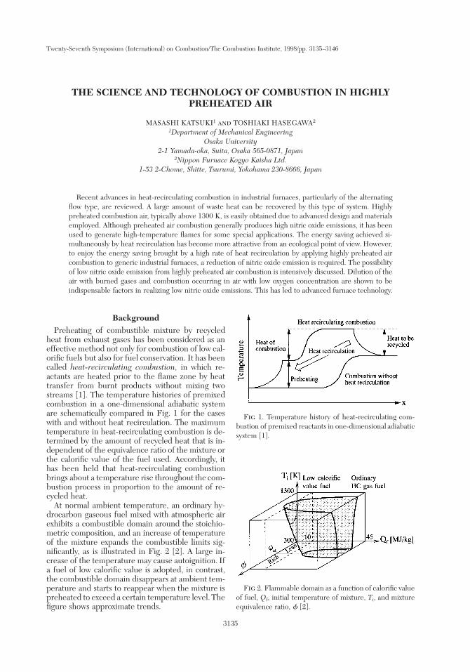
Fig 1. Temperature history of heat-recirculating com-bustion of premixed reactants in one-dimensional adiabaticsystem [1].
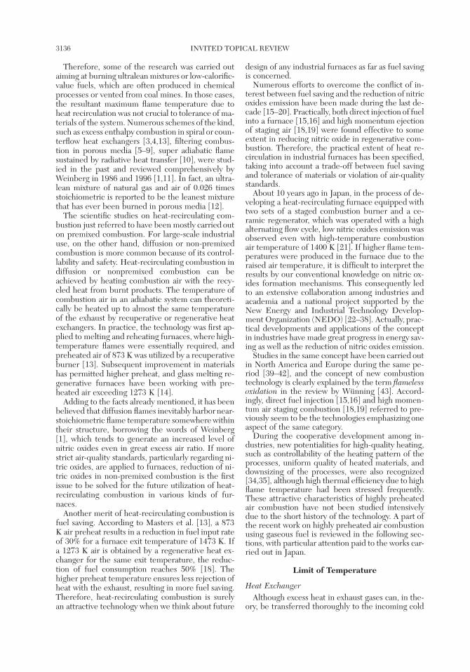
Fig 2. Flammable domain as a function of calorific valueof fuel, Qf, initial temperature of mixture, Ti, and mixtureequivalence ratio, f [2].
Background
Preheating of combustible mixture by recycledheat from exhaust gases has been considered as aneffective method not only for combustion of low cal-orific fuels but also for fuel conservation. It has beencalled heat-recirculating combustion, in which re-actants are heated prior to the flame zone by heattransfer from burnt products without mixing twostreams [1]. The temperature histories of premixedcombustion in a one-dimensional adiabatic systemare schematically compared in Fig. 1 for the caseswith and without heat recirculation. The maximumtemperature in heat-recirculating combustion is de-termined by the amount of recycled heat that is in-dependent of the equivalence ratio of the mixture orthe calorific value of the fuel used. Accordingly, ithas been held that heat-recirculating combustionbrings about a temperature rise throughout the com-bustion process in proportion to the amount of re-cycled heat.
At normal ambient temperature, an ordinary hy-drocarbon gaseous fuel mixed with atmospheric airexhibits a combustible domain around the stoichio-metric composition, and an increase of temperatureof the mixture expands the combustible limits sig-nificantly, as is illustrated in Fig. 2 [2]. A large in-crease of the temperature may cause autoignition. Ifa fuel of low calorific value is adopted, in contrast,the combustible domain disappears at ambient tem-perature and starts to reappear when the mixture ispreheated to exceed a certain temperature level. Thefigure shows approximate trends.
3136 INVITED TOPICAL REVIEW
Therefore, some of the research was carried outaiming at burning ultralean mixtures or low-calorific-value fuels, which are often produced in chemicalprocesses or vented from coal mines. In those cases,the resultant maximum flame temperature due toheat recirculation was not crucial to tolerance of ma-terials of the system. Numerous schemes of the kind,such as excess enthalpy combustion in spiral or coun-terflow heat exchangers [3,4,13], filtering combus-tion in porous media [5–9], super adiabatic flamesustained by radiative heat transfer [10], were stud-ied in the past and reviewed comprehensively byWeinberg in 1986 and 1996 [1,11]. In fact, an ultra-lean mixture of natural gas and air of 0.026 timesstoichiometric is reported to be the leanest mixturethat has ever been burned in porous media [12].
The scientific studies on heat-recirculating com-bustion just referred to have been mostly carried outon premixed combustion. For large-scale industrialuse, on the other hand, diffusion or non-premixedcombustion is more common because of its control-lability and safety. Heat-recirculating combustion indiffusion or nonpremixed combustion can beachieved by heating combustion air with the recy-cled heat from burnt products. The temperature ofcombustion air in an adiabatic system can theoreti-cally be heated up to almost the same temperatureof the exhaust by recuperative or regenerative heatexchangers. In practice, the technology was first ap-plied to melting and reheating furnaces, where high-temperature flames were essentially required, andpreheated air of 873 K was utilized by a recuperativeburner [13]. Subsequent improvement in materialshas permitted higher preheat, and glass melting re-generative furnaces have been working with pre-heated air exceeding 1273 K [14].
Adding to the facts already mentioned, it has beenbelieved that diffusion flames inevitably harbor near-stoichiometric flame temperature somewhere withintheir structure, borrowing the words of Weinberg[1], which tends to generate an increased level ofnitric oxides even in great excess air ratio. If morestrict air-quality standards, particularly regarding ni-tric oxides, are applied to furnaces, reduction of ni-tric oxides in non-premixed combustion is the firstissue to be solved for the future utilization of heat-recirculating combustion in various kinds of fur-naces.
Another merit of heat-recirculating combustion isfuel saving. According to Masters et al. [13], a 873K air preheat results in a reduction in fuel input rateof 30% for a furnace exit temperature of 1473 K. Ifa 1273 K air is obtained by a regenerative heat ex-changer for the same exit temperature, the reduc-tion of fuel consumption reaches 50% [18]. Thehigher preheat temperature ensures less rejection ofheat with the exhaust, resulting in more fuel saving.Therefore, heat-recirculating combustion is surelyan attractive technology when we think about future
design of any industrial furnaces as far as fuel savingis concerned.
Numerous efforts to overcome the conflict of in-terest between fuel saving and the reduction of nitricoxides emission have been made during the last de-cade [15–20]. Practically, both direct injection of fuelinto a furnace [15,16] and high momentum ejectionof staging air [18,19] were found effective to someextent in reducing nitric oxide in regenerative com-bustion. Therefore, the practical extent of heat re-circulation in industrial furnaces has been specified,taking into account a trade-off between fuel savingand tolerance of materials or violation of air-qualitystandards.
About 10 years ago in Japan, in the process of de-veloping a heat-recirculating furnace equipped withtwo sets of a staged combustion burner and a ce-ramic regenerator, which was operated with a highalternating flow cycle, low nitric oxides emission wasobserved even with high-temperature combustionair temperature of 1400 K [21]. If higher flame tem-peratures were produced in the furnace due to theraised air temperature, it is difficult to interpret theresults by our conventional knowledge on nitric ox-ides formation mechanisms. This consequently ledto an extensive collaboration among industries andacademia and a national project supported by theNew Energy and Industrial Technology Develop-ment Organization (NEDO) [22–38]. Actually, prac-tical developments and applications of the conceptin industries have made great progress in energy sav-ing as well as the reduction of nitric oxides emission.
Studies in the same concept have been carried outin North America and Europe during the same pe-riod [39–42], and the concept of new combustiontechnology is clearly explained by the term flamelessoxidation in the review by Wunning [43]. Accord-ingly, direct fuel injection [15,16] and high momen-tum air staging combustion [18,19] referred to pre-viously seem to be the technologies emphasizing oneaspect of the same category.
During the cooperative development among in-dustries, new potentialities for high-quality heating,such as controllability of the heating pattern of theprocesses, uniform quality of heated materials, anddownsizing of the processes, were also recognized[34,35], although high thermal efficiency due to highflame temperature had been stressed frequently.These attractive characteristics of highly preheatedair combustion have not been studied intensivelydue to the short history of the technology. A part ofthe recent work on highly preheated air combustionusing gaseous fuel is reviewed in the following sec-tions, with particular attention paid to the works car-ried out in Japan.
Limit of Temperature
Heat Exchanger
Although excess heat in exhaust gases can, in the-ory, be transferred thoroughly to the incoming cold
COMBUSTION IN HIGHLY PREHEATED AIR 3137
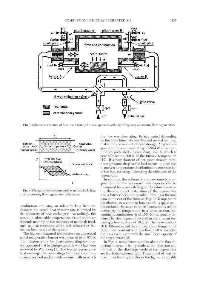
Fig 3. Schematic structure of heat-recirculating furnace operated with high-frequency alternating flow regenerators.
Fig 4. Change of temperature profile and available heatin an alternating flow regenerator (schematic).
combustion air using an infinitely long heat ex-changer, the actual heat transfer rate is limited bythe geometry of heat exchangers. Accordingly, themaximum obtainable temperature of combustion airdepends not only on the tolerance of materials used,such as heat-resistance alloys and refractories butalso on heat losses of the system.
The highest measured temperature on a practicalmetal recuperative burner was reported to be 873 K[13]. Regenerators for heat-recirculating combus-tion appeared first in Europe, and this work has beenreviewed by Weinberg [1]. The typical regenerativeheat exchanger for preheating of combustion air wasa container bed packed with ceramic balls in which
the flow was alternating. Its size varied dependingon the cycle time between 30 s and several minutes,that is, on the amount of heat storage. A typical re-generator for a nominal rating of 586-kW burner canproduce preheated air exceeding 1273 K, which isgenerally within 300 K of the furnace temperature[17]. If a flow shortcut of hot gases through mini-mum pressure drop in the bed occurs, it gives riseto uneven temperature distribution in a cross sectionof the bed, resulting in lowering the efficiency of theregenerator.
In contrast, the volume of a honeycomb-type re-generator for the necessary heat capacity can beminimized because of its large surface-to-volume ra-tio; thereby, direct installation of the regeneratorinto a burner becomes possible, forming a thermaldam at the exit of the furnace (Fig. 3). Temperaturedistribution in a ceramic honeycomb is quasi-one-dimensional, because ceramic honeycombs assureuniformity of temperature in a cross section. Ac-cordingly, combustion air of 1570 K was actually ob-tained by this regenerative system for a mean fur-nace gas temperature of 1623 K. That is only about50 K difference, and the combustion air temperaturewas almost constant with less than a 50 K variationduring a cycle, even with the small heat capacity ofthe regenerator [35].
In Fig. 4, temperature profiles along the flow di-rection in ceramic honeycombs at both the start andthe end of the discharge mode of the regeneratorare illustrated schematically. The amount of heat be-tween two limiting profiles in the figure is available
3138 INVITED TOPICAL REVIEW
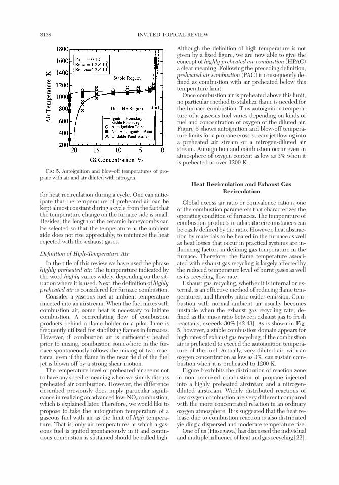
Fig 5. Autoignition and blow-off temperatures of pro-pane with air and air diluted with nitrogen.
for heat recirculation during a cycle. One can antic-ipate that the temperature of preheated air can bekept almost constant during a cycle from the fact thatthe temperature change on the furnace side is small.Besides, the length of the ceramic honeycombs canbe selected so that the temperature at the ambientside does not rise appreciably, to minimize the heatrejected with the exhaust gases.
Definition of High-Temperature Air
In the title of this review we have used the phrasehighly preheated air. The temperature indicated bythe word highly varies widely, depending on the sit-uation where it is used. Next, the definition of highlypreheated air is considered for furnace combustion.
Consider a gaseous fuel at ambient temperatureinjected into an airstream. When the fuel mixes withcombustion air, some heat is necessary to initiatecombustion. A recirculating flow of combustionproducts behind a flame holder or a pilot flame isfrequently utilized for stabilizing flames in furnaces.However, if combustion air is sufficiently heatedprior to mixing, combustion somewhere in the fur-nace spontaneously follows the mixing of two reac-tants, even if the flame in the near field of the fueljet is blown off by a strong shear motion.
The temperature level of preheated air seems notto have any specific meaning when we simply discusspreheated air combustion. However, the differencedescribed previously does imply particular signifi-cance in realizing an advanced low-NOx combustion,which is explained later. Therefore, we would like topropose to take the autoignition temperature of agaseous fuel with air as the limit of high tempera-ture. That is, only air temperatures at which a gas-eous fuel is ignited spontaneously in it and contin-uous combustion is sustained should be called high.
Although the definition of high temperature is notgiven by a fixed figure, we are now able to give theconcept of highly preheated air combustion (HPAC)a clear meaning. Following the preceding definition,preheated air combustion (PAC) is consequently de-fined as combustion with air preheated below thistemperature limit.
Once combustion air is preheated above this limit,no particular method to stabilize flame is needed forthe furnace combustion. This autoignition tempera-ture of a gaseous fuel varies depending on kinds offuel and concentration of oxygen of the diluted air.Figure 5 shows autoignition and blow-off tempera-ture limits for a propane cross-stream jet flowing intoa preheated air stream or a nitrogen-diluted airstream. Autoignition and combustion occur even inatmosphere of oxygen content as low as 3% when itis preheated to over 1200 K.
Heat Recirculation and Exhaust GasRecirculation
Global excess air ratio or equivalence ratio is oneof the combustion parameters that characterizes theoperating condition of furnaces. The temperature ofcombustion products in adiabatic circumstances canbe easily defined by the ratio. However, heat abstrac-tion by materials to be heated in the furnace as wellas heat losses that occur in practical systems are in-fluencing factors in defining gas temperature in thefurnace. Therefore, the flame temperature associ-ated with exhaust gas recycling is largely affected bythe reduced temperature level of burnt gases as wellas its recycling flow rate.
Exhaust gas recycling, whether it is internal or ex-ternal, is an effective method of reducing flame tem-peratures, and thereby nitric oxides emission. Com-bustion with normal ambient air usually becomesunstable when the exhaust gas recycling rate, de-fined as the mass ratio between exhaust gas to freshreactants, exceeds 30% [42,43]. As is shown in Fig.5, however, a stable combustion domain appears forhigh rates of exhaust gas recycling, if the combustionair is preheated to exceed the autoignition tempera-ture of the fuel. Actually, very diluted air, with anoxygen concentration as low as 3%, can sustain com-bustion when it is preheated to 1200 K.
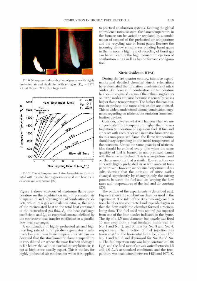
Figure 6 exhibits the distribution of reaction zonein non-premixed combustion of propane injectedinto a highly preheated airstream and a nitrogen-diluted airstream. Widely distributed reactions oflow oxygen combustion are very different comparedwith the more concentrated reaction in an ordinaryoxygen atmosphere. It is suggested that the heat re-lease due to combustion reaction is also distributedyielding a dispersed and moderate temperature rise.
One of us (Hasegawa) has discussed the individualand multiple influence of heat and gas recycling [22].
COMBUSTION IN HIGHLY PREHEATED AIR 3139
Fig 6. Non-premixed combustion of propane with highlypreheated air and air diluted with nitrogen. (Tair 4 1273K). (a) Oxygen 21%; (b) Oxygen 4%.
Fig 7. Flame temperature of stoichiometric mixture di-luted with recycled burnt gases associated with heat recir-culation and abstraction [22].
Figure 7 shows contours of maximum flame tem-perature on the combination map of preheated airtemperature and recycling rate of combustion prod-ucts, where R is gas recirculation ratio, a, the ratioof the recirculated heat to the total heat containedin the recirculated gas flow, nh, the heat exchangecoefficient, and nm, an empirical constant defined bythe convective heat transfer coefficient in a parallelflow heat exchanger.
A combination of highly preheated air and highrecycling rate of burnt products generates a rela-tively low maximum flame temperatures. We can un-derstand that the stoichiometric flame temperaturein very diluted air, where the mass fraction of oxygenis far below the value in normal atmospheric air, isnot as high as we usually expect. This is the key forhighly preheated air combustion when it is applied
to practical combustion systems. Keeping the globalequivalence ratio constant, the flame temperature inthe furnace can be varied or regulated by a combi-nation of control of the preheated air temperatureand the recycling rate of burnt gases. Because theincoming airflow entrains surrounding burnt gasesin the furnace, a high rate of recycling of burnt gascan be induced by the high momentum ejection ofcombustion air as well as by the furnace configura-tion.
Nitric Oxides in HPAC
During the last quarter century, intensive experi-ments and detailed chemical kinetic calculationshave elucidated the formation mechanisms of nitricoxides. An increase in combustion air temperaturehas been recognized as one of the influencing factorson nitric oxides emission because it generally causeshigher flame temperatures. The higher the combus-tion air preheat, the more nitric oxides are emitted.This is widely understood among combustion engi-neers regarding on nitric oxides emission from com-bustion devices.
Consider, however, what will happen when we useair preheated to a temperature higher than the au-toignition temperature of a gaseous fuel. If fuel andair react with each other at a near-stoichiometric ra-tio in a non-premixed flame, the flame temperatureshould vary depending on the initial temperature ofthe reactants. Almost the same quantity of nitric ox-ides should be emitted every time when the samequantity of fuel is burned in non-premixed flameswith the same air preheat. This is a conjecture basedon the assumption that a similar flow structure oc-curs with highly preheated air as with ambient tem-perature air. However, we obtained experimental re-sults showing that the emission of nitric oxideschanged significantly by changing only the mixingprocess between the fuel and air, keeping the flowrates and temperatures of the fuel and air constant[26].
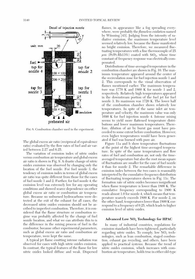
The outline of the experiments is described next.Figure 8 shows the combustion chamber used in theexperiment. The inlet of the 300-mm-long combus-tion chamber was contracted and expanded again sothat the flow inside the chamber formed a recircu-lating flow. The fuel used was natural gas injectedfrom one of the four nozzles indicated in the figure.The tip of a 1.5-mm-diameter fuel nozzle was fixed10 mm away from a heat insulated inside wall forNo. 1 and No. 2, and 30 mm for No. 3 and No. 4,respectively. The direction of fuel injection wastaken at 708 to the horizontal fuel tube, upward forNo. 1 and No. 3 and downward for No. 2 and No.4. The fuel injection rate was kept constant at 0.06LN/s, and the feed rate of air was varied between 1.5and 4.0 LN/s at standard conditions, and the tem-perature was maintained between 1423 and 1073 K.
3140 INVITED TOPICAL REVIEW
Fig 8. Combustion chamber used in the experiment.
The global excess air ratio (reciprocal of equivalenceratio) evaluated by the flow rates of fuel and air var-ied between 2.27 and 6.25.
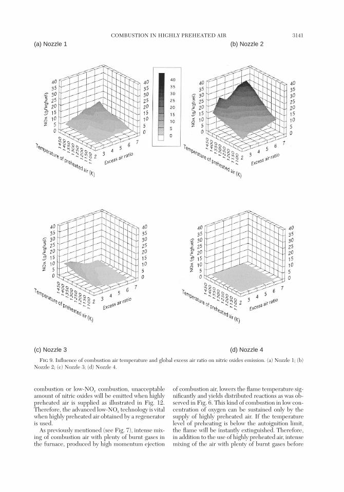
The variation of emission index of nitric oxidesversus combustion air temperature and global excessair ratio is shown in Fig. 9. A drastic change of nitricoxides emission was observed by changing only thelocation of the fuel nozzle. For fuel nozzle 3, thetendency of emission index in terms of global excessair ratio was quite different from those for the casesof fuel nozzle 1 and 2. Further, for fuel nozzle 4, theemission level was extremely low for any operatingconditions and showed scarce dependence on eitherglobal excess air ratio or combustion air tempera-ture. Because no unburned hydrocarbons were de-tected at the exit of the exhaust for all cases, thedecreased nitric oxides emission should not be as-cribed to imperfect combustion. Therefore, it is con-sidered that the flame structure or combustion re-gime was probably affected by the change of fuelnozzle location, and what we can attribute this to isthe difference in the mixing process of fuel in thecombustor, because other experimental parameters,such as global excess air ratio and combustion airtemperature, were kept the same.
A typical jet flame emitting intense radiation wasobserved for cases with high nitric oxides emission.In contrast, the typical features of the flame for lownitric oxides looked diffuse and weak. Dispersed
flames, in appearance like a fog spreading every-where, were probably the flameless oxidation namedby Wunning [43]. Judging from the intensity of ra-diative emission, the maximum temperature levelseemed relatively low, because the flame manifestedno bright emission. Therefore, we measured fluc-tuating temperatures with a fine thermocouple of 25lm (Pt/Pt-Rh13%) coated with SiO2, whose timeconstant of frequency response was electrically com-pensated.
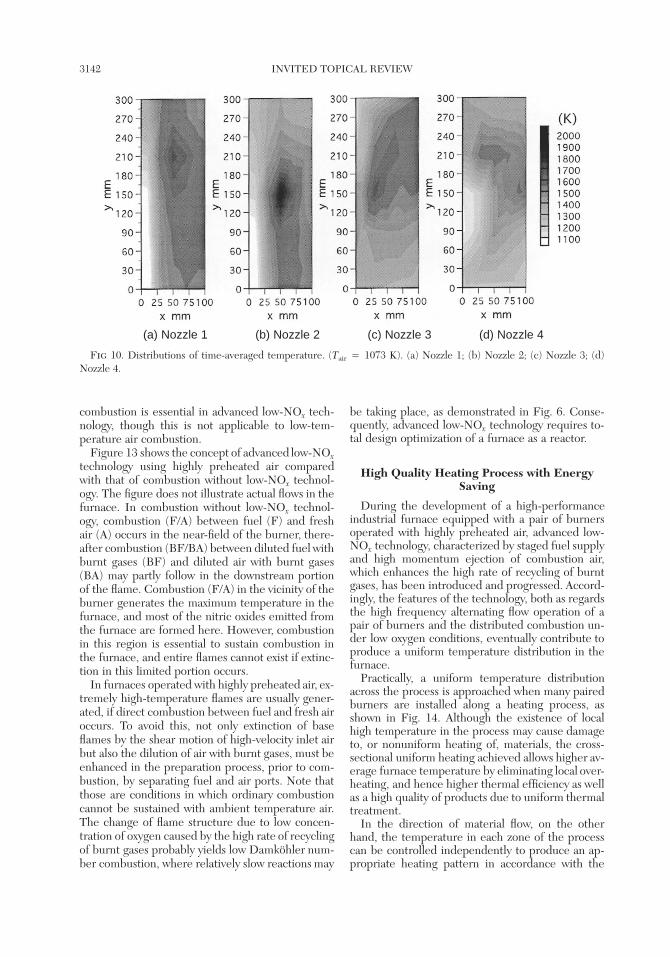
Distributions of time-averaged temperature in thecombustion chamber are shown in Fig. 10. The max-imum temperature appeared around the center ofthe recirculation zone for fuel injection nozzle 1 and2. This corresponds to the visual observation offlames mentioned earlier. The maximum tempera-ture was 1770 K and 1860 K for nozzle 1 and 2,respectively. Relatively high temperatures appearedin the downstream portion of the fuel jet for fuelnozzle 3. Its maximum was 1720 K. The lower halfof the combustion chamber shows relatively lowtemperatures. In spite of the same inlet air tem-perature and velocity, the maximum value was only1690 K for fuel injection nozzle 4. Intense mixingseems to yield more flattened temperature distri-butions and lower maximum temperatures. There-fore, dilution of air by burnt gas must have pro-ceeded to some extent before combustion. However,even higher temperatures would have been gener-ated if fuel was burned with pure air.
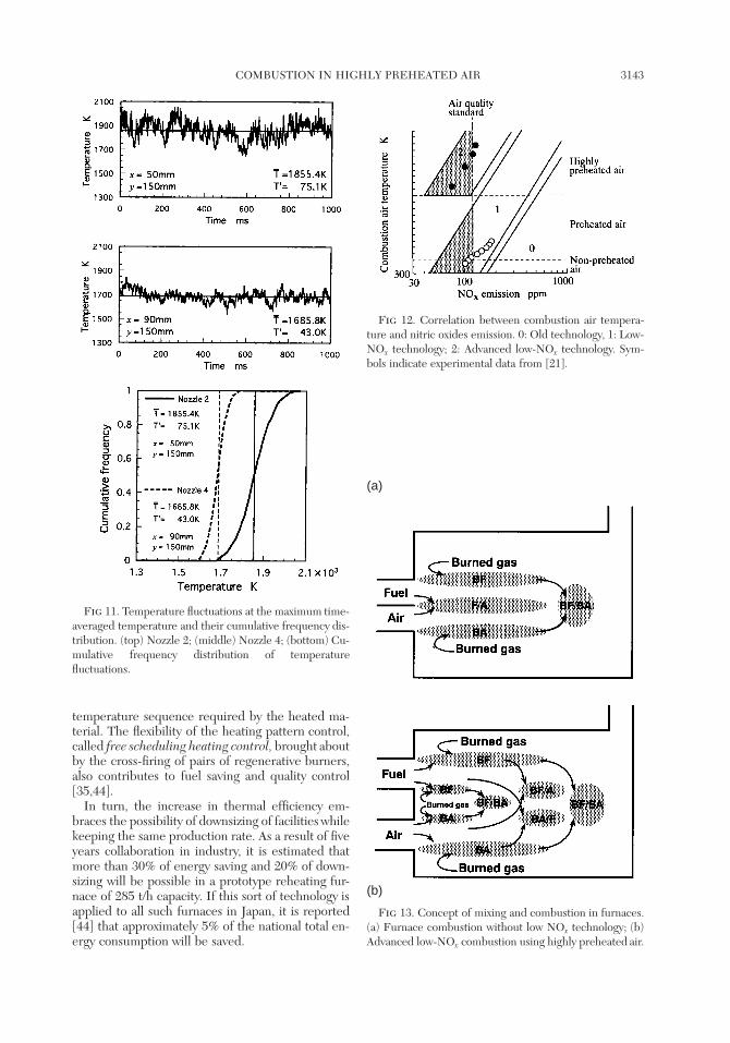
Figure 11a and b show temperature fluctuationsat the point of the highest time-averaged tempera-ture. In spite of the same temperatures and flowrates of fuel and combustion air, not only the time-averaged temperature but also the root mean squareof fluctuations are smaller for the case of fuel nozzle4 than for nozzle 2. The remarkable difference inemission index between the two cases is reasonablyinterpreted by the cumulative frequency distributionof fluctuating temperatures shown in Fig. 11c. Theformation rate of nitric oxides becomes insignificantwhen flame temperature is lower than 1800 K. Thecumulative frequency corresponding to 1800 Kreads almost 1.0 for nozzle 4, which means that tem-perature scarcely exceeds 1800 K. For nozzle 2, onthe other hand, temperatures lower than 1800 K cor-respond to a frequency of 0.25, which leads to higheremission level of nitric oxides.
Advanced Low NOx Technology for HPAC
In many of industrial countries, regulations foremission standards have been tightened, particularlyregarding nitric oxides. To comply, low NOx tech-nologies, such as lean combustion, staged combus-tion, exhaust gas recycling, and others, have beenapplied to practical systems. Because the trend ofnitric oxides emission, which increases with com-bustion air temperature, holds true in either old-type
COMBUSTION IN HIGHLY PREHEATED AIR 3141
(a) Nozzle 1 (b) Nozzle 2
(c) Nozzle 3 (d) Nozzle 4
Fig 9. Influence of combustion air temperature and global excess air ratio on nitric oxides emission. (a) Nozzle 1; (b)Nozzle 2; (c) Nozzle 3; (d) Nozzle 4.
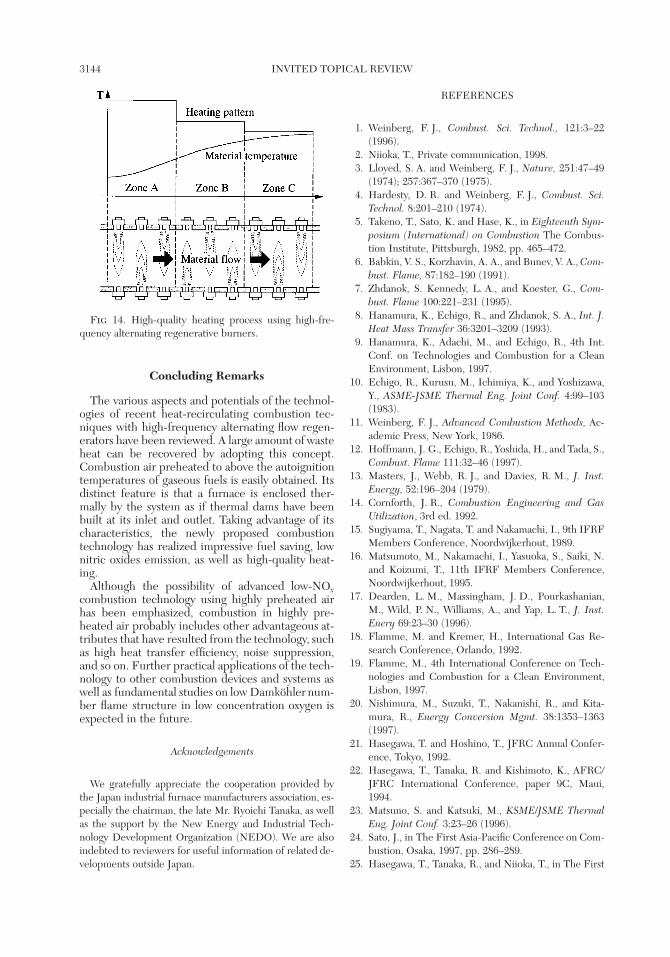
combustion or low-NOx combustion, unacceptableamount of nitric oxides will be emitted when highlypreheated air is supplied as illustrated in Fig. 12.Therefore, the advanced low-NOx technology is vitalwhen highly preheated air obtained by a regeneratoris used.
As previously mentioned (see Fig. 7), intense mix-ing of combustion air with plenty of burnt gases inthe furnace, produced by high momentum ejection
of combustion air, lowers the flame temperature sig-nificantly and yields distributed reactions as was ob-served in Fig. 6. This kind of combustion in low con-centration of oxygen can be sustained only by thesupply of highly preheated air. If the temperaturelevel of preheating is below the autoignition limit,the flame will be instantly extinguished. Therefore,in addition to the use of highly preheated air, intensemixing of the air with plenty of burnt gases before
3142 INVITED TOPICAL REVIEW
(a) Nozzle 1 (b) Nozzle 2 (c) Nozzle 3 (d) Nozzle 4
Fig 10. Distributions of time-averaged temperature. (Tair 4 1073 K). (a) Nozzle 1; (b) Nozzle 2; (c) Nozzle 3; (d)Nozzle 4.
combustion is essential in advanced low-NOx tech-nology, though this is not applicable to low-tem-perature air combustion.
Figure 13 shows the concept of advanced low-NOx
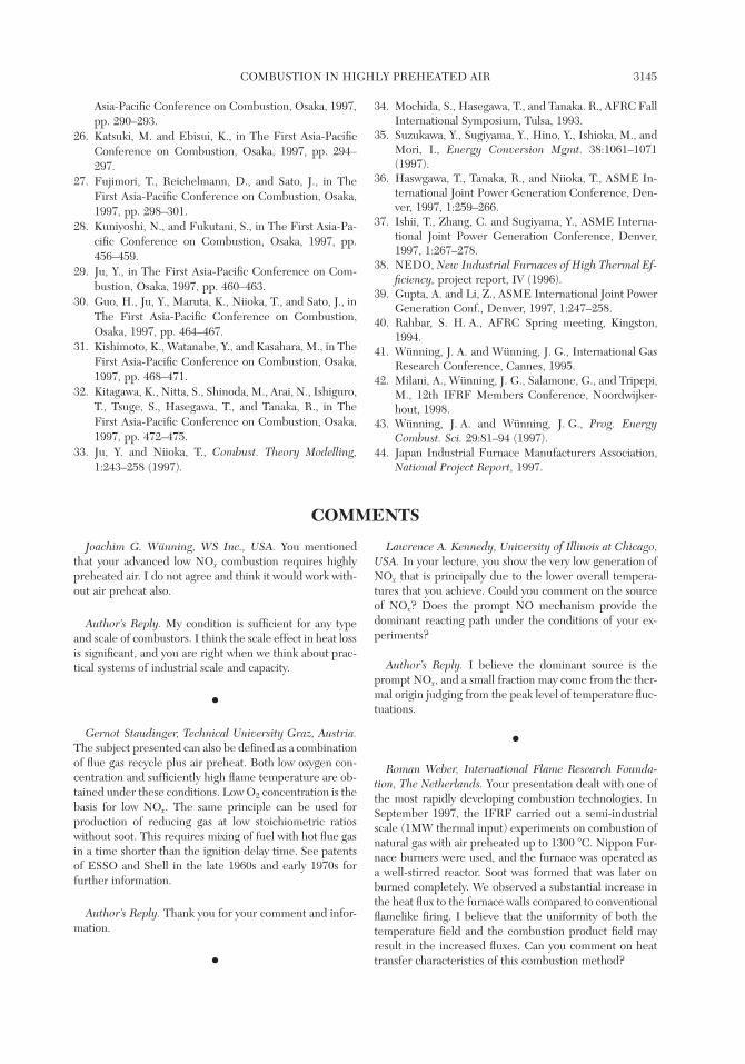
technology using highly preheated air comparedwith that of combustion without low-NOx technol-ogy. The figure does not illustrate actual flows in thefurnace. In combustion without low-NOx technol-ogy, combustion (F/A) between fuel (F) and freshair (A) occurs in the near-field of the burner, there-after combustion (BF/BA) between diluted fuel withburnt gases (BF) and diluted air with burnt gases(BA) may partly follow in the downstream portionof the flame. Combustion (F/A) in the vicinity of theburner generates the maximum temperature in thefurnace, and most of the nitric oxides emitted fromthe furnace are formed here. However, combustionin this region is essential to sustain combustion inthe furnace, and entire flames cannot exist if extinc-tion in this limited portion occurs.
In furnaces operated with highly preheated air, ex-tremely high-temperature flames are usually gener-ated, if direct combustion between fuel and fresh airoccurs. To avoid this, not only extinction of baseflames by the shear motion of high-velocity inlet airbut also the dilution of air with burnt gases, must beenhanced in the preparation process, prior to com-bustion, by separating fuel and air ports. Note thatthose are conditions in which ordinary combustioncannot be sustained with ambient temperature air.The change of flame structure due to low concen-tration of oxygen caused by the high rate of recyclingof burnt gases probably yields low Damkohler num-ber combustion, where relatively slow reactions may
be taking place, as demonstrated in Fig. 6. Conse-quently, advanced low-NOx technology requires to-tal design optimization of a furnace as a reactor.
High Quality Heating Process with EnergySaving
During the development of a high-performanceindustrial furnace equipped with a pair of burnersoperated with highly preheated air, advanced low-NOx technology, characterized by staged fuel supplyand high momentum ejection of combustion air,which enhances the high rate of recycling of burntgases, has been introduced and progressed. Accord-ingly, the features of the technology, both as regardsthe high frequency alternating flow operation of apair of burners and the distributed combustion un-der low oxygen conditions, eventually contribute toproduce a uniform temperature distribution in thefurnace.
Practically, a uniform temperature distributionacross the process is approached when many pairedburners are installed along a heating process, asshown in Fig. 14. Although the existence of localhigh temperature in the process may cause damageto, or nonuniform heating of, materials, the cross-sectional uniform heating achieved allows higher av-erage furnace temperature by eliminating local over-heating, and hence higher thermal efficiency as wellas a high quality of products due to uniform thermaltreatment.
In the direction of material flow, on the otherhand, the temperature in each zone of the processcan be controlled independently to produce an ap-propriate heating pattern in accordance with the
COMBUSTION IN HIGHLY PREHEATED AIR 3143
Fig 11. Temperature fluctuations at the maximum time-averaged temperature and their cumulative frequency dis-tribution. (top) Nozzle 2; (middle) Nozzle 4; (bottom) Cu-mulative frequency distribution of temperaturefluctuations.
Fig 12. Correlation between combustion air tempera-ture and nitric oxides emission. 0: Old technology, 1: Low-NOx technology; 2: Advanced low-NOx technology. Sym-bols indicate experimental data from [21].
(a)
(b)
Fig 13. Concept of mixing and combustion in furnaces.(a) Furnace combustion without low NOx technology; (b)Advanced low-NOx combustion using highly preheated air.
temperature sequence required by the heated ma-terial. The flexibility of the heating pattern control,called free scheduling heating control, brought aboutby the cross-firing of pairs of regenerative burners,also contributes to fuel saving and quality control[35,44].
In turn, the increase in thermal efficiency em-braces the possibility of downsizing of facilities whilekeeping the same production rate. As a result of fiveyears collaboration in industry, it is estimated thatmore than 30% of energy saving and 20% of down-sizing will be possible in a prototype reheating fur-nace of 285 t/h capacity. If this sort of technology isapplied to all such furnaces in Japan, it is reported[44] that approximately 5% of the national total en-ergy consumption will be saved.
3144 INVITED TOPICAL REVIEW
Fig 14. High-quality heating process using high-fre-quency alternating regenerative burners.
Concluding Remarks
The various aspects and potentials of the technol-ogies of recent heat-recirculating combustion tec-niques with high-frequency alternating flow regen-erators have been reviewed. A large amount of wasteheat can be recovered by adopting this concept.Combustion air preheated to above the autoignitiontemperatures of gaseous fuels is easily obtained. Itsdistinct feature is that a furnace is enclosed ther-mally by the system as if thermal dams have beenbuilt at its inlet and outlet. Taking advantage of itscharacteristics, the newly proposed combustiontechnology has realized impressive fuel saving, lownitric oxides emission, as well as high-quality heat-ing.
Although the possibility of advanced low-NOx
combustion technology using highly preheated airhas been emphasized, combustion in highly pre-heated air probably includes other advantageous at-tributes that have resulted from the technology, suchas high heat transfer efficiency, noise suppression,and so on. Further practical applications of the tech-nology to other combustion devices and systems aswell as fundamental studies on low Damkohler num-ber flame structure in low concentration oxygen isexpected in the future.
Acknowledgements
We gratefully appreciate the cooperation provided bythe Japan industrial furnace manufacturers association, es-pecially the chairman, the late Mr. Ryoichi Tanaka, as wellas the support by the New Energy and Industrial Tech-nology Development Organization (NEDO). We are alsoindebted to reviewers for useful information of related de-velopments outside Japan.
REFERENCES
1. Weinberg, F. J., Combust. Sci. Technol., 121:3–22(1996).
2. Niioka, T., Private communication, 1998.3. Lloyed, S. A. and Weinberg, F. J., Nature, 251:47–49
(1974); 257:367–370 (1975).4. Hardesty, D. R. and Weinberg, F. J., Combust. Sci.
Technol. 8:201–210 (1974).5. Takeno, T., Sato, K. and Hase, K., in Eighteenth Sym-
posium (International) on Combustion The Combus-tion Institute, Pittsburgh, 1982, pp. 465–472.
6. Babkin, V. S., Korzhavin, A. A., and Bunev, V. A., Com-
bust. Flame, 87:182–190 (1991).7. Zhdanok, S. Kennedy, L. A., and Koester, G., Com-
bust. Flame 100:221–231 (1995).8. Hanamura, K., Echigo, R., and Zhdanok, S. A., Int. J.
Heat Mass Transfer 36:3201–3209 (1993).9. Hanamura, K., Adachi, M., and Echigo, R., 4th Int.
Conf. on Technologies and Combustion for a CleanEnvironment, Lisbon, 1997.
10. Echigo, R., Kurusu, M., Ichimiya, K., and Yoshizawa,Y., ASME-JSME Thermal Eng. Joint Conf. 4:99–103(1983).
11. Weinberg, F. J., Advanced Combustion Methods, Ac-ademic Press, New York, 1986.
12. Hoffmann, J. G., Echigo, R., Yoshida, H., and Tada, S.,Combust. Flame 111:32–46 (1997).
13. Masters, J., Webb, R. J., and Davies, R. M., J. Inst.
Energy, 52:196–204 (1979).14. Cornforth, J. R., Combustion Engineering and Gas
Utilization, 3rd ed. 1992.15. Sugiyama, T., Nagata, T. and Nakamachi, I., 9th IFRF
Members Conference, Noordwijkerhout, 1989.16. Matsumoto, M., Nakamachi, I., Yasuoka, S., Saiki, N.
and Koizumi, T., 11th IFRF Members Conference,Noordwijkerhout, 1995.
17. Dearden, L. M., Massingham, J. D., Pourkashanian,M., Wild, P. N., Williams, A., and Yap, L. T., J. Inst.
Enery 69:23–30 (1996).18. Flamme, M. and Kremer, H., International Gas Re-
search Conference, Orlando, 1992.19. Flamme, M., 4th International Conference on Tech-
nologies and Combustion for a Clean Environment,Lisbon, 1997.
20. Nishimura, M., Suzuki, T., Nakanishi, R., and Kita-mura, R., Energy Conversion Mgmt. 38:1353–1363(1997).
21. Hasegawa, T. and Hoshino, T., JFRC Annual Confer-ence, Tokyo, 1992.
22. Hasegawa, T., Tanaka, R. and Kishimoto, K., AFRC/JFRC International Conference, paper 9C, Maui,1994.
23. Matsuno, S. and Katsuki, M., KSME/JSME Thermal
Eng. Joint Conf. 3:23–26 (1996).24. Sato, J., in The First Asia-Pacific Conference on Com-
bustion, Osaka, 1997, pp. 286–289.25. Hasegawa, T., Tanaka, R., and Niioka, T., in The First
COMBUSTION IN HIGHLY PREHEATED AIR 3145
Asia-Pacific Conference on Combustion, Osaka, 1997,pp. 290–293.
26. Katsuki, M. and Ebisui, K., in The First Asia-PacificConference on Combustion, Osaka, 1997, pp. 294–297.
27. Fujimori, T., Reichelmann, D., and Sato, J., in TheFirst Asia-Pacific Conference on Combustion, Osaka,1997, pp. 298–301.
28. Kuniyoshi, N., and Fukutani, S., in The First Asia-Pa-cific Conference on Combustion, Osaka, 1997, pp.456–459.
29. Ju, Y., in The First Asia-Pacific Conference on Com-bustion, Osaka, 1997, pp. 460–463.
30. Guo, H., Ju, Y., Maruta, K., Niioka, T., and Sato, J., inThe First Asia-Pacific Conference on Combustion,Osaka, 1997, pp. 464–467.
31. Kishimoto, K., Watanabe, Y., and Kasahara, M., in TheFirst Asia-Pacific Conference on Combustion, Osaka,1997, pp. 468–471.
32. Kitagawa, K., Nitta, S., Shinoda, M., Arai, N., Ishiguro,T., Tsuge, S., Hasegawa, T., and Tanaka, R., in TheFirst Asia-Pacific Conference on Combustion, Osaka,1997, pp. 472–475.
33. Ju, Y. and Niioka, T., Combust. Theory Modelling,
1:243–258 (1997).
34. Mochida, S., Hasegawa, T., and Tanaka. R., AFRC FallInternational Symposium, Tulsa, 1993.
35. Suzukawa, Y., Sugiyama, Y., Hino, Y., Ishioka, M., andMori, I., Energy Conversion Mgmt. 38:1061–1071(1997).
36. Haswgawa, T., Tanaka, R., and Niioka, T., ASME In-ternational Joint Power Generation Conference, Den-ver, 1997, 1:259–266.
37. Ishii, T., Zhang, C. and Sugiyama, Y., ASME Interna-tional Joint Power Generation Conference, Denver,1997, 1:267–278.
38. NEDO, New Industrial Furnaces of High Thermal Ef-
ficiency, project report, IV (1996).39. Gupta, A. and Li, Z., ASME International Joint Power
Generation Conf., Denver, 1997, 1:247–258.40. Rahbar, S. H. A., AFRC Spring meeting, Kingston,
1994.41. Wunning, J. A. and Wunning, J. G., International Gas
Research Conference, Cannes, 1995.42. Milani, A., Wunning, J. G., Salamone, G., and Tripepi,
M., 12th IFRF Members Conference, Noordwijker-hout, 1998.
43. Wunning, J. A. and Wunning, J. G., Prog. Energy
Combust. Sci. 29:81–94 (1997).44. Japan Industrial Furnace Manufacturers Association,
National Project Report, 1997.
COMMENTS
Joachim G. Wunning, WS Inc., USA. You mentionedthat your advanced low NOx combustion requires highlypreheated air. I do not agree and think it would work with-out air preheat also.
Author’s Reply. My condition is sufficient for any typeand scale of combustors. I think the scale effect in heat lossis significant, and you are right when we think about prac-tical systems of industrial scale and capacity.
●
Gernot Staudinger, Technical University Graz, Austria.
The subject presented can also be defined as a combinationof flue gas recycle plus air preheat. Both low oxygen con-centration and sufficiently high flame temperature are ob-tained under these conditions. Low O2 concentration is thebasis for low NOx. The same principle can be used forproduction of reducing gas at low stoichiometric ratioswithout soot. This requires mixing of fuel with hot flue gasin a time shorter than the ignition delay time. See patentsof ESSO and Shell in the late 1960s and early 1970s forfurther information.
Author’s Reply. Thank you for your comment and infor-mation.
●
Lawrence A. Kennedy, University of Illinois at Chicago,
USA. In your lecture, you show the very low generation ofNOx that is principally due to the lower overall tempera-tures that you achieve. Could you comment on the sourceof NOx? Does the prompt NO mechanism provide thedominant reacting path under the conditions of your ex-periments?
Author’s Reply. I believe the dominant source is theprompt NOx, and a small fraction may come from the ther-mal origin judging from the peak level of temperature fluc-tuations.
●
Roman Weber, International Flame Research Founda-
tion, The Netherlands. Your presentation dealt with one ofthe most rapidly developing combustion technologies. InSeptember 1997, the IFRF carried out a semi-industrialscale (1MW thermal input) experiments on combustion ofnatural gas with air preheated up to 1300 8C. Nippon Fur-nace burners were used, and the furnace was operated asa well-stirred reactor. Soot was formed that was later onburned completely. We observed a substantial increase inthe heat flux to the furnace walls compared to conventionalflamelike firing. I believe that the uniformity of both thetemperature field and the combustion product field mayresult in the increased fluxes. Can you comment on heattransfer characteristics of this combustion method?

3146 INVITED TOPICAL REVIEW
Author’s Reply. We completely agree with you. The uni-form temperature field, even though it is not high enough,probably results in higher heat transfer rate to cold mate-rials, the only destination of effective heat than that of con-ventional flamelike firing. This is because, however highthe peak temperature is in the latter case, the volume ofhigh temperature is localized and radiative heat transferfrom the volume diverges in all directions, not to cold ma-terials only. We also observed some soot was formed in theearlier stage of reaction of the injected fuel, and it disap-peared rapidly with the progress of mixing.
●
Antonio Cavaliere, University of Naples, Italy. It is ofinterest to note that the technology of highly preheated airis able to reduce the NOx production with the use of par-ticular additional contrivances like staging or a high levelof flue gas recirculation. Do you know any practical devicein which the technology you have described is used underhigh-pressure conditions?
Author’s Reply. There is not any practical device workingunder high pressure, in which the technology in the paperis used, as far as I know. However, the basic study of theapplication to new fields, such as a gas turbine engine, isbeing explored.


![KYOTO-OSAKA KYOTO KYOTO-OSAKA SIGHTSEEING PASS … · KYOTO-OSAKA SIGHTSEEING PASS < 1day > KYOTO-OSAKA SIGHTSEEING PASS [for Hirakata Park] KYOTO SIGHTSEEING PASS KYOTO-OSAKA](https://img.pdfslide.net/doc/110x75/5ed0f3d62a742537f26ea1f1/kyoto-osaka-kyoto-kyoto-osaka-sightseeing-pass-kyoto-osaka-sightseeing-pass-.jpg)