Embed Size (px)
Citation preview

275038
JPRS-JST-87-024 29 JULY 1987
■■■■■l ■■■■■f wmwrs
FOREIGN BROADCAST INFORMATION SERVICE
JPRS $1$
Science & Technology
DIBTM»OnON 8YATEMZHT Ä
Approved fear jw&iie twiwacBSf
Japan
19980610 166
REPRODUCED BY U.S. DEPARTMENTOF COMMERCE
NATIONAL TECHNICAL INFORMATIONSERVICE SPRINGFIELD, VA 22161
pnc QUALITY INSPECTED Q
10
*z
JPRS-JST-87-024
29 JULY 1987
SCIENCE & TECHNOLOGY
JAPAN
CONTENTS
ADVANCED MATERIALS
Development of Materials for Automobiles Reported (NIKKO MATERIALS, Oct 86) 1
Status of Materials for Magnetooptical Elements Discussed (Naoki Koshizuka, et al.; KINO ZAIRYO, Feb 87) 12
Basic Research for Promotion of Ceramics Discussed (Osami Kamigaito; CERAMICS JAPAN, Dec 86) 27
Development of Organic Photomemories Discussed (Kazuyuki Horie; KINO ZAIRYO, Sep 86) 35
AEROSPACE, CIVIL AVIATION
New Materials Applications to Aircraft Engines Discussed (KOKU GIJUTSU, Jan 87) 50
National Aerospace Laboratory News—December 1986 (KOGIKEN NYUSU, Dec 86) > 56
ATP Propeller Analysis, by Shigeru Saito 56 Null-Collision Technique, by Katsuhisa Koura 59 Laminated Carbon Fiber Composite, by Ryuji Ishikawa 60 Flutter Control Experiment 64 Three-Dimensional Duct Flow 66
Payload Tether Technology, by Shoichi Yoshimura 68
- a -

BIOTECHNOLOGY
Problems in Application of Biotechnology to Wastewater Treatment (BIOINDUSTRY, Dec 86) 71
/9986
~ b -

ADVANCED MATERIALS
DEVELOPMENT OF MATERIALS FOR AUTOMOBILES REPORTED
Tokyo NIKKO MATERIALS in Japanese Oct 86 pp 1-12
[Excerpts] 1. Introduction
The total number of automobiles produced during 1985 in Japan was 12.27 million. This was an increase of 10 percent over the previous year and is the highest record in history. As a result, Japan continuously holds the foremost place in the production of automobiles for the past 6 years (Figure 1).
x million units
Figure 1.
United States
72 73 74 75
Transition of Total Number of Automobiles Produced by Main Countries
On this background, it can be pointed out that the sphere of quantitative import controls by the United States was widened by about 10 percent, and also the total number of automobiles for the domestic market reached

5.55 million, an increase of 2 percent over the previous year because each car maker introduced new models into the market.
However, due to the worsening of trade friction between the United States and Japan these days, and a change in world economics such as the tendency of a strong yen and weak dollar, Japanese automobile makers are going to start on- site production in Europe and the United States. In addition, due to the introduction of low-priced compact cars by the three major U.S. automobile manufacturers, and an increase in the sales of Korean and Yugoslav-made low- priced cars on the U.S. market, a drastic increase in the sale of Japanese cars cannot now be expected. An era in which Japanese automobile makers need to make efforts to expand demand in the domestic market seems to be steadily approaching. Furthermore, from the fact that the life of most auto- mobiles is about 10 years, it is considered that sales competition will worsen.
Under these circumstances, higher performance, higher functions, and indivi- duality are expected to be in demand for automobiles in the future. In order to meet such demands, "materials" could play an important role.
In this paper, among various materials for automobiles, the present state and developmental trend of metallic materials, nonmetallic materials, and ceramics are to be discussed.
2. Materials for Automobiles and Their Subjects
An example of the estimation of composition materials for automobiles in the future is shown in Figure 2 [omitted]. Generally speakings the following tendency can be seen.
(1) The rate of steel materials has decreased from 80 to 76 percent, and more reduction will be seen in 1986. However, since a lightweight car body and the improvement of rust protection are very important subjects, there is a tendency to increase the amount of high-strength and rustproof steel plates in use.
(2) There is no drastic change regarding nonferrous metals, and the amount is about 5.5 percent. When light weight is considered for this material, it is estimated that there is an increase in the amount of aluminum used.
(3) In the case of nonmetallic materials, the amount of plastics used is increasing. It is considered that this tendency will last in the future. On the contrary, there is a slight decrease in the amount of paint and rubber. The application of ceramics for not only catalytic carriers, but also func- tional parts such as sensors, and structural components represented by thermal exchangers and engine parts is expanding. Therefore, the amount of ceramics used is estimated to increase.
Under the present circumstances, in making an advance in the development of an automobile hereafter, economical efficiency (an improvement in fuel con- sumption), riding comfort, durability, and an improvement in safety could be taken up as themes. Figure 3 [omitted] shows a summary of these. As seen
from this figure, these themes are very closely related to materials. Without the development of materials, many themes could not be achieved.
3. Present State and Development Trend of Materials for Automobiles
3.1 Metallic Materials
Metallic materials are central to the materials used for an automobile. Due to the themes described above, the development of new materials is enthusias- tically carried out. They are, for instance,material to give high strength and light weight in order to improve fuel consumption, rustproof steel plates for the improvement of corrosion resistance, laminated steel plates for light weight and antivibration (damping), and high functional materials such as aluminum alloy, FRM (fiber-reinforced metal), and SMA (shape-memory alloy). Some of them have already been put into practical use.
(1) High-Strength Steel
In traditional ways of thinking, high-strength steel sheets have been used for bumper reinforcement, door impact beams, and so on. However, due to the requirement of a lightweight body, there is a positive tendency to apply this material to inner or outer panels of a body.
High-strength steel has the advantage of maintaining designated strength with a reduction in weight. But if this material is hard and has high strength, the occurrence of cracks and wrinkles may appear under the molding process. Depending on added elements, there could be degradation in welding, deteriora- tion in the life of a mold, and an increase in cost. High-strength steel has not only advantages» but also these negative characteristics.
Therefore, BH (bake hardening) type high-strength steel sheets, high-strength steel sheets for high deep drawing, phosphorous-added aluminum-killed, high- strength steel sheets, and composite structure type high-strength steel sheets (dual phase steel) are presently under development. Besides application for the car body, these materials are also utilized for disk wheels and suspension components.
(2) Rustproof Steel Sheets
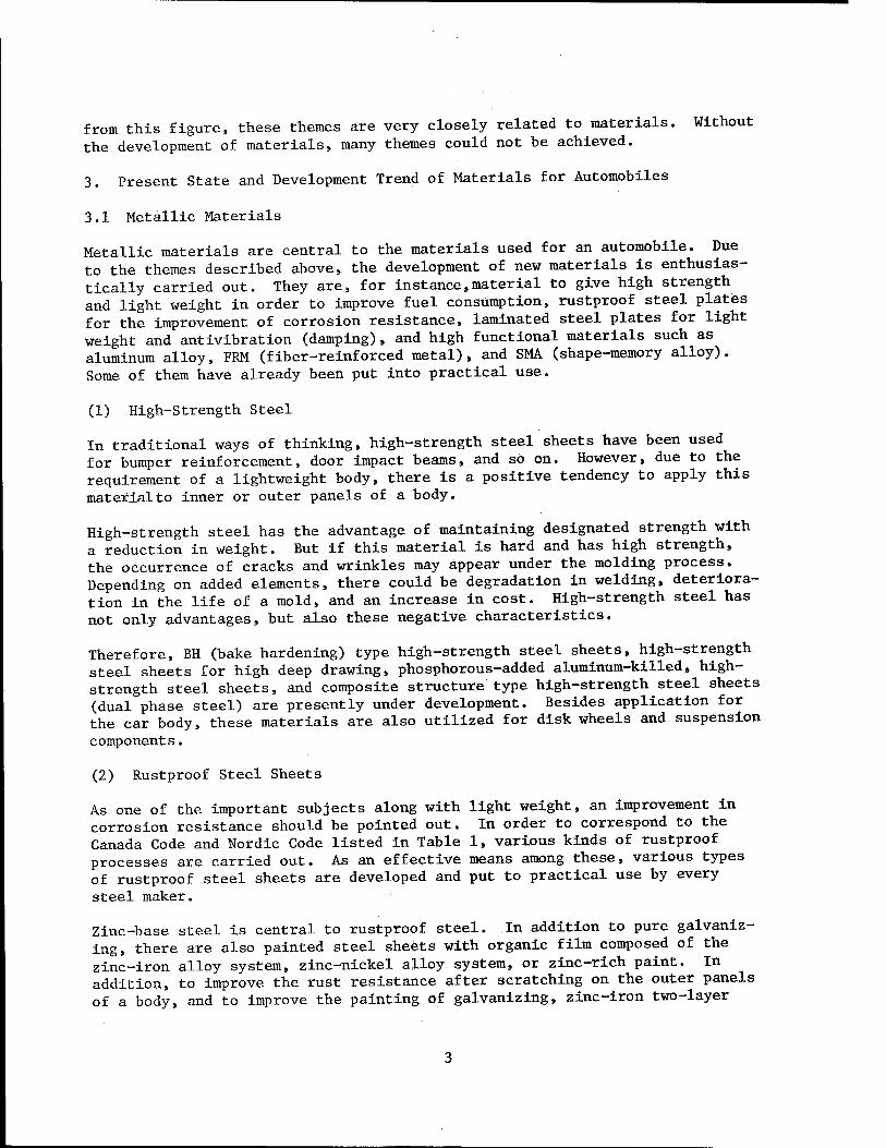
As one of the important subjects along with light weight, an improvement in corrosion resistance should be pointed out. In order to correspond to the Canada Code and Nordic Code listed in Table 1, various kinds of rustproof processes are carried out. As an effective means among these, various types of rustproof steel sheets are developed and put to practical use by every steel maker.
Zinc-base steel is central to rustproof steel. In addition to pure galvaniz- ing, there are also painted steel sheets with organic film composed of the zinc-iron alloy system, zinc-nickel alloy system, or zinc-rich paint. In addition, to improve the rust resistance after scratching on the outer panels of a body, and to improve the painting of galvanizing, zinc-iron two-layer
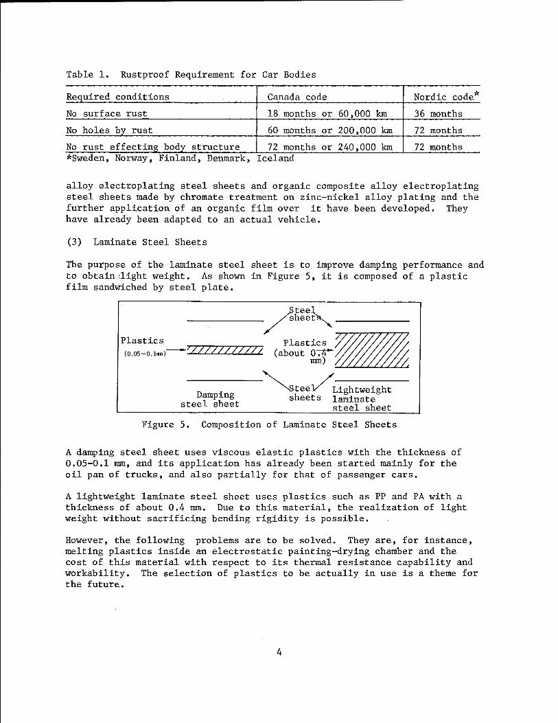
Table 1. Rustproof Requirement for Car Bodies
Required conditions Canada code Nordic code
No surface rust 18 months or 60,000 km 36 months
No holes by rust 60 months or 200,000 km 72 months
No rust effecting body- structure 72 months or 240,000 km 72 months *Sweden, Norway, Finland, Denmark, Iceland
alloy electroplating steel sheets and organic composite alloy electroplating steel sheets made by chromate treatment on zinc-nickel alloy plating and the further application of an organic film over it have been developed. They have already been adapted to an actual vehicle.
(3) Laminate Steel Sheets
The purpose of the laminate steel sheet is to improve damping performance and to obtain-.dight weight. As shown in Figure 5, it is composed of a plastic film sandwiched by steel plate.
>teel sheets^
Plastics Plastics (o.o5~o.lmm) *"''/////////// (about 074*
mm)
Damping steel sheet
tee]/ Lightweight sheets laminate
steel sheet
Figure 5. Composition of Laminate Steel Sheets
A damping steel sheet uses viscous elastic plastics with the thickness of 0.05-0.1 mm, and its application has already been started mainly for the oil pan of trucks, and also partially for that of passenger cars.
A lightweight laminate steel sheet uses plastics such as PP and PA with a thickness of about 0.4 mm. Due to this material, the realization of light weight without sacrificing bending rigidity is possible.
However, the following problems are to be solved. They are, for instance, melting plastics inside an electrostatic painting-drying chamber and the cost of this material with respect to its thermal resistance capability and workability. The selection of plastics to be actually in use is a theme for the future.
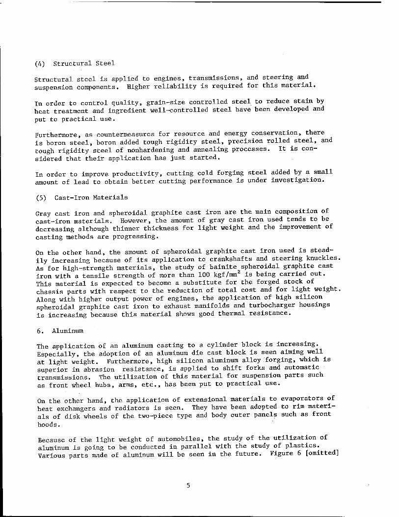
(4) Structural Steel
Structural steel is applied to engines, transmissions, and steering and suspension components. Higher reliability is required for this material.
In order to control quality, grain-size controlled steel to reduce stain by heat treatment and ingredient well-controlled steel have been developed and
put to practical use.
Furthermore, as countermeasures for resource and energy conservation, there is boron steel, boron added tough rigidity steel, precision rolled steel, and tough rigidity steel of nonhardening and annealing processes. It is con- sidered that their application has just started.
In order to improve productivity, cutting cold forging steel added by a small amount of lead to obtain better cutting performance is under investigation.
(5) Cast-iron Materials
Gray cast iron and spheroidal graphite cast iron are the main composition of cast-iron materials. However, the amount of gray cast iron used tends to be decreasing although thinner thickness for light weight and the improvement of
casting methods are progressing.
On the other hand, the amount of spheroidal graphite cast iron used is stead- ily increasing because of its application to crankshafts and steering knuckles. As for high-strength materials, the study of bainite spheroidal graphite cast iron with a tensile strength of more than 100 kgf/mm is being carried out. This material is expected to become a substitute for the forged stock of chassis parts with respect to the reduction of total cost and for light weight. Along with higher output power of engines, the application of high silicon spheroidal graphite cast iron to exhaust manifolds and turbocharger housings is increasing because this material shows good thermal resistance.
6. Aluminum
The application of an aluminum casting to a cylinder block is increasing. Especially, the adoption of an aluminum die cast block is seen aiming well at light weight. Furthermore, high silicon aluminum alloy forging, which is superior in abrasion resistance, is applied to shift forks and automatic transmissions. The utilization of this material for suspension parts such as front wheel hubs, arms, etc., has been put to practical use.
On the other hand, the application of extensional materials to evaporators of heat exchangers and radiators is seen. They have been adopted to rim materi- als of disk wheels of the two-piece type and body outer panels such as front
hoods.
Because of the light weight of automobiles, the study of the utilization of aluminum is going to be conducted in parallel with the study of plastics. Various parts made of aluminum will be seen in the future. Figure 6 [omitted]

shows the history and trend of aluminum. Aluminum is the material worthy of note in the future.
(7) FRM, SMA, Etc.
FRM is presently being watched as the material which improves strength and abrasion resistance at high temperature. Its practical application to pis- tons and connecting rods has been made, but its application to rocker arms is still under investigation.
As an example of the practical application of SMAs, a front opening grille and parts of the fuel evaporation gas exhaust control device of engines are pointed out. The application of this material to radiator fan brakes is under study.
Besides the above, the R&D of a hydrogen automobile with the use of hydrogen occlusion alloy of an aluminum-nickel alloy is progressing.
3.2 Nonmetal Materials
As nonmetal materials, there are plastics, paints, rubber, fiber, adhesives and sealing materials, and glass. In this paper, plastics is mainly discussed.
(1) Plastics
This material has been watched to reduce cost by lightweight, rustproof capa- bility, design flexibility, and the unification of parts. Its application not only to interior parts, but also bumper fascias is expanding. Furthermore, its mass production of body outer panels is already seen for the GM Chevrolet Corvette, Pontiac Fiero, Citroen BX, and Honda Ballade CR-X. The total amount of plastics used is steadily increasing.
1) Outer Panels and Exterior Parts
The utilization of plastics is being studied very positively in Europe and America. This is especially true for America. As to this background, the improvement of fuel consumption by the reduction of weight, and the differ- ence in cost between plastics and steel compared to that of Japan seem to be primary reasons.
As the general trend of the utilization of plastics over body outer panels, FRP (mainly SMC) composed of thermosetting plastics reinforced by glass fibers is used for the flat portion of front hoods, roofs, and trunk lids, which need to have rigidity. However, for the vertical portions of fenders, doors, and rear quarter panels, crashworthiness is looked upon as an impor- tant factor rather than rigidity. Therefore, urethane RIM (R-RIM) and thermo- plastic plastics are mainly adopted to these areas.
As thermoplastic plastics, alloyed plastics such as ABS/PC, ABS/PA, and denatured PPO/PA, and amorphous nylon and nylon RIM are studied. Some of them have been put to practical use to some extent.

Table 2. History of the Application of FRP to Automobiles in Japan
Application examples Production method Year Name of parts Maker Vehicle model
1955 Body Fuji Fuji cabin Hand layup
1957 Body Nissan Datsun sports ti
Roof panel Toyota Landcruiser ii
1958 Roof panel Fuji Subaru 360 ii
1961 Body Fuji Subaru 360 sports ii
1962 Body Honda Honda sports II
1963 Roof panel Fuji Subaru custom Stretch mold
1965 Roof panel Toyota Toyota sports Hand layup
1966 Body Daihatsu Daihatsu sports II
1968 Body skirt Isuzu Truck Preform MMD
1970 Fender extension
Nissan Fairlady Z Compression mold of BMC
1971 Front end Mazda Savannah Compression mold of SMC decoration Toyota Sprinter Compression mold of BMC
Hood, fender Suzuki Fronte coupe Compression mold of SMC
1972 Front grille Fuji Subaru Samber II
1973 Front mask Nissan Bluebird 2000 GT II
Fender side Isuzu Truck Newpark Z it
Over fender Toyota Corolla Levin II
Front spoiler Nissan Fairlady Z II
1980 Canopy Nissan Safari II
Sliding-roof Mazda Bongo II
panel 1982 Tailgate
decoration Mitsubishi Stallion II
1983 Side shield Nissan Skyline II
Front mask Nissan Skyline ti
Sun shade Toyota Townace/Hilax it
Lamp cover Nissan Fairlady Z II
Air intake Nissan Fairlady Z II
Air spoiler Mitsubishi Mirage II
Side step Mitsubishi Mirage II
1984 Canopy Toyota Hilax II
1985 Leaf spring Nissan 1 Vanett Filament winding _
Applicational examples of FRP for outer panels and exterior parts in Japan are listed in Table 2. In this table, when the manufacturing processes are observed, there is a transition from the initial hand layup method to the present hot-press method. As the increase of the total amount produced, there is a change toward the manufacturing process which matches for mass production. An improvement in productivity is the aim.
Regarding fitting parts, a bumper is made from RIM or denatured PP with the use of the injection method. Aero parts such as the spoiler are made mainly from soft or hard urethane. Upon demand for parts painted the same color as that of the body and high rigidity, there is the appearance of FRP (SMC) and amorphous nylon manufactured by the blowing method.

PBT and FRP (SMC, BMC) are used for grilles placed on the hood which function as an inlet in air intake for turbo cooling. ABS and PP are adopted for door mirrors. Table 3 [omitted] shows a summary of the above.
2) Engine Parts
The applicational examples of plastics for engine parts are shown in Table 4. To make engines light weight and for the reduction of vibration and noise, and for cost reduction, PP and nylon plastics reinforced by glass fibers are mainly in use. However, all of these are accessory parts for engines. Mate- rials such as PEEK, PES, PPS, and polyamide, super-engineering plastics, are being studied for use in main body parts that require high heat and corrosion resistance and high durability.
Plastics engines developed and manufactured by Polimotor Co., used especially for racing, are made from CFRP and polyamide. This material is of great interest.
3) Chassis and Parts for Fuel System
Regarding chassis parts, there is already a GFRP leaf spring composed of epoxy resins reinforced by glass fibers. It is presently in use not only in Japan, but also other countries. Due to the use of plastics for this part, its weight becomes one-fifth that made of conventional metal. Riding comfort and corrosion resistance are also improved.
The application of CFRP and GFRP to a drive shaft is also studied. But, its practical application is only limited to special vehicles. Its development for mass production vehicles has not been completed. In addition, the use of FRP for coil springs, cross members, and disk wheels is under investigation. Its future trend is worth watching.
The application of plastics to fuel tanks is seen in the case of the fuel sys- tem. For instance, HDPE is the main material and sulfonation treatment is applied to the inner surface of the tank. Furthermore, other tanks are manu- factured by different processes such as multilayer blowing formation with the use of HDPE and nylon at the same time, or revolution forming.
The use of plastics for tanks brings not only an improvement in light weight and corrosion resistance, but also the advantage of space saving because free shape design is possible.
(2) Rubber, Adhesives, Etc.
Along with the higher output performance of engines, the demand for thermal resistance, oil resistance, and durability becomes severe. As substitutes for NBR, CR, and EPDM which have been in use, the adoption of fluoric rubber, acrylic rubber, and hydrin rubber attracts attention.
Adhesives have been used for the assembly of the body as the structural mate- rial. Thermosetting one-solution typed epoxy is used to put steel sheets
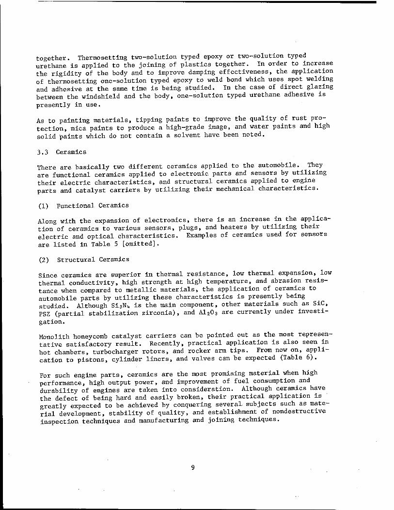
together. Thermosetting two-solution typed epoxy or two-solution typed urethane is applied to the joining of plastics together. In order to increase the rigidity of the body and to improve damping effectiveness, the application of thermosetting one-solution typed epoxy to weld bond which uses spot welding and adhesive at the same time is being studied. In the case of direct glazing between the windshield and the body, one-solution typed urethane adhesive is
presently in use.
As to painting materials, tipping paints to improve the quality of rust pro- tection, mica paints to produce a high-grade image, and water paints and high solid paints which do not contain a solvent have been noted.
3.3 Ceramics
There are basically two different ceramics applied to the automobile.^ They are functional ceramics applied to electronic parts and sensors by utilizing their electric characteristics, and structural ceramics applied to engine parts and catalyst carriers by utilizing their mechanical characteristics.
(1) Functional Ceramics
Along with the expansion of electronics, there is an increase in the applica- tion of ceramics to various sensors, plugs, and heaters by utilizing their electric arid optical characteristics. Examples of ceramics used for sensors are listed in Table 5 [omitted].
(2) Structural Ceramics
Since ceramics are superior in thermal resistance, low thermal expansion, low thermal conductivity, high strength at high temperature, and abrasion resis- tance when compared to metallic materials, the application of ceramics to automobile parts by utilizing these characteristics is presently being studied. Although Si3Ni,. is the main component, other materials such as SiC, PSZ (partial stabilization zirconia), and A1203 are currently under investi-
gation.
Monolith honeycomb catalyst carriers can be pointed out as the most represen- tative satisfactory result. Recently, practical application is also seen in hot chambers, turbocharger rotors, and rocker arm tips. From now on, appli- cation to pistons, cylinder liners, and valves can be expected (Table 6).
For such engine parts, ceramics are the most promising material when high performance, high output power, and improvement of fuel consumption and durability of engines are taken into consideration. Although ceramics have the defect of being hard and easily broken, their practical application is greatly expected to be achieved by conquering several subjects such as mate- rial development, stability of quality, and establishment of nondestructive inspection techniques and manufacturing and joining techniques.

CO ■P
td PL.
•pt 43 O S o +J
4 o P
CO o
•H
s M CÜ o m o 3 o
-r4
CO o
p.
NO
rH
■s E-t
Prac-
tical
appli-
cation
o O O o Ü
CO u
•H
1 U
o
<4-l o
co CJ
•H •P CO
•H Vl CD
■P Ü cd Vi cd
43 o
i i O CO CD u n i-t o Vi O co 3 O -rl CD Cd O CO Vl -P
o
3 ' ^ B cd 3 U m p. o
HJ .p CD CO
o
p 4-1 X 43 M ÖO-H
■H <D r4 &
o o O o o o o o o
cd Ö -H Ü u O co 3
43 -rt QJ Cd <J CO Vl -P
o o o O o o O o o o o
1 CO CD
UTI U cd co 3 CD CD cd
EC U -P
o o o o o O o o o o o
1 3 Vi cd 3 «H P.O
43 cd X -H H S <U W
o o o o O o Ü
feO 3 •H
CO 3 O X
cu 3 •H 43 U 3
■P H cd P.
M-l o
co
§ 55
u a)
■§ cd
CJ
3 o T* u CO
o o
•§ CO
3 o. •p CO
•H P*
«3 c •H Vi
3 O
■P CO •H PH
H 4)
■5 rH
u a
CD 4J cd
rH P.
•d cd
43
Vl a)
■3
rH r*. O
■p cd CD CO
CD
cd >
60 3
r-t P.
o rH o
CD >
rH cd >
« •H 3 öH
O >
rH cd >
Vl
-p
•H rH
a) >
rH cd >
e Vl cd
u 4> 44
CJ O Vl
CU >
rH cd >
IW CO
43 CO
s
rH cd at CD
rH cd CJ
•H 3 cd
43 CJ cu s
i p.
u ai ■P cd
4J V4 o p.
P CO 3 cd
•s
•3 rH O
«4-4 •H
■P CO rH
rH cd P cd u
60
a u cd <u
43
r« 3 cd Vi o
*3 o u M
P CJ <U 3 3 O
CJ
Vi o •p o u
cu 3 •H 43 Vl 3 H
3 o •H •P CO 3
o o
M
1 <D > rH cd >
4J CO
CO
bOg ÖCU ■H-P -t CO o >■ o CO u
P CO 3 cd
43 X w
■P CO
CO
3 •H VI cd <U pq
1 Vl <u p 3
Vl cu
Vl 3
43 Ü
10
4. Conclusions
The main materials used for automobiles have been described so far. An auto- mobile is a composite product of various industries. Therefore, materials which compose various parts have diversity. In addition to the improvement of conventional materials, there is the advent of so-called new elements and new materials. The new materials are not immediately substituted for conven- tional materials. The most important thing is to produce an automobile that has the functions and performance expected by the user and also value added to low cost. It is necessary to master the materials, including the study of production technology.
As seen in the past, from now on it is necessary to advance technological development in cooperation between material makers and car makers and to make their efforts put on the market in a timely manner an automobile which matches the user's demand.
BIBLIOGRAPHY
1. Tuschiya, T., JOURNAL OF THE SOCIETY OF AUTOMOTIVE ENGINEERS OF JAPAN, Vol 40 No 6, 1986, p 637.
2. Japan Transportation Policy Study Meeting, Future Technique Committee, the University of Michigan; U.S. Automotive Industry Trends for the 1980s. Arthur Andersen & Co., July 1981.
3. MATERIAL CYCLOPEDIA, Industrial Investigation Committee.
4. Ide, T., The Society of Precision Machine, lecture summary collection
1984.
5. NIKKEI MECHANICAL, pp 2, 24
6. Chogin, Division of Investigation, Investigation Monthly Report-, No 192^
7. Ide, T., MATERIAL FORLAM (?), No 3, 1986, p IB.
8. Federhenn, M. , SITEV T85 Symposium, 1985.
9. Holtzberg, M.W., 40th Annual Conference RP/C, SPI, session 14-B, 1985.
10. Miyayama, M., JOURNAL OF THE SOCIETY OF AUTOMOTIVE ENGINEERS OF JAPAN, Vol 40 No 8, 1986, p 980.
11. Miyamura, N., NIKKEI MECHANICAL, 1985, pp 5, 6.
20,149/9365 CSO: 4306/3677
11
ADVANCED MATERIALS
STATUS OF MATERIALS FOR MAGNETOOPTICAL ELEMENTS DISCUSSED
Tokyo KINO ZAIRYO in Japanese Feb 87 pp 26-34
[Article by Naoki Koshizuka, head of Magnetic Material Research Laboratory, Material Department, Institute of Electronics and Technology; and Takashi Okuda and Koji Ando, staff members of Magnetic Material Research Laboratory, Material Department, Institute of Electronics and Technology]
[Text] With the development of the optical information communication system, there is a growing interest in magnetooptical elements such as the optical isolator, etc., which are indispensable for the stabilization of a light source. In this text, the structure, physical properties, preparation and processing technologies, and application possibilities of the magnetic garnet, which has attracted attention as a magnetooptical element material, will be explained. Explanations will also be made on the status of the phase-matching method and fine-processing technology for the waveguide mode which is important to the development of waveguide-type magnetooptical element.
1. Introduction
In the midst of a period in which communication and data processing systems utilizing light are progressing, there is a growing interest in irreversible optical elements (optical isolator, optical circulator, etc.) and the opti- cal switch.1»2 In the realization of such light-functioning elements, the magnetooptical effects peculiar to the magnetic material, especially the Faraday effect, play important roles. The Faraday effect is a phenomenon in which the plane of polarization rotates when a linear polarized light passes through a magnetized material.3 The rotating direction of the plane of polarization differs according to the parallel and nonparallel difference of the direction of magnetization against the direction the light is progressing. A one-directional optical element can be made by utilizing this property. Moreover, the Faraday effect and the magnetic Kerr effect, which is a rota- tion phenomenon of the plane of polarization against the reflection light, are used for reading the photomagnetic memory bit.
The most important characteristic in a magnetooptical material is that the Faraday rotational coefficient 8F be large and the absorption coefficient a be small; i.e., the performance index | 9F |/a be high. Moreover, it is necessary that the crystal be optically Isotropie and have a strong magnetism
12
at room temperature. Attention will be directed here on the magnetic garnet which has a high-performance index in the near-infrared spectrum and is most promising as a medium for the magnetooptical elements, and the physical properties, preparation and processing methods, and the application possi- bilities of the magnetic garnet will be introduced.
2. Various Physical Properties of the Magnetic Garnet Film
2.1 Structure and Magnetism
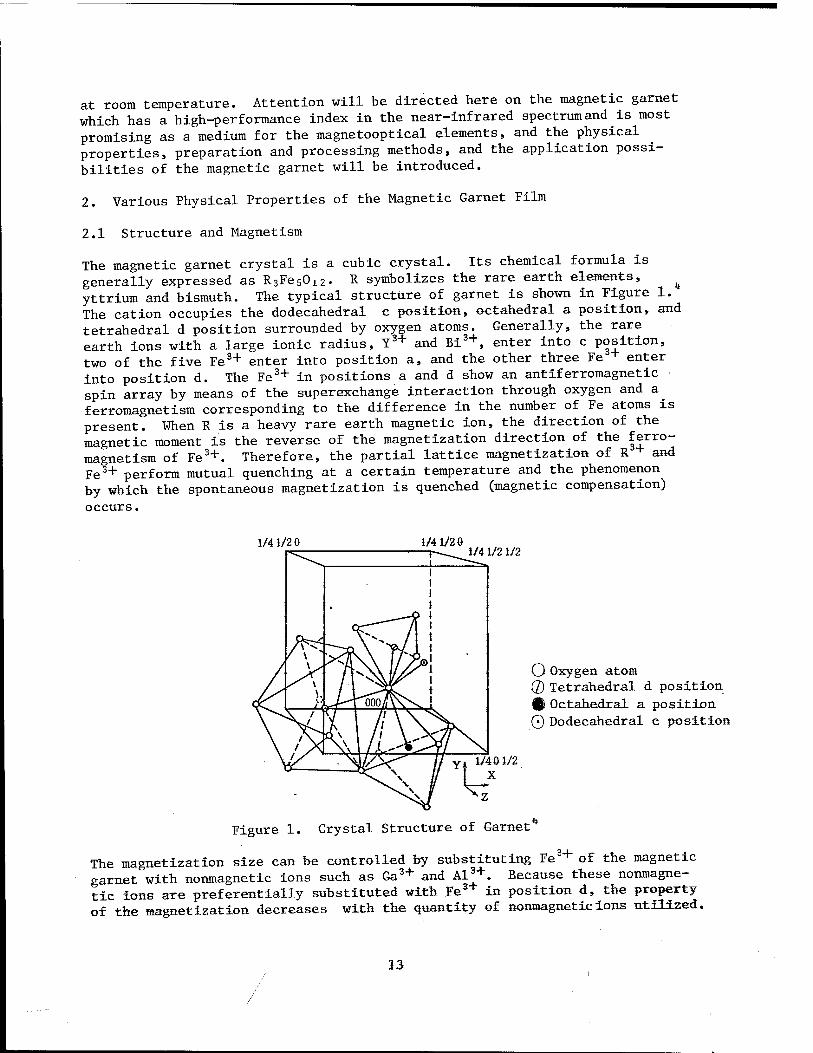
The magnetic garnet crystal is a cubic crystal. Its chemical formula is generally expressed as R3Fe5Ol2. R symbolizes the rare earth elements, ^ yttrium and bismuth. The typical structure of garnet is shown in Figure 1. The cation occupies the dodecahedral c position, octahedral a position, and tetrahedral d position surrounded by oxygen atoms. Generally, the rare earth ions with a large ionic radius, Y3* and Bi3+, enter into c position, two of the five Fe3+ enter into position a, and the other three Fe + enter into position d. The Fe3+ in positions a and d show an antiferromagnetic spin array by means of the superexchange interaction through oxygen and a ferromagnetism corresponding to the difference in the number of Fe atoms is present. When R is a heavy rare earth magnetic ion, the direction of the magnetic moment is the reverse of the magnetization direction of the |erro- magnetism of Fe3+. Therefore, the partial lattice magnetization of R + and Fe3+ perform mutual quenching at a certain temperature and the phenomenon by which the spontaneous magnetization is quenched (magnetic compensation)
occurs.
1/41/2 0 1/4 1/20 1/4 1/2 1/2
O Oxygen atom © Tetrahedral d position Q Octahedral a position 0 Dodecahedral c position
Figure 1. Crystal Structure of Garnet
The magnetization size can be controlled by substituting Fe3+ of the magnetic garnet with nonmagnetic ions such as Ga3+ and Al3+. Because these nonmagne- tic ions are preferentially substituted with Fe3+ in position d, the property of the magnetization decreases with the quantity of nonmagnetic ions utilized.
13
In the optical elements using the garnet film, whether the easy magnetization axis is in the plane or perpendicular to the plane, the symbol and size of the magneticanisotropy energy is also important. Research on magnetic anisotropy is advanced on the garnet film for the magnetic bubble memory grown by the liquid phase epitaxy (LPE) method. The three main factors of the magnetic garnet are: 1) shape anisotropy; 2) stress-induction magnetic anisotropy; and 3) growth-induction magnetic anisotropy. In a magnetic thin film, the effect of shape anisotropy works to face the magnetization towards the in plane. The stress-induction magnetic anisotropy is generated through the contrary effect of the magnetic strain due to the stress generated by the lattice nonconformity of the film and substrate. The growth-induction magnetic anisotropy is generated by the uneven distribution of different kinds of atoms in the LPE growth process and it relies upon the combination and growth con- dition of rare earth atoms. For example, when one of the rare earth atoms is either Y or Lu, a uniaxial magnetic anisotropy is induced by the combination of Pr, Nd, Sm, Eu, and Tb and it is known that the greater the difference in the ion radii of the different atoms, the greater the anisotropic energy.5
The actual magnetic anisotropy is a combination of these factors.
2.2 Magnetooptical Characteristics
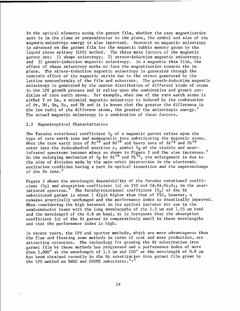
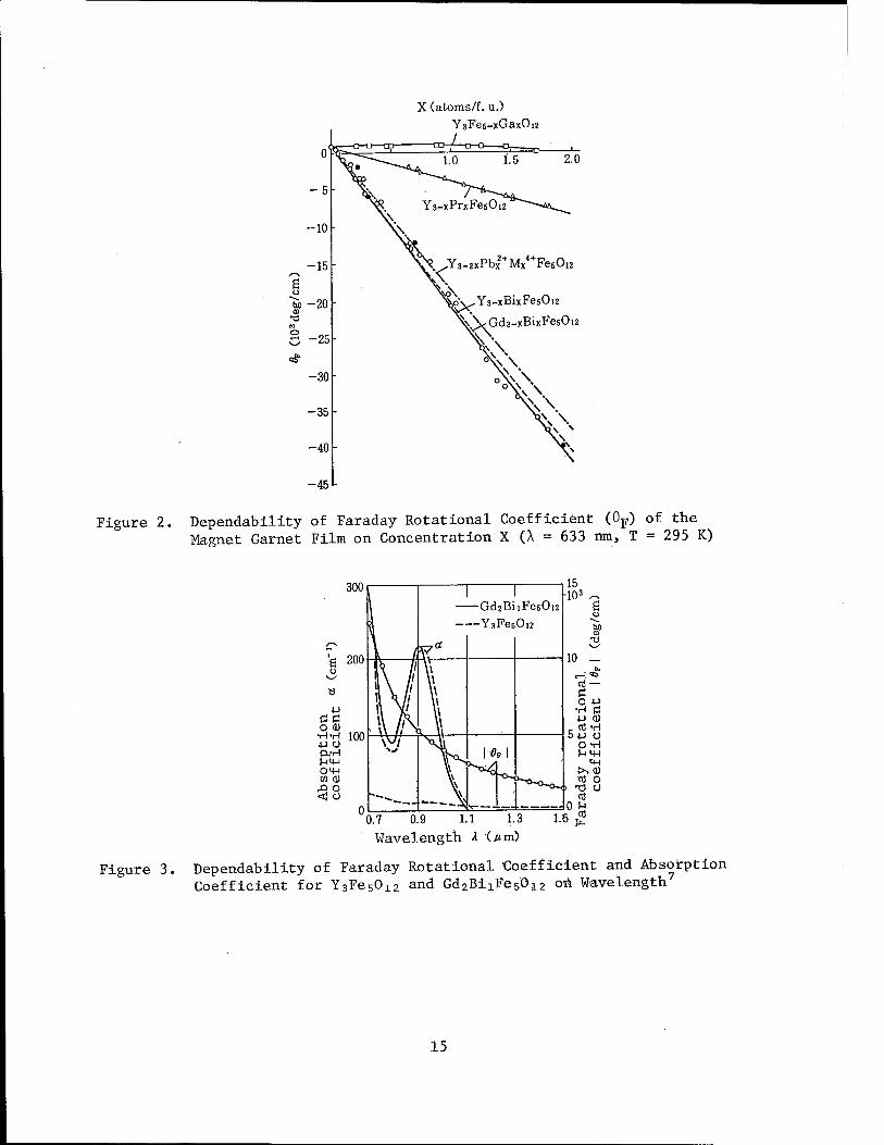
The Faraday rotational coefficient Op of a magnetic garnet relies upon the type of rare earth ions and nonmagnetic ions substituting the magnetic atoms. When the rare earth ions of Pr3+ and Nd and heavy ions of Bi + and Pb3+
enter into the dodecahedral position c, symbol Op of the visible and near- infrared spectrums becomes minus as shown in Figure 2 and the size increases.6
On the enlarging mechanism of Op by Bi3+ and Pb +, the enlargement is due to the size of division made by the spin orbit interaction in the electronic excitation condition having a part in optical transition and the superexchange of the Fe ions.6
Figure 3 shows the wavelength dependability of the Faraday rotational coeffi- cient (8p) and absorption coefficient (a) on YIG and GdzBixFesO^ in the near- infrared spectrum.7 The Faraday rotational coefficient (Op) of the Bi substituted garnet is about 1 digit higher than that of YIG, however, a remains practically unchanged and the performance index is drastically improved. When considering the high interest in the optical isolator for use in the semiconductor laser with the long wavelengths of the 1.3 ym and 1.55 Um band and the wavelength of the 0.8 ym band, it is fortunate that the absorption coefficient (a) of the Bi garnet is comparatively small in these wavelengths and that the performance index is high.
In recent years, the LPE and sputter methods, which are more advantageous than the flux and floating zone methods in terms of cost and mass production, are attracting attention. The technology for growing the Bi substitution iron garnet film by these methods has progressed and a performance index of more than 1,000° at the wavelength of 1.3 ym and 100° at the wavelength of 0.8 ym has been obtained recently in the Bi substitution iron garnet film grown by the LPE method on NdGG and GGGMZ substrates.8»9
14
X (atoms/f. u.) YsFes-xGaxOiü
-45
Figure 2. Dependability of Faraday Rotational Coefficient (8F) of the Magnet Garnet Film on Concentration X (X = 633 nm, T = 295 K)
300 1 1 15
-103 ^ Gd2BiiFe60i2 ß YaFesOiz txO
T3
'e 2oo J-7Ä
10 _ [I. ft /' 1\ //
\\ U
« i\/' V cd — C
H A/' \t O +J 4-1 I\ Yi \l •H a
a c \\ /.s. \l ■u a) o aj •H-rl 100 \ /,' V c cd -H
5+j o O -H W
CX-H I'M u m S-it-) V. ^o^ ^i M-l om \\ ■>><u CD OJ \\ cd o
rQ O I t) o <J o V cd
u * -~^ >; _ : _- o a
3.7 0.9 1.1 1.3 1. c cd
Wavel ength A O im )
Figure 3. Dependability of Faraday Rotational Coefficient and Absorption Coefficient for Y3Fe5Ol2 and Gd2Bi1Fe5012 on Wavelength
7
15
2.3 Optical Mode Conversion and Double Refraction
Because the refractive index (nj) of the magnetic garnet film is bigger than the refractive index (ns) of the nonmagnetic garnet used as the substrate, it also excels as an optical waveguide medium. Various functions are realized in the waveguide-type optical functioning device by utilizing the mode of conversion made by the magnetooptical effect between the TE mode propagating within the thin film (electric vector vibrating in parallel to the film plane) and the TM mode (magnetic vector vibrating in parallel to the film plane). The conversion efficiency R(L) is expressed by the following equa- tion 10
R(D- 0p
0F2 + G*/?/2)2 sin2(VöF
2 + (J/?/2)2-L) (1)
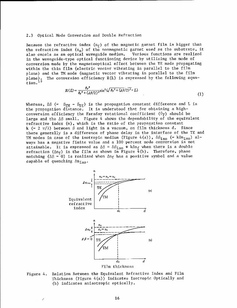
Whereas, Aß (= ßjM - ßpE) is the propagation constant difference and L is the propagation distance. It is understood that for obtaining a high- conversion efficiency the Faraday rotational coefficient (0p) should be large and the Aß small. Figure 4 shows the dependability of the equivalent refractive index (n), which is the ratio of the propagation constant k (= 2 IT A) between ß and light in a vacuum, on film thickness d. Since there generally is a difference of phase delay in the interface of the TE and TM modes in case of the isotropic medium (Figure 4(a)), Aßiso (= kAniso) al- ways has a negative finite value and a 100 percent mode conversion is not attainable. It is expressed as Aß = Aßj_so + kAnj when there is a double refraction (Anf) in the film as shown in Figure 4(b). Therefore, phase matching (Aß = 0) is realized when Anj has a positive symbol and a value capable of quenching lm±so.
Ann.
Equivalent refractive
index
(a)
Am
Aß=Q (b)
Film thickness
Figure 4. Relation Between the Equivalent Refractive Index and Film Thickness (Figure 4(a)) Indicates Isotropic Optically and (b) indicates anisotropic optically.
r 16
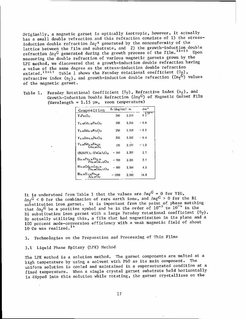
Originally, a magnetic garnet is optically isotropic, however, it actually has a small double refraction and this refraction consists of 1) the stress- induction double refraction Anf
s generated by the nonconformity of the lattice between the film and substrate, and 2) the growth-inductionRouble refraction AnfG generated during the growth process of the film. Upon measuring the double refraction of various magnetic garnets grown by the LPE method, we discovered that a growth-induction double refraction having a value of the same degree as the stress-induction double refraction existed.11-13 Table 1 shows the Faraday rotational coefficient (0g), refractive index (nf), and growth-induction double refraction (Enf
G) values of the magnetic garnet.
Table 1. Faraday Rotational Coefficient (9F), Refractive Index (nf), and Growth-Induction Double Refraction (AnfG) of Magnetic Garnet Film (Wavelength =1.15 ym, room temperature)
■Composition Ot (deg/crr ) m JmG
YsFesOiz 240 2.213 o.ru" Y2.7BGdo.22FesOl2 290 2.210 -0.8
Yz.85Ndo.i5Fe5Oi2 250 2,213 -0.7
Y2.76Smo.2<FesOi2 225 2,212 -0.4
Y2.64Ndo. 36Fe<. 25 Gao.9sOi2
115 2,177 - 1.0
(BiNdY)3 (FeGa)50,2 -310 2,207 2.7
Bio.73Pro.3<Yb2.23 Fes. 6sGai. 02O12
-760 2,231 2.7
Bio. 6sGdo.87Lu 1.81 Fe3.96Gao.7iOi2
-580 2.244 4.2
Bio.76Y2.24Fe4.43 AI0.57O12
- 1390 2,242 14.8
It is understood from Table 1 that the values are AnfG = 0 for YIG, Anf
G < 0 for the combination of rare earth ions, and AnfG > 0 for the Bi substitution iron garnet. It is important from the point^f phase matching that Anf
G be a positive symbol and be in the order of 10" to 10 in the Bi substitution iron garnet with a large Faraday rotational coefficient (6F). By actually utilizing this, a film that had magnetization in its plane and a 100 percent mode-conversion efficiency with a weak magnetic field of about 10 Oe was realized.lk
3. Technologies on the Preparation and Processing of Thin Films
3.1 Liquid Phase Epitaxy (LPE) Method
The LPE method is a solution method. The garnet components are melted at a high temperature by using a solvent with PbO as its main component. The uniform solution is cooled and maintained in a supersaturated condition at a fixed temperature. When a single crystal garnet substrate held horizontally is dipped into this solution while rotating, the garnet crystallizes on the
17
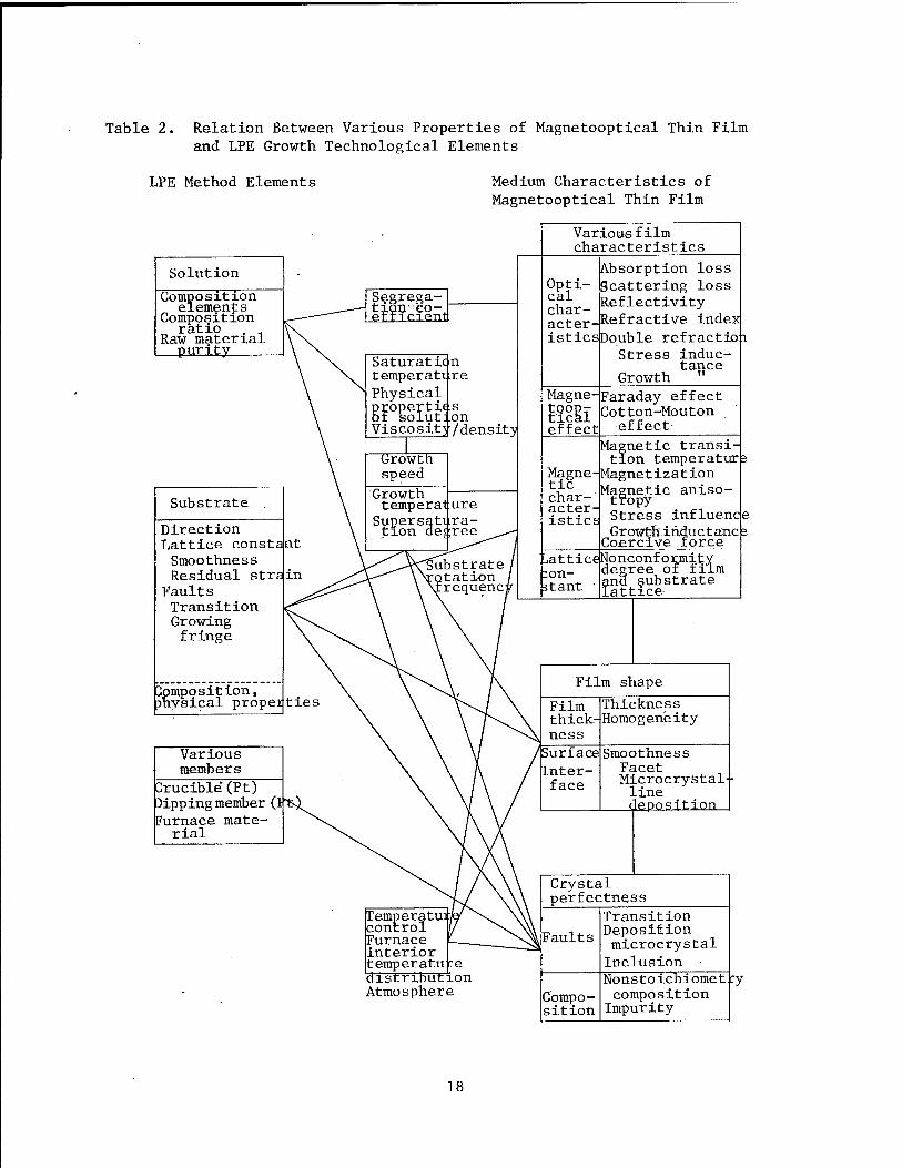
Table 2. Relation Between Various Properties of Magnetooptical Thin Film and LPE Growth Technological Elements
LPE Method Elements Medium Characteristics of Magnetooptical Thin Film
Solution
Composition elements
Composition ratio . ,
Raw material purity
Substrate
Direction Lattice const Smoothness Residual sti Faults Transition Growing fringe
composition, physical propeities
Various members
Crucible(Pt) Dipping member ('. Furnace mate- rial
Temperatur control Furnace interior temperature distribution Atmosphere
Various film characteristics
Absorption loss Scattering loss Reflectivity .Refractive index
•s[Double refractiop Stress induc-
Growth tance
■Faraday effect Cotton-Mouton
effect
Magnetic transi- tion temperatur^
-Magnetization Magnetic aniso- tPopy Stress influence Growth ihdu c t äncE Coercive force
LcejNonconformitY degree of film and substrate lattice
Film shape
Thickness Homogeneity
Smoothness Facet Microcrystal line deposition
Crystal perfectness
Transition Deposition microcrystal Inclusion Nonstoichiomet composition Impurity
18
substrate and an epital crystal growth is made in conformity with the sub- strate direction. This method is called the isothermal-horizontal-substrate- rotational dipping method.15 Since a good quality film with homogeneity in both composition and film thickness is available by good reproducibility, this method is the most widely used.16»17
Table 2 shows the relation among the elements of the LPE method and the medium characteristics of the magnetooptical thin-film elements. Besides the three factors of solution, substrate, and various members, temperature con- trol of the furnace, temperature distribution in the furnace, and atmosphere are also important factors.
The various properties of a film are decided by the film composition. The film composition is adjusted by the solution composition and growth tempera- ture. The shape of the film thickness and surface condition is controlled mainly by the growth speed.
The selection of the substrate is also important for obtaining a film that will have expected properties. The crystal direction dependability of vari- ous characteristics is decided by the substrate direction. In a film for an optical element, it is also necessary to give enough consideration to the optical characteristics (refractive index, optical absorption, etc.) of the substrate. The perfection of the crystals of a film such as absence of crystal fault, etc., are directly linked to the quality of the substrate.
Gd3Ga50i2 (GGG) and (CdCa)3 (GaMzZr)50i2(GGMZ) which are transparent from the visible spectrum to the near-infrared spectrum, and Sm2Ga50i2(SmGG) and Nd3Ga5012(NdGG), which have a weak absorption in the visible spectrum, are used for the substrate materials. Because each of the materials has a different lattice constant, selection is made to promote conformity with the lattice constant of the film.
Pb used in the solvent and Pt used in the crucible are typical impurity elements and the quantity of impurities is also related to the growth speed. Since the valence of Pb is either +2 or +4, it causes nonstoichiometry com- position. In other words, when the valence of Fe is shifted from +3 to +4 or from +3 to +2, an oxygen fault is generated and an increase in optical absorption occurs. Moreover, the lattice constant of the film is greatly changed due to the larger ion radius. On the other hand, because the mix- ing quantity depends remarkably on the growth temperature, fine adjustments are made on the refractive index and the degree of conformity of the lattices of the film and substrate, and the preparation of a higher mode absorption film for a single-mode waveguide is made by controlling the growth temperature.
3.2 Sputter Method
The LPE method has these weakpoints: The realization of a large area is difficult using a single crystal substrate and the lattice constant of the film is restricted.
19
The special features of the sputter method are: 1) it is a dry process; 2) it is a nonthermal equilibrium process; and 3) use of a glass substrate is possible. Because it is possible in a dry-process method to integrate films of different materials continuously and to provide fine processing on the film, this method is drawing attention as an optical integrated circuit technology. The second feature makes possible low-temperature film prepara- tion and a large-quantity substitution of Bi which has a large ion radius. The third quality attracts attention from the standpoint of photomagnetic memory technology. The film becomes polycrystallized when a glass substrate is used, but there is no restriction in the lattice constant of the film. Moreover, when taking into consideration that it is cheap for the GGG sub- strate and that making the target large is comparatively easy, the realiza- tion of a large-area film with a large quantity of Bi substitution can be expected.19 The sputter method that can produce a film with a large quantity of Bi substitution is rapidly progressing.
The sputter methods generally used are the high-frequency bipolar method, DC counter target method,20 high-frequency planar magnetron method,21 and ion beam type method.20-22
19
Ion gun 2
Ion gun 1
M. F. C. •Ar gas
in M.F.C. -—Oz'gas
M. F. C.
Ar gas
T~ Cooling water
Shutter
D.Pt5£:R.P
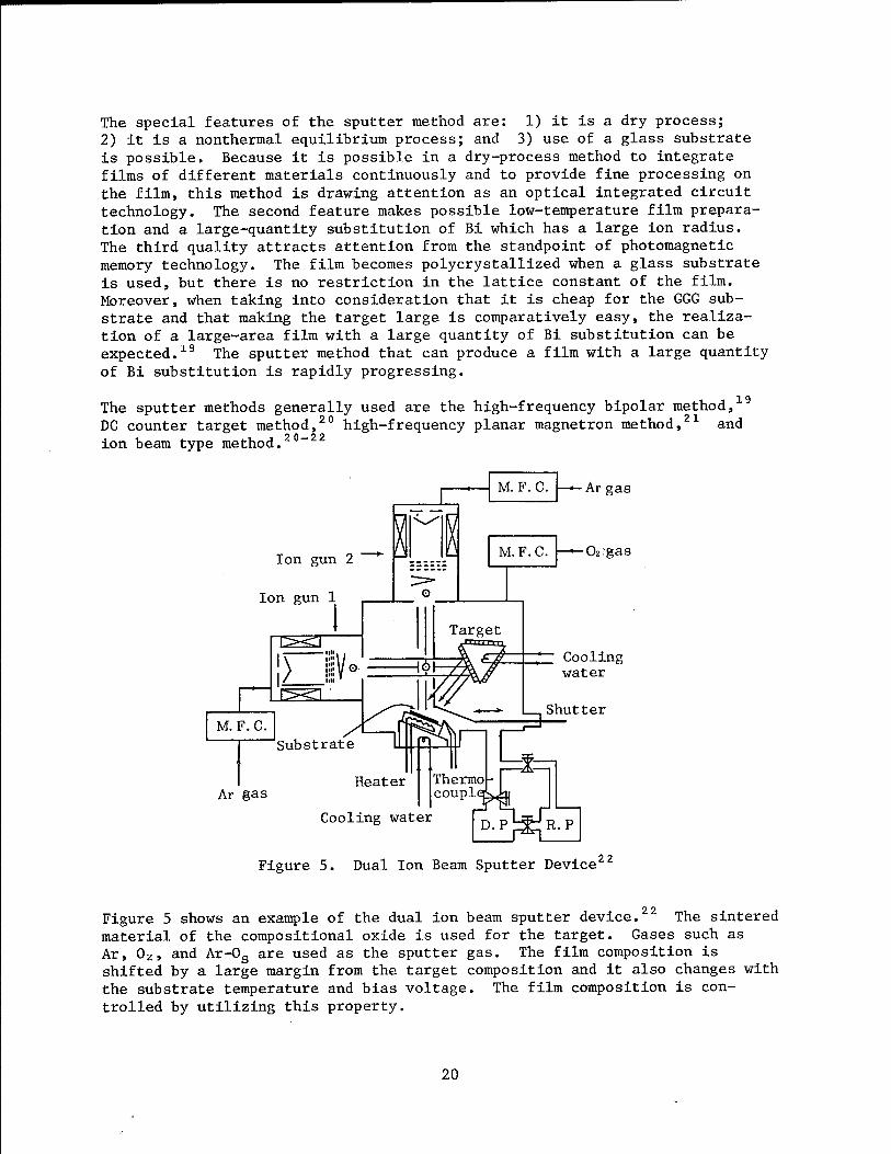
Figure 5. Dual Ion Beam Sputter Device 22
Figure 5 shows an example of the dual ion beam sputter device. The sintered material of the compositional oxide is used for the target. Gases such as Ar, 0Z, and Ar-Os are used as the sputter gas. The film composition is shifted by a large margin from the target composition and it also changes with the substrate temperature and bias voltage. The film composition is con- trolled by utilizing this property.
20

The substrate must be heated in the range of 700-800°C for crystallizing the film while accumulation and obtaining the garnet phase. The maintenance of a large area at a uniform high temperature in a vacuum presents techno- logical difficulties. Therefore, there are many cases where the substrate temperature is less than 500°C and amorphous film is available. Crystalliza- tion of a film is done by heating it in air. In this case, an epitaxial growth is made when the substrate is a single crystal and polycrystallization is made when the substrate is glass. The temperature of crystallization is lowered when Bi substitution increases and crystallization becomes possible during accumulation. It has been reported that the crystallization tempera- ture during accumulation is lowered to 520°C and the heat treatment crystallization temperature after the accumulation is 650°C. There is also a report on a sputter film which has a magnetooptical performance and bubble magnetic domain dynamic characteristics equal in quality to LPE film. On the other hand, the excellent values of the coercive force (55 Oe) and crystal diameter (0.1 ym) have been obtained for the photomagnetic memory polycrystalline film.
3.3 Fine Processing Technology
Ion drive-in and ion milling had been known as fine-processing technologies for magnetic garnet film. The development of a new fine-processing tech- nology suited for the preparation of waveguide-type magnetooptical elements has taken place in recent years.
The angle created by the magnetic moment direction and by the direction the light is progressing has an important meaning for magnetooptical elements. As seen in the example of the optical isolator to be described later, there are times when a structure that can change the magnetic moment direction of the magnetooptical element on a simple substrate is necessary. The local heat treatment using the Ar+ laser beam (laser annealing) has been developed for the purpose of changing the magnetic moment direction of the magnetic garnet film locally.21* The magnetic domain photo shown in Figure 6 indicates that the magnetic moment direction in the central part that has been subjected to heat treatment by the laser beam is unlike its surroundings.
100 jum
Figure 6. Magnetic Domain Pattern When Changing the Magnetization Direction Gärnet Film by Laser Annealing
21
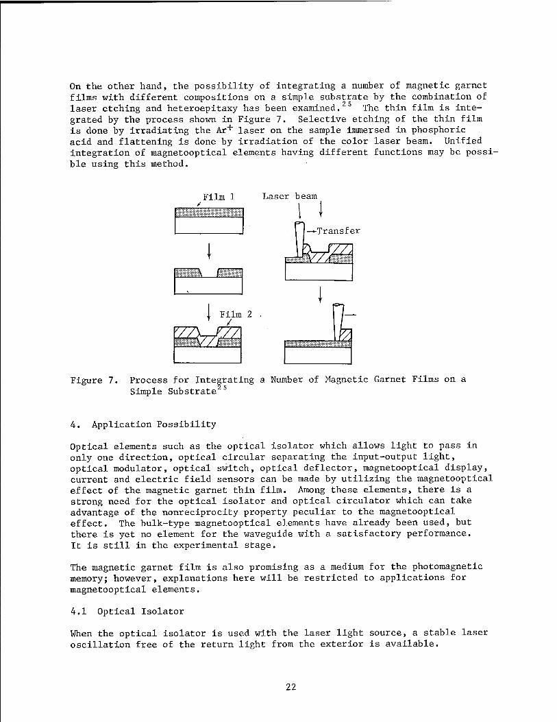
On the other hand, the possibility of integrating a number of magnetic garnet films with different compositions on a simple substrate by the combination of laser etching and heteroepitaxy has been examined. 5 The thin film is inte- grated by the process shown in Figure 7. Selective etching of the thin film is done by irradiating the Ar+ laser on the sample immersed in phosphoric acid and flattening is done by irradiation of the color laser beam. Unified integration of magnetooptical elements having different functions may be possi- ble using this method.
Film 1 Laser beam
r\ i—
I mzm,
Film 2 . /
Transfer
Figure 7. Process for Integrating a Number of Magnetic Garnet Films on a Simple Substrate 25
4. Application Possibility
Optical elements such as the optical isolator which allows light to pass in only one direction, optical circular separating the input-output light, optical modulator, optical switch, optical deflector, magnetooptical display, current and electric field sensors can be made by utilizing the magnetooptical effect of the magnetic garnet thin film. Among these elements, there is a strong need for the optical isolator and optical circulator which can take advantage of the nonreciprocity property peculiar to the magnetooptical effect. The bulk-type magnetooptical elements have already been used, but there is yet no element for the waveguide with a satisfactory performance. It is still in the experimental stage.
The magnetic garnet film is also promising as a medium for the photomagnetic memory; however, explanations here will be restricted to applications for magnetooptical elements.
4.1 Optical Isolator
When the optical isolator is used with the laser light source, a stable laser oscillation free of the return light from the exterior is available.
22

Therefore, the optical isolator has promise as a future large-capacity and high-speed optical communication system. It is indispensable to a variety of sophisticated optical systems, including the coherent optical communica- tion.
The technological difficulty of realizing the waveguide-type optical isolator is due to the fact that the intrinsic modes of the light propagating in a thin film are of the TE and TM modes. The first problem is in what manner should the phase matching (Aß = 0) necessary for obtaining a high mode conver- sion efficiency between the two modes be realized. Besides the experiment of providing a double refraction to the film itself, experiments utilizing the waveguide that periodically inverses the partial lattice magnetization, artificial anisotropic waveguide,27 bonding of the magnetic garnet film and double refraction crystal,20 and multilayer structure waveguide29 have been undertaken on this problem.
The second problem on the waveguide-optical isolator is the need for the tech- nology to prepare a structure capable of converting the TE mode into the TM mode in only one direction. There have also been various propositions and this directional mode converter has been trial manufactured. An example is shown in Figure 8. When the magnetization M direction forms a waveguide by combining the domain parallel to the light progressing direction (nonreci- procity domain) and the domain perpendicular to the light progressing direc- tion (reciprocity domain), an element in which the TE mode is converted into the TE mode for light in only one direction can be created.2' ° Since the metal film serves as a polarizer for passing the TE mode only, the return light from the right converted into the TM mode is intercepted and becomes the isolator which would have locally different magnetization distribution. Experiments have been done on the high-precision control of the magnetiza- tion direction by applying laser annealing2h and laser etching described earlier.
Metal, film
Magnetic garnet film
GGG substrate
ecxprocxty domain XCotton- Mouton effect)
Nonreciprocity domain (Faraday
effect)
Figure 8. Structure of Waveguide-Type Optical Isolator
4.2 Other Elements
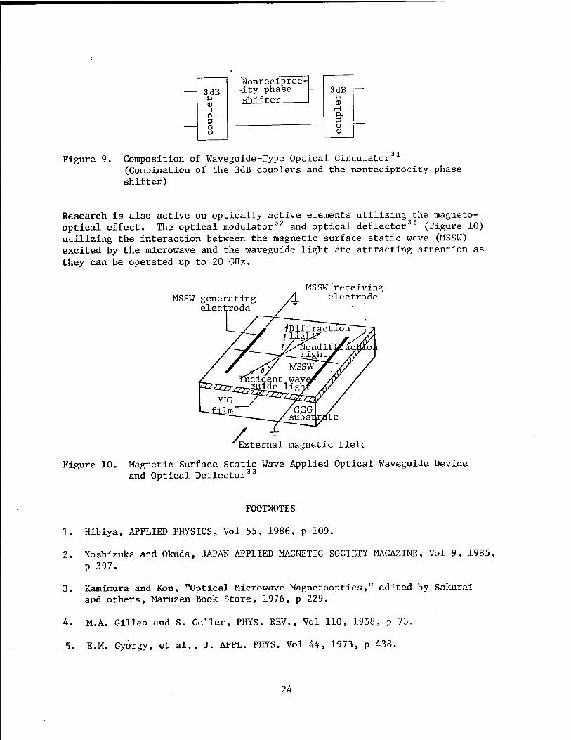
As shown in Figure 9, the waveguide-type optical circulator is made by combin- ing the nonreciprocity phase shifter utilizing the magnetooptical effect and the 3dB coupler.31 However, the fine processing technology, etc., for realiz- ing this structure is poor and trial-manufacture has not yet been done.
23
3 dB U a)
.H P<
o o
Nonreciproc- ity phase fihift"pr
3 dB
0) H P-
o i Ü
.31 Figure 9. Composition of Waveguide-Type Optical Circulator' (Combination of the 3dB couplers and the nonreciprocity phase shifter)
Research is also active on optically active elements utilizing the magneto- optical effect. The optical modulator32 and optical deflector33 (Figure 10) utilizing the interaction between the magnetic surface static wave (MSSW) excited by the microwave and the waveguide light are attracting attention as they can be operated up to 20 GHz.
MSSW generating electrode
MSSW receiving electrode
on
External magnetic field
Figure 10. Magnetic Surface Static Wave Applied Optical Waveguide Device and Optical Deflector 33
FOOTNOTES
1. Hibiya, APPLIED PHYSICS, Vol 55, 1986, p 109.
2. Koshizuka and Okuda, JAPAN APPLIED MAGNETIC SOCIETY MAGAZINE, Vol 9, 1985, p 397.
3. Kamimura and Kon, "Optical Microwave Magnetooptics," edited by Sakurai and others, Maruzen Book Store, 1976, p 229.
4. M.A. Gilleo and S. Geller, PHYS. REV., Vol 110, 1958, p 73.
5. E.M. Gyorgy, et al., J. APPL. PHYS. Vol 44, 1973, p 438.
24

6. P. Hansen and J.-P. Krumme, THIN SOLID FILMS, Vol 114, 1984, p 69.
7. H. Takeuchi, S. Ito, I. Mikami, and S. Taniguchi, J. APPL. PHYS., Vol 44, 1973, p 4789.
8. T. Hibiya, T. Ishikawa, and Y. Ohta, IEEE TRANS. MAG., MAG-22, 1986, p 11.
9. Yokoyama, Takahasi, and Koshizuka, JAPAN APPLIED MAGNETIC SOCIETY MAGAZINE, Vol 10, 1986, p 165.
10. G. Hepner, J.P. Castera, and B. Desormiere, AIP CONF. PROC, Vol 29, 1975, p 659.
11. T. Okuda, N. Koshizuka, A. Murata, Y. Yokoyama, and K. Ando., J. APPL. PHYS., Vol 55, 1984, p 2176.
12. K. Ando, N. Takeda, T. Okuda, and N. Koshizuka, Ibid., Vol 57, 1985, p 718.
13. Koshizuka, Yokoyama, Ando, and Okuda, JAPAN APPLIED MAGNETIC SOCIETY MAGAZINE, Vol 10, 1986, p 155.
14. A. Murata, N. Koshizuka, T. Okuda, K. Ando, A. Ito, and K. Kawanishi, IEEE TRANS. MAG., MAG-21, 1985, p 1657.
15. H.J. Levinstein, S.J. Licht, R.W. Landorf, and S.L. Blank, APPL. PHYS. LETT., Vol 19, 1972, p 486.
16. J.W. Nielsen, IEEE TRANS. MAG., MAG-12, 1976, p 327.
17. Okuda, Koshizuka, Murata, and Ando, 38th Japan Applied Magnetic Society Research Study Meeting 38-9, 1985.
18. E. Sawatzky and E. Kay, J. APPL. PHYS., Vol 39, 1968, p 4700.
19. Gomi, Tanida, and Abe, Eighth Japan Applied Magnetic Society Scientific Lecture Collection of Epitome, 13aB-6, 1985.
20. K. Ishii, Y. Hoshi, M. Naoe, and S. Yamanaka, PROC. INT. CONF. FERRITES, 1980, p 831.
21. J.-P. Krumme, V. Doormann, and P. Willich, J. APPL. PHYS., Vol 57, 1985, 3885.
22. T. Okuda, K. Hayashi, N. Koshizuka, and Y. Yokoyama, ABSTRACT OF ICMFS- 11, CC-11, 1985.
23. Shono, Koshina, and Ogawa, Electricty Society Research Study Meeting Data, MAG-85-82, 1985.
25

24. K. Ando, Y. Yokoyoma, T. Okuda, and N. Koshizuka, J. MAGN. MAGN. MATER., Vol 35» 1983, p 350.
25. K. Ando, N. Takeda, and N. Koshizuka, APPL. PHYS. LETT., Vol 46, 1985, p 1107.
26. R. Wolfe, et al., Ibid., p 817.
27. Mizttmoto and Naito, ELECTRONIC COMMUNICATION SOCIETY MAGAZINE (c), J66-C, 1983, p 454.
28. S.T. Kirsch, et al., J. APPL. PHYS., Vol 52, 1981, p 3190.
29. A. Shibukawa and M. Kobayashi, APPL. OPT., Vol 20, 1981, p 2444.
30. S. Yamamoto and T. Makimoto, J. APPL. PHYS., Vol 45, 1974, p 882.
31. F. Auracher and H.H. Witte, IEEE TRANS. MICROWAVE THEORY AND TECH., MTT-30, 1982, p 922.
32. A.D. Fisher, J.N. Lee, E.S. Gaynor, and A.V. TVeten, APPL. PHYS. LETT., Vol 41, 1982, p 779.
33. D. Young, W. Chen, and C.S. Tsai, 1984 ULTRASONIC SYMPOSIUM PROC, Vol 2, 1984, p 168.
20158/9365 CSO: 4306/7554
26
ADVANCED MATERIALS
BASIC RESEARCH FOR PROMOTION OF CERAMICS DISCUSSED
Tokyo CERAMICS JAPAN in Japanese Dec 86 pp 1,090-1,094
[Article by Osami Kamigaito, Toyota Central Research and Development Laboratories, Inc.]
[Excerpts] I was not inclined to talk on the difficult subject of promotion of ceramics science and technology, but circumstances forced me to deliver a lecture on the subject. I hope you will favor me with your comments on this talk.
Despite the current boom in ceramics, the industry is not able to sustain the present numbers of researchers in the field. However, the picture is not totally negative.
We believe that ceramics is a valuable material for the present and the future because it has two distinguished characteristics. [Table 1-A omitted]
One of these characteristics involves its chemical and electronic functions. Plastic has a hydrogen bond or a covalent bond. The characteristics of metals are also clear. In comparison with plastics and metals, the bonding form of plastics is diversified} therefore-, plastics exhibit many functions. I believe plastics are far superior to metals in respect to diversity of functions.
The other characteristic relates to observing ceramics as a structural material. In precision instruments, high temperature instruments, wear resistance instruments, corrosion resistance instruments, and robots, it is necessary to enhance the characteristics possessed by metals and plastics up to their utmost limits. In practically all cases, ceramics is positioned in this limit. Therefore, it is believed that in comparison with plastics and metals, ceramics excels in parts for these abovementioned instruments. Although the present industrial scale on ceramics is small, these character is tisc will, I believe, insure that ceramics will become invaluable material for the future.
Now, in considering what can be made through clever use of ceramics having such characteristics, I believe that the realization of an industrial system which had been impossible to achieve by plastics and metals will become
27

possible. I also think it might not be possible for ceramics to outstrip metals and plastics in individual parts manufacture; however, ceramics are capable of substituting for a system in some instances.
In that case, when comparing system costs, ceramics may be less expensive even though the cost is higher for parts. However, the existing circumstances are not as simple as mentioned. Problems are shown in Table 1-B. [omitted]
Ceramics have not had a long history of use. This is especially so for structural materials. Many electronic materials using ceramics have been sold and experiences have accumulated; however, when stress is added to the ordinary use situation, information accumulated through experience will become important.
Another factor is that there are many unresolved issues of basic rules and quantitative expressions that link sought-after characteristics and characteristics of ceramics. At present, pertinent material selection is difficult, considering the need to manufacture parts having certain characteristics. Some industries are also experiencing problems on this point. Information about the mechanism of functions of ceramics is not well known at this time.
Moreover, the belated start in materials science is conspicuous in the area of structural materials. The delay on the establishment of defects science has also been conspicuous.
It is considered that 50 percent of the material controls the mechanical characteristics of ceramic and about 50 percent controls defect characteristics. In contrast to this, with metals and plastics, the choice of material determines the characteristics; therefore materials science exerts substantial influence on them. In the case of ceramics, however, materials science will not be the solution to the problem.
When ceramics are used in preparing structural parts, manufactured parts are at the core of the technology. Enormous financial and personnel resources are expended on technologies. The cost of the knowhow to research enterprises is extremely high, and they are seldom willing to share the results with the public.
I am not commenting on whether this is a good or bad situation. However, since the technology was very costly and will not be made public, it is believed that the integrated establishment trend on technologies from the upstream to the downstream or vice-versa progresses in secret, concealing the information at the axis. If a demand is made of a material with the intention of preparing a product with ceramics, a portion of the knowhow will eventually leak out. I believe that the trend of the end user going upstream by preparing the product from the material in order to prevent a technology leakage has come into existence.
Formerly when steel was being made, the catch phrase was "integrated steel manufacture." This was used mainly to prevent the loss of energy. I feel that the loss of knowhow can be prevented by the emergence of integrated ceramics
28

manufacturers in all industries. When this happens, it will mean that the industry will be flooded with ceramic manufacturers and it is feared that the sound development of the ceramic industry may be impeded.
When observing ceramics from an international standpoint, it is considered that no one nation clearly predominates at this time. When considering this fact together with the need to accumulate detailed experience and the social structure of Japan, I believe that Japan can be expected to become the world's foremost ceramic kingdom if there is prompt progress in the basic research on ceramics. I considered that a science must be established which does not necessarily repeat each experient on ceramics.
There are Stages I and II in the basic research. What are referred to as public research institutions in Figure 1 are university research laboratories and national and public research laboratories. I think such research institutions should be in charge of the basic research Stage 1. I think it should deal with principles and technologies that are common to practically all.
Next, I think that area called R&D in enterprises should be in Stage II research. Therefore, principles and technologies for the type of industry in which the enterprise belongs or those that are common to special fields will be pursued. I believe this is as far as one can go.
Of course, it is natural that public research institutions find their way into Stage II research. Moreover, it is believed that a part of basic research Stage II will slightly overlap with the development stage.
Basic research has already been made in the development stage mentioned and when looking to future products, studies on whether or not they have usefulness or practicality as products is necessary and I think believed that the carrying out of these studies may be Stage I of development. I believe that this area should be undertaken by civilian development research institutions or by development research laboratories in various enterprises.
When the development progresses a little, either its practicality is demonstrated or a similar product appears from elsewhere and the research for developing a separate product is carried out as a countermeasure. This stage is Stage II of development and it is considered that this development stage will also be handled among similar institutions as in Stage I of development. The final product will be made in this manner and I think that factories will continue to manufacture the product.
As mentioned, the scope of research and development handled by civilian basic research laboratories are research Stage II and development Stage I and I think it will be difficult for these laboratories to actively promote basic research Stage I. Therefore, I think national and public university research laboratories and research institutions should be in charge Of this area and they must receive large budgets from competent ministries and agencies.
To speak more in detail on the areas handled by the various research institutions, X tMnk it will develop as shown in Figure 2. [omitted} First
29
of all, I think that there are two fields in the most up-to-date works handled by the civilian basic research laboratories. One field in which I believe it would be difficult to have a development target right away is a field in which the basic principles which constitute the field are not fully understood.
The other field is that in which the technology for making the product has not been established though the principle fundamentals are well known. I believe that among such works there are some we will handle 10 years ahead. When the objects of research and development are classified by writing those with a high technological difficulty on the right side and those with a high clarity in principle on the left side, the aforementioned research and development stages and the areas handled by the various research institutions will develop.
Another thing that we expect from national and public research institutions is the generalization of technologies and principles. All research and development in enterprises are those that directly link to current or future products, and among this research and development, extremely small rules of certain applicable ranges or basic technology of limited scope will be discovered. This is one mission of the civilian research laboratories.
It is necessary to teach the various enterprises to reflect on their work, to generalize it and to acknowledge the fact that the next product can be made when something further is added to it. By doing so, I think that a superior industrial product can be produced from something that initially did not have much value.
One example is the low temperature deterioration of the partial stabilized zirconia and PSZ. It has been known for a long time that this deterioration was caused by water, however, it did not easily progress to the stage of generalizing this deterioration as that caused by OH. This was because there was no concrete need. However, it was made clear the year before last that the low temperature deterioration of PSZ was caused by OH. So far, restudy on the low temperature deterioration of PSZ was reviewed from a different stand point and I think that applications in other type of industries will become extremely expanded. I believe that it may be extremely important to generalize a little more on such things that have been known to only a small portion of people and to put them into a form that can be widely used by all. Of course, it is hardly necessary for me to say anything more on this as I believe that this may be one of the characteristics of the thing called science.
Next, the story becomes concrete, but as is well known, the manufacturing process differs for metal and ceramic products. For example, the method called casting can be used for metals because they have an extremely good thermal conductivity. The thermal conductivity for ceramics is inferior and when a heating treatment is applied, grain growth occurs at a temperature higher than the burning temperature and ceramics with good characteristics cannot be made.
30
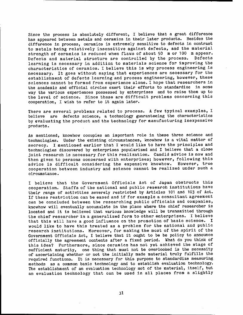
Since the process is absolutely different, I believe that a great difference has appeared between metals and ceramics in their later products. Besides the difference in process, ceramics is extremely sensitive to defects in contrast to metals being relatively insensitive against defects, and the material strength of ceramics is reduced when flaws of about 50 m or 100 m appear. Defects and material structure are controlled by the process. Defects learning is necessary in addition to materials science for improving the characteristics of ceramics. I believe this is why process engineering is necessary. It goes without saying that experiences are necessary for the establishment of defects learning and process engineering, however, these sciences cannot be formed from experience alone. I hope that researchers in the academic and official circles exert their efforts to standardize in some way the various experiences possessed by enterprises and to raise them up to the level of science. Since these are difficult problems concerning this cooperation, I wish to refer to it again later.
There are several problems related to process. A few typical examples, I believe are defects science, a technology guaranteeing the characteristics by evaluating the product and the technology for manufacturing inexpensive products.
As mentioned, knowhow occupies an important role in these three science and technologies. Under the existing circumstances, knowhow is a vital matter of secrecy. I mentioned earlier that I would like to have the principles and technologies discovered by enterprises popularized and I believe that a close joint research is necessary for this realization. Candid advice is now and then given to persons concerned with enterprises; however, following this advice is difficult considering the expensive knowhow. However, true cooperation between industry and science cannot be realized under such a circumstance.
I believe that the Government Officials Act of Japan obstructs this cooperation. Staffs of the national and public research institutions have their range of activities severely restricted by Articles 101 and 103 of Act. If these restriction can be eased and if for example a consultant agreement can be concluded between the researching public officials and companies, knowhow will eventually accumulate in the place where the chief researcher is located and it is believed that various knowledge will be transmitted through the chief researcher in a generalized form to other enterprises. I believe that this will have a good influence on the promotion of basic science. I would like to have this treated as a problem for the national and public research institutions. Moreover, for making the most of the spirit of the Government Officials Act, I believe that it ought to be be policy to announce officially the agreement contents after a fixed period. What do you think of this idea? Furthermore, since ceramics has not yet achieved the stage of sufficient maturity, one thing that must not be overlooked is the necessity of ascertaining whether or not the initially made material truly fulfills the required functions. It is necessary for this purpose to standardize measuring methods as a common basic technology and to establish evaluation technology. The establishment of an evaluation technology not of the material, itself, but an evaluation technology that can be used in all places from a slightly
31
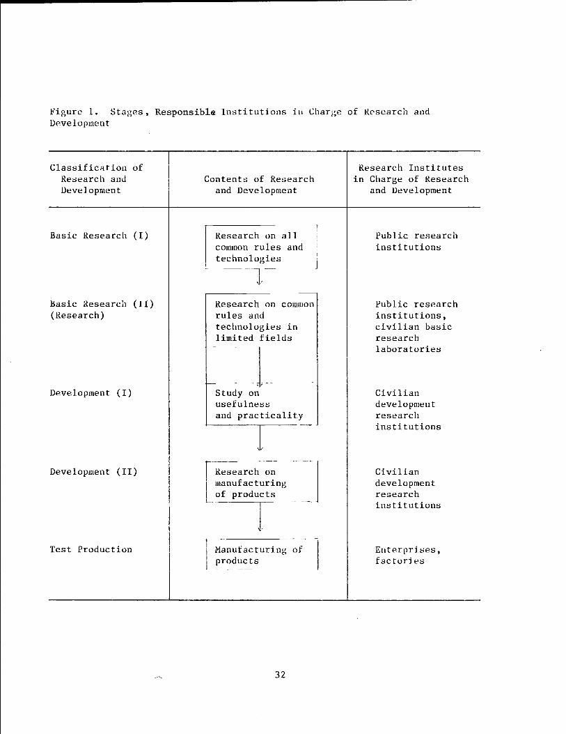
Figure 1. Stages, Responsible Institutions in Charge of Research and Development
Classification of Research and Development
Contents of Research and Development
Research Institutes in Charge of Research
and Development
Basic Research (I) Research common r technolo
on all ules and gies
Public research institutions
J Basic Research (11) (Research)
Development (I)
Research rules an technolo limited
Study on usefulne and prac
on common d gies in fields
ss ticality
Public research institutions, civilian basic research laboratories
Civilian development research
v /
institutions
Development (II) Research on manufacturing of products
Civilian development research
\
institutions
Test Production Manufacturing of products
Enterprises, factories
32
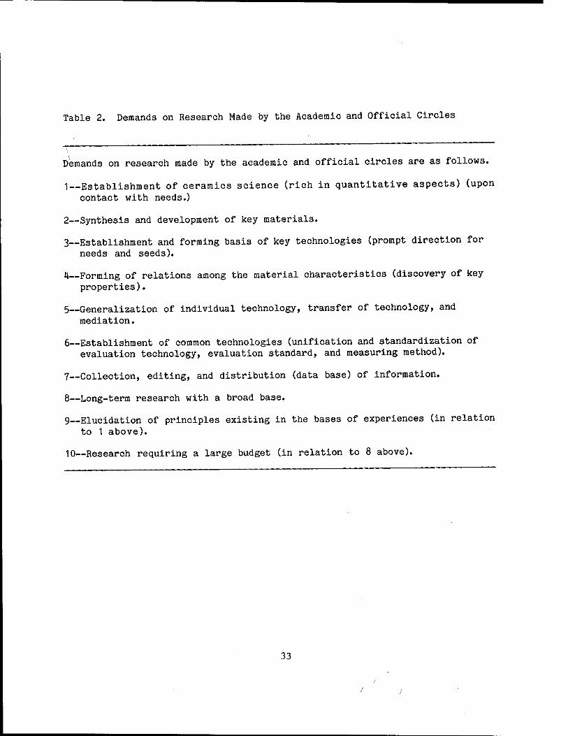
Table 2. Demands on Research Made by the Academic and Official Circles
Demands on research made by the academic and official circles are as follows.
1—Establishment of ceramics science (rich in quantitative aspects) (upon contact with needs.)
2—Synthesis and development of key materials.
3--Establishment and forming basis of key technologies (prompt direction for needs and seeds).
H—Forming of relations among the material characteristics (discovery of key properties).
5--Generalization of individual technology, transfer of technology, and mediation.
6—Establishment of common technologies (unification and standardization of evaluation technology, evaluation standard, and measuring method).
7—Collection, editing, and distribution (data base) of information.
8—Long-term research with a broad base.
9~Elucidation of principles existing in the bases of experiences (in relation to 1 above).
10—Research requiring a large budget (in relation to 8 above).
33
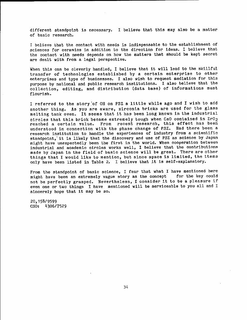
different standpoint is necessary. I believe that this may also be a matter of basic research.
I believe that the contact with needs is indispensable to the establishment of sciences for ceramics in addition to the direction for ideas. I believe that the contact with needs depends on how the matters that should be kept secret are dealt with from a legal perspective.
When this can be cleverly handled, I believe that it will lead to the skillful transfer of technologies established by a certain enterprise to other enterprises and type of businesses. I also wish to request mediation for this purpose by national and public research institutions. I also believe that the collection, editing, and distribution (data base) of informations must flourish.
I referred to the story'of OH on PSZ a little while ago and I wish to add another thing. As you are aware, zirconia bricks are used for the glass melting tank oven. It seems that it has been long known in the industrial circles that this brick became extremely tough when CaO contained in ZrC>2 reached a certain value. From recent research, this effect has been understood in connection with the phase change of PSZ. Had there been a research institution to handle the experiences of industry from a scientific standpoint,' it is likely that the discovery and use of PSZ as science by Japan might have unexpectedly been the first in the world. When cooperation between industrial and academic circles works well, I believe that the contributions made by Japan in the field of basic science will be great. There are other things that I would like to mention, but since space is limited, the items only have been listed in Table 2. I believe that it is self-explanatory.
From the standpoint of basic science, I fear that what I have mentioned here might have been an extremely vague story as the concept for the key could not be perfectly grasped. Nevertheless, I consider it to be a pleasure if even one or two things I have mentioned will be serviceable to you all and I sincerely hope that it may be so.
20,158/9599 CSO: 4306/7529
34
ADVANCED MATERIALS
DEVELOPMENT OF ORGANIC PHOTOMEMORIES DISCUSSED
Tokyo KINO ZAIRYO in Japanese Sep 86 pp 41-51
[Article by Kazuyuki Horie, assistant professor, Faculty of Technology, Tokyo University; first paragraph is editorial introduction]
[Text] The development of photomemory materials using organic molecules is newly attracting attention because of the expectation for ultrahigh density photomemories and an increasing demand for erasable DRAW (direct read after write) type recording media capable of repeating writing and erasing opera- tions. This report consolidates the results of study on the mechanism that accounts for photochromism and photochemical hole burning which are the principles of photon mode photomemory materials and the method of their eval- uation made from the viewpoint of solid-state chemistry and physics.
1. Introduction
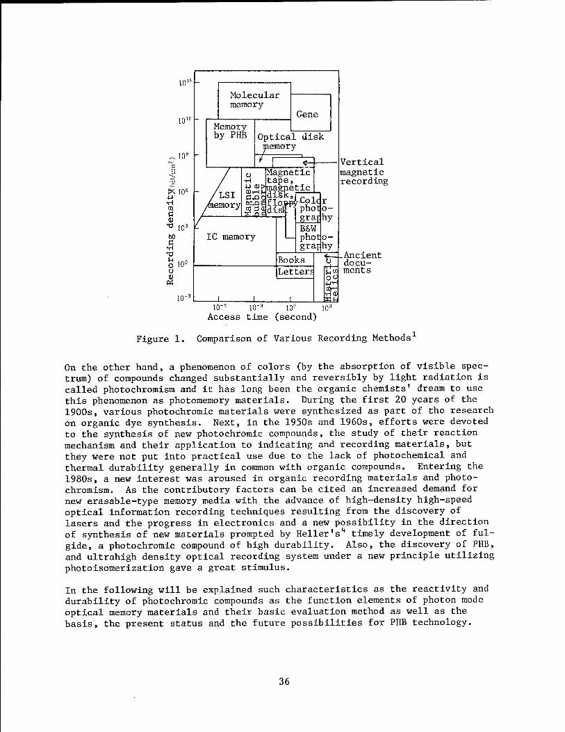
Materials are objectively existing substances with a new added value of some technological usefulness and are classified according to their properties, the types of raw materials, functions or uses. Recording (memory) materials are a classification made with attention paid to their functions and include magnetic, optical, semiconductor, and organic molecular memories. The rela- tionship between recording density of various memories and their access time is as shown in Figure l.1 The upper limit of packing density of magnetic disks most widely used at present is 108 bits/cm2, and in order to realize an an ultrahigh density recording by far exceeding this limit and matching that of molecular memory, the appearance of new principles (properties) has been hoped for. Further, the recording systems, too, have developed from a ROM (read only memory) type that only reproduces the data recorded beforehand, to a DRAW (direct read after write) type capable of reproducing after recording, and then to an Erasable DRAW or a RAM (random access memory) type capable of erasing and writing. The term memory material usually means "erasable" and what has been noted from this viewpoint is photochemical hole burning (PHB) ' using amorphous organic molecules as raw materials and based on spectroscopy and photochemistry. The PHB not only offers a new possibility to materialize ultrahigh density recording but also provides a new probing method to clarify amorphous materials in the low-temperature solid phase from the micro stand- point.
35
Memory by PHB
Molecular memory
Gene
Optical disk memory
■gggjdist
Magnetic •H tape, •y^>magnetic ,
IC memory
Books
r photjo- grajhy B&W phono- graphy
Letter;
j_
tr-
io-6 1(T3 10° Access time (second)
T+- 5_. CO
COH ■HO)
Vertical magnetic recording
Ancient docu- ments
io3
Figure 1. Comparison of Various Recording Methods1
On the other hand, a phenomenon of colors (by the absorption of visible spec- trum) of compounds changed substantially and reversibly by light radiation is called photochromism and it has long been the organic chemists' dream to use this phenomenon as photomemory materials. During the first 20 years of the 1900s, various photochromic materials were synthesized as part of the research on organic dye synthesis. Next, in the 1950s and 1960s, efforts were devoted to the synthesis of new photochromic compounds, the study of their reaction mechanism and their application to indicating and recording materials, but they were not put into practical use due to the lack of photochemical and thermal durability generally in common with organic compounds. Entering the 1980s, a new interest was aroused in organic recording materials and photo- chromism. As the contributory factors can be cited an increased demand for new erasable-type memory media with the advance of high-density high-speed optical information recording techniques resulting from the discovery of lasers and the progress in electronics and a new possibility in the direction of synthesis of new materials prompted by Heller's4 timely development of ful- gide, a photochromic compound of high durability. Also, the discovery of PHB, and ultrahigh density optical recording system under a new principle utilizing photoisomerization gave a great stimulus.
In the following will be explained such characteristics as the reactivity and durability of photochromic compounds as the function elements of photon mode optical memory materials and their basic evaluation method as well as the basis, the present status and the future possibilities for PHB technology.
36
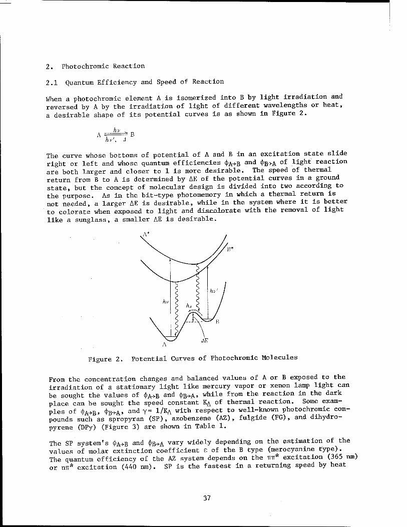
2. Photochromic Reaction
2.1 Quantum Efficiency and Speed of Reaction
When a photochromic element A is isomerized into B by light irradiation and reversed by A by the irradiation of light of different wavelengths or heat, a desirable shape of its potential curves is as shown in Figure 2.
hu', J
The curve whose bottoms of potential of A and B in an excitation state slide right or left and whose quantum efficiencies CJ^B and (J>B->A
of light reaction are both larger and closer to 1 is more desirable. The speed of thermal return from B to A is determined by AE of the potential curves in a ground state, but the concept of molecular design is divided into two according to the purpose. As in the bit-type photomemory in which a thermal return is not needed, a larger AE is desirable, while in the system where it is better to colorate when exposed to light and discolorate with the removal of light like a sunglass, a smaller AE is desirable.
Figure 2. Potential Curves of Photochromic Molecules
From the concentration changes and balanced values of A or B exposed to the irradiation of a stationary light like mercury vapor or xenon lamp light can be sought the values of C|)A>B and tj>B->A> while from the reaction in the dark place can be sought the speed constant % of thermal reaction. Some exam- ples of <j>A+B, <fe+At and Y= 1/*A with respect to well-known photochromic com- pounds such as spropyran (SP), azobenzene (AZ), fulgide (FG), and dihydro- pyrene (DPy) (Figure 3) are shown in Table 1.
The SP system's <j)A>B and <J>B->A varY widely depending on the estimation of the
values of molar extinction coefficient e of the B type (merocyanine type). The quantum efficiency of the AZ system depends on the TIT* excitation (365 nm) or n-rr* excitation (440 nm) . SP is the fastest in a returning speed by heat
37
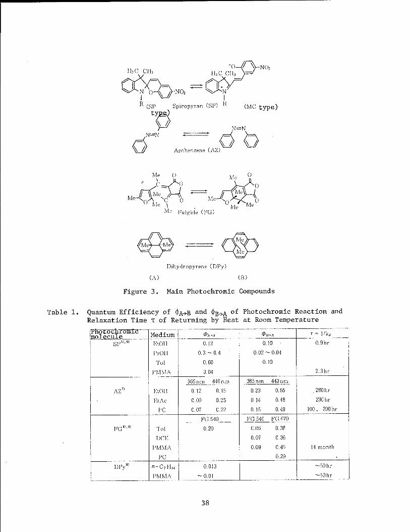
R (SP Spiropyran (SP) R (VIC type)
^ // N=N
> // Azobonzene (AZ)
N=N
w /> \J
MeA„A -c o Me Fulsnde (KG)
Dihydropyrene (DPy)
(A) (B)
Figure 3. Main Photochromic Compounds
Table 1. Quantum Efficiency of <|>A-»B anc* 4>B->A °^ Relaxation Time T of Returning by Heat
Photochromic Reaction and at Room Temperature
Photochromic molecule Medium ©A-B 0B-A r= 1/kj
SP5)'6' Eton 0.12 0.10 0.9hr
PrOH 0.3-0.4 0.02-0.04
Tol 0.60 0.10
PMMA 0.04 2.3hr
365 n in 440 nm 365 n in 440 nm
AZ7' EtOlI 0.12 0.15 0.23 0.55 280hr
Et Ac 0.09 0.25 0.14 0.48 230 hr
PC 0.07 0.22 0.15 0.49 100, 200 hr
KG4,,8, Tol
FÜ 540 KG 540 KG 670
0.06 0.38 0.20
DCE 0.07 0.36
PMMA 0.09 0.45 14 month
PC 0.29 • DPy9) n-C7Hi4 0.013 -50 hr
PMMA -0.01 ~50hr
38

and the time required for its color to die away completely in solutions was 45 seconds in toluene (Tol) , 2 minutes in dichloroethane (DCE) , 24 minutes in acetonitrile, and over 2 hours in ethanol. The time T required for the concentration of AZ to become l/e is about 10 days and its activation energy is 18 kcal/mol. Thermal decoloring of FG is very slow and does not actually take place in PMMA at room temperature. As for DPy,9 a stable dihydropyrene type (A) shows a more distinct color. As for spiropyran, too, the MC type in the colored state has been noted to show a thermally stable reverse photo- chromism.10
2.2 Matrix Effect on the Progress of Reaction
Until now, the reactivity and quantum efficiency of photochromic molecules have mainly been examined in solutions. But since they are actually used in the solidphase as a polymer matrix, it is necessary to clarify the matrix effect by examining how the reactivity changes in the solid phase where the freedom of molecular movement is restricted. »
The solid-phase reaction passes the following three stages as temperatures change from high to low:
1) Progress of reaction at the same speed as in solutions by a chemical reaction rate-determination.
2) Nonuniform progress of reaction reflecting a matrix's molecular movement by a molecular movement rate-determination.
3) The freezing of reaction by the freezing of molecular movements. Criti- cal free volume Ufc necessary to cause photochromic reaction is pretty large in the case of SP, but it is so small in the case of AZ, FG, and DPy that it is less subject to molecular movements of the matrix. In consequence, at temperatures close to room temperature, the return of SP by heat is at the stage mentioned in 2) since it is slower in solid phase below Tg than in solutions, while isomerization of AZ or FG is presumed to be at the stage mentioned in 1) even in solid phase below T„ since it proceeds nearly at the same speed both in solid phase and in solutions. The returning speed by heat of AZ isomerized in film is divided into two components; one higher than and the other the same as the thermal reaction speed in solution. The higher component is given rise to because a portion of "eis" molecules are left in the strained state (hysteresis) in solid phase when isomerized.7 A similar phenomenon of thereturning speed by heat in film becoming higher than in solutions at the initial stage can also be observed in the case of DPy.9
Since photoisomerization reaction occurs in an extremely short excitation life, if there is a critical free volume Ufc of a certain size as in the case of thephotodecoloration reaction of SP from the MC to the SP type, it is thought that there is a distribution in the free volume Uf around reaction molecules and the only molecules whose surrounding Uf is larger than Ufc react and contribute to <j>B+A« Since the distribution of free volumes is thermally redistributed, the Arrhenius plot of apparent photoisomerization speed coefficients proportionate to <})B^ shows curves reflecting Tg, Tg, and
39
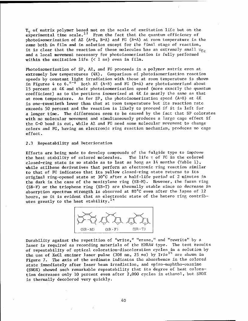
TT of matrix polymer based not on the scale of excitation life but on the experimental time scale.13 From the fact that the quantum efficiency of photoisomerization of AZ (A*B, B*A) and FG (B->A) at room temperature is the same both in film and in solution except for the final stage of reaction, it is clear that the reaction of these molecules has an extremely small Ufc and a local movement necessary for photoisomerization is fully performed within the excitation life (< 1 ns) even in film.
Photoisomerization of SP, AZ, and FG proceeds in a polymer matrix even at extremely low temperatures (4K). Comparison of photoisomerization reaction speeds by constant light irradiation with those at room temperature is shown in Figures 4 to 6.6-8 Both AZ (A->B) and FG (B->A) are photoisomerized about 15 percent at 4K and their photoisomerization speed (more exactly the quantum coefficient) as to the portions isomerized at 4K is nearly the same as that at room temperature. As for SP, the photoisomerization speed (A->B) at 4K is one-twentieth lower than that at room temperature but its reaction rate exceeds 50 percent and the reaction is likely to proceed if it is left for a longer time. The differences seem to be caused by the fact that SP colorates with no molecular movement and simultaneously produces a large cage effect if the C-0 bond is cut, while AZ and FG need some molecular movement to change colors and FG, having an electronic ring reaction mechanism, produces no cage effect.
2.3 Repeatability and Deterioration
Efforts are being made to develop compounds of the fulgide type to improve the heat stability of colored molecules. The life T of FG in the colored closed-ring state is so stable as to last as long as 14 months (Table 1), while stilbene derivatives that perform an electronic ring reaction similar to that of FG indicates that its yellow closed-ring state returns to its original ring-opened state at 30°C after a half-life period of 2 minutes in the dark in the case of the mesitylene ring (SB-M). However, the furan ring (SB-F) or the triophene ring (SB-T) are thermally stable since no decrease in absorption spectrum strength is observed at 80°C even after the lapse of 12 hours, so it is evident that an electronic state of the hetero ring contrib- utes greatly to the heat stability.11*
<*■ ii <£ ̂ <& %1 (SB -M) (SB -F) (SB -T)
Durability against the repetition of "write," "erase," and "rewrite" by a laser is required as recording materials of the EDRAW type. The test results of repeatability of optical coloration-discoloration cycles in a solution by the use of XeCl excimer laser pulse (308 nm, 25 ns) by Irie11* are shown in Figure 7, The axis of the ordinate indicates the absorbence in the colored state immediately after laser beam irradiation, and spiro-naphtho-oxazine (SNOX) showed such remarkable repeatability that its degree of heat colora- tion decreases only 10 percent even after 2,000 cycles in ethanol, but SNOX is thermally decolored very quickly.
40
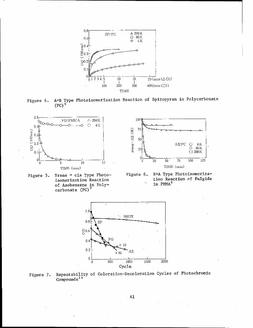
0.6
■0.5 SP/PC A 298 K
O 80 K O 4K
20 (min (AO)) I
400(min(C0)
Figure 4. A+B Type Photoisomerization Reaction of Spiropyran in Polycarbonate
(PC)6
5 10
TIME (min)
Figure 5. Trans ->■ eis Type Photo- isomerization Reaction of Azobenzene in Poly- carbonate (PC)7
1UU'
75 ,-N
N! < 50
i
05 e Ö 25
n
AZ/PC O 4K ! O 40 K [I 288K
Figure 6.
25 50 75 100
TIME (min)
125
B->A Type Photoisomeriza- tion Reaction of Fulgide in PMMA8
- ■=
1.0,
••• SNOX 0.8 -\ SP
g0.6< FA -
0.4' .FG
jX 10 0.2 -
X 10 AZ
0 r i r 500 1000
Cycle 1500 2000
Figure 7. Repeatability of Coloration-Decoloration Cycles of Photochromic
Compounds Xh
41
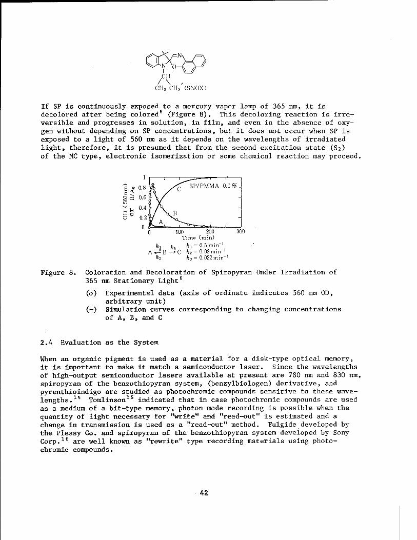
0£C CH
/ \ , CHj CM, (SNC)X)
If SP is continuously exposed to a mercury vapor lamp of 365 nm, it is decolored after being colored6 (Figure 8). This decoloring reaction is irre- versible and progresses in solution, in film, and even in the absence of oxy- gen without depending on SP concentrations, but it does not occur when SP is exposed to a light of 560 nm as it depends on the wavelengths of irradiated light, therefore, it is presumed that from the second excitation state (S2) of the MC type, electronic isomerization or some chemical reaction may proceed.
1
9 = 0.8 c < gm 0.6
~ u °-4
O 0.2
0 0 100 200 300
Time (min) ki fc, &i = O.amin''
A^B->C £2= 0.02min-' kz ft3 = 0.022min-1
Figure 8. Coloration and Decoloration of Spiropyran Under Irradiation of 365 nm Stationary Light6
(o) Experimental data (axis of ordinate indicates 560 nm OD, arbitrary unit)
(-) Simulation curves corresponding to changing concentrations of A, B, and C
k ' 1
SP/PMMA QA96 .
vB -
it A, — 1 "O—l ^—1 1
2.4 Evaluation as the System
When an organic pigment is used as a material for a disk-type optical memory, it is important to make it match a semiconductor laser. Since the wavelengths of high-output semiconductor lasers available at present are 780 nm and 830 nm, spiropyran of the benzothiopyran system, (benzylbiologen) derivative, and pyrenthioindigo are studied as photochromic compounds sensitive to these wave- lengths. lh Tomlinson15 indicated that in case photochromic compounds are used as a medium of a bit-type memory, photon mode recording is possible when the quantity of light necessary for "write" and "read-out" is estimated and a change in transmission is used as a "read-out" method. Fulgide developed by the Plessy Co. and spiropyran of the benzothiopyran system developed by Sony Corp.16 are well known as "rewrite" type recording materials using photo- chromic compounds.
42
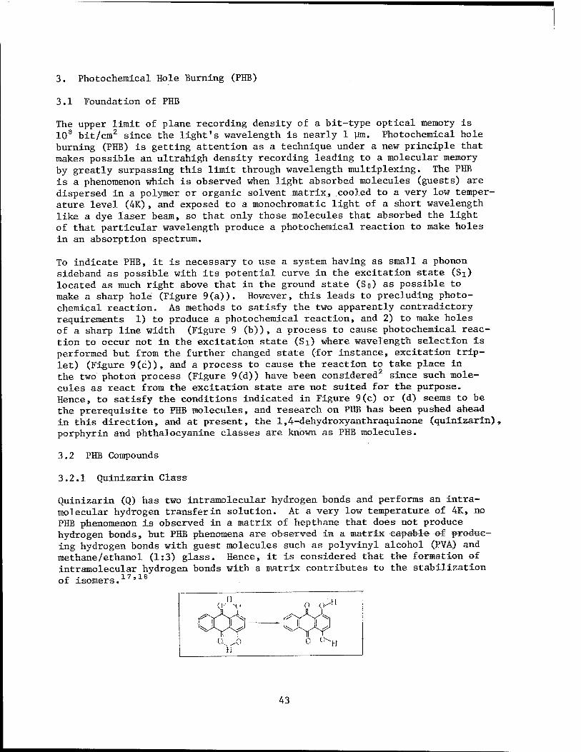
3. Photochemical Hole Burning (PHB)
3.1 Foundation of PHB
The upper limit of plane recording density of a bit-type optical memory is 108 bit/cm2 since the light's wavelength is nearly 1 ym. Photochemical hole burning (PHB) is getting attention as a technique under a new principle that makes possible an ultrahigh density recording leading to a molecular memory by greatly surpassing this limit through wavelength multiplexing. The PHB is a phenomenon which is observed when light absorbed molecules (guests) are dispersed in a polymer or organic solvent matrix, cooled to a very low temper- ature level (4K), and exposed to a monochromatic light of a short wavelength like a dye laser beam, so that only those molecules that absorbed the light of that particular wavelength produce a photochemical reaction to make holes in an absorption spectrum.
To indicate PHB, it is necessary to use a system having as small a phonon sideband as possible with its potential curve in the excitation state (Sx) located as much right above that in the ground state (So) as possible to make a sharp hole (Figure 9(a)). However, this leads to precluding photo- chemical reaction. As methods to satisfy the two apparently contradictory requirements 1) to produce a photochemical reaction, and 2) to make holes of a sharp line width (Figure 9 (b)), a process to cause photochemical reac- tion to occur not in the excitation state (Si) where wavelength selection is performed but from the further changed state (for instance, excitation trip- let) (Figure 9(c)), and a process to cause the reaction to take place in the two photon process (Figure 9(d)) have been considered2 since such mole- cules as react from the excitation state are not suited for the purpose. Hence, to satisfy the conditions indicated in Figure 9(c) or (d) seems to be the prerequisite to PHB molecules, and research on PHB has been pushed ahead in this direction, and at present, the 1,4-dehydroxyanthraquinone (quinizarin), porphyrin and phthalocyanine classes are known as PHB molecules.
3.2 PHB Compounds
3.2.1 Quinizarin Class
Quinizarin (Q) has two intramolecular hydrogen bonds and performs an intra- molecular hydrogen transfer in solution. At a very low temperature of 4K, no PHB phenomenon is observed in a matrix of hepthane that does not produce hydrogen bonds, but PHB phenomena are observed in a matrix capable of produc- ing hydrogen bonds with guest molecules such as polyvinyl alcohol (PVA) and methane/ethanol (1:3) glass. Hence, it is considered that the formation of intramolecular hydrogen bonds with a matrix contributes to the stabilization of isomers.17'18
n o o-}1
f^ FIYS , ^ fS W- \XJ ^ KJ
H 0 o-H
43

V -Q
Figure 9. Models of Photochemical Reactions
The quantum efficiency of hole formation of quinizarin is reported to be about 10~3 to 10"1*,18 but the author and others19 obtained the value of 1 x 10~2 for the Q/PMMA system. The hole width of PHB of quinizarin increases with the rise of temperatures, reflecting the amorphous state of the system.
3.2.2 Porphyrin phthalocyanine Class
Porphyrin containing no metallic atoms stabilizes to either of the two types of tautomers at very low temperatures, and can perform PHB for its absorption.
In the polycrystal matrix of n-alkane, a hole stroke width (uniform width) was AAh a 10-3A against an absorption stroke width (nonuniform width) ä\± i 1 A. Tetrophenyl-porphin (TPP) and phthalocyanine (H2Pc) indicates the PHB even in amorphous PMMA, polystyrene and polyethylene and their absorption and hole stroke widths increase (M± ~ 200 Ä, AXh cr 0.2 Ä) . The porphin ring has a hard structure and is less susceptible to thermal motion of a matrix since the electon system is separated from a lattice and is capable of retaining a hole at temperatures close to a liquid nitrogen temperature. Especially the H2Pc/PMMA system (Figure 10) is cited as one of the promising wavelength multiplex optical memory materials because of its relatively high quantum efficiency of hole formation ranging from 10~2 to 10"3, its high thermosta- bility of holes and its superior optical property at 4K due to a reversible photochemical reaction and its ease of handling because it retains a solid state at room temperature 20 The PHB of H2Pc by a semiconductor laser of 830 nm in concentrated sulfuric acid is also reported. 21
3.2.3 Other Compounds
The color center of ionic crystal of alkali halide also exhibits a PHB. Since it permits a hole formation within the wavelength range (750 - 850 nm) of a semiconductor laser, it is regarded as a promising material from the viewpoint of practical application of PHB memory 22 But, since its absorption
44
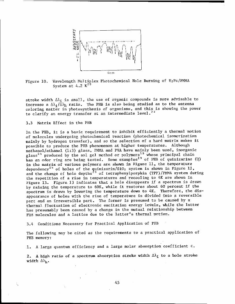
6 rim
Figure 10. Wavelength Multiplex Photochemical Hole Burning of H2PC/PMMA System at 4.2 K 20
stroke width AX-^ is small, the use of organic compounds is more advisable to increase a AX-j_/AXh ratio. The PHB is also being studied as to the antenna coloring matter in photosynthesis of organisms, and this is showing the power to clarify an energy transfer at an intermediate level.
3.3 Matrix Effect in the PHB
In the PHB, it is a basic requirement to inhibit efficiently a thermal motion of molecules undergoing photochemical reaction (photochemical isomerization mainly by hydrogen transfer)» and so the selection of a hard matrix makes it possible to produce the PHB phenomenon at higher temperatures. Although methanol/ethanol (1:3) glass, PMMA and FVA have mainly been used, inorganic glass2 ** produced by the sol gel method or polymers19 whose principal chain has an odor ring are being tested. Some examples19 of PHB of quinizarine (Q) in the matrix of various polymers are shown in Figure 11* the temperature dependency2k of holes of the quinizarin/Si02 system is shown in Figure 12, and the change of hole depths 5 of tetraphenylporphin (TPP)/PMMA system during the repetition of a rise in temperatures and recooling to 4K are shown in Figure 13. Figure 13 indicates that a hole disappears if a spectrum is drawn by raising the temperature to 60K, while it restores about 60 percent if the spectrum is drawn by lowering the temperature down to 4K. Therefore, the dis- appearance of holes with the rise of temperature is divided into a reversible part and an irreversible part. The former is presumed to be caused by a thermal fluctuation of electronic excitation energy levels, while the latter has presumably been caused by a change in the mutual relationship between PHB molecules and a lattice due to the latter*s thermal motion.
3.4 Conditions Necessary for Practical Application of PHB
The following may be cited as the requirements to a practical application of PHB memory:
1. A large quantum efficiency and a large molar absorption coefficient e.
2. A high ratio of a spectrum absorption stroke width AXj to a hole stroke width AXh.
45
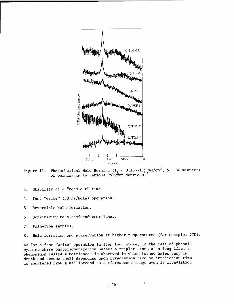
a
Q/PMMA
Q/PVA
"to Sk
Q/PSF 2
^^^w*^ J L
514.Ü 514.6 515.2 !■ (nm)
515.8
Figure 11. Photochemical Hole Burning (I. = 0.15/^1.5 mW/cm2, 5-30 minutes) of Quinizarin in Various Polymer Matrices19
3. Stability at a "read-out" time.
4. Fast "write" (30 ns/hole) operation.
5. Reversible hole formation.
6. Sensitivity to a semiconductor laser.
7. Film-type samples.
8. Hole formation and preservation at higher temperatures (for example, 77K)
As for a fast "write" operation in item four above, in the case of phthalo- cyanine where photoisomerization passes a triplet state of a long life, a phenomenon called a bottleneck is observed in which formed holes vary in depth and become small depending upon irradiation time as irradiation time is shortened from a millisecond to a microsecond range even if irradiation
46
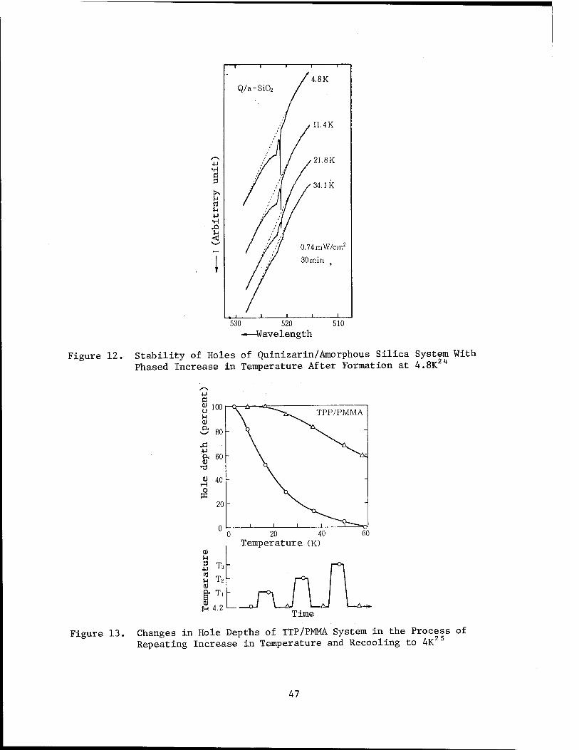
i "T 1 1
/4.8K Q/a -Si02
7 .WAY.
1 /21.8K •rl Ö / /
>•. M rt i-t ■P •H
/ ■'
/ / 34.1 K
7 /
'/ ' / 0.74mW/cm2
i
. i >
30 min t
1 1 1
530 520 ——Wavelength
510
Figure 12. Stability of Holes of Quinizarin/Amorphous Silica System With Phased Increase in Temperature After Formation at 4.8K 2 4
0 20 40 Temperature (K)
60
a) u u tö u
H
T3
T2
T,
4.2 Time
Figure 13. Changes in Hole Depths of TTP/PMMA System in the Process of Repeating Increase in Temperature and Recooling to 4K
47
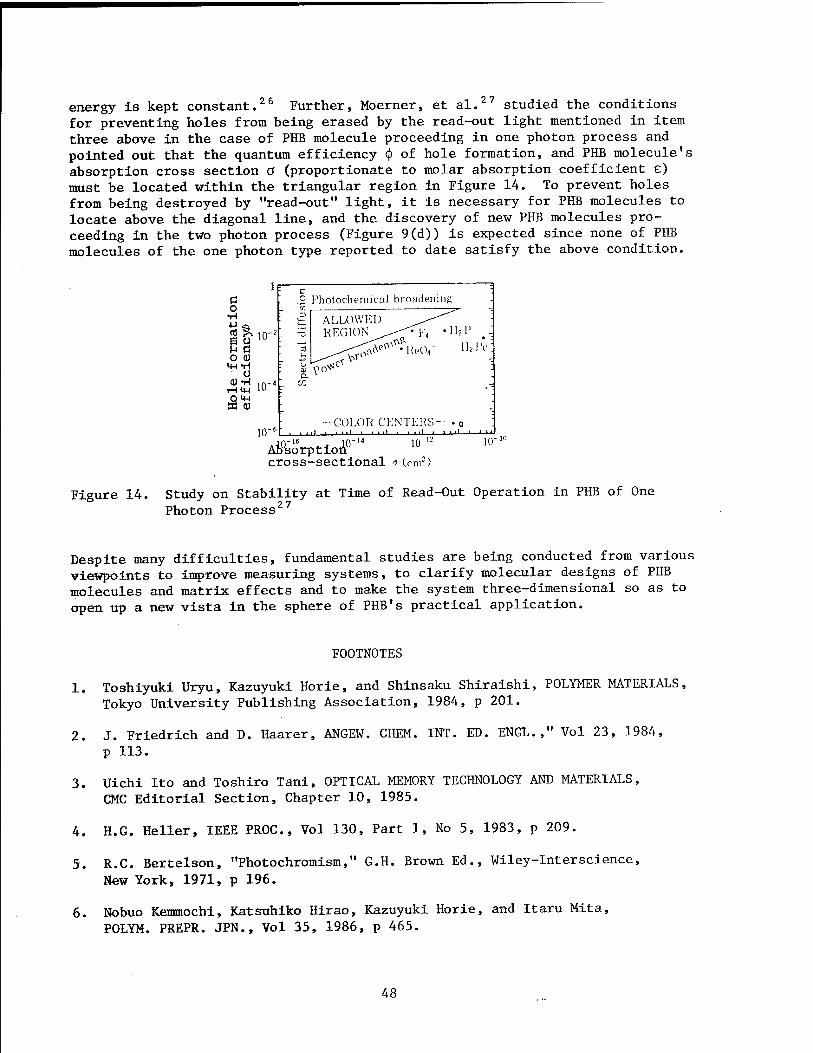
26 energy is kept constant."" Further, Moerner, et al.27 studied the conditions for preventing holes from being erased by the read-out light mentioned in item three above in the case of PHB molecule proceeding in one photon process and pointed out that the quantum efficiency <\> of hole formation, and PHB molecule's absorption cross section a (proportionate to molar absorption coefficient e) must be located within the triangular region in Figure 14. To prevent holes from being destroyed by "read-out" light, it is necessary for PHB molecules to locate above the diagonal line, and the discovery of new PHB molecules pro- ceeding in the two photon process (Figure 9(d)) is expected since none of PHB molecules of the one photon type reported to date satisfy the above condition.
c Photochemical broadening
'"'I
1'
"1
'
"T
' '
"1 '
'
"1
;
S
pect
ral
diff
u ALLOWED ^^"" '■ REGION-^--<F4 *H2P ..
^* ;
-COLOR CENTERS- • o : i , .ni ■ ini .ii.jj._i—__i—i—i_i_
o •H
0 U 10" u n o <u m -H
o <DTI ,n-
om SO Q)
Ati&'rptloA0"4
cross-sectional •■> (cm2)
Figure 14. Study on Stability at Time of Read-Out Operation in PHB of One Photon Process27
Despite many difficulties, fundamental studies are being conducted from various viewpoints to improve measuring systems, to clarify molecular designs of PHB molecules and matrix effects and to make the system three-dimensional so as to open up a new vista in the sphere of PHB's practical application.
FOOTNOTES
1. Toshiyuki Uryu, Kazuyuki Horie, and Shinsaku Shiraishi, POLYMER MATERIALS, Tokyo University Publishing Association, 1984, p 201.
2. J. Friedrich and D. Haarer, ANGEW. CHEM. INT. ED. ENGL.," Vol 23, 1984, p 113.
3. Uichi Ito and Toshiro Tani, OPTICAL MEMORY TECHNOLOGY AND MATERIALS, CMC Editorial Section, Chapter 10, 1985.
4. H.G. Heller, IEEE PROC., Vol 130, Part 1, No 5, 1983, p 209.
5. R.C. Bertelson, "Photochromism," G.H. Brown Ed., Wiley-Interscience,
New York, 1971, p 196.
6. Nobuo Kemmochi, Katsuhiko Hirao, Kazuyuki Horie, and Itaru Mita, POLYM. PREPR. JPN., Vol 35, 1986, p 465.
48
7. Katsuhiko Hirao, Itaru Mita, and Kazuyuki Horle, Ibid., Vol 34, 1985, p 1985.
8. Kazuyuki Hiro and Katsuhlko Hirao, Unpublished ms.
9. Shinichi Murakami, Tetsuo Tsutsui, Shogo Saito, Takehiko Yatnato, and Masashi Tashiro, POLYM. PREPR. JPN., Vol 34, 1985, p 1577.
10. Ismrnt Shimizu, Hiroshi Kokado, and Eiichi Inoue, K0GY0 KAGAKU ZASSHI [INDUSTRIAL CHEMISTRY MAGAZINE], Vol 72, 1969, pp 166, 171.
11. Kazuyuki Horie, FUNCTIONAL MATERIALS, Vol 4 No 10, 1984, p 15.
12. Kazuyuki Horie and Itaru Mita, HIGHPOLYMER, Vol 34, 1985, p 448.
13. K. Horie, M. Tsukamoto, and I. Mita. EUR POLYM. J., Vol 21, 1985, p 805.
14. Masahiro Irie, "Hikari Kiroku Gijutsu to Zairyo," CMC Editorial Section, Chapter 13, 1985.
15. W.J. Tomlinson, APPL. OPTICS, Vol 23, 1984, p 4609.
16. Junetsu Seto, "Hikari Kioku Gijutsu to Zairyo," CMC Editorial Section, Chapter 2, 1985.
17. D.H. Burland and D. Haarer, IBM J. RES. DEVELOP, Vol 23 1979, p 534.
18. F. Graf, H.K. Hong, A. Nazzal, and B. Haarer, CHEM. PHYS. LETT., Vol 59, 1978, p 217.
19. Kazuyuki Horie, Katsuhiko Hirao, and Itaru Mita, POLYM. PREPR. JPN., Vol 35, 1986, p 476.
20. A.R. Gutierrez, J. Friedrich, D. Haarer, and H. Wolfrum., IBM J. RES. DEVELOP, Vol 26, 1982, p 198.
21. H.W.H. Lee, A.L. Huston, M. Gehrtz, and W.E. Woerner, CHEM. PHYS. LETT., Vol 114, 1985, p 491.
22. C. Oritiz, R.M. Macfarland, R.M. Shelby, W. Lenth, and G.C. Bjorklund, APPL. PHYS., Vol 25, 1981, p 87.
23. J. Friedrich. H. Scheer, D. Zickendraht-Wendelstadt, and D. Haarer, J. AMER. CHEM. S0C, Vol 103, 1981, p 1030.
24. T. Tanl, H. Namikawa, K. Aral, and A. Makishimä, J. APPL. PHYS., Vol 58, 1985, p 3559.
25. Toshlhiro Nishi, Koichi Arishima, and Hiroaki Hiratsuka, POLYM. PREPR. JPN., Vol 34, 1985, p 1068.
26. H. Rotnagnoll, W.E. Moerner, F.M. Schellenberg, M.D. Levenson, and G.C. Bjorklund, J. OPT. S0C. AM., Vol B, 1, 1984, p 341.
27. W.E. Moerner and M.D. Levenson, Ibid., Vol B, 2, 1985, p 915.
20152/9365 CSO: 4306/3645
49

AEROSPACE, CIVIL AVIATION
NEW MATERIALS APPLICATIONS TO AIRCRAFT ENGINES DISCUSSED
Tokyo KOKU GIJUTSU in Japanese Jan 87 pp 61-63
[Article by the editor]
[Text] New material technologies have been outlined in a previous article (November 1986 issue). In this article, it is planned to more minutely
1 explain the new materials or the new material (processing) technologies shown iin Table 1. In Figure 1, how these new materials are going to be used in air- craft engines is shown.
Table 1. New Materials/Material Technologies
• New composite materials
(1) Fiber-reinforced plastics FRP (2) Fiber-reinforced metals FRM
• Directional controlled alloys
(1) Directional solidified alloy DS (2) Single crystals SC (3) Directional solidified eutectics alloy DSES
• Powder metallurgy PM
o Oxide dispersion strengthened metals ODS
• Super plastic forming SPF
o Intermetallic compound IMC
e Ceramics Ceram
e Rapid solidification rate process RSR
a Hot isostatic press HIP
/ 9 Diffusion bonding DB
50
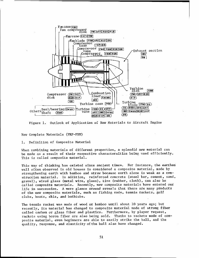
Fan caseITRPI Fan compres^ ^^—^
nFanvane (FRP)[FRM1
Fan blade GO^IIPEIIIEIDDD ' Compressor ^-—p—.
base CFRPXia Compressor |FRP|| FRMirWsRTDB
vane ' .Compressor IFRMIIRSR
Exhaust section llMC|
%=v (PM)(SPF)tRSRj (HTP)
F.RM
Others Shaft Seal /bearing(ceram) Turbine LFRMJ(P~T)(5PS
Vane rSPFl|lMcHCeram| 1WSRT|H I PIT PB
Turbine .—-,,—. blade Ü5M](DS) (SC)|DiESir5DSirSPFl HMC| |CeraintlRSR[| HI p]
Figure 1. Outlook of Application of New Materials to Aircraft Engine
New Complete Materials (FRP-FRM)
1. Definition of Composite Material
When combining materials of different properties, a splendid new material can be made as a result of their respective charactersitics being used efficiently. This is called composite material.
This way of thinking has existed since ancient times. For instance, the earthen wall often observed in old houses is considered a composite material, made by strengthening earth with bamboo and straw because earth alone is weak as a con- struction material. In addition, reinforced concrete (steel bar, cement, sand, gravel), wired glass (metal wire, glass), tire (rubber, cloth), can also be called composite materials. Recently, new composite materials have entered our life in succession. A mere glance around reveals that there are many products of the new composite materials, such as fishing rods, tennis rackets, golf clubs, boats, skis, and bathtubs.
The tennis racket was made of wood or bamboo until about 10 years ago; but recently, its material has changed to composite material made of strong fiber called carbon or glass fiber and plastics. Furthermore, by player request, rackets using boron fiber are also being sold. Thanks to rackets made of com- posite material, even beginners are able to easily strike the ball, and the quality, response, and elasticity of the ball also have changed.
51
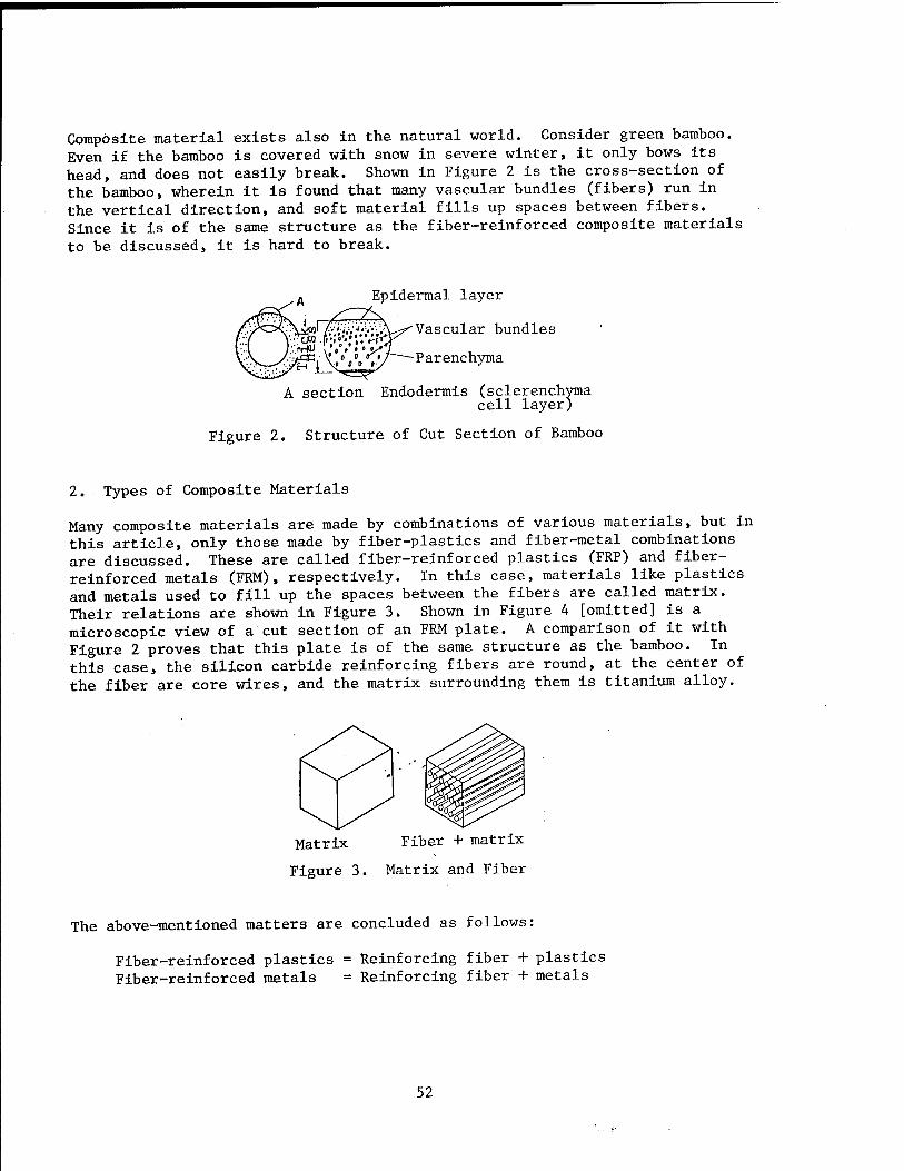
Composite material exists also in the natural world. Consider green bamboo. Even if the bamboo is covered with snow in severe winter, it only bows its head, and does not easily break. Shown in Figure 2 is the cross-section of the bamboo, wherein it is found that many vascular bundles (fibers) run in the vertical direction, and soft material fills up spaces between fibers. Since it is of the same structure as the fiber-reinforced composite materials to be discussed, it is hard to break.
Epidermal layer
Vascular bundles
Parenchyma
A section Endodermis (sclerenchyma cell layer)
Figure 2. Structure of Cut Section of Bamboo
2. Types of Composite Materials
Many composite materials are made by combinations of various materials, but in this article, only those made by fiber-plastics and fiber-metal combinations are discussed. These are called fiber-reinforced plastics (FRP) and fiber- reinforced metals (FRM), respectively. In this case, materials like plastics and metals used to fill up the spaces between the fibers are called matrix. Their relations are shown in Figure 3. Shown in Figure 4 [omitted] is a microscopic view of a cut section of an FRM plate. A comparison of it with Figure 2 proves that this plate is of the same structure as the bamboo. In this case, the silicon carbide reinforcing fibers are round, at the center of the fiber are core wires, and the matrix surrounding them is titanium alloy.
Matrix Fiber + matrix
Figure 3. Matrix and Fiber
The above-mentioned matters are concluded as follows:
Fiber-reinforced plastics = Reinforcing fiber + plastics Fiber-reinforced metals = Reinforcing fiber + metals
52

3. Reinforcing Fiber and Matrix
(1) Reinforcing Fiber
Typical reinforcing fibers used in FRP and FRM are shown below.
The development of new reinforcing fibers is also in progress.
» Metal materials—Iron, tungsten ® Inorganic materials—Carbon» silicon carbide, alumina, glass e Organic materials—Aromatic group, heat-resisting nylon s Composite fibers—Boron/tungsten
Silicon carbide/tungsten Silicon carbide/carbon
One of the characteristics of composite materials is the property of being light and strong, and as shown in Table 2, they are smaller in specific gravity and stronger in power than conventional metal materials. The secret of composite materials being strong is because the reinforcing fiber can withstand strong forces. Consequently, for increasing the strength of com- posite materials, it would be logical to increase the amount of fiber and decrease the amount of matrix, but even in this, there is a limit; it is con- sidered that their ratio should be about 60-40, although it varies with the combination of fiber and matrix.
Table 2. Examples of Comparison of Specific Gravity and Tensile Strength Between Reinforcing Fiber and Metal Material
Fiber Specific gravity
Tensile strength kg/mm
Carbon 1.8 250-350
Boron 2.6 350
Silicon carbide 3.0 350
Aluminum alloy 2.7 32
Stainless steel 7.9 50
Titanium alloy 4.4 110
(2) Matrix
Materials used as matrix are shown below:
e FRP—Unsaturated polyester, epoxy, polyaside thermoplastic, and other resins, s FRM—Aluminum, magnesium, lead, copper, nickel, titanium, and their alloys.
53
4. Manufacturing Method
Various manufacturing methods are being developed according to the shapes and uses of the products. It is enough to put reinforcing fibers in the required parts and directions (strength is largest in the fiber direction), and fill up the spaces between them with the matrix materials. There are more than 15 manufacturing methods for FRP and more than seven for FRM, and their improve- ments are being pushed. In Figure 5 [omitted], a manufacturing method called the hot press method is shown as an example of manufacturing FRM.
5. Advantages and Disadvantages
FRP has many advantages such as being light and strong, good in formability, and not easily corroded. In addition, it has the characteristic of being pervious to electric wave; thus, the aircraft made of FRP is not easily detected by radar. On the other hand, it has the disadvantage of being susceptible to shock. For example, there was a bitter experience at a certain firm that was pushing devel- opment of FRP for the fan blade of the jet engine; it was found that when suck- ing in a bird or ice while in flight the fan blade would break from the shock, and the development program was greatly obstructed. Furthermore, the tempera- tures at which it can be used are also low: 250°C or below.
FRM also is light and strong, and although the specific gravity is the same as metal materials, a highly heat-resistant FRM also can be acquired. In addition, it has the advantage of being good in shock resistance, but because of poor productivity, various molding methods are being developed.
In both FRP and FRM, their strength is determined according to the amount of fibers contained therein. In FRM made of silicon carbide fibers and aluminum alloy (fiber content 48 percent), a tensile strength of 175 kg/mm2 can be obtained, and as its specific gravity is low at 2.8, it is seen that this mate- rial is more advantageous when compared with the conventional alloys shown in Table 2. In FRP made of carbon fibers and epoxy resin (fiber content 60 per- cent) , a tensile strength of 150 kg/mm2 or above has been acquired (specific gravity 1.6).
6. Uses
There are not yet many instances of using FRM and FRP as aircraft engine mate- rials. It can be said they are in the development stage. Actual uses of FRP for fan vanes, compressor case, and nose cone have been reported. Furthermore, for the future, its application to stationary parts such as fan case, compres- sor vane, and turbine case is being considered. On the other hand, FRM is under development for its practical use for shafts. In addition to its promis- ing uses, application to fan vane and blade, compressor vane and blade, and rotating parts is being considered, and using it for turbine disk, vane, and blade is also being studied.
It is expected that application of both FRP and FRM to aircraft engines will reach full stride from now on. These are now serving for weight reduction pur- poses in the aircraft fuselage of the F-15, the F-14, and the B-lB. The range
54

of their application is considered to be wide, including space equipment, artificial satellites, rockets, missiles, automobiles, robots, and medical equipment, as well as common daily necessities.
Note: Since tensile strength and specific gravity mentioned in the text vary according to makers and manufacturing conditions, please take them as refer- ence values. All these data are those acquired at room temperature.
20150/9365 CSO: 4306/2482
55

AEROSPACE, CIVIL AVIATION
NATIONAL AEROSPACE LABORATORY NEWS—DECEMBER 1986
ATP Propeller Analysis
Tokyo KOGIKEN NYUSU in Japanese Dec 86 pp 1-3
[Article by Shigeru Saito, 2d Aerodynamics Division]
[Text] Analysis of ATP Propeller by Three-Dimensional Euler Equation
The ATP aircraft, which is going to appear in the 1990's, is a trans- sonic aircraft driven by an 8- to 12-blade propeller, which will cruise at Mach 0.75 to 0.8. Its outstanding characteristic is that, in comparison with existing turbofan engines, a rise of propulsion efficiency of more than 30 percent can be obtained in the overall efficiency. To make the most of this characteristic, various design features have been incorporated into the ATP blades. First, it can be cited that they are thin blades, they have a large twist angle, the number of blades is large and the diameter is small, and that they have sweepforward and sweepback angle. These characteristics have been determined by noise, structural, and aerodynamic, etc., considerations.
ATP propellers can be roughly divided into two types: single rotating (SR) and counter rotating (CR). In addition, according to the place where the propeller is installed, it is further divided into two types: tractor type and pusher type; and thus a total of four combinations of them can be con- sidered. The analysis of ATP blades for this sort of form has steadily advanced in step with recent improvements in numerical computation tech- nology.
At this laboratory, too, an ATP research institution was organized, and its aerodynamics research group (Environmental Pollution Group: Hiroshi Kobayashi, 2d Aerodynamics Division: Shigeru Saito) has continued the development of computer code to estimate the aerodynamic performance of the ATP propeller. This group is primarily directed toward writing computer code for the tractor-type SR and CR propellers. As for computation technique, the local circulation method based on the potential theory and the three-dimensional moving blade numerical scheme using the Euler equation are under considera- tion. Up to now, the code for the SR propeller using the local circulation method has been completed, and that for CR, too, is nearing completion and is scheduled to be unveiled before long. By this theory however the cascade
56
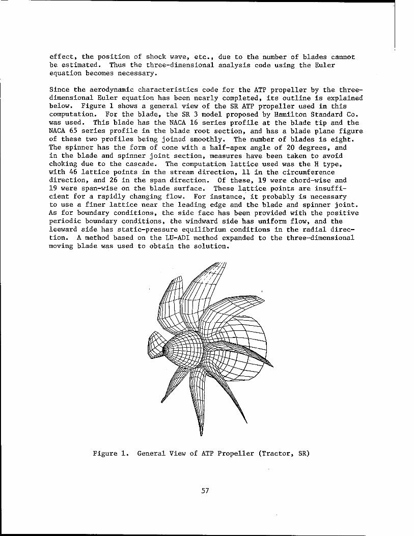
effect, the position of shock wave, etc., due to the number of blades cannot be estimated. Thus the three-dimensional analysis code using the Euler equation becomes necessary.
Since the aerodynamic characteristics code for the ATP propeller by the three- dimensional Euler equation has been nearly completed, its outline is explained below. Figure 1 shows a general view of the SR ATP propeller used in this computation. For the blade, the SR 3 model proposed by Hamilton Standard Co. was used. This blade has the NACA 16 series profile at the blade tip and the NACA 65 series profile in the blade root section, and has a blade plane figure of these two profiles being joined smoothly. The number of blades is eight. The spinner has the form of cone with a half-apex angle of 20 degrees, and in the blade and spinner joint section, measures have been taken to avoid choking due to the cascade. The computation lattice used was the H type, with 46 lattice points in the stream direction, 11 in the circumference direction, and 26 in the span direction. Of these, 19 were chord-wise and 19 were span-wise on the blade surface. These lattice points are insuffi- cient for a rapidly changing flow. For instance, it probably is necessary to use a finer lattice near the leading edge and the blade and spinner joint. As for boundary conditions, the side face has been provided with the positive periodic boundary conditions, the windward side has uniform flow, and the leeward side has static-pressure equilibrium conditions in the radial direc- tion. A method based on the LU-ADI method expanded to the three-dimensional moving blade was used to obtain the solution.
Figure 1. General View of ATP Propeller (Tractor, SR)
57
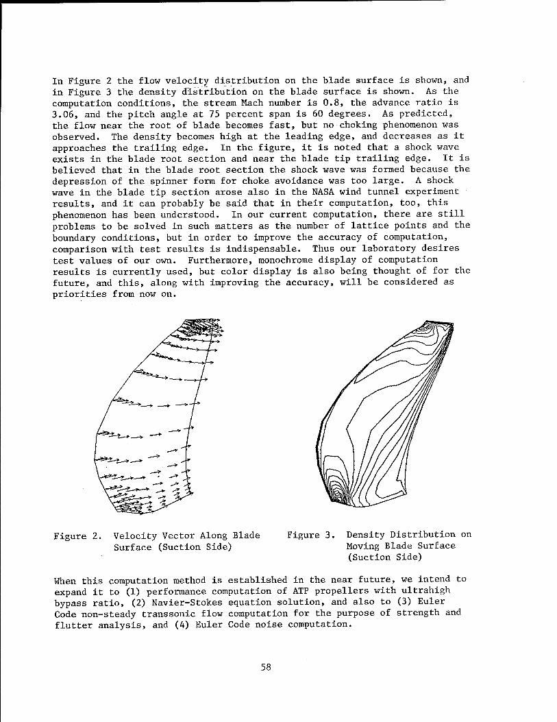
In Figure 2 the flow velocity distribution on the blade surface is shown, and in Figure 3 the density distribution on the blade surface is shown. As the computation conditions, the stream Mach number is 0.8, the advance ratio is 3.06, and the pitch angle at 75 percent span is 60 degrees. As predicted, the flow near the root of blade becomes fast, but no choking phenomenon was observed. The density becomes high at the leading edge, and decreases as it approaches the trailing edge. In the figure, it is noted that a shock wave exists in the blade root section and near the blade tip trailing edge. It is believed that in the blade root section the shock wave was formed because the depression of the spinner form for choke avoidance was too large. A shock wave in the blade tip section arose also in the NASA wind tunnel experiment results, and it can probably be said that in their computation, too, this phenomenon has been understood. In our current computation, there are still problems to be solved in such matters as the number of lattice points and the boundary conditions, but in order to improve the accuracy of computation, comparison with test results is indispensable. Thus our laboratory desires test values of our own. Furthermore, monochrome display of computation results is currently used, but color display is also being thought of for the future, and this, along with improving the accuracy, will be considered as priorities from now on.
Figure 2. Velocity Vector Along Blade Figure 3. Surface (Suction Side)
Density Distribution on Moving Blade Surface (Suction Side)
When this computation method is established in the near future, we intend to expand it to (1) performance computation of ATP propellers with ultrahigh bypass ratio, (2) Navier-Stokes equation solution, and also to (3) Euler Code non-steady transsonic flow computation for the purpose of strength and flutter analysis, and (4) Euler Code noise computation.
58
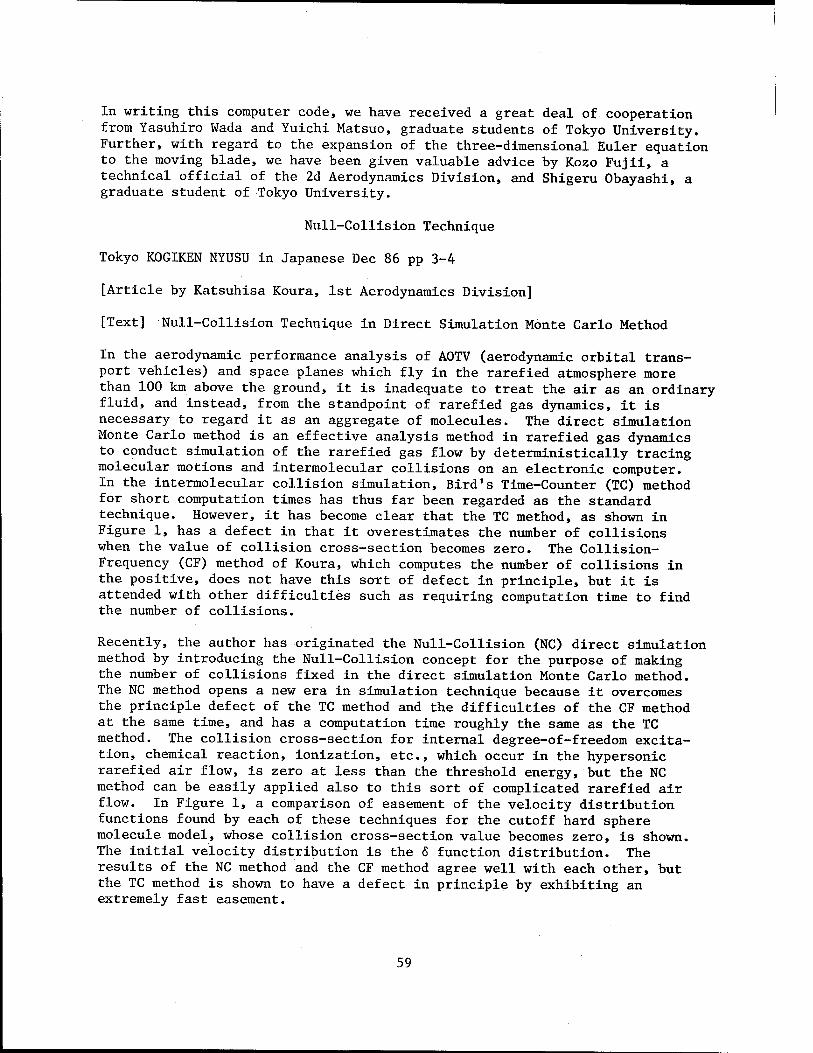
In writing this computer code, we have received a great deal of cooperation from Yasuhiro Wada and Yuichi Matsuo, graduate students of Tokyo University. Further, with regard to the expansion of the three-dimensional Euler equation to the moving blade, we have been given valuable advice by Kozo Fujii, a technical official of the 2d Aerodynamics Division, and Shigeru Obayashi, a graduate student of Tokyo University.
Null-Collision Technique
Tokyo K0G1KEN NYUSU in Japanese Dec 86 pp 3-4
[Article by Katsuhisa Koura, 1st Aerodynamics Division]
[Text] Null-Collision Technique in Direct Simulation Monte Carlo Method
In the aerodynamic performance analysis of AOTV (aerodynamic orbital trans- port vehicles) and space planes which fly in the rarefied atmosphere more than 100 km above the ground, it is inadequate to treat the air as an ordinary fluid, and instead, from the standpoint of rarefied gas dynamics, it is necessary to regard it as an aggregate of molecules. The direct simulation Monte Carlo method is an effective analysis method in rarefied gas dynamics to conduct simulation of the rarefied gas flow by deterministically tracing molecular motions and intermolecular collisions on an electronic computer. In the intermolecular collision simulation, Bird's Time-Counter (TC) method for short computation times has thus far been regarded as the standard technique. However, it has become clear that the TC method, as shown in Figure 1, has a defect in that it overestimates the number of collisions when the value of collision cross-section becomes zero. The Collision- Frequency (CF) method of Koura, which computes the number of collisions in the positive, does not have this sort of defect in principle, but it is attended with other difficulties such as requiring computation time to find the number of collisions.
Recently, the author has originated the Null-Collision (NC) direct simulation method by introducing the Null-Collision concept for the purpose of making the number of collisions fixed in the direct simulation Monte Carlo method. The NC method opens a new era in simulation technique because it overcomes the principle defect of the TC method and the difficulties of the CF method at the same time, and has a computation time roughly the same as the TC method. The collision cross-section for internal degree-of-freedom excita- tion, chemical reaction, ionization, etc., which occur in the hypersonic rarefied air flow, is zero at less than the threshold energy, but the NC method can be easily applied also to this sort of complicated rarefied air flow. In Figure 1, a comparison of easement of the velocity distribution functions found by each of these techniques for the cutoff hard sphere molecule model, whose collision cross-section value becomes zero, is shown. The initial velocity distribution is the 6 function distribution. The results of the NC method and the CF method agree well with each other, but the TC method is shown to have a defect in principle by exhibiting an extremely fast easement.
59
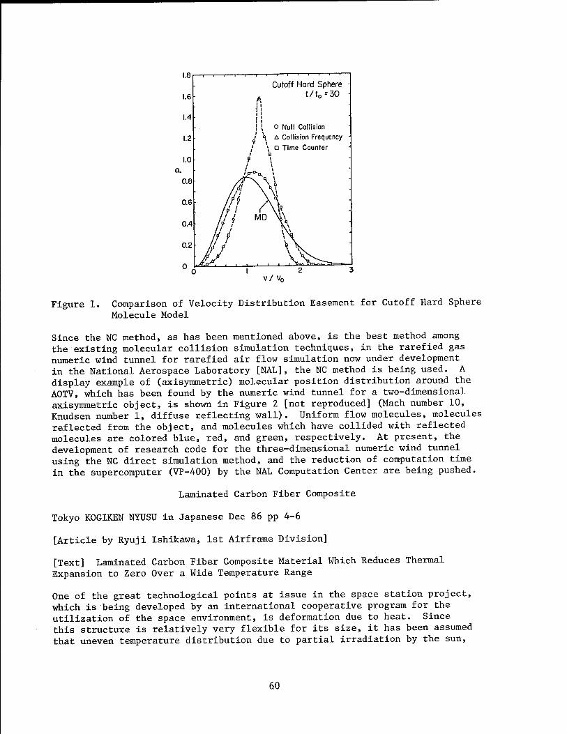
1.8
1.6
1.4
1.2
1.0 L
0.8
0.6
0.4
0.2
Cutoff Hard Sphere t/t0=30
o Null Collision A Collision Frequency a Time Counter
Figure 1.
v/ v0
Comparison of Velocity Distribution Easement for Cutoff Hard Sphere Molecule Model
Since the NC method, as has been mentioned above, is the best method among the existing molecular collision simulation techniques, in the rarefied gas numeric wind tunnel for rarefied air flow simulation now under development in the National Aerospace Laboratory [NAL], the NC method is being used. A display example of (axisymmetric) molecular position distribution around the AOTV, which has been found by the numeric wind tunnel for a two-dimensional axisymmetric object, is shown in Figure 2 [not reproduced] (Mach number 10, Knudsen number 1, diffuse reflecting wall). Uniform flow molecules, molecules reflected from the object, and molecules which have collided with reflected molecules are colored blue, red, and green, respectively. At present, the development of research code for the three-dimensional numeric wind tunnel using the NC direct simulation method, and the reduction of computation time in the supercomputer (VP-400) by the NAL Computation Center are being pushed.
Laminated Carbon Fiber Composite
Tokyo K0GIKEN NYUSU in Japanese Dec 86 pp 4-6
[Article by Ryuji Ishikawa, 1st Airframe Division]
[Text] Laminated Carbon Fiber Composite Material Which Reduces Thermal Expansion to Zero Over a Wide Temperature Range
One of the great technological points at issue in the space station project, which is being developed by an international cooperative program for the utilization of the space environment, is deformation due to heat. Since this structure is relatively very flexible for its size, it has been assumed that uneven temperature distribution due to partial irradiation by the sun,
60
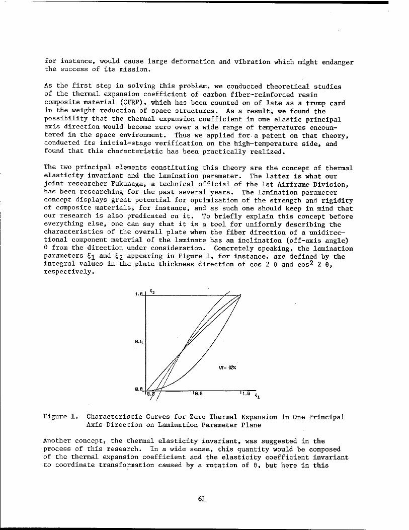
for instance, would cause large deformation and vibration which might endanger the success of its mission.
As the first step in solving this problem, we conducted theoretical studies of the thermal expansion coefficient of carbon fiber-reinforced resin composite material (CFRP), which has been counted on of late as a trump card in the weight reduction of space structures. As a result, we found the possibility that the thermal expansion coefficient in one elastic principal axis direction would become zero over a wide range of temperatures encoun- tered in the space environment. Thus we applied for a patent on that theory, conducted its initial-stage verification on the high-temperature side, and found that this characteristic has been practically realized.
The two principal elements constituting this theory are the concept of thermal elasticity invariant and the lamination parameter. The latter is what our joint researcher Fukunaga, a technical official of the 1st Airframe Division, has been researching for the past several years. The lamination parameter concept displays great potential for optimization of the strength and rigidity of composite materials, for instance, and as such one should keep in mind that our research is also predicated on it. To briefly explain this concept before everything else, one can say that it is a tool for uniformly describing the characteristics of the overall plate when the fiber direction of a unidirec- tional component material of the laminate has an inclination (off-axis angle) 9 from the direction under consideration. Concretely speaking, the lamination parameters £,]_ and g2 appearing in Figure 1, for instance, are defined by the integral values in the plate thickness direction of cos 2 9 and cos2 2 0, respectively.
i.e.
0.5.
0.0
Figure 1. Characteristic Curves for Zero Thermal Expansion in One Principal Axis Direction on Lamination Parameter Plane
Another concept, the thermal elasticity invariant, was suggested in the process of this research. In a wide sense, this quantity would be composed of the thermal expansion coefficient and the elasticity coefficient invariant to coordinate transformation caused by a rotation of 0, but here in this
61
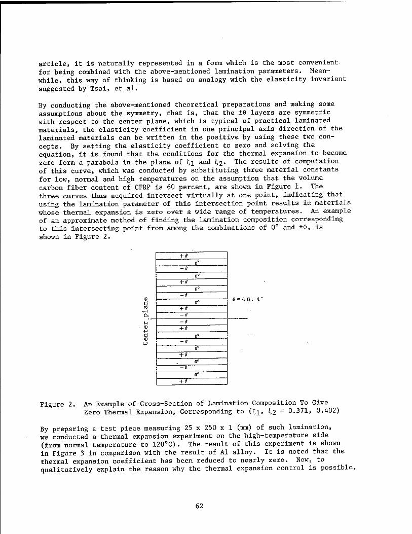
article, it is naturally represented in a form which is the most convenient for being combined with the above-mentioned lamination parameters. Mean- while, this way of thinking is based on analogy with the elasticity invariant suggested by Tsai, et al.
By conducting the above-mentioned theoretical preparations and making some assumptions about the symmetry, that is, that the ±6 layers are symmetric with respect to the center plane, which is typical of practical laminated materials, the elasticity coefficient in one principal axis direction of the laminated materials can be written in the positive by using these two con- cepts. By setting the elasticity coefficient to zero and solving the equation, it is found that the conditions for the thermal expansion to become zero form a parabola in the plane of £1 and £2• The results of computation of this curve, which was conducted by substituting three material constants for low, normal and high temperatures on the assumption that the volume carbon fiber content of CFRP is 60 percent, are shown in Figure 1. The three curves thus acquired intersect virtually at one point, indicating that using the lamination parameter of this intersection point results in materials whose thermal expansion is zero over a wide range of temperatures. An example of an approximate method of finding the lamination composition corresponding to this intersecting point from among the combinations of 0° and ±9, is shown in Figure 2.
+ 0 0°
-e 0°
+ 0 0°
a) -6
e = 4e 0°
cd + 0 Pu -0
U -e 0) + 6 c n° a) 0 -6
0°
+ 0 0°
-0
n° + 6
Figure 2. An Example of Cross-Section of Lamination Composition To Give Zero Thermal Expansion, Corresponding to (£]_, £2 = 0.371, 0.402)
By preparing a test piece measuring 25 x 250 x 1 (mm) of such lamination, we conducted a thermal expansion experiment on the high-temperature side (from normal temperature to 120°C). The result of this experiment is shown in Figure 3 in comparison with the result of Al alloy. It is noted that the thermal expansion Coefficient has been reduced to nearly zero. Now, to qualitatively explain the reason why the thermal expansion control is possible,
62
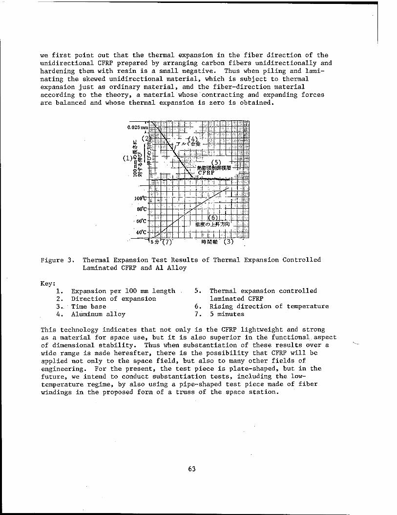
we first point out that the thermal expansion in the fiber direction of the unidirectional CFRP prepared by arranging carbon fibers unidirectionally and hardening them with resin is a small negative. Thus when piling and lami- nating the skewed unidirectional material, which is subject to thermal expansion just as ordinary material, and the fiber-direction material according to the theory, a material whose contracting and expanding forces are balanced and whose thermal expansion is zero is obtained.
0.025 m T» —i i—
rv '& £ in i rirr : .-.:: a- o r." g
il K^ ;;•; •a. -T ML '_;:: ":• 10 -- \
::r:
«K«. ... (DSt \r -" ;= ;H"T
e£ : t—r
wmmnm TTRP
:!' ÜL or '\ r "...
-:■
S«t ~i. '
-.= 1 v.r\ n :l : : i >
- ! 1 1 XT Ü;" 100°C-
ii i: ::;:
V y/l i
0 ... 1 1 6 • 60 C" hktD±.&?3 ft
/ y ID L
5 » T 0 $ W* ( 3 )
Figure 3. Thermal Expansion Test Results of Thermal Expansion Controlled Laminated CFRP and Al Alloy
Key: 1. Expansion per 100 mm length 2. Direction of expansion 3. Time base 4. Aluminum alloy
6. 7.
Thermal expansion controlled laminated CFRP Rising direction of temperature 5 minutes
This technology indicates that not only is the CFRP lightweight and strong as a material for space use, but it is also superior in the functional aspect of dimensional stability. Thus when substantiation of these results over a wide range is made hereafter, there is the possibility that CFRP will be applied not only to the space field, but also to many other fields of engineering. For the present, the test piece is plate-shaped, but in the future, we intend to conduct substantiation tests, including the low- temperature regime, by also using a pipe-shaped test piece made of fiber windings in the proposed form of a truss of the space station.
63
Flutter Control Experiment
Tokyo KOGIKEN NYUSU in Japanese Dec 86 pp 6-8
[Article by ACT Research Institution]
[Text] Second Flutter Control Experiment of High Aspect-Ratio Wing, Active Control Technology (ACT) Research
The ACT research institution of this laboratory conducted a second flutter control experiment this year following the successful flutter control experi- ment of last year, and repeated their achievement of record increase in flutter speed by jointly using two flaps, one on the leading edge and one on the trailing edge. This time, in addition, digital flutter control also was tried.
In the first flutter control experiment last year, we succeeded in releasing the control system at a speed exceeding the original flutter speed and holding back the flutter which was about to occur by restarting the control system, thereby achieving a 9.7 percent increase in the flutter speed by leading-edge flap control. In the current experiment, we have mainly aimed at partially improving the test wing analysis model to become the basis for designing the equations of control and at the same time, verifying the con- trol equations found by the optimal control design method (LQG + degree lowering), increasing the speed more than 10 percent by simultaneously controlling the leading-edge flap and the trailing-edge flap, and trying the digital control, etc., which was not fully tested in the previous experiment.
In the digital control, we manufactured a prototype controller that realizes a control cycle of 500 us by incorporating integer operation in a 32-bit CPU. Figure 1 [not reproduced] shows a series of photographs printed from a 16-mm film which were taken as flutter occurred after an increase in speed of 5.2 percent by digital control of the two flaps on the leading and trailing edges. The photographs clearly catch the state of the controlled wing exhibiting a typical bent and twisted.flutter. As compared to the original flutter speed of 34.8 m/s, flutter occurred at 36.6 m/s in this case.
We have synthesized the control equations by the LQG method on the basis of the analytical model of the wing as in the case of the previous experiment. In the previous experiment, the analytically expected increase (due to con- trol) of the flutter speed was not fully realized, but our study of the test results has proven that there is room for improvement in the analytical model with respect to the characteristics of torsion that have effect on the flutter. Thus we have improved this point, and based on it, we have restated the control equations. By the LQG method, a control equation with high- degree observers of the same degree as the analytical model can be found, and the frequency band of that equation widened to include high-frequency components which were generally omitted in the analytical mode. This wide- band trait of the control equation causes self-excited vibration (spillover) by coupling with the omitted high-degree vibration mode components. To avoid this phenomenon, and simultaneously to make it easier to work with, it is
64
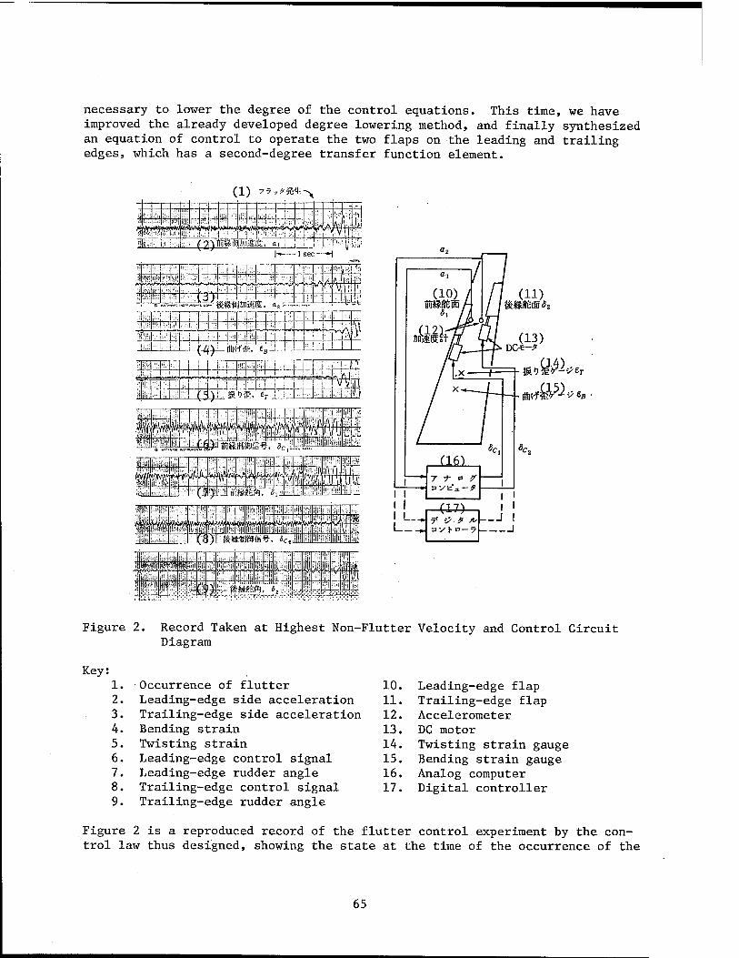
necessary to lower the degree of the control equations. This time, we have improved the already developed degree lowering method, and finally synthesized an equation of control to operate the two flaps on the leading and trailing edges, which has a second-degree transfer function element.
( 1 ) 7 7„#&4l > 1
M 1* w-
rl i
)M S
1 ■ •,•'1 i 1 .. mi... .. *->y«* W^3*^J«w^ >^vOrt^V» A/V4 .l.-j
■ '■ . i (2;)ii:iH(B;jiiäifü;, a,: ; i -l-i-4 p:* h 1 sec —H
ITf rTf ,
:TT JZ ■ I i ; Vi *T" LJ j ; !■ 4_| li ! :rrm r
r_LJ (^ mkiii. ««-!. I -h. !r ■ I-.:. j -i-4—1 ■ i r i _].._ .ui
!■■ I i ' ' . _L, L hJ>:
*.-',■ i ~' ! J IT I l' ; jTfOT "h. I-*
Al m<)k. £r :. i j ■ M : ■■■I.-IFI
ilii " WiV'OiWA'*» tm rS)Tlfe)äM»<ag. °c2
te^wA^VfT'iv
fil .■".< :'/ ;,J: '■ii '' 1 .i " 1; , V:! :|ii ■ i;: !i;: ■I-! ;k "'-. 'ij* w j"] M ÜU- Ui T!( ■ ;,!; illl V' !f ffl Oh ;>'■■ ■ir ill1 1"' ;.;> 1 ; i !'' Tlji : "! ;{■ :■■;:
it! !i'l V: »I ?!!'!
■•i
f;;"i ')< <"i £ $& £1?! ä ''; ))■ v.» -~;*:-:t. -K-^-,-^4- x- /.['. -■:4 Ä rr*:
Figure 2. Record Taken at Highest Non-Flutter Velocity and Control Circuit Diagram
Key: 1. Occurrence of flutter 2. Leading-edge side acceleration 3. Trailing-edge side acceleration 4. Bending strain 5. Twisting strain 6. Leading-edge control signal 7. Leading-edge rudder angle 8. Trailing-edge control signal 9. Trailing-edge rudder angle
10. Leading-edge flap 11. Trailing-edge flap 12. Accelerometer 13. DC motor 14. Twisting strain gauge 15. Bending strain gauge 16. Analog computer 17. Digital controller
Figure 2 is a reproduced record of the flutter control experiment by the con- trol law thus designed, showing the state at the time of the occurrence of the
65
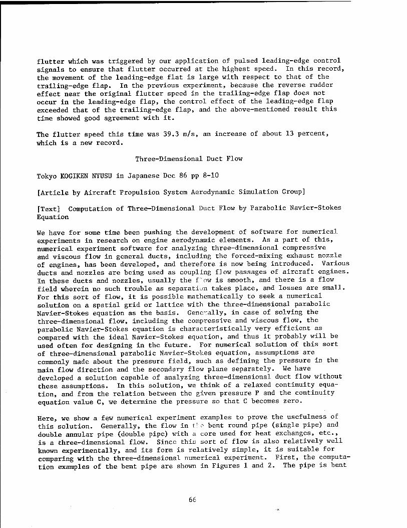
flutter which was triggered by our application of pulsed leading-edge control signals to ensure that flutter occurred at the highest speed. In this record, the movement of the leading-edge flat is large with respect to that of the trailing-edge flap. In the previous experiment, because the reverse rudder effect near the original flutter speed in the trailing-edge flap does not occur in the leading-edge flap, the control effect of the leading-edge flap exceeded that of the trailing-edge flap, and the above-mentioned result this time showed good agreement with it.
The flutter speed this time was 39.3 m/s, an increase of about 13 percent, which is a new record.
Three-Dimensional Duct Flow
Tokyo KOGIKEN NYUSU in Japanese Dec 86 pp 8-10
[Article by Aircraft Propulsion System Aerodynamic Simulation Group]
[Text] Computation of Three-Dimensional Duct Flow by Parabolic Navier-Stokes Equation
We have for some time been pushing the development of software for numerical experiments in research on engine aerodynamic elements. As a part of this, numerical experiment software for analyzing three-dimensional compressive and viscous flow in general ducts, including the forced-mixing exhaust nozzle of engines, has been developed, and therefore is now being introduced. Various ducts and nozzles are being used as coupling flow passages of aircraft engines. In these ducts and nozzles, usually the f ow is smooth, and there is a flow field wherein no such trouble as separation takes place, and losses are small. For this sort of flow, it is possible mathematically to seek a numerical solution on a spatial grid or lattice with the three-dimensional parabolic Navier-Stokes equation as the basis. Gene-ally, in case of solving the three-dimensional flow, including the compressive and viscous flow, the parabolic Navier-Stokes equation is characteristically very efficient as compared with the ideal Navier-Stokes equation, and thus it probably will be used often for designing in the future. For numerical solution of this sort of three-dimensional parabolic Navier-Stokes equation, assumptions are commonly made about the pressure field, such as defining the pressure in the main flow direction and the secondary flow plane separately. We have developed a solution capable of analyzing three-dimensional duct flow without these assumptions. In this solution, we think of a relaxed continuity equa- tion, and from the relation between the given pressure P and the continuity equation value C, we determine the pressure so that C becomes zero.
Here, we show a few numerical experiment examples to prove the usefulness of this solution. Generally, the flow in the bent round pipe (single pipe) and double annular pipe (double pipe) with a core used for heat exchanges, etc., is a three-dimensional flow. Since this sort of flow is also relatively well known experimentally, and its form is relatively simple, it is suitable for comparing with the three-dimensional numerical experiment. First, the computa- tion examples of the bent pipe are shown in Figures 1 and 2. The pipe is bent
66
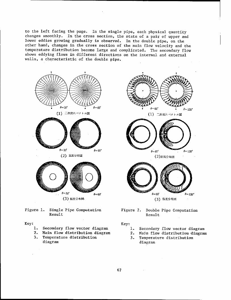
to the left facing the page. In the single pipe, each physical quantity changes smoothly. In the cross section, the state of a pair of upper and lower eddies growing gradually is observed. In the double pipe, on the other hand, changes in the cross section of the main flow velocity and the temperature distribution become large and complicated. The secondary flow shows eddying flows in different directions on the internal and external walls, a characteristic of the double pipe.
0=30°
(1) "ifcfcft.--^ \-A,%
0=60°
0=3CT
(2) 2Mft*m 0=60°
=30"
(3) u&ftmm «=ffi
0=60° • 0=120°
(1) -ftmx-t-? \->m
0=60° 0=120°
0=60°
(3) &%.ft*cM 0=120°
Figure 1. Single Pipe Computation Result
Figure 2. Double Pipe Computation Result
Key: 1. Secondary flow vector diagram 2. Hain flow distribution diagram 3. Temperature distribution
diagram
Key: 1* Secondary flow vector diagram 2. Main flow distribution diagram 3. Temperature distribution
diagram
67
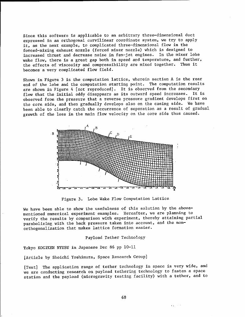
Since this software is applicable to an arbitrary three-dimensional duct expressed in an orthogonal curvilinear coordinate system, we try to apply it, as the next example, to complicated three-dimensional flow in the forced-mixing exhaust nozzle (forced mixer nozzle) which is designed to increased thrust and decrease noise in fan-jet engines. In the mixer lobe wake flow, there is a great gap both in speed and temperature, and further, the effects of viscosity and compressibility are mixed together. Thus it becomes a very complicated flow field.
Shown in Figure 3 is the computation lattice, wherein section A is the rear end of the lobe and the computation starting point. The computation results are shown in Figure 4 [not reproduced]. It is observed from the secondary flow that the initial eddy disappears as its outward speed increases. It is observed from the pressure that a reverse pressure gradient develops first on the core side, and then gradually develops also on the casing side. We have been able to clearly catch the occurrence of separation as a result of gradual growth of the loss in the main flow velocity on the core side thus caused.
Figure 3. Lobe Wake Flow Computation Lattice
We have been able to show the usefulness of this solution by the above- mentioned numerical experiment examples. Hereafter, we are planning to verify the results by comparison with experiment, thereby attaining partial parabolizing with the back pressure taken into account, and the non- orthogonalization that makes lattice formation easier.
Payload Tether Technology
Tokyo KOGIKEN NYUSU in Japanese Dec 86 pp 10-11
[Article by Shoichi Yoshimura, Space Research Group]
[Text] The application range of tether technology in space is very wide, and we are conducting research on payload tethering technology to fasten a space station and the payload (microgravity testing facility) with a tether, and to
68
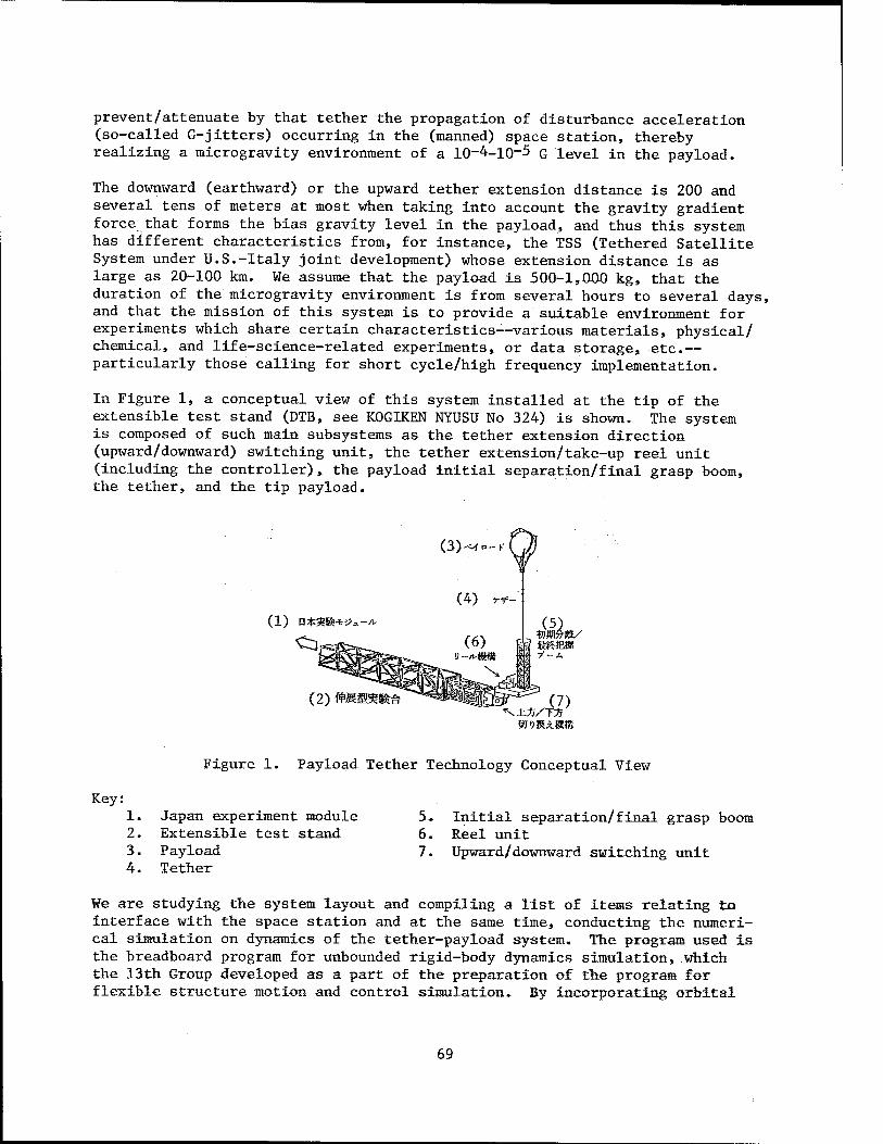
prevent/attenuate by that tether the propagation of disturbance acceleration (so-called G-jitters) occurring in the (manned) space station, thereby realizing a microgravity environment of a 10-4-10-5 G level in the payload.
The downward (earthward) or the upward tether extension distance is 200 and several tens of meters at most when taking into account the gravity gradient force that forms the bias gravity level in the payload, and thus this system has different characteristics from, for instance, the TSS (Tethered Satellite System under U.S.-Italy joint development) whose extension distance is as large as 20-100 km. We assume that the payload is 500-1,000 kg, that the duration of the microgravity environment is from several hours to several days, and that the mission of this system is to provide a suitable environment for experiments which share certain characteristics—various materials, physical/ chemical, and life-science-related experiments, or data storage, etc.— particularly those calling for short cycle/high frequency implementation.
In Figure 1, a conceptual view of this system installed at the tip of the extensible test stand (DTB, see K0GIKEN NYUSU No 324) is shown. The system is composed of such main subsystems as the tether extension direction (upward/downward) switching unit, the tether extension/take-up reel unit (including the controller), the payload initial separation/final grasp boom, the tether, and the tip payload.
(1) a*8t*v>.-*
(2) WMWim- (7)
Figure 1. Payload Tether Technology Conceptual View
Key; 1. Japan experiment module 5. 2. Extensible test stand 6. 3. Payload 7. 4. Tether
Initial separation/final grasp boom Reel unit Upward/downward switching unit
We are studying the system layout and compiling a list of items relating to interface with the space station and at the same time, conducting the numeri- cal simulation on dynamics of the tether-payload system. The program used is the breadboard program for unbounded rigid-body dynamics simulation, which the 13th Group developed as a part of the preparation of the program for flexible structure motion and control simulation» By incorporating orbital
69

motion in this, we have used two rigid-body models with the space station (50 tons) and the tip payload (1 ton) on a circular orbit at an altitude of 500 km as point masses and the tether as a long (massless) hinge composed of a spring and dashpot. As a computation example, the system's behavior (no control) and G-level with a slack tether and nominal length of the hinge of 100 meters are shown in Figure 2. After the slack, collision does not come at once, but the tether stretches a little at first, and repeats it there- after. The absolute quantity of slack tends to gradually increase. The G-level clearly shows a phenomenon of decreasing down to 10~H h 0 in the state of slack tether and returning to 10~4 when the tether stretches.
no
102
1U
I V 94
(2)
78
(4) ,, 00m)
rv A /
\ A 1
V A V / /
40 120
(1)0-2-(a) ff-(f/i>)SS
160 200 xlO"
40
(5)
80 120 (3>*ra s
2 -(b) Wi u-Ou
160 200 xlO"
Figure 2. System's Behavior in Case of Slack Tether
Key: 1.
2. 3.
Figure 2(a). Tether (hinge) length Tether length Time
4. Nominal length 5. Figure 2(b). Gravity level 6. Gravity level
From September to October this year, we conducted a questionnaire on the microgravity environment mission jointly with the Payload Boomerang Tech- nology Group (see KOGIKEN NYUSU No 329) . Hereafter, we plan to promote the clarification of the system concept by referring to the results of this survey and at the same time, to do further simulation, including increased precision and control, of the dynamic models and even down to technical studies of subsystems.
20150/6091 CSO: 4306/2486
70
BIOTECHNOLOGY
PROBLEMS IN APPLICATION OF BIOTECHNOLOGY TO WASTEWATER TREATMENT
Tokyo BIOINDUSTRY in Japanese Dec 86 pp 5-14
[Text] A breakthrough by applying new biotechnology is expected in waste- water treatment. Is it really possible? Basic science must be prepared as the background for the application of new technology. The present waste- water treatment in which filth is dumped directly into water should be reconsidered.
1. Introduction
Excessive expectations of biotechnology in recent years have given us an illusion that some revolutionary changes would happen in areas of technology which support modern civilized society. In wastewater treatment, where bio- technology has been traditionally applied, rapid progress is expected by applying new biotechnology including gene manipulation. In fact,as will be stated later in this report, national projects for this purpose are now under- way.
As we can see recently in electronic industries, the progress of some technol- ogy is beyond our imagination. However, serious analysis shows that rapid progress is supported by an accumulation of studies on basic science and tech- nology. Regarding the biotechnology of wastewater treatment, science and technology as a background for rapid progress has not been prepared. In this report, some new biotechnology problems associated with wastewater treatment are discussed.
2. Efficiency Supported by Cheap Energy Cost
2.1 The Historical Background of Wastewater Treatment
Our excrements have been decomposed under the ground and used effectively as a fertilizer to produce farm products. With the progress of civilization, cities and farm villages have been separated, and the excretion of urban residents has been conveyed to rivers through drainage, where it was diluted and purified. The subsequent expansion of urban areas has led to the corrup- tion of rivers, and at that time the drainage purification had been taken into account.
71
The initial method was practiced around 1860 in Paris and London; it was a process in which sewage irrigated farmlands were decomposed by microorganisms under the grounu. This method required a vast plottage, and was substituted by the trickling filter method, in which purification took place in solid facilities. The use of this facility, which is formed by piling up of macadams up to 1 m high, reduced the required plottage to one-hundredth to treat the same amount of wastewater.
Then, an activated sludge process was developed. This was a method where microorganisms decomposing organic substances were suspended at a high level in wastewater, which was aerated to supply oxygen. This reduced the required plottage further to less than one-tenth. This activated sludge process, which has been in practice since 1920, is a widely used biological wastewater
treatment facility.
2.2 Biological Wastewater Treatment Facility Efficiency
Nowadays, wastewater containing biologically degradable organic substances is treated biologically, except when it is particularly concentrated. Chemical or physical treatment including absorption, chemical oxidation, coagulation, and precipitation are sometimes applied as prior- or post-processes of biologi- cal treatment. However, they cannot be used solely as a major process because it is inferior to the biological method in its efficiency from an economic
point of view.
In biological wastewater treatment, it is essential to supply oxygen to advance the activity of microorganisms for effective decomposition of organic sub- stances. In the trickling filter method, wastewater is carried on the top of the filter and dispersed from there, which makes easier the contact between wastewater and oxygen in the air. In the activated-sludge process, the air from a blower is blown into the bottom of the tank to promote oxygen-supply when the liquid is deep. In the facilities for biological wastewater treatment, oxygen supplied to activate microorganisms consumes a large amount of energy, the energy cost takes a large part of the wastewater treatment budget as the price of energy sources has risen recently.
In biological wastewater treatment facilities, BOD treated by unit power con- sumption for oxygen supply is called "power efficiency." This value varies with various conditions, including operational conditions of the facilitxes, BOD for water to be treated, the concentration of influxed wastewater, BOD load to the facilities, aid the change of these conditions. If the required BOD for water to be treated is taken as 20 mg/£, and urban sewage with BOD of 150 mg/£ is to be treated under the standard condition in each facility, the values of "power efficiency" in different biological wastewater treatment facilities against BOD treated per plottage unit of each facility are shown
in Figure 1.
As stated above, the technology for wastewater treatment has progressed aiming at the development of more efficient facilities; the efficiency in this case is to raise the amount of BOD treated per unit area of a facility. However, with the progress in efficiency, as it is shown in Figure 1, the power required
72
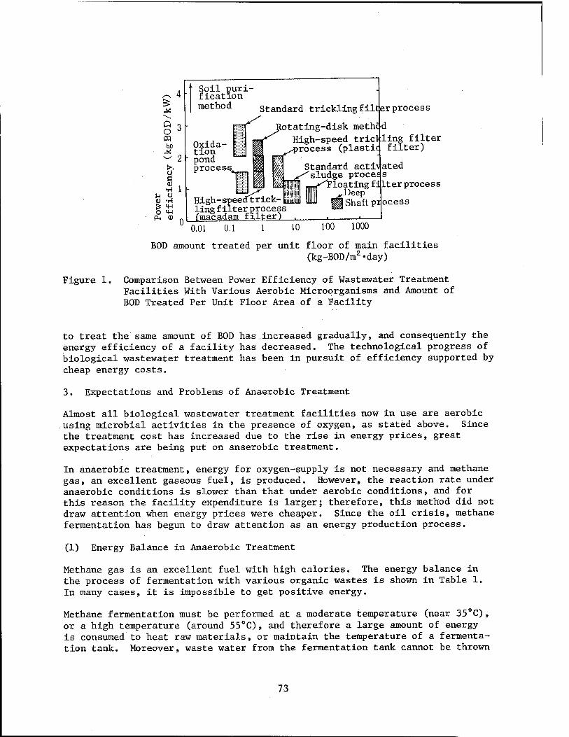
Q O « be
o ■8 •A O
•H iw in
<U
Soil puri- fication method Standard trickling filt er process
Oxida- tion pond proces-s
jtotating-disk methc
1 ^process (plastic) filter)
W\
W& lliijj!
High-speedtrick- iiiiiiiiiii iing filter process (macadam filter)
Standard acti\ated ''sludge proces s r Floating fijlter process
^Deep Shaft pi ocess
0.01 0.1 1 10 100 1000
Figure 1.
BOD amount treated per unit floor of main facilities (kg-B0D/m2«day)
Comparison Between Power Efficiency of Wastewater Treatment Facilities With Various Aerobic Microorganisms and Amount of BOD Treated Per Unit Floor Area of a Facility
to treat the same amount of BOD has .increased gradually, and consequently the energy efficiency of a facility has decreased. The technological progress of biological wastewater treatment has been in pursuit of efficiency supported by cheap energy costs.
3. Expectations and Problems of Anaerobic Treatment
Almost all biological wastewater treatment facilities now in use are aerobic using microbial activities in the presence of oxygen, as stated above. Since the treatment cost has increased due to the rise in energy prices, great expectations are being put on anaerobic treatment.
In anaerobic treatment, energy for oxygen-supply is not necessary and methane gas, an excellent gaseous fuel, is produced. However, the reaction rate under anaerobic conditions is slower than that under aerobic conditions, and for this reason the facility expenditure is larger; therefore, this method did not draw attention when energy prices were cheaper. Since the oil crisis, methane fermentation has begun to draw attention as an energy production process.
(1) Energy Balance in Anaerobic Treatment
Methane gas is an excellent fuel with high calories. The energy balance in the process of fermentation with various organic wastes is shown in Table 1. In many cases, it is impossible to get positive energy.
Methane fermentation must be performed at a moderate temperature (near 35°C) , or a high temperature (around 55°C) , and therefore a large amount of energy is consumed to heat raw materials, or maintain the temperature of a fermenta- tion tank. Moreover, waste water from the fermentation tank cannot be thrown
73
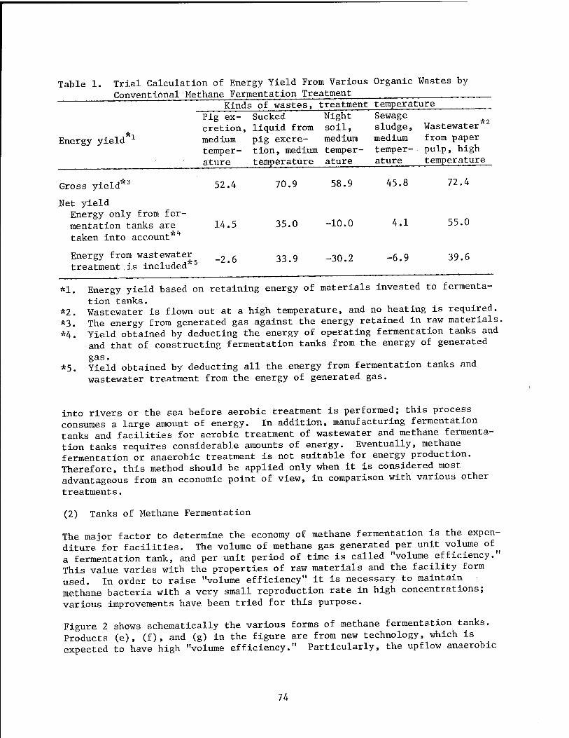
Table 1. Trial Calculation of Energy Yield From Various Organic Wastes by Conventional Methane Fermentation Treatment
Energy yield
Kinds of wastes, treatment temperature Pig ex- Sucked Night Sewage cretion, liquid from soil, sludge, Wastewater medium pig excre- medium medium from paper temper- tion, medium temper- temper- pulp, high ature temperature ature ature temperature
Gross yield 3
Net yield Energy only from fer- mentation tanks are taken into account*h
52.4
14.5
70.9
35.0
58.9
-10.0
Energy from wastewater „ , . ■ i i i*5 ~^.D treatment.is included
33.9 -30.2
45.8
4.1
-6.9
72.4
55.0
39.6
*1.
*2. *3. *4.
*5.
Energy yield based on retaining energy of materials invested to fermenta- tion tanks. Wastewater is flown out at a high temperature, and no heating is required. The energy from generated gas against the energy retained in raw materials. Yield obtained by deducting the energy of operating fermentation tanks and and that of constructing fermentation tanks from the energy of generated
Sas" Yield obtained by deducting all the energy from fermentation tanks and wastewater treatment from the energy of generated gas.
into rivers or the sea before aerobic treatment is performed; this process consumes a large amount of energy. In addition, manufacturing fermentation tanks and facilities for aerobic treatment of wastewater and methane fermenta- tion tanks requires considerable amounts of energy. Eventually, methane fermentation or anaerobic treatment is not suitable for energy production. Therefore, this method should be applied only when it is considered most advantageous from an economic point of view, in comparison with various other treatments.
(2) Tanks of Methane Fermentation
The major factor to determine the economy of methane fermentation is the expen- diture for facilities. The volume of methane gas generated per unit volume of^ a fermentation tank, and per unit period of time is called "volume efficiency." This value varies with the properties of raw materials and the facility form used. In order to raise "volume efficiency" it is necessary to maintain methane bacteria with a very small reproduction rate in high concentrations; various improvements have been tried for this purpose.
Figure 2 shows schematically the various forms of methane fermentation tanks. Products (e), (f), and (g) in the figure are from new technology, which is expected to have high "volume efficiency." Particularly, the upflow anaerobic
74
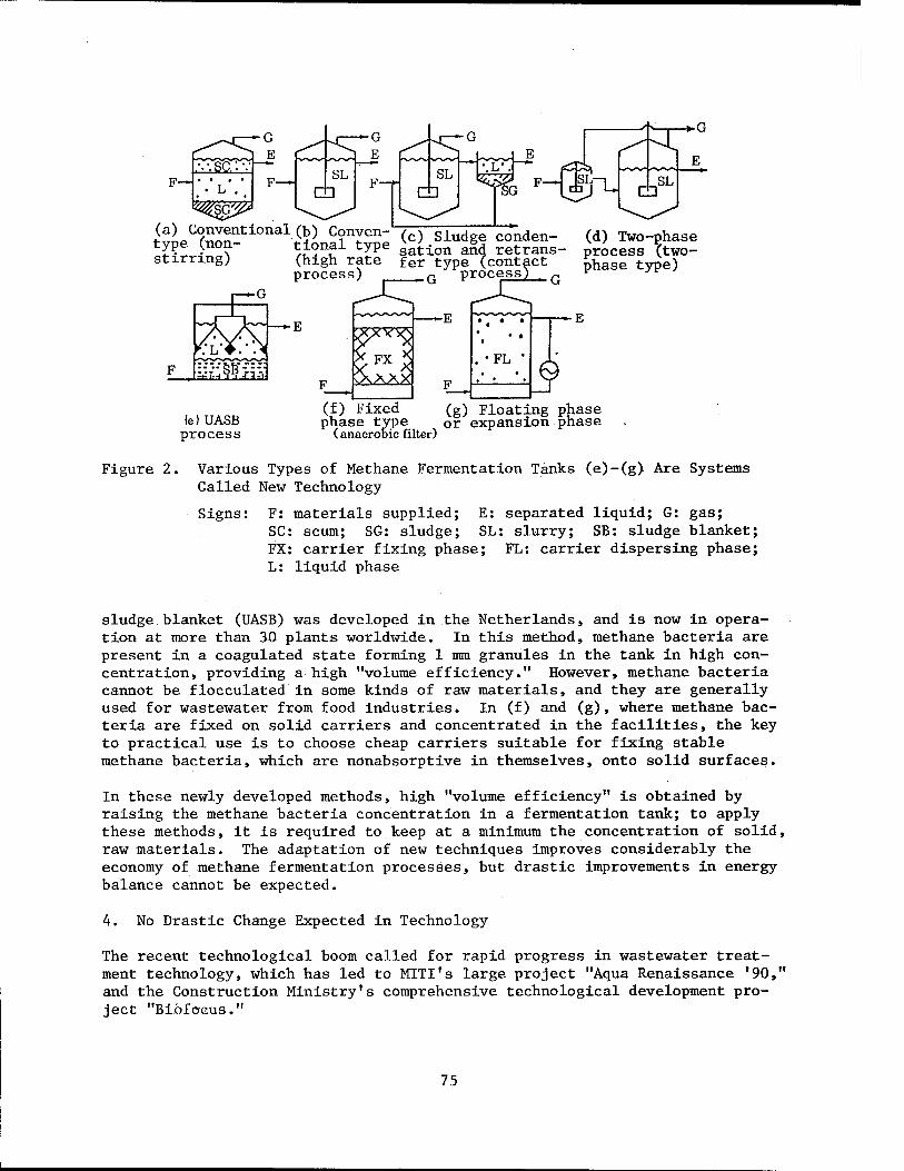
F—
^Lttntxonal (b) Conven- (c) slud conden- (d) Two-phase S® J™?~ M^t1 type sation and retrans- process *two- stimng) (high rate fer type (contact £hase type)
process) _G process) t G ^ ;r
■ G
■E
(e)UASB process
(f) Fixed phase type
(anaerobic fi filter)
(g) Floating phase or expansion phase
Figure 2. Various Types of Methane Fermentation Tanks (e)-(g) Are Systems Called New Technology
Signs: F: materials supplied; E: separated liquid; G: gas; SC: scum; SG: sludge; SL: slurry; SB: sludge blanket; FX: carrier fixing phase; FL: carrier dispersing phase; L: liquid phase
sludge blanket (UASB) was developed in the Netherlands, and is now in opera- tion at more than 30 plants worldwide» In this method, methane bacteria are present in a coagulated state forming 1 mm granules in the tank in high con- centration, providing a high "volume efficiency." However, methane bacteria cannot be flocculated in some kinds of raw materials, and they are generally used for wastewater from food industries. In (f) and (g), where methane bac- teria are fixed on solid carriers and concentrated in the facilities, the key to practical use is to choose cheap carriers suitable for fixing stable methane bacteria, which are nonabsorptive in themselves, onto solid surfaces.
In these newly developed methods, high "volume efficiency" is obtained by raising the methane bacteria concentration in a fermentation tank; to apply these methods, it is required to keep at a minimum the concentration of solid, raw materials. The adaptation of new techniques improves considerably the economy of methane fermentation processes, but drastic improvements in energy balance cannot be expected.
4. No Drastic Change Expected in Technology
The recent technological boom called for rapid progress in wastewater treat- ment technology, which has led to MITI's large project "Aqua Renaissance '90," and the Construction Ministry's comprehensive technological development pro- ject "Bibfocus."
75
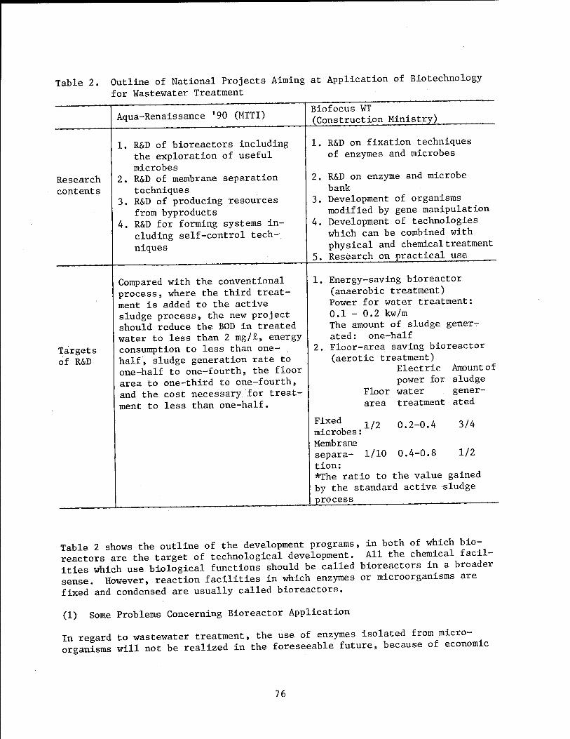
Table 2. Outline of National Projects Aiming at Application of Biotechnology for Wastewater Treatment
Research contents
Targets of R&D
Aqua-Renaissance '90 (MITI)
1. R&D of bioreactors including the exploration of useful microbes
2. R&D of membrane separation techniques
3. R&D of producing resources from byproducts
4. R&D for forming systems in- cluding self-control tech- niques
Compared with the conventional process, where the third treat- ment is added to the active sludge process, the new project should reduce the BOD in treated water to less than 2 mg/£, energy consumption to less than one- half, sludge generation rate to one-half to one-fourth, the floor area to one-third to one-fourth, and the cost necessary for treat- ment to less than one-half.
Biofocus WT (Construction Ministry)
1. R&D on fixation techniques of enzymes and microbes
2. R&D on enzyme and microbe bank
3. Development of organisms modified by gene manipulation
4. Development of technologies which can be combined with physical and chemical treatment
5. Research on practical use
Energy-saving bioreactor (anaerobic treatment) Power for water treatment: 0.1 - 0.2 kw/m The amount of sludge gener- ated: one-half Floor-area saving bioreactor (aerotic treatment)
Electric Amount of power for sludge
Floor water gener- area treatment ated
1/2 0.2-0.4 3/4
1/2
Fixed microbes: Membrane separa- 1/10 0.4-0.8 tion: *The ratio to the value gained by the standard active sludge process .
Table 2 shows the outline of the development programs, in both of which bio- reactors are the target of technological development. All the chemical facil- ities which use biological functions should be called bioreactors in a broader sense. However, reaction facilities in which enzymes or microorganisms are fixed and condensed are usually called bioreactors.
(1) Some Problems Concerning Bioreactor Application
In regard to wastewater treatment, the use of enzymes isolated from micro- organisms will not be realized in the foreseeable future, because of economic
76

reasons. Microorganisms themselves have been already used in a fixed state in the trickling filter method and the rotating-disk method. As shown in Figure 1, they are not very effective, but their power efficiency is relatively high, and are manufactured to cope with the reproduction of fixed microorgan- isms. In the three-phase flexible layer method, fixed microorganisms are condensed in the facility. In this case, the amount of microorganisms in the facility cannot be controlled, and power efficiency decreases as shown in Figure 1.
In these traditional methods, microorganisms are used in a form fixed naturally on a solid surface, but in new bioreactors, microorganisms are included in gel substances and fixed. However, it is doubtful if a stable inclusion-state can be maintained in the aerobic condition, because microorganisms reproduce. While the expenditure for facilities will increase accompanied by inclusion, and oxygen-transfer resistance to microorganisms included in gel substances will increase, the power efficiency will become lower than the active sludge method. Particularly, the operation to control the reproduction of microorgan- isms will further promote this tendency.
(2) Problems in Use of Anaerobic Treatment
As stated previously, more expectations are rising for the anaerobic treatment than for the aerobic treatment regarding energy conservation. Traditionally, anaerobic treatment has been considered a pretreatment for wastewater contain- ing high-level organic substances. The following problems will be brought about if anaerobic treatment is applied to wastewater.
In anaerobic treatment, the rate of decomposition of organic substances per bacteria unit will be reduced to one-third or one-fourth and the facility efficiency will deteriorate when compared to aerobic treatment. BOD of treated water cannot be lowered by anaerobic treatment alone. Aerobic treat- ment will be necessary in the latter stage which will complicate the process. Furthermore, generated gas contains small amounts of methane which cannot be used as fuel. The reduction of generated sludge, which is expected, cannot offset all of these drawbacks.
(3) Difficulty in Applying New Technology
The use of particular microbes and the application of gene manipulation for treating wastewater will be far in the future, if it is possible. Basic prob- lems still remain to be studied, including whether the particular microbes can be maintained and used without a sterilizing process to treat complex, mixed raw materials. Therefore, they are not main targets of technological develop- ment .
Aqua Renaissance '90 suggests the reuse of treated water; in industries, reusable, treated water has already been recycled effectively. The use of membrane separation for this purpose will be an important task for R&D. Regarding municipal sewage, it should be taken into account that the reusable area of treated water is very limited.
77

(4) Necessity To Evaluate Present Technology
In searching for the direction of progress of wastewater treatment, a full analysis of present technology should be performed, and then the problems
must be found.
For instance, as shown in Figure 3, the values of power efficiency by an active sludge process at municipal sewage treatment sites in this country differ from one site to another; this is because practical operating condi- tions vary power efficiency largely, as indicated by the average values of power efficiency predicted theoretically.
®
Figure 3.
2.0 'm3/m3-h
t-pf treatment
10 20 30 40 50 60 70 80 BOD treatment speed per unit volume of the aeration tank in active-sludge process
(g-BOD/m3-h)
Values of Power Efficiency in Facilities for Wastewater Treatment by Active Sludge Process at Municipal Sewage Treatment Plant in Japan
Straight lines and curved lines in the figure show theoretically^ calculated values when facilities are operated in average condition. Straight lines show amount of air flowing into aeration tanks. Broken lines are values when nitration reactions do not occur; while one-dot chained lines are values of power efficiency when nitration reactions take place. There are fluctuations in the data, because the values of measured water quality published at each treatment plant do not always represent the average values measured.
78
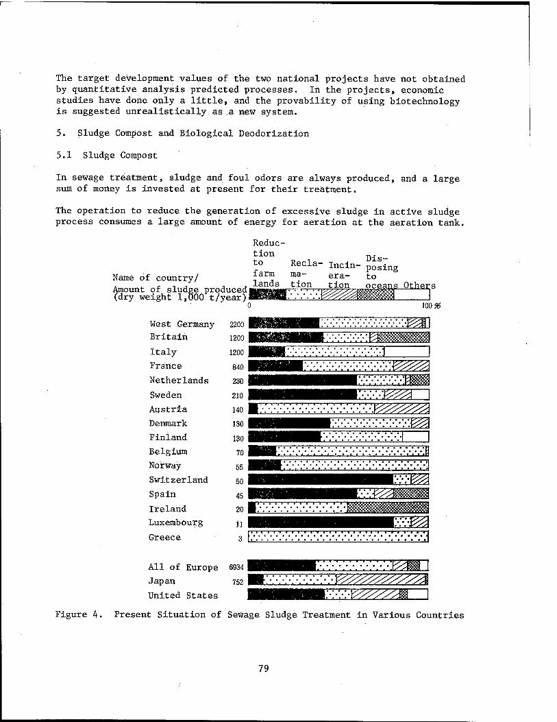
The target development values of the two national projects have not obtained by quantitative analysis predicted processes. In the projects, economic studies have done only a little, and the provability of using biotechnology is suggested unrealistically as a new system.
5. Sludge Compost and Biological Deodorization
5.1 Sludge Compost
In sewage treatment, sludge and foul odors are always produced, and a large sum of money is invested at present for their treatment.
The operation to reduce the generation of excessive sludge in active sludge process consumes a large amount of energy for aeration at the aeration tank.
Reduc- tion to farm
Recla- incin- ma- era-
Dis- posing to Name of country/ -. ,
Amount of sludge produced mS^^.'K^^sM^t °ther|S (dry weight 1,000 t/year)
100 &
West Germany
Britain
Italy
France
Netherlands
Sweden
Austria
Denmark
Finland
Belgium
Norway
Switzerland
Spain
Ireland
Luxembourg
Greece
2200
1200
1200
840
230
210
140
130
130
70
55
50
45
20 |
11
3
« » ■ * -J—1 1—1—I * * ' *' *
v.v.v.v.v.v.v. £%^
II IT I I—I 1 1 "' I I II
^^^1 ^
3
■TTT-TTTTTTT-T~T~m-TT-TTTTT
All of Europe 6934
Japan 752
United States
'i ■ ■ ■—r~
\\-\>\--/,yyyyyyyyyyyy&
Figure 4. Present Situation of Sewage Sludge Treatment in Various Countries
79
Figure 4 shows how municipal sewage sludge is treated in various countries. It shows that reclamation is less in Japan than in other countries. On the other hand, the amount of incineration is larger. In Western countries, a considerable amount of sewage sludge is reduced to farm lands. In sewage sludge, fertilizing materials for farm products are contained, and their reduc- tion to farm lands might be rational in view of material circulation. How- ever, in sewage sludge, heavy metals accumulate accompanied by industrial activities, and are hazardous to farm lands. Moreover, even when the sludge pollution to farm lands is small, sludge must be preserved, until the right time for reducing, or bacteria in the sludge may be a troublesome problem.
A sludge treatment to solve these problems is to make compost. Compost preservable for a long time can be produced by controlling the water-content of sludge below 60 percent, maintaining aeration to proceed active aerobic fermentation. The number of sewage sludge compost plants has increased rapidly in the early 1980s, and now there are about 30 plants. However, most of them are small scale, and the amount of compost produced is very minimal. How to produce cheap compost products which farmers use willingly, along with solving the problem of heavy metals, is a key to the success of sludge compost.
5.2 Biological Deodorization
As the living standard has improved, people have become more sensitive to foul odors. Particularly at wastewater treatment sites, they have the illu- sion at a glance that foul odor emanates from it. Therefore, a foul odor generating sludge treatment process, and even the exhaust gas from an aeration tank have become the targets of odor removal; now the tanks are covered and the exhaust gas is introduced into deodorization equipment with active carbon or detergent containing chemicals. This treatment has further increased the wastewater treatment expenditure.
As an economic treatment for low level foul odors, biological deodorization is now attracting attention. Soil deodorization has been known in a primitive stage, and its practical application is rapidly increasing as shown in Figure 5. However, this method uses microbial activity in the soil, needs a broad floor area, and is not applicable everywhere.
Compared with chemical substances in wastewater, foul odor components which dissipate into the air have simpler chemical structures, and are limited. Therefore, it would not be very difficult to produce a bioreactor, or effec- tive deodorant apparatus which decomposes the components of foul odors very effectively.
The author has succeeded in culturing microbes which effectively decompose foul odor components with the use of.peat as a carrier. With these microbes, a deodorizing apparatus more effective than the soil deodorization will be put into practical use in the near future.
80

100
S 80 •H
•H
cd 60
o u
1 40
20
Sewage treat merit plants Compost factories Public lavatories Rendering factories Excretion treat ment plants Fish-meal factories Dried excret: of livestock
Others
1970 1975 1980
Figure 5. Number of Soil Deodorization Facilities Established in Japan
6. Economy of Biotechnology
Chemical reactions in the living body proceed with enzymatic catalytic reac- tions. Even in today's civilized society, human beings cannot synthesize these catalysts, and experiments to produce them will not succeed for some time. The bioreactor is formed to use enzymes actively or microbes contain- ing enzymes. Reactions in a bioreactor generally proceed at room temperature and under the pressure of one atom, which is economical and energy-saving; it is true so far as wastewater treatment is concerned. Biological treatment, if it is possible, is most economical and energy-saving. This is because wastewater to be treated is a mixture of various organic compounds, which are diluted by a large amount of water, and the reactions to treatment are the relatively simple metabolism of microbes, and oxidation reactions.
On the other hand, in reaction apparatus which is used generally in chemical industries, reaction temperatures and pressures can be controlled arbitrarily to suitable values for the reactions involved. Raw materials can be used in proper concentrations by purifying them at prior stages. When it is necessary to pass several reaction processes before obtaining products from raw mate- rials, different reactions, and suitable reaction conditions can be chosen. In other words, chemical reactions proceed under conditions not restricted as those which occur in cells at room temperature, under 1 atmosphere mixed with raw materials.
Therefore, bioreactors can be used practically only when economical advantages are recognized for the same material, compared with chemical conversions which are described above. The application area will be limited for some time.
81
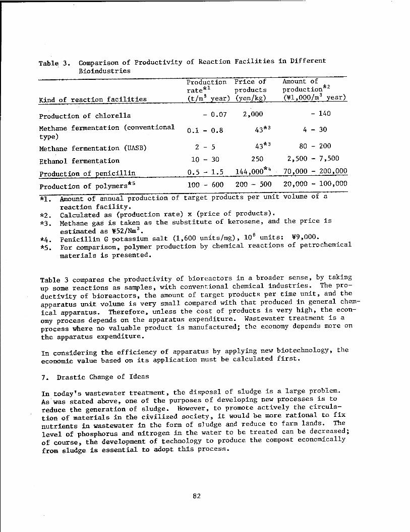
Table 3. Comparison of Productivity of Reaction Facilities in Different Bioindustries
Kind of reaction facilities
Production Price of rate*1 products (t/m3 year) (yen/kg)
Mount of production 2
(¥l,000/m3 year)
Production of Chlorella - 0.07
Methane fermentation (conventional Q ^ _ 0>g type)
Methane fermentation (UASB) 2-5
Ethanol fermentation 10 - 30
Production of penicillin 0*5 - 1.5
2,000
43*3
43*3
250
144,000*"
- 140
4-30
80 - 200
2,500 - 7,500
70,000 - 200,000
Production of polymers *5 100 - 600 200 - 500 20,000 - 100,000
*1. Amount of annual production of target products per unit volume of a reaction facility.
*2. Calculated as (production rate) x (price of products). *3. Methane gas is taken as the substitute of kerosene, and the price is
estimated as ¥52/Nm3. *4. Penicillin G potassium salt (1,600 units/mg), 10 units: ¥9,000. *5. For comparison, polymer production by chemical reactions of petrochemical
materials is presented.
Table 3 compares the productivity of bioreactors in a broader sense, by taking up some reactions as samples, with conventional chemical industries. The pro- ductivity of bioreactors, the amount of target products per time unit, and the apparatus unit volume is very small compared with that produced in general chem- ical apparatus. Therefore, unless the cost of products is very high, the econ- omy process depends on the apparatus expenditure. Wastewater treatment is a process where no valuable product is manufactured; the economy depends more on the apparatus expenditure.
In considering the efficiency of apparatus by applying new biotechnology, the economic value based on its application must be calculated first.
7. Drastic Change of Ideas
In today*s wastewater treatment, the disposal of sludge is a large problem. As was stated above, one of the purposes of developing new processes is to reduce the generation of sludge. However, to promote actively the circula- tion of materials in the civilized society, it would be more rational to fix nutrients in wastewater in the form of sludge and reduce to farm lands. The level of phosphorus and nitrogen in the water to be treated can be decreased; of course, the development of technology to produce the compost economically from sludge is essential to adopt this process.
82
As previously stated, the sewage system is formed to wash away excretions of municipal residents with a large amount of water. But, returning to the starting point, is it possible to form a compost toilet which treats excre- tions without using water? As a water-controlling material, timber is cut down to make sawdust. The expenditure for this can be supplied by sewage rate. It must be possible to form a new wastewater treatment system which does not release nitrogen andphosphorus into the water system at one-fourth the present sewer system cost by combining compost toilets and community septic tanks for various wastewaters. This system will be controlled by sani- tation facility companies, which recover the sludge from toilets and septic tanks to manufacture compost which is sold for profit.
The realization of this system's practical use,which is suitable for medium or small size cities, depends on the drastic change on the part of administra- tion rather than technological development.
BIBLIOGRAPHY
1. Kubota, H. and Fujie, K., "Mathematical Models in Biological Wastewater Treatment," S.E. Jorgensen and M.J. Gromieceds, Elsevier, 1985, p 691.
2. Matsuda, Tomo and Kubota, Hiroshi, WATER TREATMENT TECHNOLOGY, Vol 27 No 3» 1986, p 191.
3. Ibid., ENVIRONMENTAL TECHNOLOGY, Vol 15 No 8, 1986, p 649.
4. Fujiwara, Hiroshi, MONTHLY SEWAGE, Vol 8 No 8, 1985, p 16.
5. Kyozai, Toshinori, Ibid., Vol 9 No 10, 1986, p 14.
6. Fujie,K. and Kubota, H. , WATER RESEARCH, Vol 20, 1986, p 1051.
7. Sasaki,Masayuki and Kubota, Hiroshi, ENVIRONMENTAL INFORMATION SCIENCE, Vol 13 No 4, 1984, p 56.
8. Terasawa.M. , Hirai, M., and Kubota, H., ENVIRONMENTAL TECHNOLOGY, Vol 15 No 7, 1986, p 552.
20,140/9365 CSO: 4306/3684 END
83