Embed Size (px)
Citation preview
International Journal of Advance Engineering and Research Development
Volume 2,Issue 8, August -2015
@IJAERD-2015, All rights Reserved 5
Scientific Journal of Impact Factor(SJIF): 3.134 e-ISSN(O): 2348-4470
p-ISSN(P): 2348-6406
Evaluation of factors affecting cutting forces with CNC Milling using Graph Theory
and Matrix Approach
Mandeep Chahal, Sandeep Malik
Asst. Pro fessor at Department of Mechanical Engineering, HCTM, Kaithal, Haryana, India
Student at HCTM, Kaithal, Haryana, India
Abstract- Machinability aspect is of considerable importance for efficient process planning in manufacturing. In this paper,
graph theoretic approach (GTA) is proposed to evaluate the cutting force during CNC milling. Cutting force is considered as
a machinability attribute during CNC milling to evaluate the effect of several factors and their subfactors. Factors affectin g
the cutting force and their interactions are analyzed by developing a mathematical model using digraph and matrix method.
Permanent function or machinability index is obtained from the matrix model developed from the digraphs. This index value
helps in quantifying the influence of considered factors on cutting force. In the present illustration, factors affecting cutting
force during CNC milling are grouped into five broad factors namely work material, machine tool, cutter runout, penetration
strategies, and tool geometry to be machined. GTA methodology reveals that the machine tool has highest index value.
Therefore, it is the most influencing factor affecting cutting force.
Keywords- Graph theory, Index value, CNC Milling, Cutting Force
1. INTRODUCTION
CNC Milling system serve as an alternative to EDM for making dies or moulds from the hardened tool steels. It produces the
die faster and is also more accurate, because fewer steps result in reduced error stacking. It can result in significantly lo wer
manufacturing costs and times when compared with existing product ion processes and its performance is characterized by a
lot of the machining factors. End milling is the widely used operation for metal removal in a variety of manufacturing
industries including the automobile and aerospace sector where quality is an impo rtant factor in the production of slots,
pockets and moulds/dies (Mike et al, 1999; John and Joseph, 2001).
The use of computer numerical control (CNC) machining centers has expanded rapidly through the years. A great advantage
of the CNC machining center is that it reduces the skill requirements of machine operators . One of the most important yet
least understood operation parameters of a machining operation is the cutting force. In general, this force is thought of as a
3D vector that is represented by three components, namely, the power component, the radial component and the axial
component in the tool coordinate system (Zorev, 1966). Of these three components, the greatest normally is the power
component, which is often called the cutting force. This simplification will be used through the body of this paper. As this
force is of high importance, one might think that theoretical and experimental methods for its determination have been
developed and are thus available in the literature. Unfortunately, this is not the case. When it comes to a possibility of
theoretical determination, the foundation of the force and energy calculations in metal cutting is based upon the over
simplified orthogonal force model known as Merchant’s force circle diagram or a condensed force diagram (Komanduri,
1993; Merchant,2003).
Thus, much effort has been devoted to developing indirect force-measurement tools. When it comes to experimental
determination of the cutting force, there are at least two problems.
1. First and foremost is that the cutting force cannot be measured with reasonable accuracy although this fact has never been
honestly admitted by the specialists in this field. To appreciate the issue, one should consider the results of the joint pro gram
conducted by The International Academy for Production Engineering, and National Institute of Standards and Technology
(NIST) to measure the cutting force in the simplest case of orthogonal cutting (Ivester, 2004). The experiments were carefully
prepared (the same batches of the workpiece (steel AISI 1045), tools, etc.) under the supervision of National Institute of
Standards and Technology (NIST) and rep licated at four different most advanced metal cutting laboratories in the world.
Interestingly, although extraord inary care was taken while performing these experiments, there was significant variation (up
to 50%) in the measured cutting force across these four laboratories. If less care is taken and no laboratory conditions are
available then the accuracy of cutting force measurement be much would worse.
International Journal of Advance Engineering and Research Development (IJAERD)
Volume 2,Issue 8, August -2015, e-ISSN: 2348 - 4470 , print-ISSN:2348-6406
@IJAERD-2015, All rights Reserved 6
2. Second, many tool and cutting inserts manufacturers do not have adequate dynamometric equipment to measure the cutting
force. Many dynamometers used in this field are not properly calibrated because the known literature sources did not present
proper experimental methodology for cutting force measurements using piezoelectric dynamometers (Astakhov and Shvets,
2001).
Out of the various CNC industrial machin ing processes, milling is one of the vital machining op erations. Milling is a
common metal removal operation in industry because of its ability to remove material faster with a reasonably good surface
quality.
The matrix approach is useful in analyzing the graph models expedit iously to derive the system function and index to meet
the objectives. Moreover, representation of graph by a matrix offers ease in computer processing (Jangra et al. 2002). This
paper reveals the utilization of graph theoretic approach (GTA) to determine the factors affecting cutting force with CNC
Milling. Various factors, sub-factors and their interdependencies that affect the cutting force is prepared by a digraph and
demonstrated by a matrix. A numeric value named as index value (MI) has been calculated to evaluate the cutting force. A
detailed literature review has been done to determine the various factors and sub-factors that affect the cutting force under
different machining methods. Experimental results and the methodology based on graph theory to evaluate the Index value
have been discussed in the later sections.
2 LITERATURE REVIEW
In order to achieve the objectives of this research a literature rev iew was conducted. The literature involved information on
Graph theory and Matrix method used in various field of science and technology and also on the behavior of cutting force
during machining.
Lou et al. (1999) carried out experimentation to evaluate that feed rate was the most significant machin ing parameter used to
predict the SR in the multip le regression models. Toh (2006) investigated and evaluated the different cutter path orientations
when high-speed finish milling hardened steel, and the results demonstrated that vertical upward orientation has been
generally preferred in terms of workpiece SR. Zhang et al. (2007) suggested that Milling has been one of the most widely
used metal removal processes in industry and milled surfaces are largely used to mate with other parts in die, aerospace,
automotive and machinery design as well as in manufacturing industries. Heinz A Preisig (2007) Suggested A Graph-Theory-
Base Approach to the Analysis of Large-Scale Plants On-line balancing of mass and energy in a large-scale plant. Gologlu and Sakarya (2008) studied that Milling of machining parts could be accomplished by employing different cutter
path strategies (step over), which were one direction, back and forth and spiral cutter path strategies. Viktor P. Astakhov and
Xinran Xiao (2008). Huang et al. (2012) developed a hybrid graph theory and GA approach to process planning for a
prismat ic part within the context of CAPP. Jaime Cerda Jacobo et al. (2012) provide A Graph-based Method to Solve the
Economical Dispatch Problem Disregarding Slack Variab les One of the greatest challenges to confront Nonlinear
Programming Problems; it is the selection of the active and non active set of constraints of the system.
Srishti Sabharwal and Suresh Garg(2013). Determining cost effectiveness index of remanufactur ing: A graph theoretic
approach Remanufacturing is a powerful product recovery option which generates products as good as new ones . Rajesh Attri
and Sandeep Grover (2013). Application of preference selection index method for decision making over the design stage of
production system life cycle The life cycle of production system shows the progress of production system from the inception
to the termination of the system. During each stage, mainly in the design stage, certain strategic decisions have to be taken.
Vinay Babu Gada et al. (2013) In the present study, an attempt has been made to investigate the effect of primary cutting
parameters (cutting speed, feed and depth of cut) and tool overhang length on cutting forces and chatter starting point lengths
in finish turning of EN8 steel, EN24 steel, M ild steel and alumin ium.
Nikhil Dev et. al (2014). Provide A systematic approach based on graph theory and matrix method was de veloped
ingeniously for the evaluation of reliability index fo r a Combined Cycle Power Plant (CCPP). In present work CCPP system
is divided into six subsystems. Consideration of all these subsystems and their interrelations are rudiment in evaluating the
index. Reliability of CCPP is modelled in terms of a Reliability Attributes Digraph.
Vishal S. Sharma et al. (2014) were Investigated the tool geometry effect and penetration strategies on cutting forces during
thread milling. The application of thread milling is increasing in industry because of its inherent advantages over other thread
cutting techniques. The objective of this study is to investigate the effect of milling cutter tool geometry on cutting forces
during thread milling. The proposed method can compare the performance of milling cutters in spite of the different number
of tooth. The best thread milling cutter among the studied tools was determined from the cutting forces point of view.
Furthermore, this study also pinpoints the best penetration strategy that provides min imum cutting forces. Lower cutting
force variat ions will lead to fewer vibrat ions of the tool which in turn will produce accurate part.
International Journal of Advance Engineering and Research Development (IJAERD)
Volume 2,Issue 8, August -2015, e-ISSN: 2348 - 4470 , print-ISSN:2348-6406
@IJAERD-2015, All rights Reserved 7
Based on the detailed literature related to the machining of tool steels and other hard materials, various factors and sub-
factors have been identified which affect the cutting force during machin ing with CNC Milling. Tab le1 summarize these
factors and sub-factors.
Problem Identification
1. Literature review reveals that researchers have carried out most of the work with AHP (analytic hierarchy
process), ANN (art ificial neural network), DOE (design of experiment), Taguchi method and RSM
(Response surface methodology) but very limited work has been reported with Graph theory and Matrix
approach.
2. Very limited work has been reported to evaluate the cutting force on CNC Milling by using graph theory
and matrix approach.
3. Most of the researchers have applied Graph Theory to evaluate the surface roughness and MRR. Here I am
applying Graph Theory to evaluate cutting force during CNC Milling.
3 GTA
The beginning of Graph theory is said to have in 1736 when EULER considered the Konigsberg bridge problem.
Subsequently, the graph theory has been applied in various fields of engineering such as physics, chemistry, mathematics,
electrical engineering, sociology, computer technology (net working), economics, operation research, etc.
Graph theoretic approach (GTA) is a systematic methodology for conversion of qualitative factors to quantitative values and
mathematical modeling gives an edge to the proposed technique over conventional methods like cause -effect diagrams, flow
charts etc. Graph theory serves as a mathematical model of any system that includes multi relations among its constituent
elements because of its diagrammat ic representations and aesthetic aspects. GTA is a three stage unified systems approach
(Deb, 2000).
(i). Modeling of systems in terms of nodes and edges gives a structural representation to the system and results in a directe d
graph. This representation is suitable for visual analysis and understanding the interrelationships among various nodes.
(ii). For further analysis, digraph representation is converted to matrix form, which makes it suitable for computer processing.
However the matrix representation is not unique as changing the labeling of nodes can change it.
(iii). Analysis of matrix model results in permanent function model, which is in the expression form. The permanent function
model analyzes various combinations among the factors and interrelationships. Simplified permanent function expression is
represented in terms of a single numerical index.
Using graph theoretic approach, several attempts have been made to solve the industrial problems involving multi variables
having interaction among them (Wani and Gandhi, 1999; Rao and Gandhi, 2002, 2006; Grover et al., 2004; Jangra et al.,
2011).
3.1 Methodology
The various steps involved in graph theoretic approach are enlisted in sequential manner as below:
1.Identify the various sub-systems affecting the main system.
2.Logically develop a d iagraph between the system/sub-system depending upon their
interdependencies.
3. Develop a variable permanent function matrix at the sub-system level on the basis of digraph developed in step 2. Matrix
representation of the alternative selection criteria digraph gives one-to-one representation. A matrix called the equipment
selection criteria matrix. This is an M in M matrix and considers all of the criteria (i.e. A i) and their relative importance (i.e.
aij). Where Ai is the value of the i-th criteria represented by node n i and aij is the relative importance of the i-th criteria over
the j-th represented by the edge eij (Rao, 2007; Faisal et al., 2007).
The value of A i should preferably be obtained from available or estimated data. When quantitat ive values of the criteria are
available, normalized values of a criterion assigned to the alternatives are calculated by v i/vj, where vi is the measure of the
criterion for the i-th alternative and vj is the measure of the criterion for the j-th alternative which has a higher measure of the
criterion among the considered alternatives. This ratio is valid fo r beneficial criteria only. A beneficial criteria means it s
higher measures are more desirable for the given application. Whereas, the non -beneficial criterion is the one whose lower
measures are desirable and the normalized values assigned to the alternatives are calculated by v j/vi.
International Journal of Advance Engineering and Research Development (IJAERD)
Volume 2,Issue 8, August -2015, e-ISSN: 2348 - 4470 , print-ISSN:2348-6406
@IJAERD-2015, All rights Reserved 8
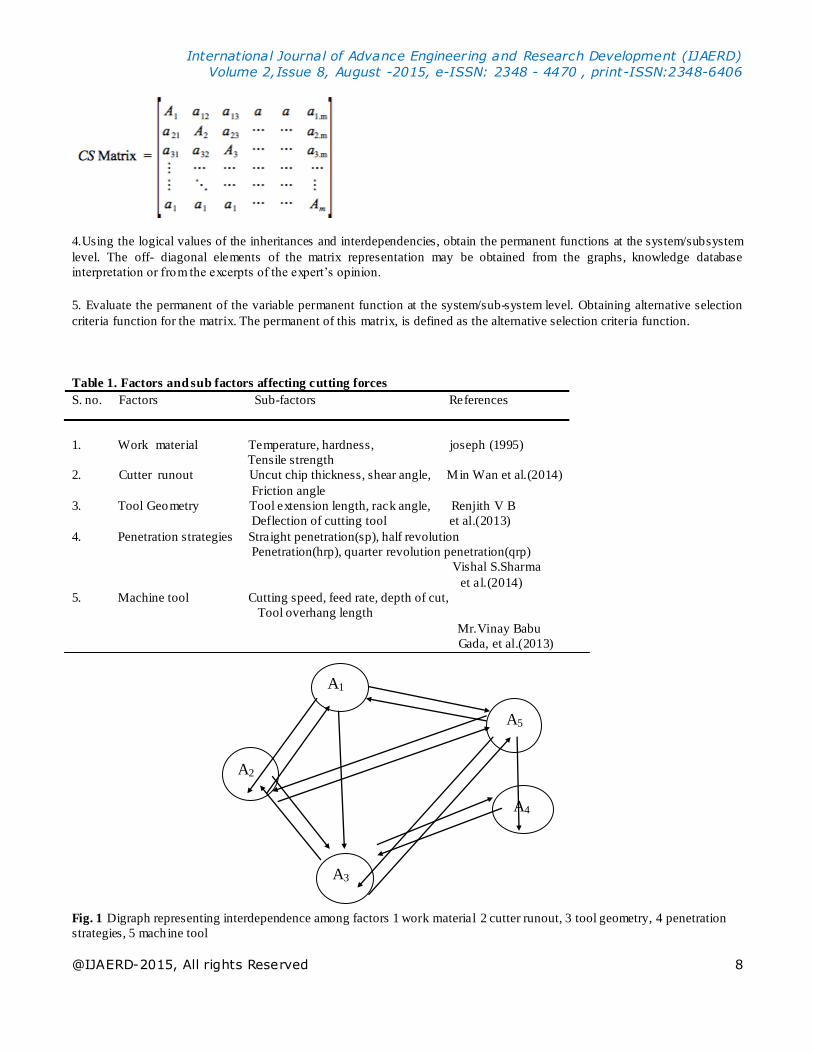
4.Using the logical values of the inheritances and interdependencies, obtain the permanent functions at the system/subsystem
level. The off- diagonal elements of the matrix representation may be obtained from the graphs, knowledge database
interpretation or from the excerpts of the expert’s opinion.
5. Evaluate the permanent of the variable permanent function at the system/sub-system level. Obtaining alternative selection
criteria function for the matrix. The permanent of this matrix, is defined as the alternative selection criteria function.
Table 1. Factors and sub factors affecting cutting forces
S. no. Factors Sub-factors References
1. Work material Temperature, hardness, joseph (1995)
Tensile strength
2. Cutter runout Uncut chip thickness, shear angle, Min Wan et al.(2014)
Friction angle
3. Tool Geometry Tool extension length, rack angle, Renjith V B
Deflection of cutting tool et al.(2013)
4. Penetration strategies Straight penetration(sp), half revolution
Penetration(hrp), quarter revolution penetration(qrp)
Vishal S.Sharma
et al.(2014)
5. Machine tool Cutting speed, feed rate, depth of cut,
Tool overhang length
Mr.Vinay Babu
Gada, et al.(2013)
Fig. 1 Digraph representing interdependence among factors 1 work material 2 cutter runout, 3 tool geometry, 4 penetration
strategies, 5 machine tool
A1
A5
A4
A3
A2
International Journal of Advance Engineering and Research Development (IJAERD)
Volume 2,Issue 8, August -2015, e-ISSN: 2348 - 4470 , print-ISSN:2348-6406
@IJAERD-2015, All rights Reserved 9
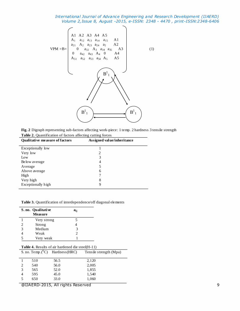
A1 A2 A3 A4 A5
A1 a12 a13 a14 a15 A1
a21 A2 a23 a24 a2 A2
VPM =B= 0 a32 A3 a34 a35 A3 (1)
0 a42 a43 A4 0 A4
A51 a52 a53 a54 A5 A5
Fig. 2 Digraph representing sub-factors affecting work-piece: 1 temp. 2 hardness 3 tensile strength
Table 2. Quantification of factors affecting cutting forces
Qualitative measure of factors Assigned value/inheritance
Exceptionally low 1
Very low 2
Low 3
Below average 4
Average 5
Above average 6
High 7
Very high 8
Exceptionally h igh 9
Table 3. Quantification of interdependence/off diagonal elements
S. no. Qualitative aij
Measure
1 Very strong 5
2 Strong 4
3 Medium 3
4 Weak 2
5 Very weak 1
Table 4. Results of air hardened die steel(H-11)
S. no. Temp.(0C) Hardness(HRC) Tensile strength (Mpa)
1 510 56.5 2,120
2 540 56.0 2,005
3 565 52.0 1,855
4 595 45.0 1,540
5 650 33.0 1,060
B11
B11 B1
1
International Journal of Advance Engineering and Research Development (IJAERD)
Volume 2,Issue 8, August -2015, e-ISSN: 2348 - 4470 , print-ISSN:2348-6406
@IJAERD-2015, All rights Reserved 10
Results are taken from joseph (1995)
3.5 Index value for work material (A1)
Sub factors affecting work material and their interactions have been illustrated with the help of d igraph as in Fig.2
Table 5. Inheritance of sub-factors for work material (diagonal elements)
S. no. Temperature(B1
1) Hardness (B1
2) Tensile strength (B1
3)
1 6 5 7
2 7 6 7
3 9 7 6
4 5 7 4
5 4 7 4
Table 6. Index Value for work piece for d ifferent combination
Subsystem with d ifferent sub (A1)1 (A1)2 (A1)3 (A1)4 (A1)5
factor combination
Index value 483 585 680 380 344
The superscript represents the factor and the subscript represents the sub factors affecting factor (work -piece). Experimental
data proposed by Joseph (Joseph and Tool Materials 1995) has been used to evaluate the inheritance of diagonal elements.
The results show the significant effect that temperature has on hardness and tensile strength of die steels.
At higher temperatures, the die steels start losing their hardness and tensile strength. The inheritance of sub -factors has been
assigned value in range of 1–9 as shown in Table 5 with the help of Table 2.
The VPM for each sub-system based on digraph showing their inter-relationship have been developed and based on detailed
literature rev iew, the numeric values of interdependences between sub-factors (non-diagonal elements) have been taken from
Table 3.
Value of permanent function for work material (A1) can be calculated using Eq.3.
1 2 3
B1
1 3 2 1
VPM = A1 = 5 B1
2 2 2 (3)
5 4 B1
3 3
Higher values of index reflect the best conditions of cutting force, because at 5650C the die steel maintains optimum hardness
and tensile strength (Table 6).
3.6 Index value for Cutter runout (A2)
B21
B23 B2
2
International Journal of Advance Engineering and Research Development (IJAERD)
Volume 2,Issue 8, August -2015, e-ISSN: 2348 - 4470 , print-ISSN:2348-6406
@IJAERD-2015, All rights Reserved 11
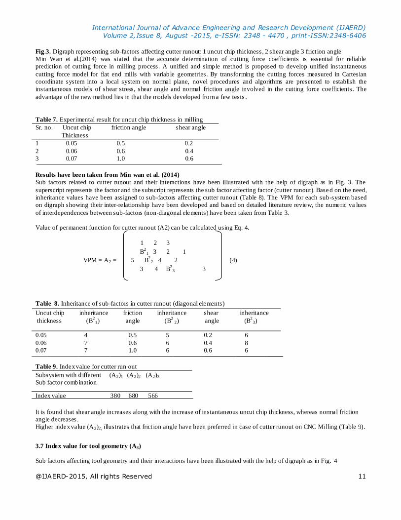
Fig.3. Digraph representing sub-factors affecting cutter runout: 1 uncut chip thickness, 2 shear angle 3 frict ion angle
Min Wan et al.(2014) was stated that the accurate determination of cutting force coefficients is essential for reliable
prediction of cutting force in milling process. A unified and simple method is proposed to develop unified instantaneous
cutting force model for flat end mills with variab le geometries. By transforming the cutting forces measured in Cartesian
coordinate system into a local system on normal plane, novel procedures and algorithms are presented to establish the
instantaneous models of shear stress, shear angle and normal friction angle involved in the cutting force coefficients. The
advantage of the new method lies in that the models developed from a few tests .
Table 7. Experimental result for uncut chip thickness in milling
Sr. no. Uncut chip friction angle shear angle
Thickness
1 0.05 0.5 0.2
2 0.06 0.6 0.4
3 0.07 1.0 0.6
Results have been taken from Min wan et al. (2014)
Sub factors related to cutter runout and their interactions have been illustrated with the help of digraph as in Fig. 3. The
superscript represents the factor and the subscript represents the sub factor affecting factor (cutter runout). Based on the need,
inheritance values have been assigned to sub-factors affecting cutter runout (Table 8). The VPM for each sub-system based
on digraph showing their inter-relationship have been developed and based on detailed literature review, the numeric va lues
of interdependences between sub-factors (non-diagonal elements) have been taken from Table 3.
Value of permanent function for cutter runout (A2) can be calculated using Eq. 4.
1 2 3
B2
1 3 2 1
VPM = A2 = 5 B2
2 4 2 (4)
3 4 B2
3 3
Table 8. Inheritance of sub-factors in cutter runout (diagonal elements)
Uncut chip inheritance friction inheritance shear inheritance
thickness (B2
1) angle (B2
2) angle (B2
3)
0.05 4 0.5 5 0.2 6
0.06 7 0.6 6 0.4 8
0.07 7 1.0 6 0.6 6
Table 9. Index value for cutter run out
Subsystem with d ifferent (A2)1 (A2)2 (A2)3
Sub factor combination
Index value 380 680 566
It is found that shear angle increases along with the increase of instantaneous uncut chip thickness, whereas normal friction
angle decreases.
Higher index value (A2)2, illustrates that frict ion angle have been preferred in case of cutter runout on CNC Milling (Table 9).
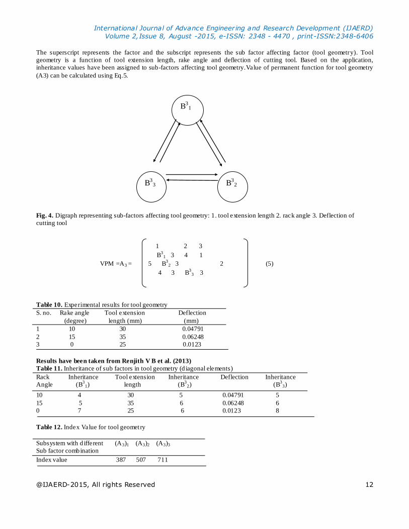
3.7 Index value for tool geometry (A3)
Sub factors affecting tool geometry and their interactions have been illustrated with the help of d igraph as in Fig. 4
International Journal of Advance Engineering and Research Development (IJAERD)
Volume 2,Issue 8, August -2015, e-ISSN: 2348 - 4470 , print-ISSN:2348-6406
@IJAERD-2015, All rights Reserved 12
The superscript represents the factor and the subscript represents the sub factor affecting factor (tool geometry). Tool
geometry is a function of tool extension length, rake angle and deflection of cutting tool. Based on the application,
inheritance values have been assigned to sub-factors affecting tool geometry.Value of permanent function for tool geometry
(A3) can be calculated using Eq.5.
Fig. 4. Digraph representing sub-factors affecting tool geometry: 1. tool extension length 2. rack angle 3. Deflection of
cutting tool
1 2 3
B3
1 3 4 1
VPM =A3 = 5 B3
2 3 2 (5)
4 3 B3
3 3
Table 10. Experimental results for tool geometry
S. no. Rake angle Tool extension Deflection
(degree) length (mm) (mm)
1 10 30 0.04791
2 15 35 0.06248
3 0 25 0.0123
Results have been taken from Renjith V B et al. (2013)
Table 11. Inheritance of sub factors in tool geometry (d iagonal elements)
Rack Inheritance Tool extension Inheritance Deflection Inheritance
Angle (B3
1) length (B3
2) (B3
3)
10 4 30 5 0.04791 5
15 5 35 6 0.06248 6
0 7 25 6 0.0123 8
Table 12. Index Value for tool geometry
Subsystem with d ifferent (A3)1 (A3)2 (A3)3
Sub factor combination
Index value 387 507 711
B31
B33 B3
2
International Journal of Advance Engineering and Research Development (IJAERD)
Volume 2,Issue 8, August -2015, e-ISSN: 2348 - 4470 , print-ISSN:2348-6406
@IJAERD-2015, All rights Reserved 13
Putting the value of diagonal elements, index under different combinations can be calculated.
Higher value of (MI) indicates that cutter having rake angle of 0 and tool extension length of
25 is usually preferred which give min imum deflection i.e. 0.0123 mm.
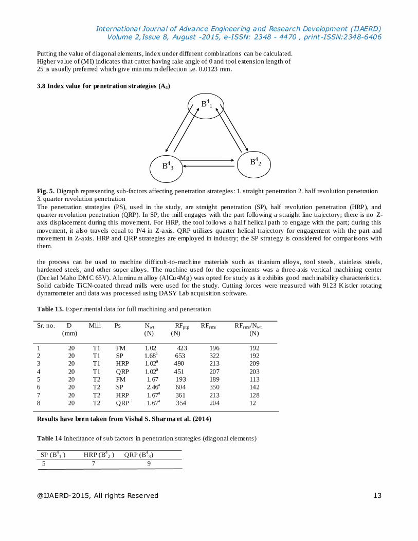
3.8 Index value for penetration strategies (A4)
Fig. 5. Digraph representing sub-factors affecting penetration strategies : 1. straight penetration 2. half revolution penetration
3. quarter revolution penetration
The penetration strategies (PS), used in the study, are straight penetration (SP), half revolution penetration (HRP), and
quarter revolution penetration (QRP). In SP, the mill engages with the part following a straight line trajectory; there is no Z-
axis displacement during this movement. For HRP, the tool fo llows a hal f helical path to engage with the part; during this
movement, it also travels equal to P/4 in Z-axis. QRP utilizes quarter helical t rajectory for engagement with the part and
movement in Z-axis. HRP and QRP strategies are employed in industry; the SP strategy is considered for comparisons with
them.
the process can be used to machine difficult-to-machine materials such as titanium alloys, tool steels, stainless steels,
hardened steels, and other super alloys. The machine used for the experiments was a three-axis vertical machining center
(Deckel Maho DMC 65V). A luminum alloy (AlCu4Mg) was opted for study as it exhibits good machinability characteristics.
Solid carbide TiCN-coated thread mills were used for the study. Cutting forces were measured with 9123 K istler rotating
dynamometer and data was processed using DASY Lab acquisition software.
Table 13. Experimental data for full machining and penetration
Sr. no. D Mill Ps Nwt RFptp RFrms RFrms/Nwt
(mm) (N) (N) (N)
1 20 T1 FM 1.02 423 196 192
2 20 T1 SP 1.68a 653 322 192
3 20 T1 HRP 1.02a 490 213 209
4 20 T1 QRP 1.02a 451 207 203
5 20 T2 FM 1.67 193 189 113
6 20 T2 SP 2.46a
604 350 142
7 20 T2 HRP 1.67a
361 213 128
8 20 T2 QRP 1.67a 354 204 12
Results have been taken from Vishal S. Sharma et al. (2014)
Table 14 Inheritance of sub factors in penetration strategies (diagonal elements)
SP (B4
1 ) HRP (B4
2 ) QRP (B4
3)
5 7 9
B41
B43
B42
International Journal of Advance Engineering and Research Development (IJAERD)
Volume 2,Issue 8, August -2015, e-ISSN: 2348 - 4470 , print-ISSN:2348-6406
@IJAERD-2015, All rights Reserved 14
Vishal S. Sharma et al (2014). Various types of Penetration strategies have been illustrated with the help of digraph as in Fig.
5. Here the superscript represents the factor and the subscript represents the sub factor affecting factor (Penetration strat egies)
(Tables 10, 11, 12,13, 14).
Value of permanent function for Penetration strategies (A4) can be calculated using Eq. 6.
1 2 3
B4
1 1 2 1
VPM = A4 = 2 B4
2 1 2 (6)
2 2 B4
3 3
Index value for Eq. (6) is 380.
1.St raight penetration leads to more resultant cutting forces as compared to half revolution penetration and quarter revolution
penetration strategies for all the three milling cutters because flute working angle (θ twa) becomes double at the end of
penetration strategy.
2.The cutting forces are min imum for quarter revolution penetration because of progressive increase of radial penetration (rp)
and the number of working teeth (Nwt).
3.The peak to peak variations of the resultant cutting force is linked to the number or working teeth, and according to this
criterion T2 mill appears to be the best among the studied tools.
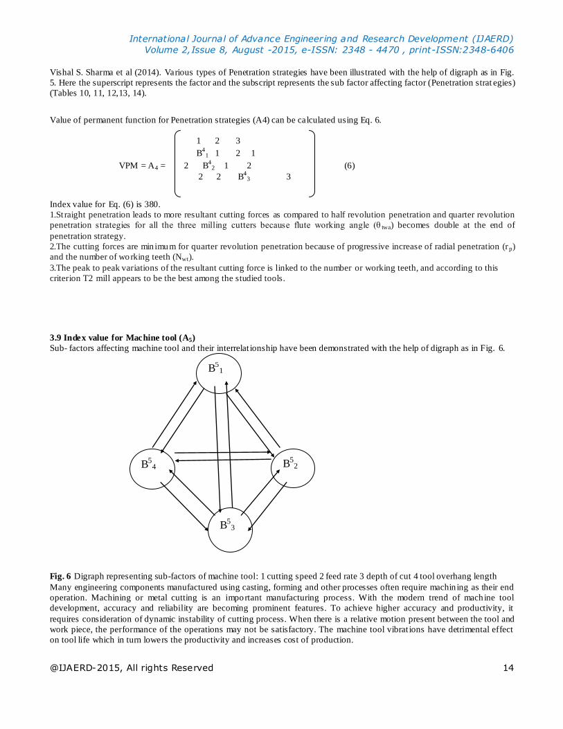
3.9 Index value for Machine tool (A5)
Sub- factors affecting machine tool and their interrelat ionship have been demonstrated with the help of digraph as in Fig. 6.
Fig. 6 Digraph representing sub-factors of machine tool: 1 cutting speed 2 feed rate 3 depth of cut 4 tool overhang length Many engineering components manufactured using casting, forming and other processes often require machin ing as their end
operation. Machining or metal cutting is an important manufacturing process. With the modern trend of machine tool
development, accuracy and reliability are becoming prominent features. To achieve higher accuracy and productivity, it
requires consideration of dynamic instability of cutting process. When there is a relative motion present between the tool and
work piece, the performance of the operations may not be satisfactory. The machine tool vibrat ions have detrimental effect
on tool life which in turn lowers the productivity and increases cost of production.
B51
B52 B5
4
B53
International Journal of Advance Engineering and Research Development (IJAERD)
Volume 2,Issue 8, August -2015, e-ISSN: 2348 - 4470 , print-ISSN:2348-6406
@IJAERD-2015, All rights Reserved 15
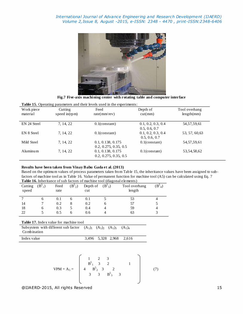
Fig.7 Five-axis machining center with rotating table and computer interface
Table 15. Operating parameters and their levels used in the experiments:
Work piece Cutting Feed Depth of Tool overhang
material speed in(rpm) rate(mm/rev) cut(mm) length(mm)
EN 24 Steel 7, 14, 22 0.1(constant) 0.1, 0.2, 0.3, 0.4 54,57,59,61
0.5, 0.6, 0.7
EN 8 Steel 7, 14, 22 0.1(constant) 0.1, 0.2, 0.3, 0.4 53, 57, 60,63
0.5, 0.6, 0.7
Mild Steel 7, 14, 22 0.1, 0.138, 0.175 0.1(constant) 54,57,59,61
0.2, 0.275, 0.35, 0.5
Aluminum 7, 14, 22 0.1, 0.138, 0.175 0.1(constant) 53,54,58,62
0.2, 0.275, 0.35, 0.5
Results have been taken from Vinay Babu Gada et al. (2013)
Based on the optimum values of process parameters taken from Table 15, the inheritance values have been assigned to sub-
factors of machine tool as in Table 16. Value of permanent function for machine tool (A5) can be calculated using Eq. 7
Table 16. Inheritance of sub factors of machine tool (diagonal elements)
Cutting (B5
1) Feed (B5
2) Depth of (B5
3) Tool overhang (B5
4)
speed rate cut length
7 6 0.1 6 0.1 5 53 4
14 7 0.2 8 0.2 6 57 5
18 6 0.3 5 0.4 4 59 4
22 5 0.5 6 0.6 4 63 3
Table 17. Index value for machine tool
Subsystem with different sub factor (A5)1 (A5)2 (A5)3 (A5)4
Combination
Index value 3,496 5,328 2,968 2,616
1 2 3
B5
1 3 2 1
VPM = A5 = 4 B5
2 3 2 (7)
3 3 B5
3 3
International Journal of Advance Engineering and Research Development (IJAERD)
Volume 2,Issue 8, August -2015, e-ISSN: 2348 - 4470 , print-ISSN:2348-6406
@IJAERD-2015, All rights Reserved 16
Index value indicates that feed rate is the most significant sub factor affecting cutting force, fo llowed by cutting speed ,d epth
of cut and tool overhang length. (Tables 16, 17).
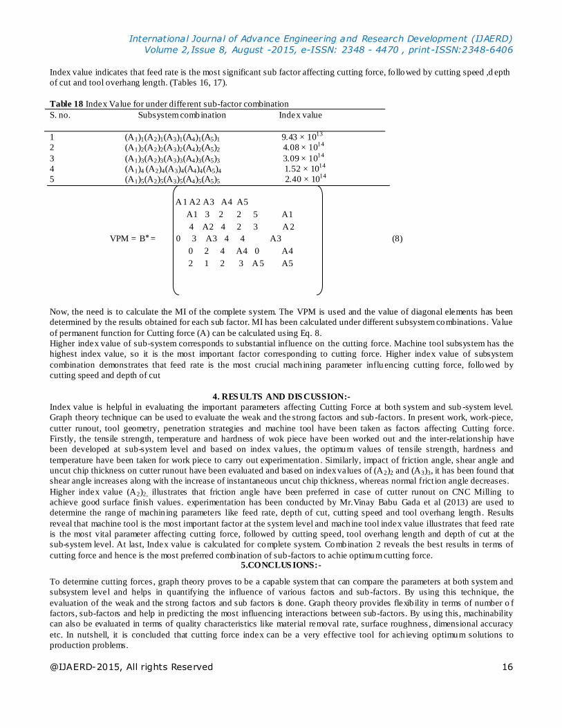
Table 18 Index Value for under different sub-factor combination
S. no. Subsystem combination Index value
1 (A1)1(A2)1(A3)1(A4)1(A5)1 9.43 × 10¹³
2 (A1)2(A2)2(A3)2(A4)2(A5)2 4.08 × 10¹⁴
3 (A1)3(A2)3(A3)3(A4)3(A5)3 3.09 × 10¹⁴
4 (A1)4 (A2)4(A3)4(A4)4(A5)4 1.52 × 10¹⁴
5 (A1)5(A2)5(A3)5(A4)5(A5)5 2.40 × 10¹⁴
A1 A2 A3 A4 A5
A1 3 2 2 5 A1
4 A2 4 2 3 A2
VPM = B3 0 =٭ A3 4 4 A3 (8)
0 2 4 A4 0 A4
2 1 2 3 A5 A5
Now, the need is to calculate the MI of the complete system. The VPM is used and the value of diagonal elements has been
determined by the results obtained for each sub factor. MI has been calculated under different subsystem combinations. Value
of permanent function for Cutting force (A) can be calculated using Eq. 8.
Higher index value of sub-system corresponds to substantial influence on the cutting force. Machine tool subsystem has the
highest index value, so it is the most important factor corresponding to cutting force. Higher index value of subsystem
combination demonstrates that feed rate is the most crucial machining parameter influ encing cutting force, followed by
cutting speed and depth of cut
4. RES ULTS AND DIS CUSSION:-
Index value is helpful in evaluating the important parameters affecting Cutting Force at both system and sub -system level.
Graph theory technique can be used to evaluate the weak and the strong factors and sub -factors. In present work, work-piece,
cutter runout, tool geometry, penetration strategies and machine tool have been taken as factors affecting Cutting force.
Firstly, the tensile strength, temperature and hardness of wok piece have been worked out and the inter-relat ionship have
been developed at sub-system level and based on index values, the optimum values of tensile strength, hardness and
temperature have been taken for work piece to carry out experimentation . Similarly, impact of friction angle, shear angle and
uncut chip thickness on cutter runout have been evaluated and based on index values of (A2)2 and (A3)3, it has been found that
shear angle increases along with the increase of instantaneous uncut chip thickness, whereas normal frict ion angle decreases.
Higher index value (A2)2, illustrates that friction angle have been preferred in case of cutter runout on CNC Milling to
achieve good surface finish values. experimentation has been conducted by Mr.Vinay Babu Gada et al (2013) are used to
determine the range of machin ing parameters like feed rate, depth of cut, cutting speed and tool overhang length . Results
reveal that machine tool is the most important factor at the system level and machine tool index value illustrates that feed rate
is the most vital parameter affecting cutting force, followed by cutting speed, tool overhang length and depth of cut at the
sub-system level. At last, Index value is calculated for complete system. Combination 2 reveals the best results in terms of
cutting force and hence is the most preferred combination of sub-factors to achie optimum cutting force. 5.CONCLUS IONS:-
To determine cutting forces , graph theory proves to be a capable system that can compare the parameters at both system and
subsystem level and helps in quantifying the influence of various factors and sub-factors. By using this technique, the
evaluation of the weak and the strong factors and sub factors is done. Graph theory provides flexib ility in terms of number o f
factors, sub-factors and help in predicting the most influencing interactions between sub-factors. By using this, machinability
can also be evaluated in terms of quality characteristics like material removal rate, surface roughness, dimensional accuracy
etc. In nutshell, it is concluded that cutting force index can be a very effective tool for ach ieving optimum solutions to
production problems.
International Journal of Advance Engineering and Research Development (IJAERD)
Volume 2,Issue 8, August -2015, e-ISSN: 2348 - 4470 , print-ISSN:2348-6406
@IJAERD-2015, All rights Reserved 17
6. SCOPE FOR FUTURE WORK
1. Using this methodology, machinability of any material can be evaluated and compared under the influence of any
number of factors and subfactors.
2. Similar to this methodology, machinability can be evaluated in terms of other machining performances such as
surface finish, dimensional precision, tool life, etc.
REFERENCES
[1] Joseph R.D, Tool Materials, 1995, P.138
[2] Xiong Yao et al.(2013) Machining process parameters optimization for heavy-duty CNC machine tools in sustainable
manufacturing Int J Adv Manuf Technol DOI 10.1007/s00170-013-4881-5
[3] Huang Weijun et al.(2012) An effective hybrid graph and genetic algorithm approach to process planning optimization for
prismat ic parts Int J Adv Manuf Technol (2012) 62:1219–1232 DOI 10.1007/s00170-011-3870-9
[4] GUPTA Meenu, GILL Surinder Kumar (2012) Predict ion of cutting force in turning of UD-GFRP using mathemat ical
model and simulated annealing Front. Mech. Eng. 2012, 7(4): 417–426 DOI 10.1007/s11465-012-0343-2
[5] Gada Vinay Babu et al. (2013) evaluated The Impact of Cutting Conditions on Cutting forces and Chatter Length for
Steel and Aluminum International Journal of Engineering and Advanced Technology (IJEAT) ISSN: 2249 – 8958,
Volume-2, Issue-4, April 2013, April 2013
[6] S. Sharma Vishal et al. (2014) Investigation of tool geometry effect and penetration strategies on cutting forces during
thread milling. International Journal of Advanced Manufacturing Technology, Springer Verlag (Ger-many), 2014, 74
(2014), pp.913. <hal-01066294>
[7] V.B Renjith et al. (2013) Influence of process parameters on cutting forces and
Taguchi based prediction of T42 - CT H.S.S single point cutting tool deflection. International Journal of Scientific and
Research Publicat ions, Volume 3, Issue 7, July 2013 1 ISSN 2250-315.
[8] Haizhen WANG et.al (2012) optimization of gas drainage system in coal mine Procedia Engineering 45 ( 2012 ) 339 –
344
[9] Laus L.P. et. al (2012) Efficiency of gear trains determined using graph and screw theories .
[10] Mechanism and Machine Theory 52 (2012) 296–325
[11] Dev Nikh il et. al (2014) Development of reliability index for combined cycle power p lant using graph theoretic
approach Ain Shams Engineering Journal (2014) 5, 193–203
[12] Kim Dong-Hyeon and Lee Man- Choon (2014) A study of cutting force and preheating temperature prediction for laser-
assisted milling of Inconel 718 and AISI 1045 steel International Journal of Heat and Mass Transfer 71 (2014) 264–274
[13] Wan Min et al. (2014) A unified instantaneous cutting force model for flat end mills with variable geometries. Journal of
Materials Processing Technology 214 (2014) 641– 650.