Embed Size (px)
Citation preview
TH!NK neighbor
Section 1: General Information
Section 2: Chassis
Section 3: Powertrain
Section 4: Electrical
Section 5: Body
Pre-Delivery
TH!NK neighbor Section 1 General Information
1
Section 1 General InformationGeneral Specifications .................................................................................................................... 2
Description and Operation .............................................................................................................. 3
Acids ........................................................................................................................................... 3
Brake Fluid ................................................................................................................................. 3
Electric Shock ............................................................................................................................. 4
EV-Specific Precautions ................................................................................................................. 4
Safety .............................................................................................................................................. 4
Rubber Insulating Gloves Testing .............................................................................................. 5
Buffer Zone................................................................................................................................. 5
Warning Labels........................................................................................................................... 6
Vehicle Identification Number (VIN) Label................................................................................. 11
Certification Label ........................................................................................................................ 12
Jacking, Lifting and Towing......................................................................................................... 12
Jacking ...................................................................................................................................... 12
Lifting ....................................................................................................................................... 14
Towing/Tow Hooks .................................................................................................................. 16
Battery Information....................................................................................................................... 17
Battery Types............................................................................................................................ 18
Battery Fill Procedure – Flooded Batteries Only...................................................................... 19
Battery Charging....................................................................................................................... 23
Vehicle Storage - Battery.......................................................................................................... 26
Battery Water Reminder Indicator Resetting (Flooded Batteries Only)................................... 28
Battery Type Reprogramming .................................................................................................. 28
Tire Rotation ................................................................................................................................. 29
Maintenance Schedule .................................................................................................................. 30

TH!NK neighbor Section 1 General Information
2
General SpecificationsBattery Specifications
Maintenance Free (Gel Type) BatteryDescription Specification
Type Number 8G31
Voltage 12
Cold Cranking Amps (CCA) @ 0° F 550
Approximate Weight Lbs (Kgs) 71.7 (32.5)
Dimensions (LxWxH) In (mm) 12 15/16 x6 3/4 x93/8 (329x171x238)
Flooded (Water Filled) BatteryDescription Specification
Type Number 31XHS
Voltage 12
Cold Cranking Amps (CCA) @ 0° F 550
Approximate Weight Lbs (Kgs) 67 (30)
Dimensions (LxWxH) In (mm) 13 x6 3/4 x91/2 (331x171x242)
Lubrication SpecificationsDescription Part Number Ford Specification
Electrical Grease F8AZ-19G208-AA WSB-M1C239-A
Motorcraft High PerformanceDOT 3 Motor Vehicle BrakeFluid
C6AZ-19542-AB ESA-M6C25-A
80W90 Premium Rear AxleLubricant. (GearboxLubricant)
XY-80W90-QL WSP-M2C197-A
Halfshaft splines (CV jointhigh temp. grease)
E43Z-19590-A ESP-M1C207-A
Lock cylinders (Penetratingand Lock Lubricant)
Motorcraft XL-1 None
TH!NK neighbor Section 1 General Information
3
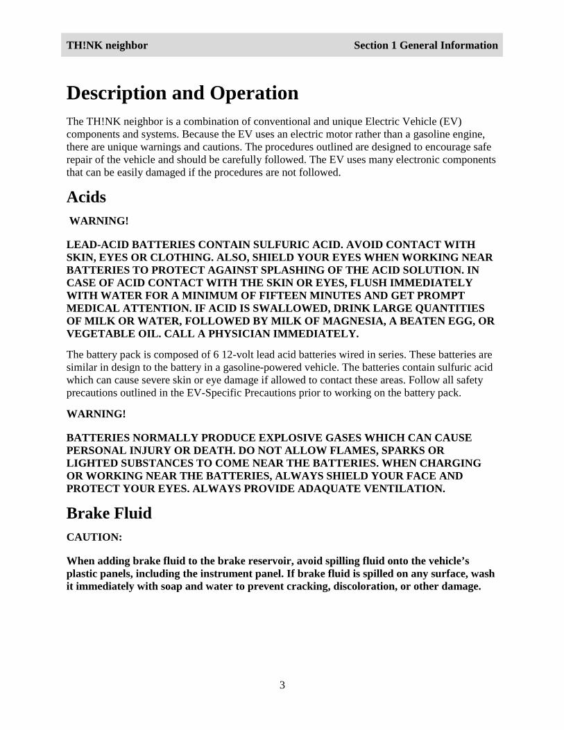
Description and OperationThe TH!NK neighbor is a combination of conventional and unique Electric Vehicle (EV)components and systems. Because the EV uses an electric motor rather than a gasoline engine,there are unique warnings and cautions. The procedures outlined are designed to encourage saferepair of the vehicle and should be carefully followed. The EV uses many electronic componentsthat can be easily damaged if the procedures are not followed.
Acids WARNING!
LEAD-ACID BATTERIES CONTAIN SULFURIC ACID. AVOID CONTACT WITHSKIN, EYES OR CLOTHING. ALSO, SHIELD YOUR EYES WHEN WORKING NEARBATTERIES TO PROTECT AGAINST SPLASHING OF THE ACID SOLUTION. INCASE OF ACID CONTACT WITH THE SKIN OR EYES, FLUSH IMMEDIATELYWITH WATER FOR A MINIMUM OF FIFTEEN MINUTES AND GET PROMPTMEDICAL ATTENTION. IF ACID IS SWALLOWED, DRINK LARGE QUANTITIESOF MILK OR WATER, FOLLOWED BY MILK OF MAGNESIA, A BEATEN EGG, ORVEGETABLE OIL. CALL A PHYSICIAN IMMEDIATELY.
The battery pack is composed of 6 12-volt lead acid batteries wired in series. These batteries aresimilar in design to the battery in a gasoline-powered vehicle. The batteries contain sulfuric acidwhich can cause severe skin or eye damage if allowed to contact these areas. Follow all safetyprecautions outlined in the EV-Specific Precautions prior to working on the battery pack.
WARNING!
BATTERIES NORMALLY PRODUCE EXPLOSIVE GASES WHICH CAN CAUSEPERSONAL INJURY OR DEATH. DO NOT ALLOW FLAMES, SPARKS ORLIGHTED SUBSTANCES TO COME NEAR THE BATTERIES. WHEN CHARGINGOR WORKING NEAR THE BATTERIES, ALWAYS SHIELD YOUR FACE ANDPROTECT YOUR EYES. ALWAYS PROVIDE ADAQUATE VENTILATION.
Brake FluidCAUTION:
When adding brake fluid to the brake reservoir, avoid spilling fluid onto the vehicle’splastic panels, including the instrument panel. If brake fluid is spilled on any surface, washit immediately with soap and water to prevent cracking, discoloration, or other damage.
TH!NK neighbor Section 1 General Information
4
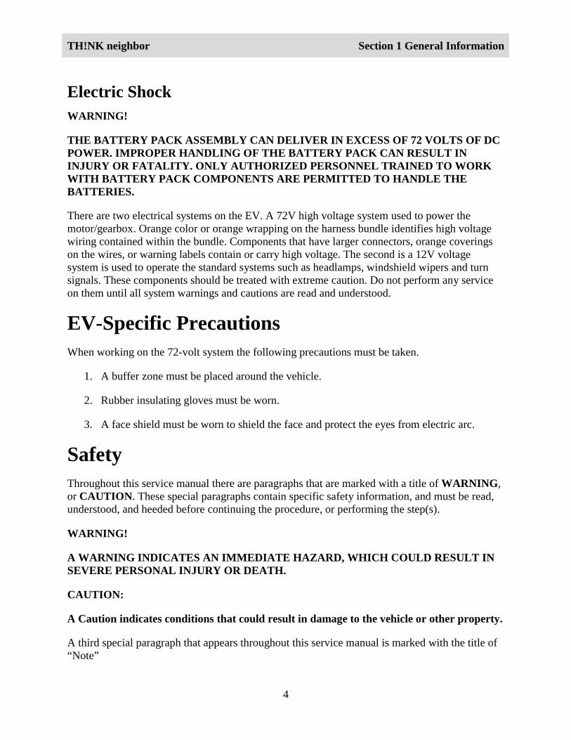
Electric ShockWARNING!
THE BATTERY PACK ASSEMBLY CAN DELIVER IN EXCESS OF 72 VOLTS OF DCPOWER. IMPROPER HANDLING OF THE BATTERY PACK CAN RESULT ININJURY OR FATALITY. ONLY AUTHORIZED PERSONNEL TRAINED TO WORKWITH BATTERY PACK COMPONENTS ARE PERMITTED TO HANDLE THEBATTERIES.
There are two electrical systems on the EV. A 72V high voltage system used to power themotor/gearbox. Orange color or orange wrapping on the harness bundle identifies high voltagewiring contained within the bundle. Components that have larger connectors, orange coveringson the wires, or warning labels contain or carry high voltage. The second is a 12V voltagesystem is used to operate the standard systems such as headlamps, windshield wipers and turnsignals. These components should be treated with extreme caution. Do not perform any serviceon them until all system warnings and cautions are read and understood.
EV-Specific PrecautionsWhen working on the 72-volt system the following precautions must be taken.
1. A buffer zone must be placed around the vehicle.
2. Rubber insulating gloves must be worn.
3. A face shield must be worn to shield the face and protect the eyes from electric arc.
SafetyThroughout this service manual there are paragraphs that are marked with a title of WARNING,or CAUTION. These special paragraphs contain specific safety information, and must be read,understood, and heeded before continuing the procedure, or performing the step(s).
WARNING!
A WARNING INDICATES AN IMMEDIATE HAZARD, WHICH COULD RESULT INSEVERE PERSONAL INJURY OR DEATH.
CAUTION:
A Caution indicates conditions that could result in damage to the vehicle or other property.
A third special paragraph that appears throughout this service manual is marked with the title of“Note”
TH!NK neighbor Section 1 General Information
5
A “Note” is a paragraph that describes essential service or maintenance information that relatesto a particular step(s) or procedure. The “Note” must be read, understood and heeded beforecontinuing with the procedure, or performing the step(s).
Note:
A note contains additional information to make the procedure, or step(s), more easily understoodor implemented. Or it may contain essential maintenance information to assure proper operationof the vehicle.
Rubber Insulating Gloves TestingNote:
The rubber insulating gloves that are to be worn while working on the high voltage system arerated for use on equipment of up to 1000volts. They must be inspected before each use and mustalways be worn in conjunction with the leather outer glove. Any hole in the rubber-insulatingglove is a potential entry point for high voltage.
1. Roll the glove up from the open end until the lower portion of the glove begins to balloonfrom the resulting air pressure. If the glove leaks any air it must not be used.
2. The gloves should not be used if they exhibit any signs of wear and tear.
3. The leather gloves must always be worn over the rubber insulating gloves in order toprotect them.
4. The rubber insulating gloves must be class ”O” and meet all of the American SafetyTesting Materials Standards.
Buffer ZoneNote:
The buffer zone is required only when working on the 72-volt system.
1. Position the vehicle in the service bay.
2. Mark off a 1m (3ft) perimeter around the vehicle.
3. Do not allow any unauthorized personnel into the buffer zone during repairs involving highvoltage. Only personnel trained for service on the high voltage system are to be permitted inthe buffer zone.
TH!NK neighbor Section 1 General Information
6
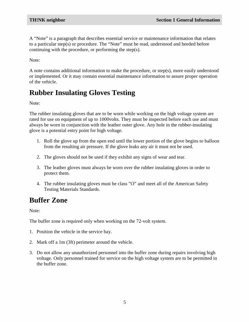
Warning LabelsThe vehicle is equipped with nine different warning labels. These labels are to assist inpreventing the personal injury or death as a result of coming into contact with the high voltagecurrent generated by, or used to operate, the component. The following illustrations show thelocations of the warning labels.
Seat Stanchion Warning Labels
1
22
LGI116_AFrontof Vehicle
Item PartNumber
Description
1 00014 Parking Brake WarningLabel
2 00014 High Voltage WarningLabel
Parking Brake Warning Label
LGI110_A
TH!NK neighbor Section 1 General Information
7
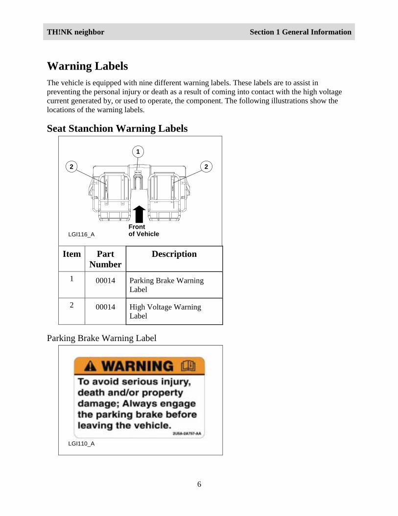
High Voltage Warning Label
LGI111_A
Roof Warning Labels
1 2
LGI117_AFrontof Vehicle
Item PartNumber
Description
1 00014 Slow Moving VehicleWarning
2 00014 High Voltage WarningLabel
TH!NK neighbor Section 1 General Information
8
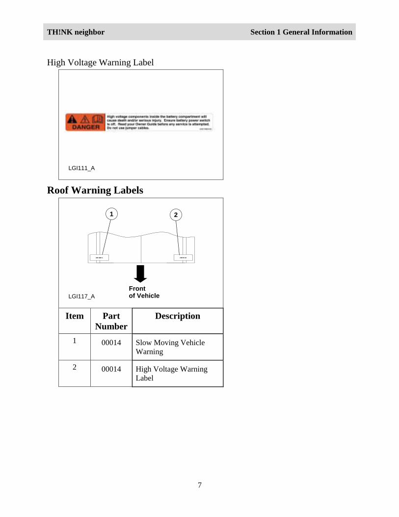
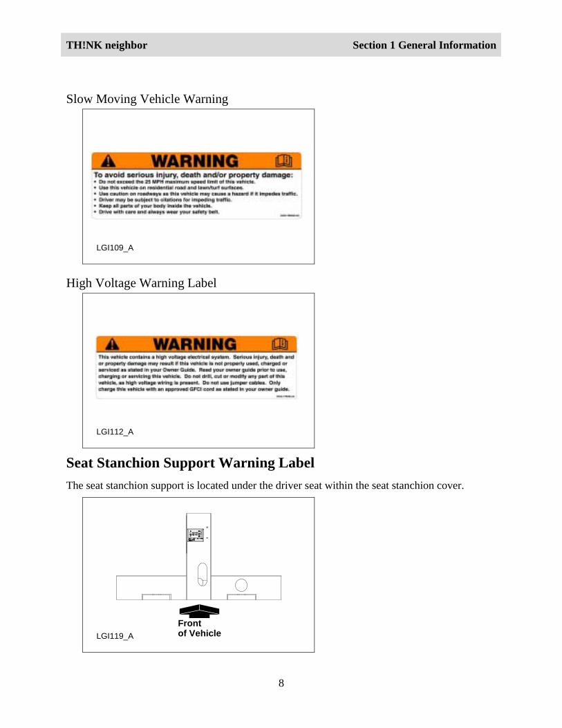
Slow Moving Vehicle Warning
LGI109_A
High Voltage Warning Label
LGI112_A
Seat Stanchion Support Warning LabelThe seat stanchion support is located under the driver seat within the seat stanchion cover.
LGI119_A
Frontof Vehicle
TH!NK neighbor Section 1 General Information
9
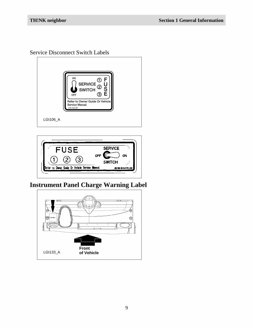
Service Disconnect Switch Labels
LGI106_A
Instrument Panel Charge Warning Label
LGI133_AFrontof Vehicle
TH!NK neighbor Section 1 General Information
10
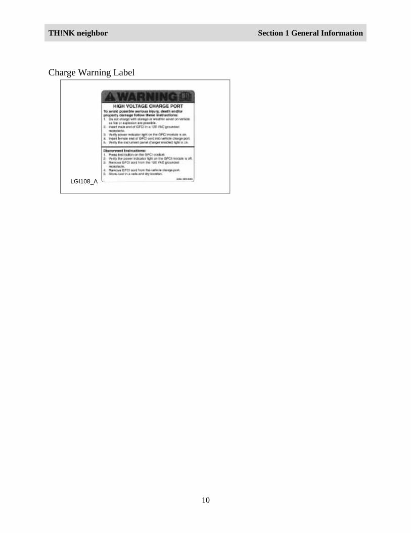
Charge Warning Label
LGI108_A
TH!NK neighbor Section 1 General Information
11
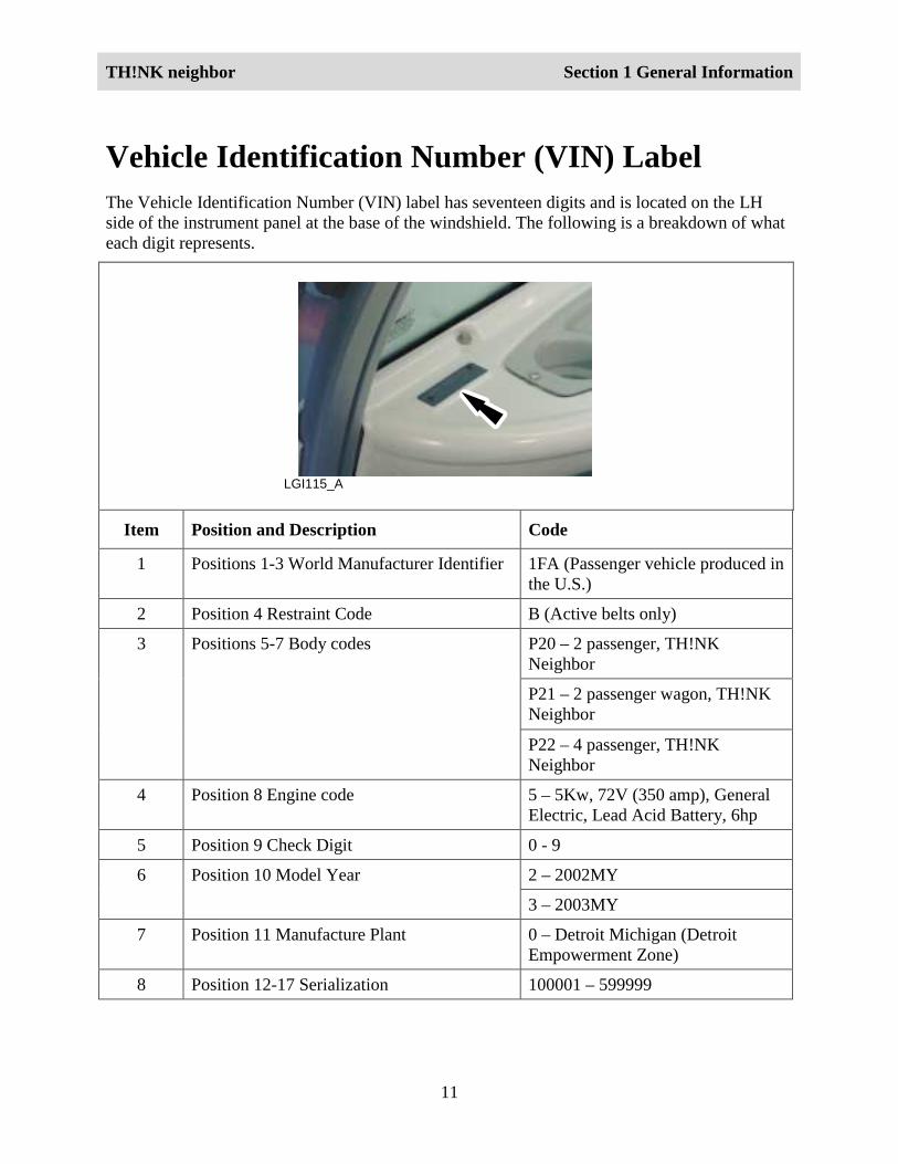
Vehicle Identification Number (VIN) LabelThe Vehicle Identification Number (VIN) label has seventeen digits and is located on the LHside of the instrument panel at the base of the windshield. The following is a breakdown of whateach digit represents.
LGI115_A
Item Position and Description Code
1 Positions 1-3 World Manufacturer Identifier 1FA (Passenger vehicle produced inthe U.S.)
2 Position 4 Restraint Code B (Active belts only)
P20 – 2 passenger, TH!NKNeighbor
P21 – 2 passenger wagon, TH!NKNeighbor
3 Positions 5-7 Body codes
P22 – 4 passenger, TH!NKNeighbor
4 Position 8 Engine code 5 – 5Kw, 72V (350 amp), GeneralElectric, Lead Acid Battery, 6hp
5 Position 9 Check Digit 0 - 9
2 – 2002MY6 Position 10 Model Year
3 – 2003MY
7 Position 11 Manufacture Plant 0 – Detroit Michigan (DetroitEmpowerment Zone)
8 Position 12-17 Serialization 100001 – 599999
TH!NK neighbor Section 1 General Information
12
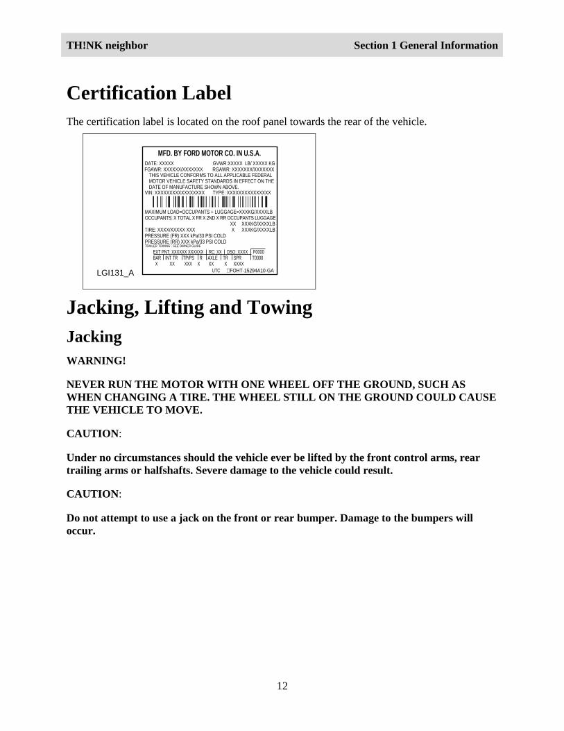
Certification LabelThe certification label is located on the roof panel towards the rear of the vehicle.
LGI131_A
MFD. BY FORD MOTOR CO. IN U.S.A.
EXT PNT: XXXXXX XXXXXX RC: XX DSO: XXXX F0000BAR INT TR TP/PS R AXLE TR SPR T0000 X XX XXX X XX X XXXX
UTC ∇ FOHT-15294A10-GA
MAXIMUM LOAD=OCCUPANTS + LUGGAGE=XXXKG/XXXXLBOCCUPANTS: X TOTAL X FR X 2ND X RR OCCUPANTS LUGGAGE
XX XXXKG/XXXXLBTIRE: XXXX/XXXXX XXX X XXXKG/XXXXLBPRESSURE (FR) XXX kPa/33 PSI COLDPRESSURE (RR) XXX kPa/33 PSI COLDTRAILER TOWING - SEE OWNER GUIDE
DATE: XXXXX GVWR:XXXXX LB/ XXXXX KG
VIN: XXXXXXXXXXXXXXXXX TYPE: XXXXXXXXXXXXXXX
FGAWR: XXXXXX/XXXXXXX RGAWR: XXXXXXX/XXXXXXXTHIS VEHICLE CONFORMS TO ALL APPLICABLE FEDERALMOTOR VEHICLE SAFETY STANDARDS IN EFFECT ON THEDATE OF MANUFACTURE SHOWN ABOVE.
Jacking, Lifting and TowingJackingWARNING!
NEVER RUN THE MOTOR WITH ONE WHEEL OFF THE GROUND, SUCH ASWHEN CHANGING A TIRE. THE WHEEL STILL ON THE GROUND COULD CAUSETHE VEHICLE TO MOVE.
CAUTION:
Under no circumstances should the vehicle ever be lifted by the front control arms, reartrailing arms or halfshafts. Severe damage to the vehicle could result.
CAUTION:
Do not attempt to use a jack on the front or rear bumper. Damage to the bumpers willoccur.
TH!NK neighbor Section 1 General Information
13
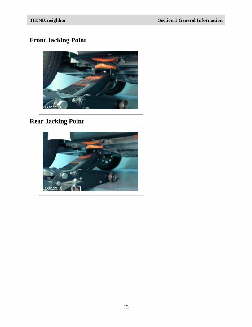
Front Jacking Point
LGI122_A
Rear Jacking Point
LGI123_A
TH!NK neighbor Section 1 General Information
14
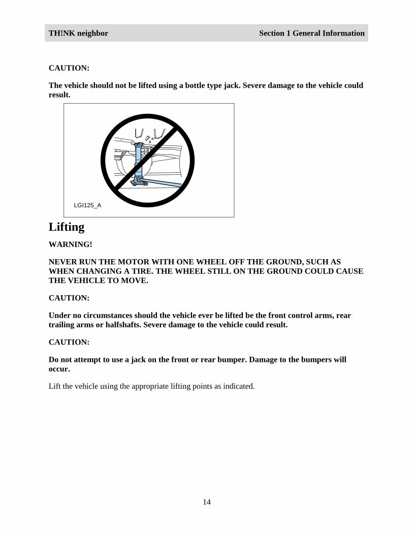
CAUTION:
The vehicle should not be lifted using a bottle type jack. Severe damage to the vehicle couldresult.
LGI125_A
LiftingWARNING!
NEVER RUN THE MOTOR WITH ONE WHEEL OFF THE GROUND, SUCH ASWHEN CHANGING A TIRE. THE WHEEL STILL ON THE GROUND COULD CAUSETHE VEHICLE TO MOVE.
CAUTION:
Under no circumstances should the vehicle ever be lifted be the front control arms, reartrailing arms or halfshafts. Severe damage to the vehicle could result.
CAUTION:
Do not attempt to use a jack on the front or rear bumper. Damage to the bumpers willoccur.
Lift the vehicle using the appropriate lifting points as indicated.
TH!NK neighbor Section 1 General Information
15
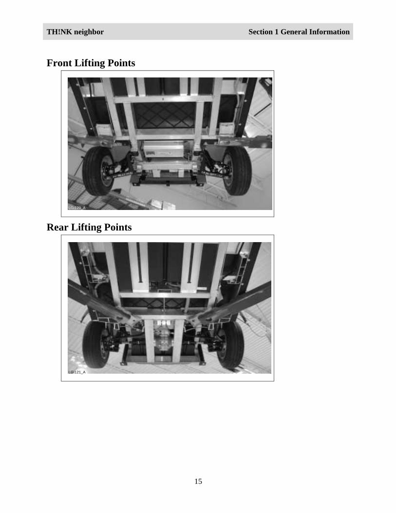
Front Lifting Points
LGI120_A
Rear Lifting Points
LGI121_A
TH!NK neighbor Section 1 General Information
16
CAUTION:
The vehicle should not be lifted using a bottle type jack. Severe damage to the vehicle couldresult.
LGI125_A
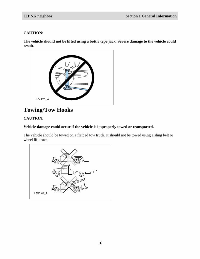
Towing/Tow HooksCAUTION:
Vehicle damage could occur if the vehicle is improperly towed or transported.
The vehicle should be towed on a flatbed tow truck. It should not be towed using a sling belt orwheel lift truck.
LGI126_A
TH!NK neighbor Section 1 General Information
17
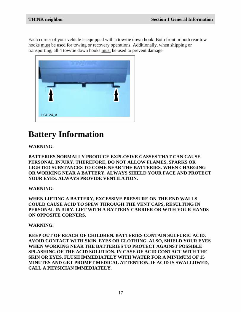
Each corner of your vehicle is equipped with a tow/tie down hook. Both front or both rear towhooks must be used for towing or recovery operations. Additionally, when shipping ortransporting, all 4 tow/tie down hooks must be used to prevent damage.
LGI124_A
Battery InformationWARNING:
BATTERIES NORMALLY PRODUCE EXPLOSIVE GASSES THAT CAN CAUSEPERSONAL INJURY. THEREFORE, DO NOT ALLOW FLAMES, SPARKS ORLIGHTED SUBSTANCES TO COME NEAR THE BATTERIES. WHEN CHARGINGOR WORKING NEAR A BATTERY, ALWAYS SHIELD YOUR FACE AND PROTECTYOUR EYES. ALWAYS PROVIDE VENTILATION.
WARNING:
WHEN LIFTING A BATTERY, EXCESSIVE PRESSURE ON THE END WALLSCOULD CAUSE ACID TO SPEW THROUGH THE VENT CAPS, RESULTING INPERSONAL INJURY. LIFT WITH A BATTERY CARRIER OR WITH YOUR HANDSON OPPOSITE CORNERS.
WARNING:
KEEP OUT OF REACH OF CHILDREN. BATTERIES CONTAIN SULFURIC ACID.AVOID CONTACT WITH SKIN, EYES OR CLOTHING. ALSO, SHIELD YOUR EYESWHEN WORKING NEAR THE BATTERIES TO PROTECT AGAINST POSSIBLESPLASHING OF THE ACID SOLUTION. IN CASE OF ACID CONTACT WITH THESKIN OR EYES, FLUSH IMMEDIATELY WITH WATER FOR A MINIMUM OF 15MINUTES AND GET PROMPT MEDICAL ATTENTION. IF ACID IS SWALLOWED,CALL A PHYSICIAN IMMEDIATELY.
TH!NK neighbor Section 1 General Information
18
WARNING!
THE BATTERY PACK ASSEMBLY CAN DELIVER IN EXCESS OF 72 VOLTS OF DCPOWER. IMPROPER HANDLING OF THE BATTERY PACK CAN RESULT ININJURY OR FATALITY. ONLY AUTHORIZED PERSONNEL TRAINED TO WORKWITH BATTERY PACK COMPONENTS ARE PERMITTED TO HANDLE THEBATTERIES.
LGI132_A
LE
AD
RE
TU
RN
RECYCLE
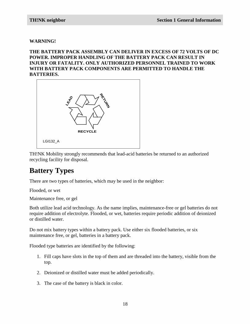
TH!NK Mobility strongly recommends that lead-acid batteries be returned to an authorizedrecycling facility for disposal.
Battery TypesThere are two types of batteries, which may be used in the neighbor:
Flooded, or wet
Maintenance free, or gel
Both utilize lead acid technology. As the name implies, maintenance-free or gel batteries do notrequire addition of electrolyte. Flooded, or wet, batteries require periodic addition of deionizedor distilled water.
Do not mix battery types within a battery pack. Use either six flooded batteries, or sixmaintenance free, or gel, batteries in a battery pack.
Flooded type batteries are identified by the following:
1. Fill caps have slots in the top of them and are threaded into the battery, visible from thetop.
2. Deionized or distilled water must be added periodically.
3. The case of the battery is black in color.
TH!NK neighbor Section 1 General Information
19
4. There is no carrying handle built in to aid in removal and installation.
5. Part number 10655-AA
Maintenance Free (Gel type) batteries are identified by the following:
1. Fill caps are a hexagonal shape and are permanently installed. They are not intended to beremoved and non-serviceable. DO NOT OPEN
2. The case of the battery is gray in color.
3. There is a handle built in to aid in removal and installation.
4. Part number 10655-BA
Battery Fill Procedure – Flooded Batteries OnlyNote:
Be sure you have correctly identified the type of battery installed in the vehicle. Do not addelectrolyte to maintenance-free, or gel, batteries. For additional information, refer to BatteryTypes in this section.
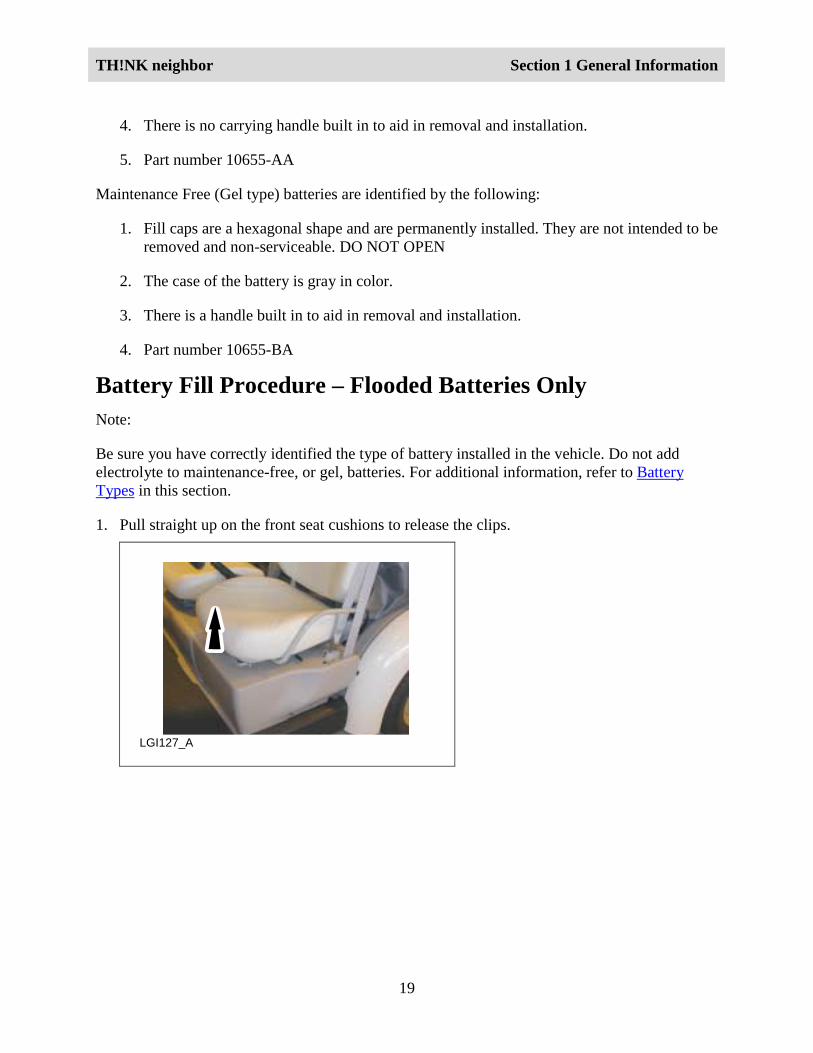
1. Pull straight up on the front seat cushions to release the clips.
LGI127_A
TH!NK neighbor Section 1 General Information
20
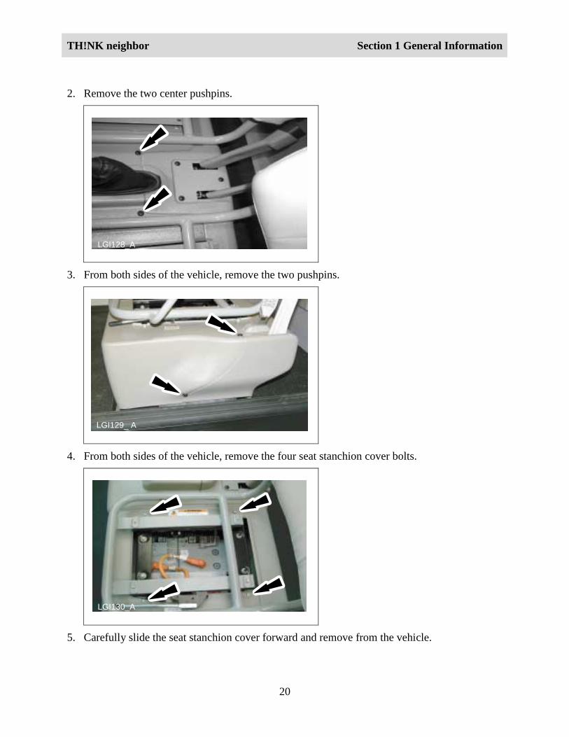
2. Remove the two center pushpins.
LGI128_A
3. From both sides of the vehicle, remove the two pushpins.
LGI129_ A
4. From both sides of the vehicle, remove the four seat stanchion cover bolts.
LGI130_A
5. Carefully slide the seat stanchion cover forward and remove from the vehicle.
TH!NK neighbor Section 1 General Information
21
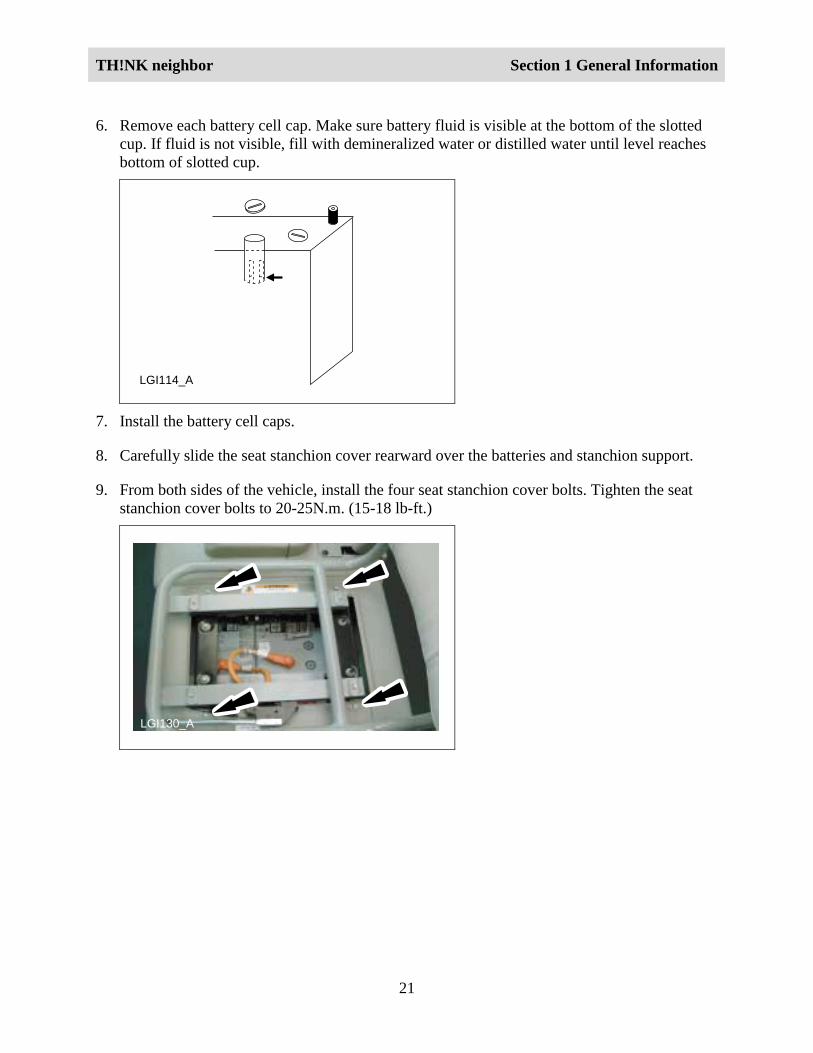
6. Remove each battery cell cap. Make sure battery fluid is visible at the bottom of the slottedcup. If fluid is not visible, fill with demineralized water or distilled water until level reachesbottom of slotted cup.
LGI114_A
7. Install the battery cell caps.
8. Carefully slide the seat stanchion cover rearward over the batteries and stanchion support.
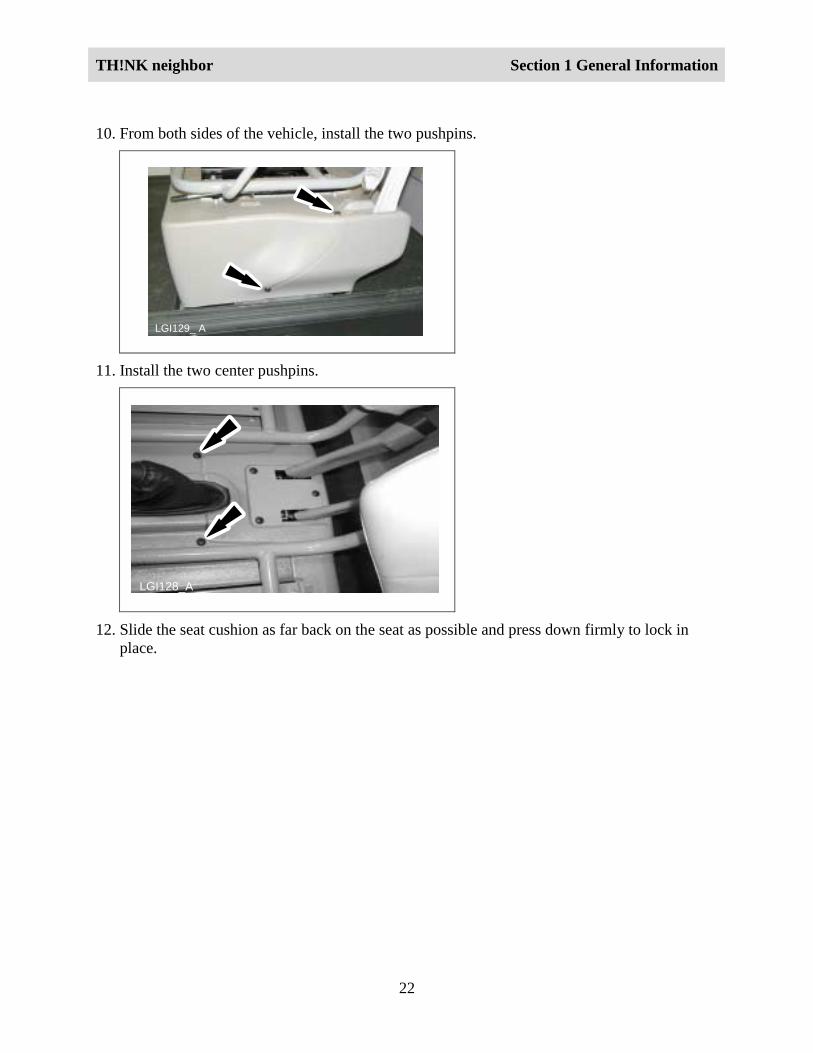
9. From both sides of the vehicle, install the four seat stanchion cover bolts. Tighten the seatstanchion cover bolts to 20-25N.m. (15-18 lb-ft.)
LGI130_A
TH!NK neighbor Section 1 General Information
22
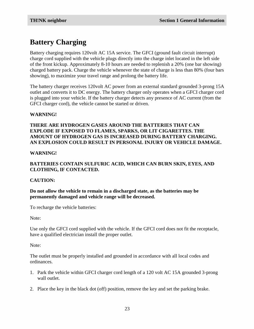
10. From both sides of the vehicle, install the two pushpins.
LGI129_ A
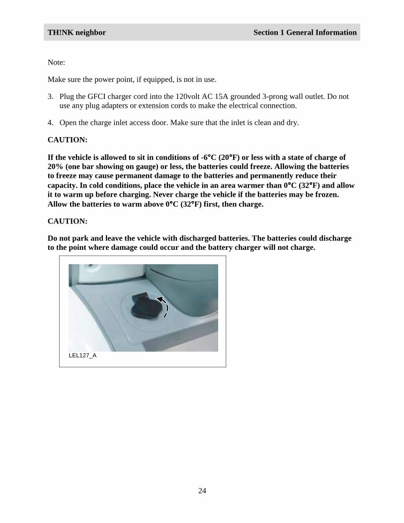
11. Install the two center pushpins.
LGI128_A
12. Slide the seat cushion as far back on the seat as possible and press down firmly to lock inplace.
TH!NK neighbor Section 1 General Information
23
Battery ChargingBattery charging requires 120volt AC 15A service. The GFCI (ground fault circuit interrupt)charge cord supplied with the vehicle plugs directly into the charge inlet located in the left sideof the front kickup. Approximately 8-10 hours are needed to replenish a 20% (one bar showing)charged battery pack. Charge the vehicle whenever the state of charge is less than 80% (four barsshowing), to maximize your travel range and prolong the battery life.
The battery charger receives 120volt AC power from an external standard grounded 3-prong 15Aoutlet and converts it to DC energy. The battery charger only operates when a GFCI charger cordis plugged into your vehicle. If the battery charger detects any presence of AC current (from theGFCI charger cord), the vehicle cannot be started or driven.
WARNING!
THERE ARE HYDROGEN GASES AROUND THE BATTERIES THAT CANEXPLODE IF EXPOSED TO FLAMES, SPARKS, OR LIT CIGARETTES. THEAMOUNT OF HYDROGEN GAS IS INCREASED DURING BATTERY CHARGING.AN EXPLOSION COULD RESULT IN PERSONAL INJURY OR VEHICLE DAMAGE.
WARNING!
BATTERIES CONTAIN SULFURIC ACID, WHICH CAN BURN SKIN, EYES, ANDCLOTHING, IF CONTACTED.
CAUTION:
Do not allow the vehicle to remain in a discharged state, as the batteries may bepermanently damaged and vehicle range will be decreased.
To recharge the vehicle batteries:
Note:
Use only the GFCI cord supplied with the vehicle. If the GFCI cord does not fit the receptacle,have a qualified electrician install the proper outlet.
Note:
The outlet must be properly installed and grounded in accordance with all local codes andordinances.
1. Park the vehicle within GFCI charger cord length of a 120 volt AC 15A grounded 3-prongwall outlet.
2. Place the key in the black dot (off) position, remove the key and set the parking brake.
TH!NK neighbor Section 1 General Information
24
Note:
Make sure the power point, if equipped, is not in use.
3. Plug the GFCI charger cord into the 120volt AC 15A grounded 3-prong wall outlet. Do notuse any plug adapters or extension cords to make the electrical connection.
4. Open the charge inlet access door. Make sure that the inlet is clean and dry.
CAUTION:
If the vehicle is allowed to sit in conditions of -6°°°°C (20°°°°F) or less with a state of charge of20% (one bar showing on gauge) or less, the batteries could freeze. Allowing the batteriesto freeze may cause permanent damage to the batteries and permanently reduce theircapacity. In cold conditions, place the vehicle in an area warmer than 0°°°°C (32°°°°F) and allowit to warm up before charging. Never charge the vehicle if the batteries may be frozen.Allow the batteries to warm above 0°°°°C (32°°°°F) first, then charge.
CAUTION:
Do not park and leave the vehicle with discharged batteries. The batteries could dischargeto the point where damage could occur and the battery charger will not charge.
LEL127_A
TH!NK neighbor Section 1 General Information
25
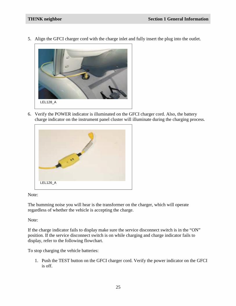
5. Align the GFCI charger cord with the charge inlet and fully insert the plug into the outlet.
LEL128_A
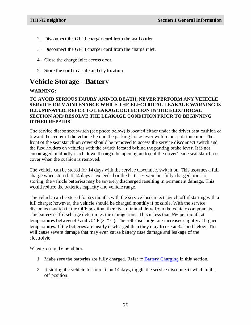
6. Verify the POWER indicator is illuminated on the GFCI charger cord. Also, the batterycharge indicator on the instrument panel cluster will illuminate during the charging process.
LEL126_A
Note:
The humming noise you will hear is the transformer on the charger, which will operateregardless of whether the vehicle is accepting the charge.
Note:
If the charge indicator fails to display make sure the service disconnect switch is in the “ON”position. If the service disconnect switch is on while charging and charge indicator fails todisplay, refer to the following flowchart.
To stop charging the vehicle batteries:
1. Push the TEST button on the GFCI charger cord. Verify the power indicator on the GFCIis off.
TH!NK neighbor Section 1 General Information
26
2. Disconnect the GFCI charger cord from the wall outlet.
3. Disconnect the GFCI charger cord from the charge inlet.
4. Close the charge inlet access door.
5. Store the cord in a safe and dry location.
Vehicle Storage - BatteryWARNING:TO AVOID SERIOUS INJURY AND/OR DEATH, NEVER PERFORM ANY VEHICLESERVICE OR MAINTENANCE WHILE THE ELECTRICAL LEAKAGE WARNING ISILLUMINATED. REFER TO LEAKAGE DETECTION IN THE ELECTRICALSECTION AND RESOLVE THE LEAKAGE CONDITION PRIOR TO BEGINNINGOTHER REPAIRS.
The service disconnect switch (see photo below) is located either under the driver seat cushion ortoward the center of the vehicle behind the parking brake lever within the seat stanchion. Thefront of the seat stanchion cover should be removed to access the service disconnect switch andthe fuse holders on vehicles with the switch located behind the parking brake lever. It is notencouraged to blindly reach down through the opening on top of the driver's side seat stanchioncover when the cushion is removed.
The vehicle can be stored for 14 days with the service disconnect switch on. This assumes a fullcharge when stored. If 14 days is exceeded or the batteries were not fully charged prior tostoring, the vehicle batteries may be severely discharged resulting in permanent damage. Thiswould reduce the batteries capacity and vehicle range.
The vehicle can be stored for six months with the service disconnect switch off if starting with afull charge; however, the vehicle should be charged monthly if possible. With the servicedisconnect switch in the OFF position, there is a minimal draw from the vehicle components.The battery self-discharge determines the storage time. This is less than 5% per month attemperatures between 40 and 70° F (21° C). The self-discharge rate increases slightly at highertemperatures. If the batteries are nearly discharged then they may freeze at 32° and below. Thiswill cause severe damage that may even cause battery case damage and leakage of theelectrolyte.
When storing the neighbor:
1. Make sure the batteries are fully charged. Refer to Battery Charging in this section.
2. If storing the vehicle for more than 14 days, toggle the service disconnect switch to theoff position.
TH!NK neighbor Section 1 General Information
27
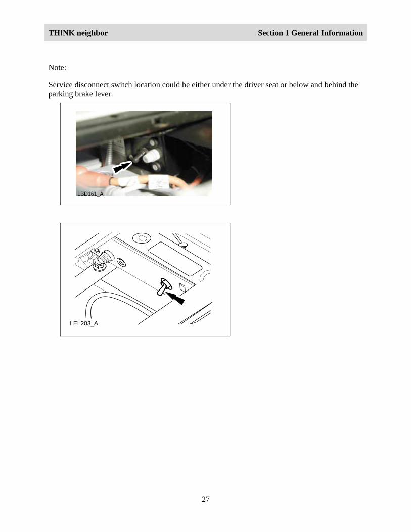
Note:
Service disconnect switch location could be either under the driver seat or below and behind theparking brake lever.
LBD161_A
LEL203_A
TH!NK neighbor Section 1 General Information
28
Battery Water Reminder Indicator Resetting (FloodedBatteries Only)Caution:
If the vehicle is equipped with flooded batteries, the instrument cluster gauge must beprogrammed for flooded batteries. Damage to the batteries can occur if the battery type isincorrectly programmed. Refer to Battery Type Reprogramming in this section.
Note:
The battery water reminder function of the instrument cluster gauge must be reset whenever thebattery water has been checked and filled. The indicator will illuminate every 300miles(483kms). Battery electrolyte levels should be checked every 300 miles (483kms) or monthly,whichever comes first. The only time the battery water indicator can be reset is when the key isin the R (Reverse) position, the instrument cluster gauge is in the flooded battery mode and thebattery water reminder indicator is on.
1. Turn the key to R (Reverse) position.
2. Press and hold the Select/Reset button for over 3 seconds.
3. Turn the key to the OFF (black dot) position.
Battery Type ReprogrammingCAUTION:
If the type of battery (flooded to gel, gel to flooded) is being changed, the instrument clustergauge must reprogrammed to avoid battery pack damage. The charging rate differsbetween type of battery and the battery water reminder indicator must be turned on forflooded type batteries.
1. With the key in the OFF (black dot) position, press and hold down the Select/Resetbutton.
2. Turn the key to the D (Drive) position.
3. Release the Select/Reset button.
4. Turn the key to the R (Reverse) position.
5. Press and release the Select/Reset button to alternate between the flooded and sealedbattery modes.
TH!NK neighbor Section 1 General Information
29
6. Turn the key to the OFF (black dot) position. The gauge will automatically exit thereprogramming mode after 10 seconds.
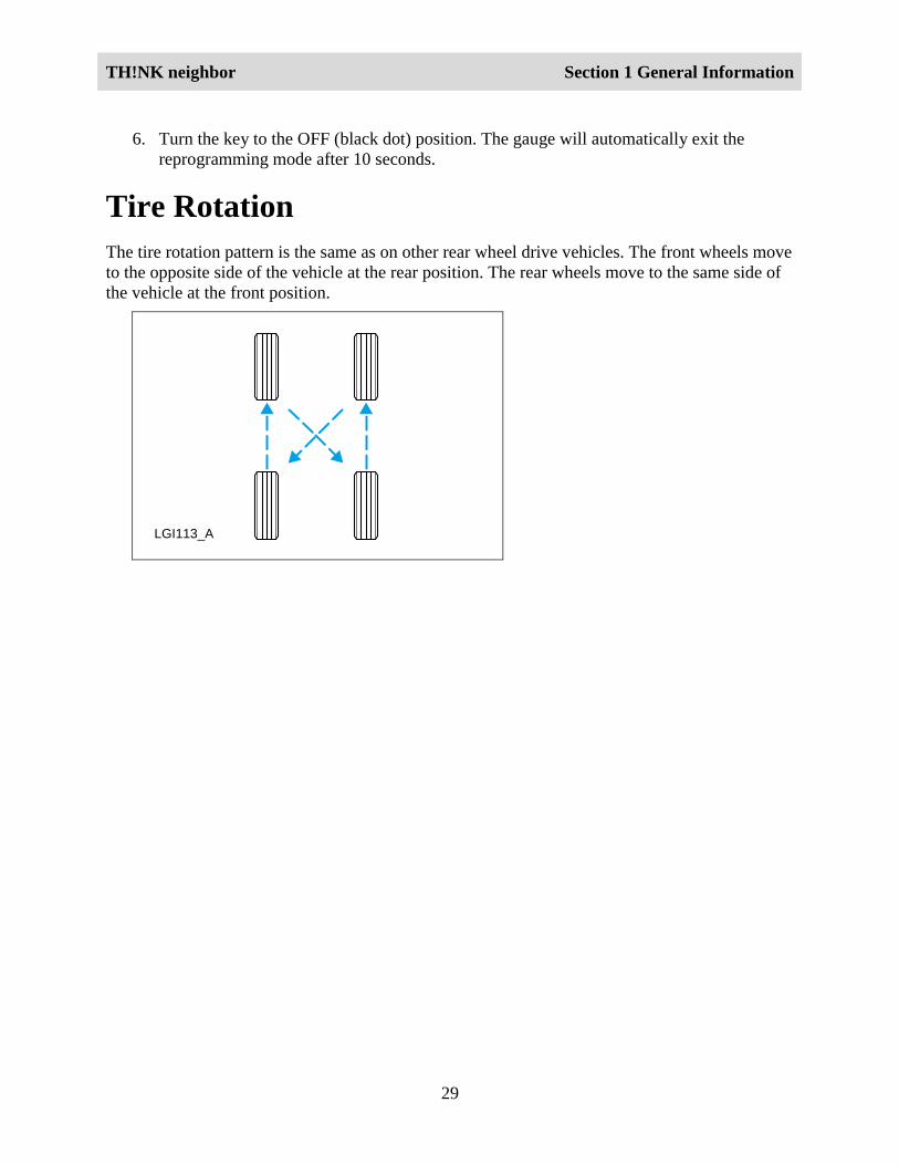
Tire RotationThe tire rotation pattern is the same as on other rear wheel drive vehicles. The front wheels moveto the opposite side of the vehicle at the rear position. The rear wheels move to the same side ofthe vehicle at the front position.
LGI113_A
TH!NK neighbor Section 1 General Information
30
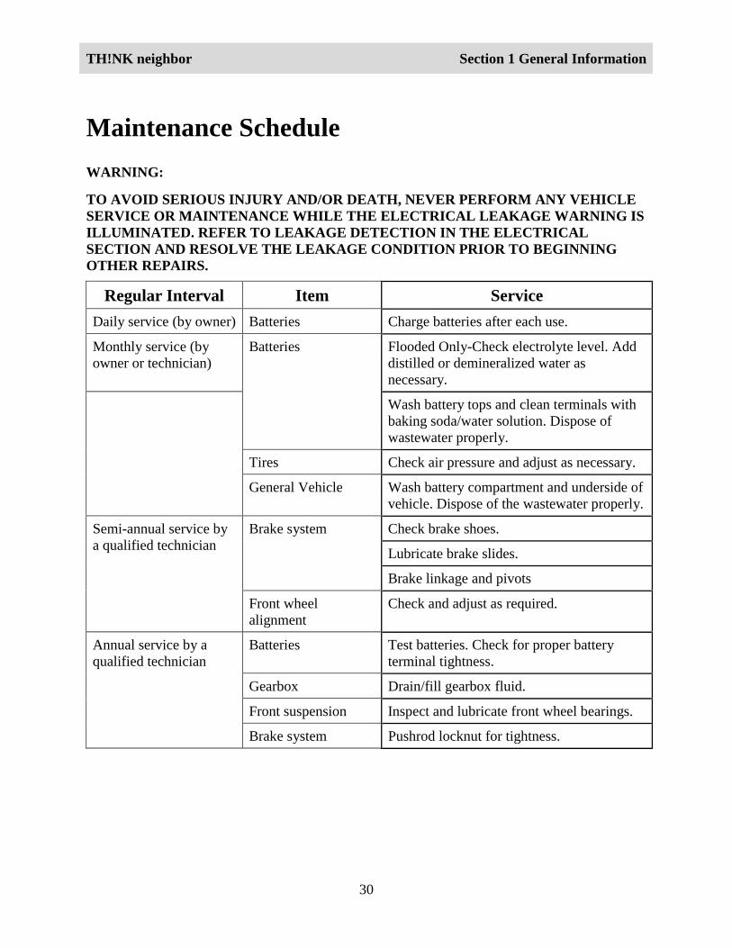
Maintenance ScheduleWARNING:
TO AVOID SERIOUS INJURY AND/OR DEATH, NEVER PERFORM ANY VEHICLESERVICE OR MAINTENANCE WHILE THE ELECTRICAL LEAKAGE WARNING ISILLUMINATED. REFER TO LEAKAGE DETECTION IN THE ELECTRICALSECTION AND RESOLVE THE LEAKAGE CONDITION PRIOR TO BEGINNINGOTHER REPAIRS.
Regular Interval Item ServiceDaily service (by owner) Batteries Charge batteries after each use.
Monthly service (byowner or technician)
Flooded Only-Check electrolyte level. Adddistilled or demineralized water asnecessary.
Batteries
Wash battery tops and clean terminals withbaking soda/water solution. Dispose ofwastewater properly.
Tires Check air pressure and adjust as necessary.
General Vehicle Wash battery compartment and underside ofvehicle. Dispose of the wastewater properly.
Check brake shoes.
Lubricate brake slides.
Brake system
Brake linkage and pivots
Semi-annual service bya qualified technician
Front wheelalignment
Check and adjust as required.
Batteries Test batteries. Check for proper batteryterminal tightness.
Gearbox Drain/fill gearbox fluid.
Front suspension Inspect and lubricate front wheel bearings.
Annual service by aqualified technician
Brake system Pushrod locknut for tightness.