Embed Size (px)
Citation preview
Section 13: PLATE BENDING ELEMENTS
Washkewicz College of Engineering
Plate Theory
A plate is a structural element whose mid surface lies in a flat plane. The dimension in the direction normal to the plane is referred to as the thickness of the plate. A plate is characterized by a small thickness relative to the other dimensions of the plate.
Plates may be classified by the relative thickness of the structural element. We can speak of:
1. Relatively thick plates with small displacements
2. Relatively thin plates with small displacements
3. Very thin plates with large deflections
4. Extremely thin plates (membranes) with large or small deflections
If a plate is curved as opposed to flat, we refer to these structural elements as shells. We start the discussion with classical thin plate theory attributed to Kirchoff
1
Section 13: PLATE BENDING ELEMENTS
Washkewicz College of Engineering
Plate Geometry and Deformation
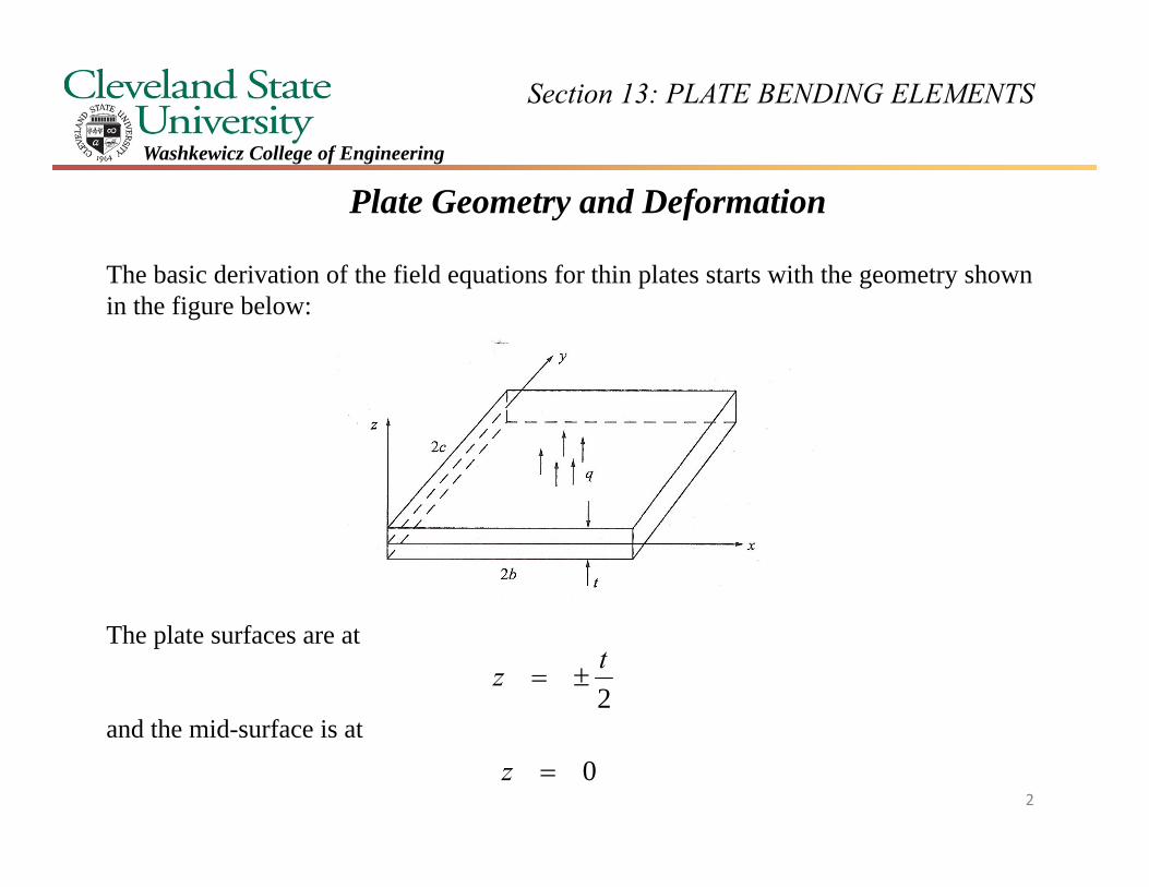
The basic derivation of the field equations for thin plates starts with the geometry shown in the figure below:
The plate surfaces are at
and the mid-surface is at0z
2tz
2
Section 13: PLATE BENDING ELEMENTS
Washkewicz College of Engineering
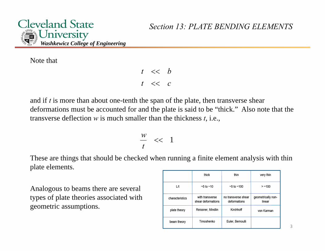
Note that
and if t is more than about one-tenth the span of the plate, then transverse shear deformations must be accounted for and the plate is said to be “thick.” Also note that the transverse deflection w is much smaller than the thickness t, i.e.,
These are things that should be checked when running a finite element analysis with thin plate elements.
ctbt
1tw
Analogous to beams there are several types of plate theories associated with geometric assumptions.
3
Section 13: PLATE BENDING ELEMENTS
Washkewicz College of Engineering
Kirchhoff Assumptions and Theoretical Formulation
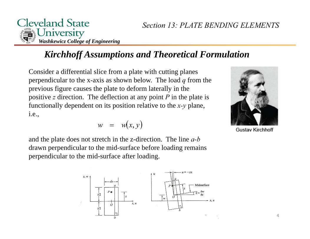
Consider a differential slice from a plate with cutting planes perpendicular to the x-axis as shown below. The load q from the previous figure causes the plate to deform laterally in the positive z direction. The deflection at any point P in the plate is functionally dependent on its position relative to the x-y plane, i.e.,
and the plate does not stretch in the z-direction. The line a-b drawn perpendicular to the mid-surface before loading remains perpendicular to the mid-surface after loading.
yxww ,
4
Section 13: PLATE BENDING ELEMENTS
Washkewicz College of Engineering
This is consistent with the Kirchoff assumptions which are stated as follows:
1. Straight lines normal to the mid surface remain normal. This implies that
However
that is right angles in the plane of the plate do not necessarily remain right angles after the plate is loaded.
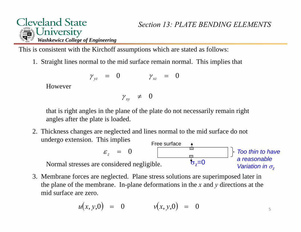
2. Thickness changes are neglected and lines normal to the mid surface do not undergo extension. This implies
Normal stresses are considered negligible.
3. Membrane forces are neglected. Plane stress solutions are superimposed later in the plane of the membrane. In-plane deformations in the x and y directions at the mid surface are zero.
00 xzyz
0xy
0z
00,,00,, yxvyxu
z=0
Free surfaceToo thin to have a reasonable Variation in z
5
Section 13: PLATE BENDING ELEMENTS
Washkewicz College of Engineering
xz
xz
zx
zx
x
zy
xz
xz
zx
zx
x
zy
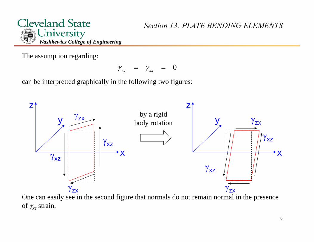
The assumption regarding:
can be interpretted graphically in the following two figures:
One can easily see in the second figure that normals do not remain normal in the presence of xz strain.
0 zxxz
by a rigid body rotation
6
Section 13: PLATE BENDING ELEMENTS
Washkewicz College of Engineering
zy
yz
yz
zy
z y
x
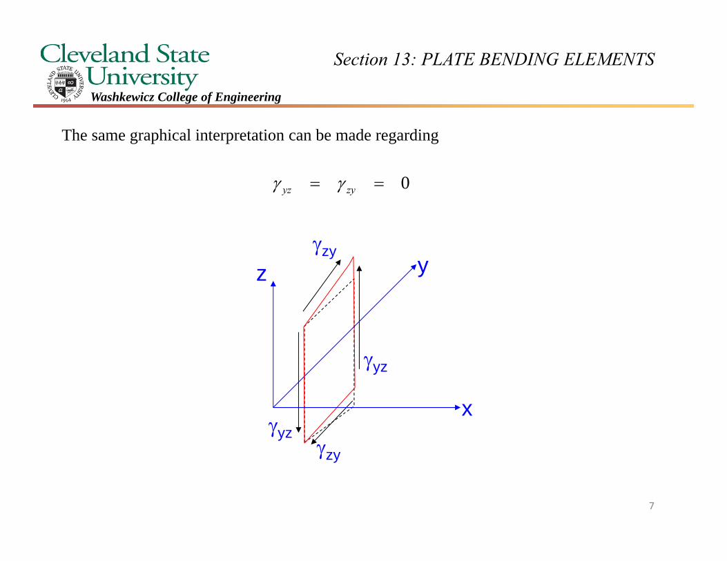
The same graphical interpretation can be made regarding
0 zyyz
7
Section 13: PLATE BENDING ELEMENTS
Washkewicz College of Engineering
z
x yzzyxu ,,
xw
y
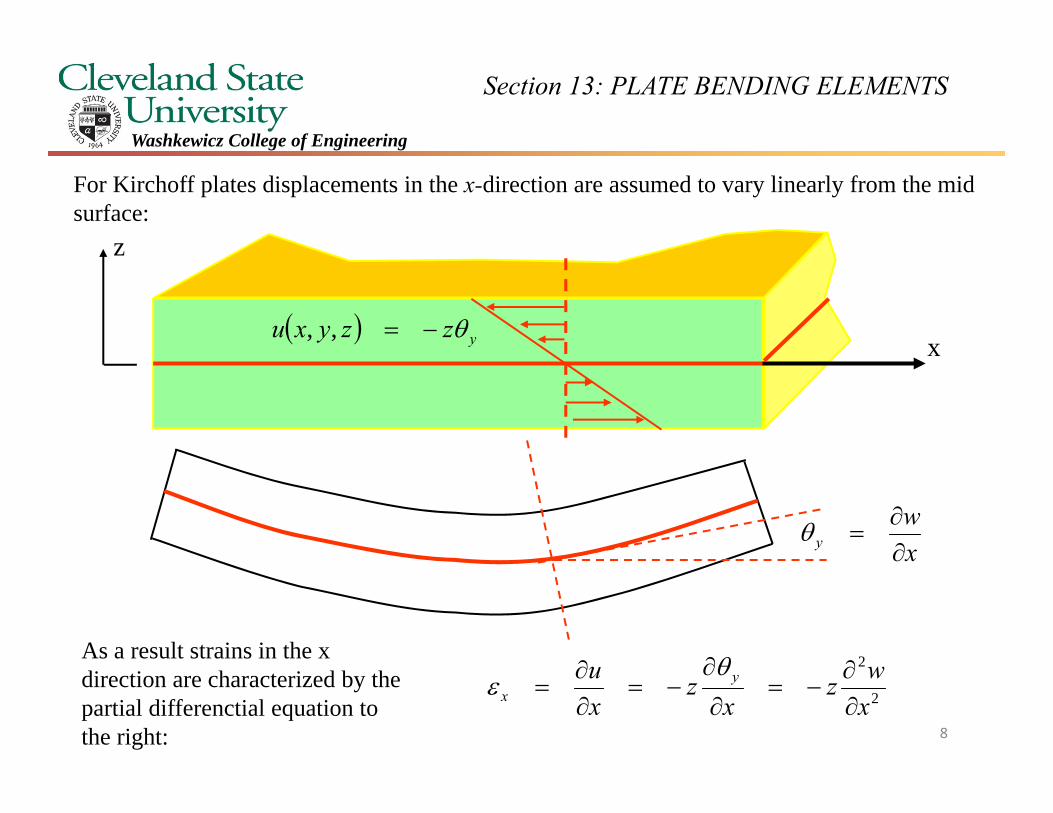
For Kirchoff plates displacements in the x-direction are assumed to vary linearly from the mid surface:
As a result strains in the x direction are characterized by the partial differenctial equation to the right:
2
2
xwz
xz
xu y
x
8
Section 13: PLATE BENDING ELEMENTS
Washkewicz College of Engineering
xzzyxv ,,
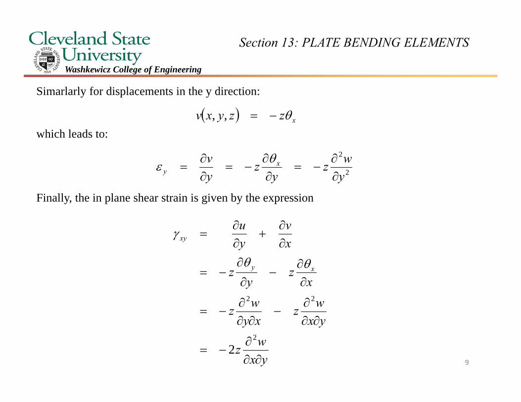
Simarlarly for displacements in the y direction:
which leads to:
Finally, the in plane shear strain is given by the expression
2
2
ywz
yz
yv x
y
yxwz
yxwz
xywz
xz
yz
xv
yu
xy
xy
2
22
2
9
Section 13: PLATE BENDING ELEMENTS
Washkewicz College of Engineering
yxw
yw
xw
xy
y
x
2
2
2
2
2
2
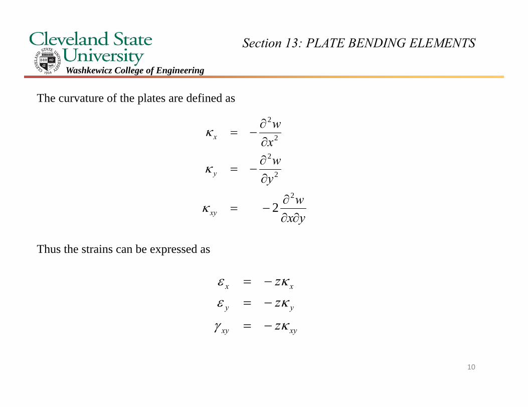
The curvature of the plates are defined as
Thus the strains can be expressed as
xyxy
yy
xx
z
zz
10
Section 13: PLATE BENDING ELEMENTS
Washkewicz College of Engineering
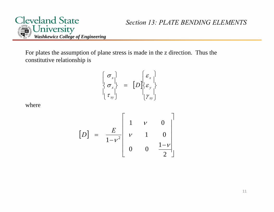
For plates the assumption of plane stress is made in the z direction. Thus the constitutive relationship is
where
xy
y
x
xy
x
x
D
2100
01
01
1 2
ED
11
Section 13: PLATE BENDING ELEMENTS
Washkewicz College of Engineering
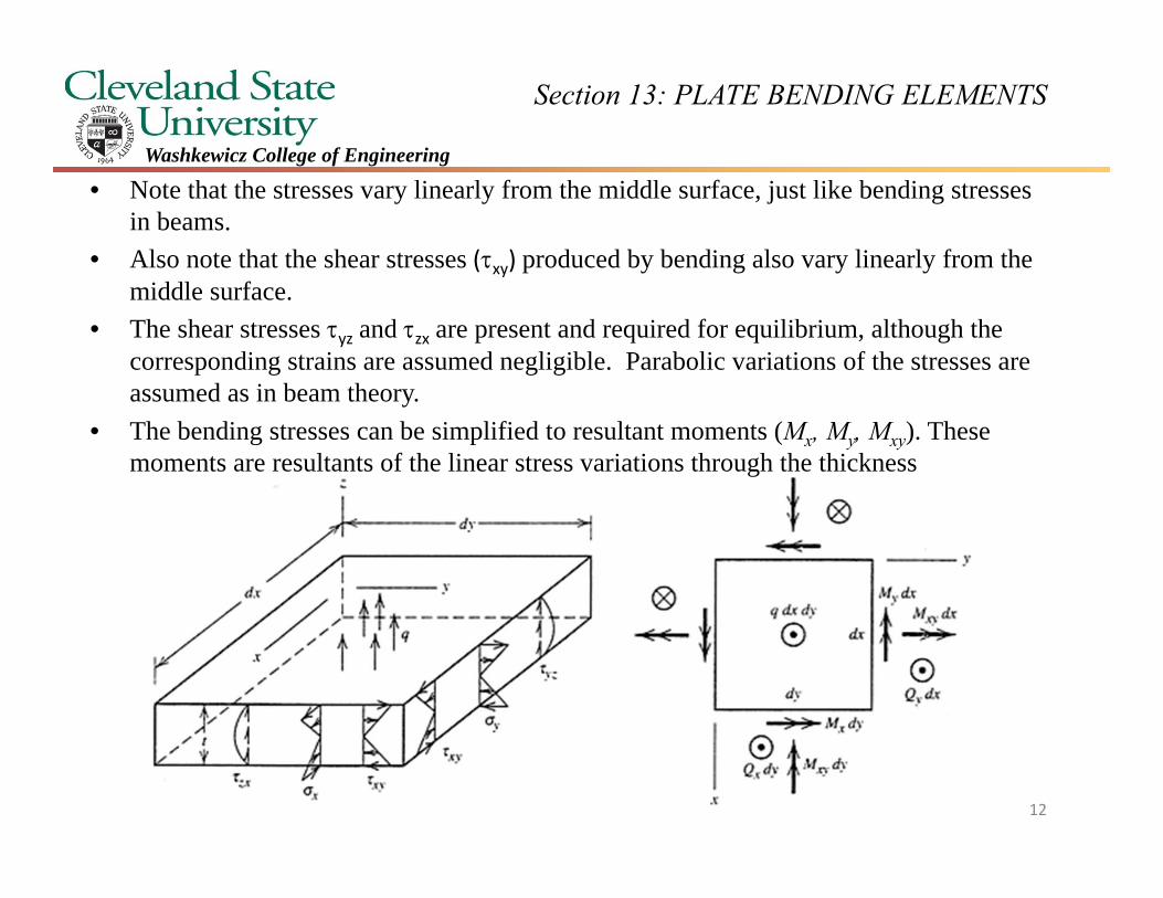
• Note that the stresses vary linearly from the middle surface, just like bending stresses in beams.
• Also note that the shear stresses (xy) produced by bending also vary linearly from the middle surface.
• The shear stresses yz and zx are present and required for equilibrium, although the corresponding strains are assumed negligible. Parabolic variations of the stresses are assumed as in beam theory.
• The bending stresses can be simplified to resultant moments (Mx, My, Mxy). These moments are resultants of the linear stress variations through the thickness
12
Section 13: PLATE BENDING ELEMENTS
Washkewicz College of Engineering
x
zy
MxydyMxdy
Qxdy
QydxMyxdx
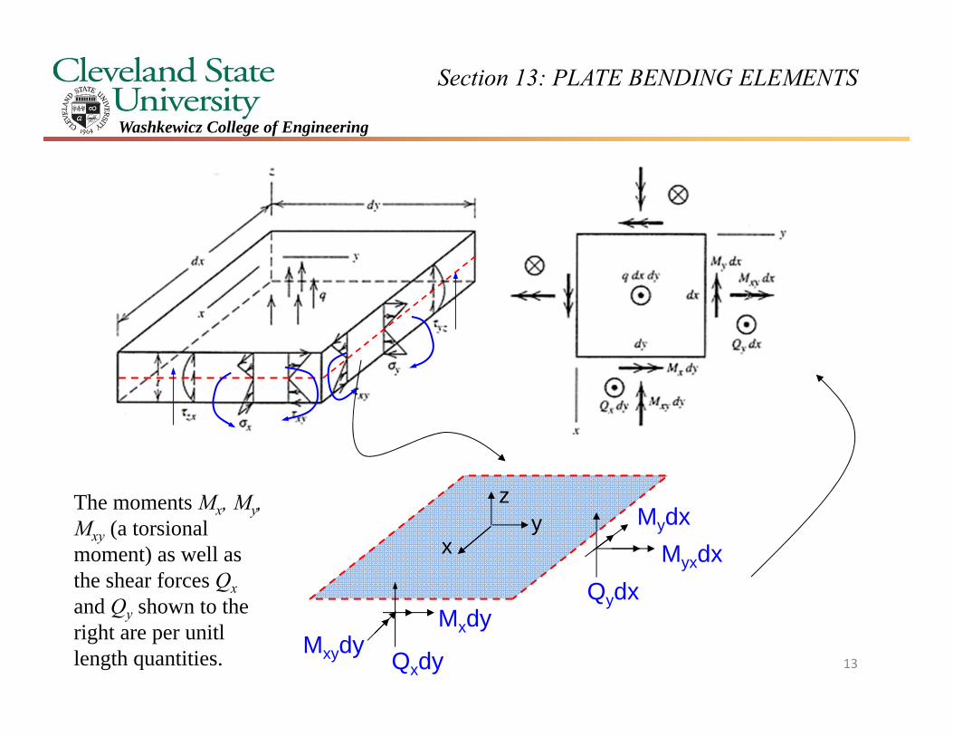
MydxThe moments Mx, My, Mxy (a torsional moment) as well as the shear forces Qxand Qy shown to the right are per unitl length quantities. 13
Section 13: PLATE BENDING ELEMENTS
Washkewicz College of Engineering
xy
y
x
xy
y
x
z
yxw
yw
xw
z
2
2
2
2
2
2
xy
y
x
xy
y
x
xy
y
x EzE
10001
01
1100
01
01
1 22
next page
2
2
t
txy
y
x
xy
y
x
zdz
dy
dxdy
dyM
dxMdyM
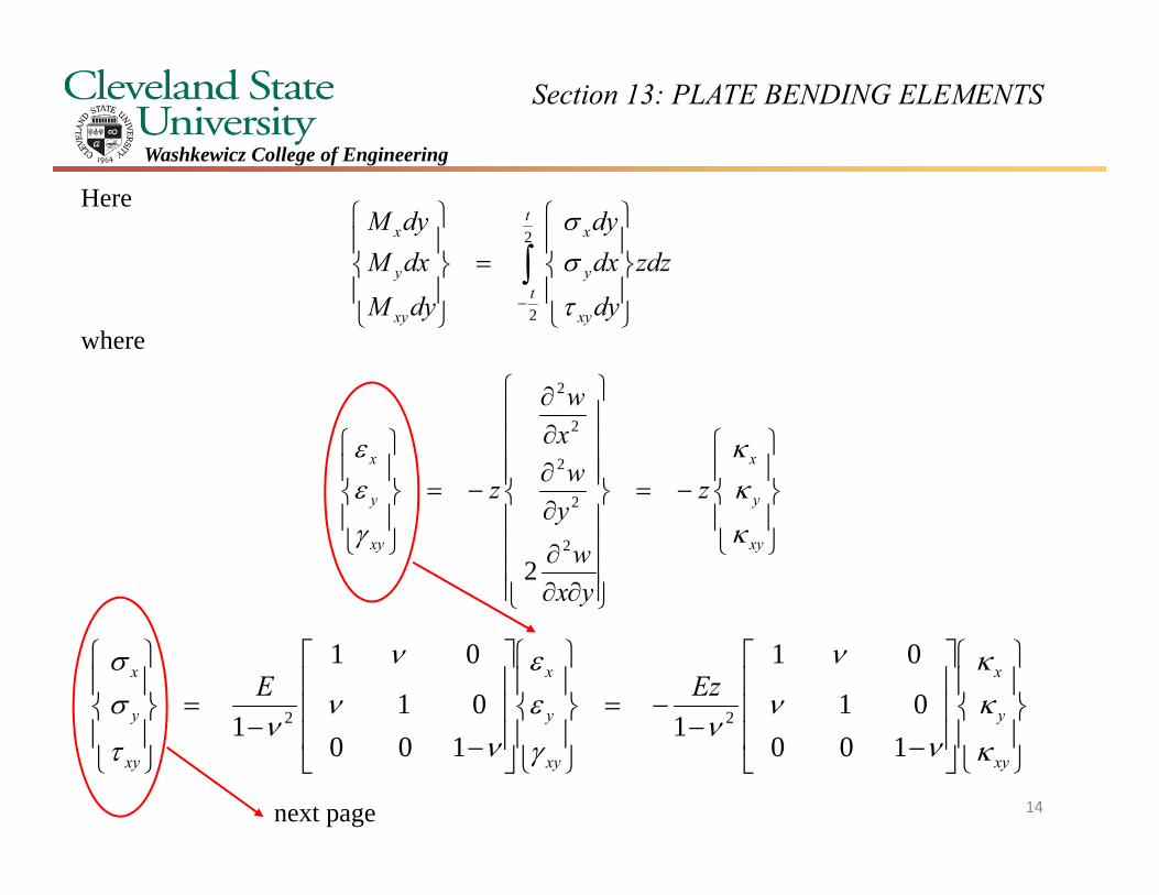
Here
where
14
Section 13: PLATE BENDING ELEMENTS
Washkewicz College of Engineering
xy
y
x
t
txy
y
x
t
txy
x
x
xy
y
x
Et
dzEz
zdz
M
MM
2100
01
01
112
2100
01
01
1
2
3
2
2
2
2
2
2
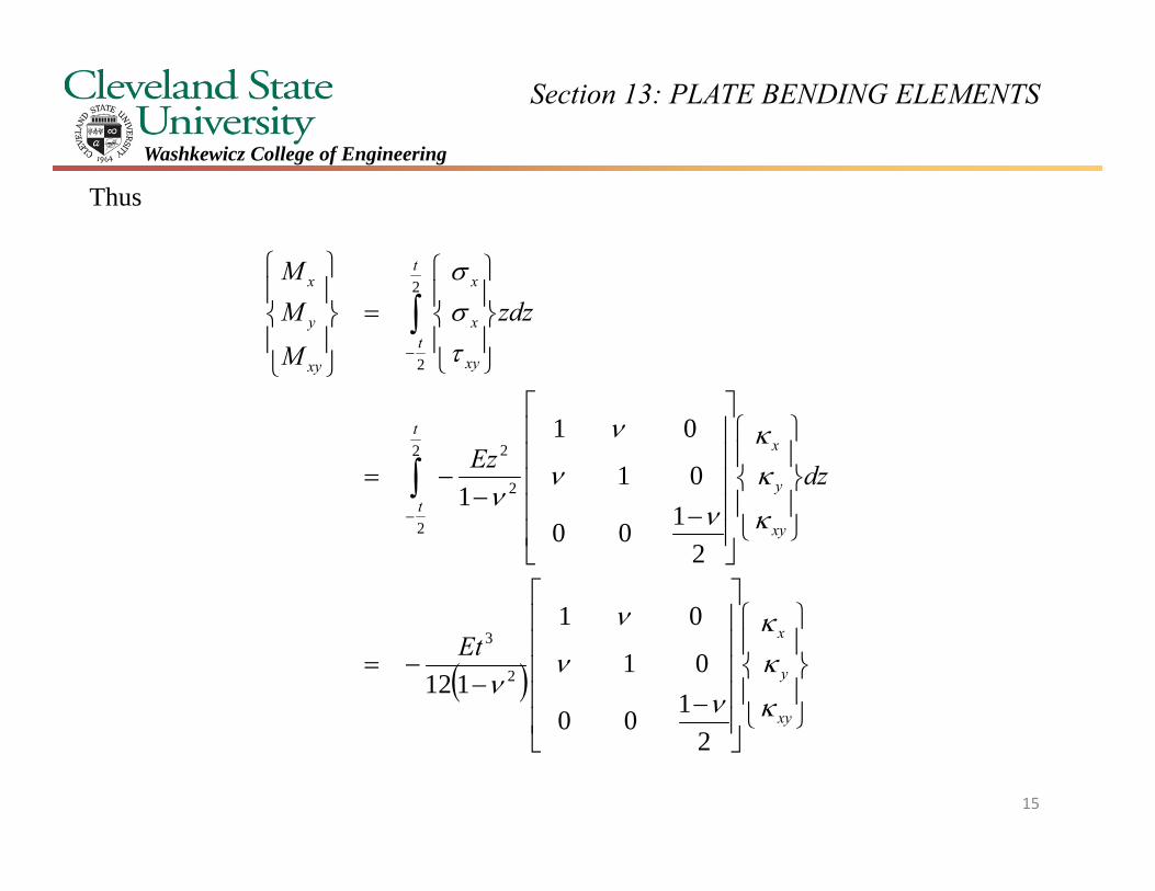
Thus
15
Section 13: PLATE BENDING ELEMENTS
Washkewicz College of Engineering
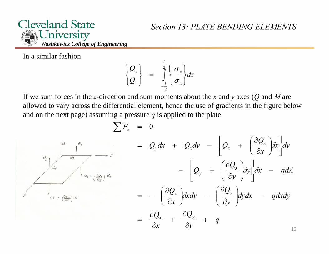
In a similar fashion
If we sum forces in the z-direction and sum moments about the x and y axes (Q and M are allowed to vary across the differential element, hence the use of gradients in the figure below and on the next page) assuming a pressure q is applied to the plate
2
2
t
t x
x
y
x dzQQ
qy
Qx
Q
qdxdydydxy
Qdxdy
xQ
qdAdxdyy
dydxx
QQdyQdxQ
F
yx
yx
yy
xxxy
z
0
16
Section 13: PLATE BENDING ELEMENTS
Washkewicz College of Engineering
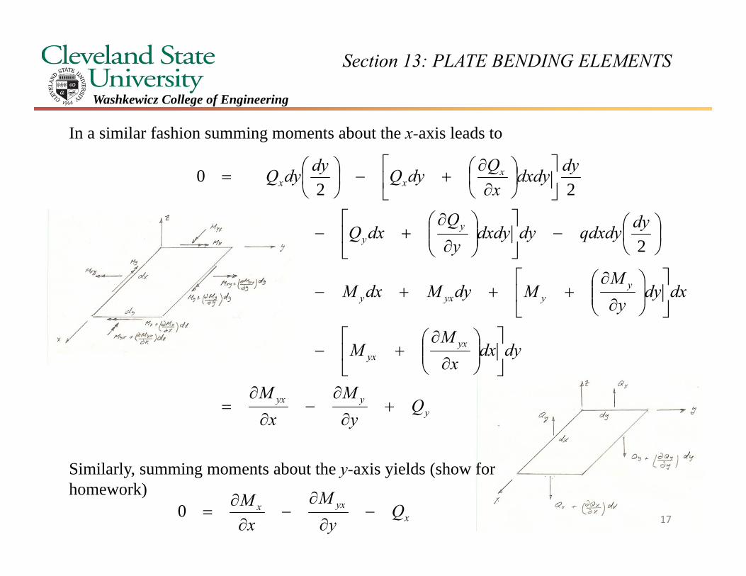
In a similar fashion summing moments about the x-axis leads to
Similarly, summing moments about the y-axis yields (show for homework)
yyyx
yxyx
yyyxy
yy
xxx
Qy
Mx
M
dydxx
MM
dxdyy
MMdyMdxM
dyqdxdydydxdyy
QdxQ
dydxdyx
QdyQdydyQ
2
220
xyxx Q
yM
xM
0 17
Section 13: PLATE BENDING ELEMENTS
Washkewicz College of Engineering
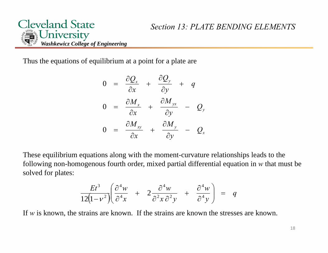
Thus the equations of equilibrium at a point for a plate are
These equilibrium equations along with the moment-curvature relationships leads to the following non-homogenous fourth order, mixed partial differential equation in w that must be solved for plates:
If w is known, the strains are known. If the strains are known the stresses are known.
xyxy
yyxx
yx
Qy
Mx
M
Qy
Mx
M
qy
Qx
Q
0
0
0
qyw
yxw
xwEt
4
4
22
4
4
4
2
3
2112
18
Section 13: PLATE BENDING ELEMENTS
Washkewicz College of Engineering
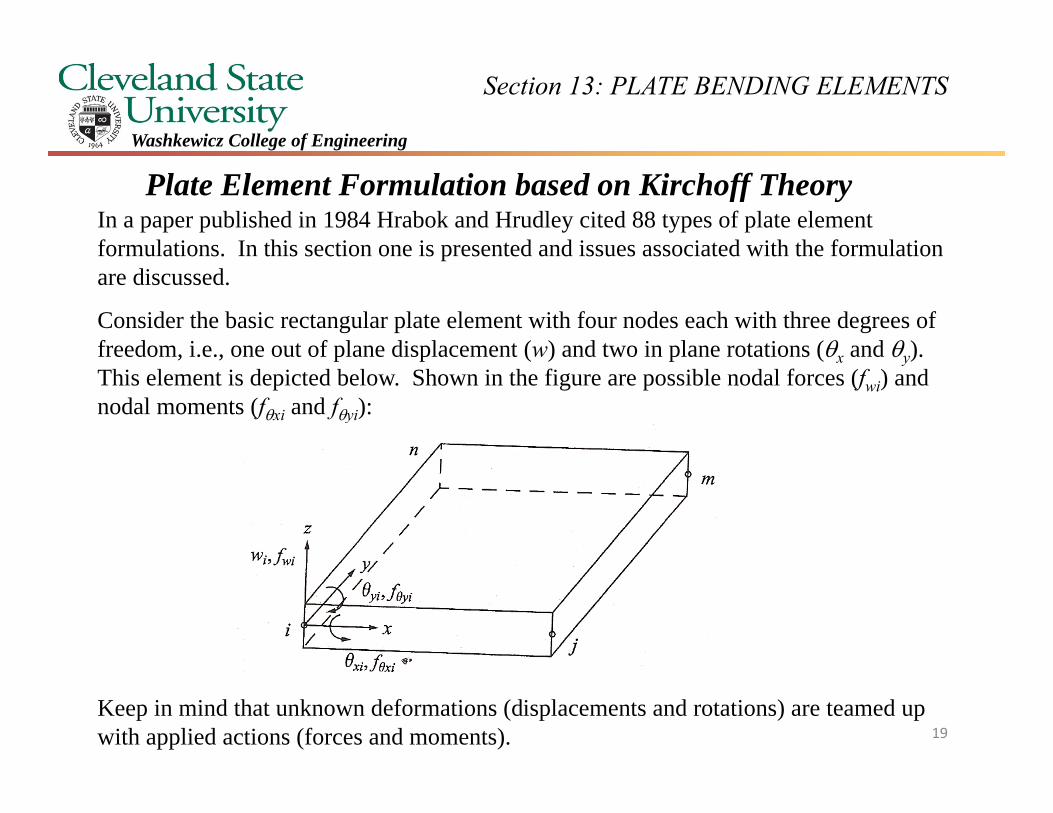
Plate Element Formulation based on Kirchoff TheoryIn a paper published in 1984 Hrabok and Hrudley cited 88 types of plate element formulations. In this section one is presented and issues associated with the formulation are discussed.
Consider the basic rectangular plate element with four nodes each with three degrees of freedom, i.e., one out of plane displacement (w) and two in plane rotations (x and y). This element is depicted below. Shown in the figure are possible nodal forces (fwi) and nodal moments (fxi and fyi):
Keep in mind that unknown deformations (displacements and rotations) are teamed up with applied actions (forces and moments). 19
Section 13: PLATE BENDING ELEMENTS
Washkewicz College of Engineering
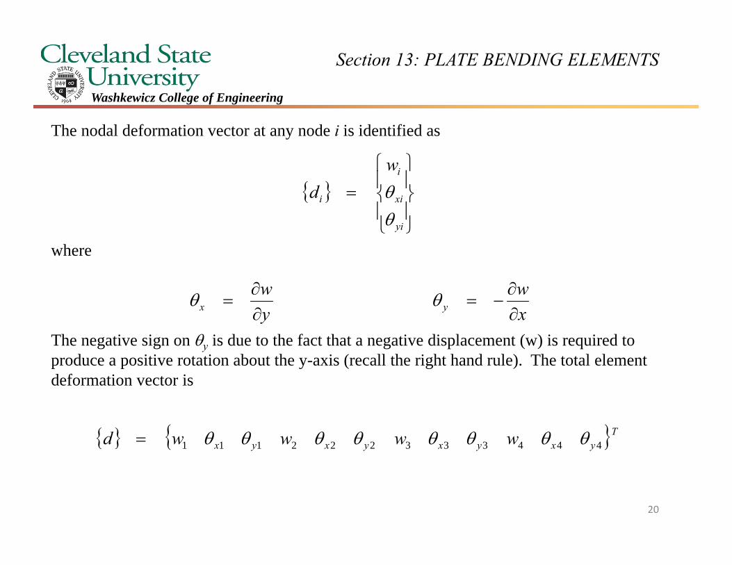
The nodal deformation vector at any node i is identified as
where
The negative sign on y is due to the fact that a negative displacement (w) is required to produce a positive rotation about the y-axis (recall the right hand rule). The total element deformation vector is
yi
xi
i
i
wd
xw
yw
yx
Tyxyxyxyx wwwwd 444333222111
20
Section 13: PLATE BENDING ELEMENTS
Washkewicz College of Engineering
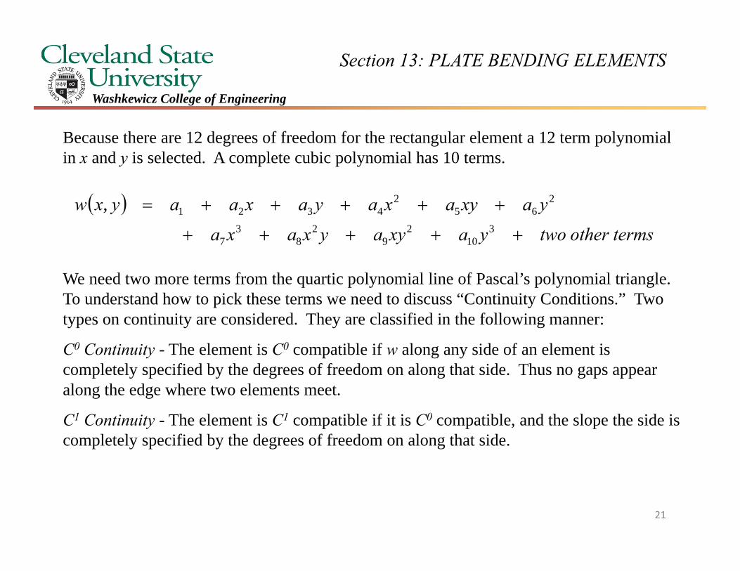
Because there are 12 degrees of freedom for the rectangular element a 12 term polynomial in x and y is selected. A complete cubic polynomial has 10 terms.
We need two more terms from the quartic polynomial line of Pascal’s polynomial triangle. To understand how to pick these terms we need to discuss “Continuity Conditions.” Two types on continuity are considered. They are classified in the following manner:
C0 Continuity - The element is C0 compatible if w along any side of an element is completely specified by the degrees of freedom on along that side. Thus no gaps appear along the edge where two elements meet.
C1 Continuity - The element is C1 compatible if it is C0 compatible, and the slope the side is completely specified by the degrees of freedom on along that side.
termsothertwoyaxyayxaxa
yaxyaxayaxaayxw
3
102
92
83
7
265
24321,
21
Section 13: PLATE BENDING ELEMENTS
Washkewicz College of Engineering
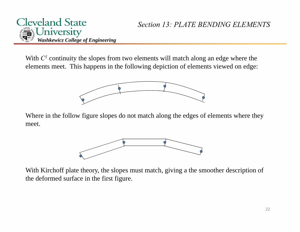
With C1 continuity the slopes from two elements will match along an edge where the elements meet. This happens in the following depiction of elements viewed on edge:
Where in the follow figure slopes do not match along the edges of elements where they meet.
With Kirchoff plate theory, the slopes must match, giving a the smoother description of the deformed surface in the first figure.
22
Section 13: PLATE BENDING ELEMENTS
Washkewicz College of Engineering
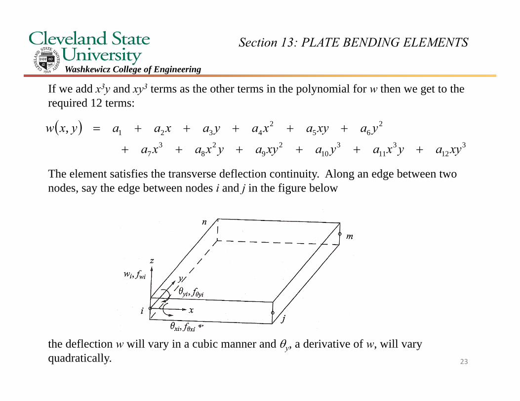
If we add x3y and xy3 terms as the other terms in the polynomial for w then we get to the required 12 terms:
The element satisfies the transverse deflection continuity. Along an edge between two nodes, say the edge between nodes i and j in the figure below
the deflection w will vary in a cubic manner and y, a derivative of w, will vary quadratically.
3
123
113
102
92
83
7
265
24321,
xyayxayaxyayxaxa
yaxyaxayaxaayxw
23
Section 13: PLATE BENDING ELEMENTS
Washkewicz College of Engineering
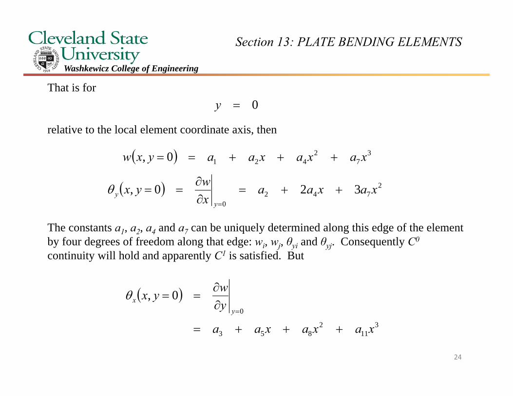
That is for
relative to the local element coordinate axis, then
The constants a1, a2, a4 and a7 can be uniquely determined along this edge of the element by four degrees of freedom along that edge: wi, wj, θyi and θyj. Consequently C0
continuity will hold and apparently C1 is satisfied. But
37
24210, xaxaxaayxw
0y
2742
0
320, xaxaaxwyx
yy
311
2853
0
0,
xaxaxaa
ywyx
yx
24
Section 13: PLATE BENDING ELEMENTS
Washkewicz College of Engineering
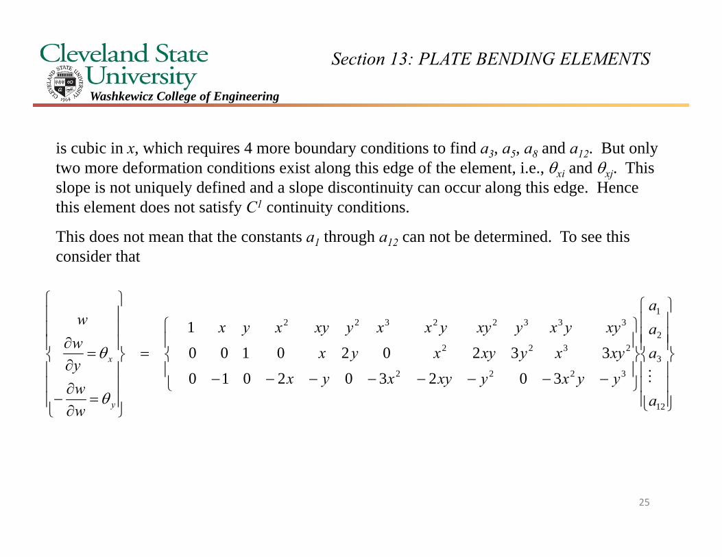
is cubic in x, which requires 4 more boundary conditions to find a3, a5, a8 and a12. But only two more deformation conditions exist along this edge of the element, i.e., xi and xj. This slope is not uniquely defined and a slope discontinuity can occur along this edge. Hence this element does not satisfy C1 continuity conditions.
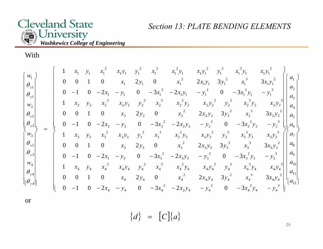
This does not mean that the constants a1 through a12 can not be determined. To see this consider that
12
3
2
1
3222
2322
33322322
302302010332020100
1
a
aaa
yyxyxyxyxxyxyxyxyx
xyyxyxyyxxyxyxyx
wwyww
y
x
25
Section 13: PLATE BENDING ELEMENTS
Washkewicz College of Engineering
With
or
12
11
10
9
8
7
6
5
4
3
2
1
344
24
2442
2444
244
34
2444
2444
3444
34
34
2444
24
34
2444
2444
333
23
2333
2331
233
33
2333
2333
3333
33
33
2333
23
33
2333
2333
322
22
2222
2222
222
32
2222
2222
3222
32
32
2222
22
32
2222
2222
311
21
2111
2111
211
31
2111
2111
3111
31
31
2111
21
31
2111
2111
4
4
4
3
3
3
2
2
2
1
1
1
302302010
332020100
1
302302010
332020100
1
302302010
332020100
1
302302010
332020100
1
aaaaaaaaaaaa
yyxyyxxyx
yxxyyxxyx
yxyxyyxyxxyyxxyx
yyxyyxxyx
yxxyyxxyx
yxyxyyxyxxyyxxyx
yyxyyxxyx
yxxyyxxyx
yxyxyyxyxxyyxxyx
yyxyyxxyx
yxxyyxxyx
yxyxyyxyxxyyxxyx
w
w
w
w
y
x
y
x
y
x
y
x
aCd 26
Section 13: PLATE BENDING ELEMENTS
Washkewicz College of Engineering
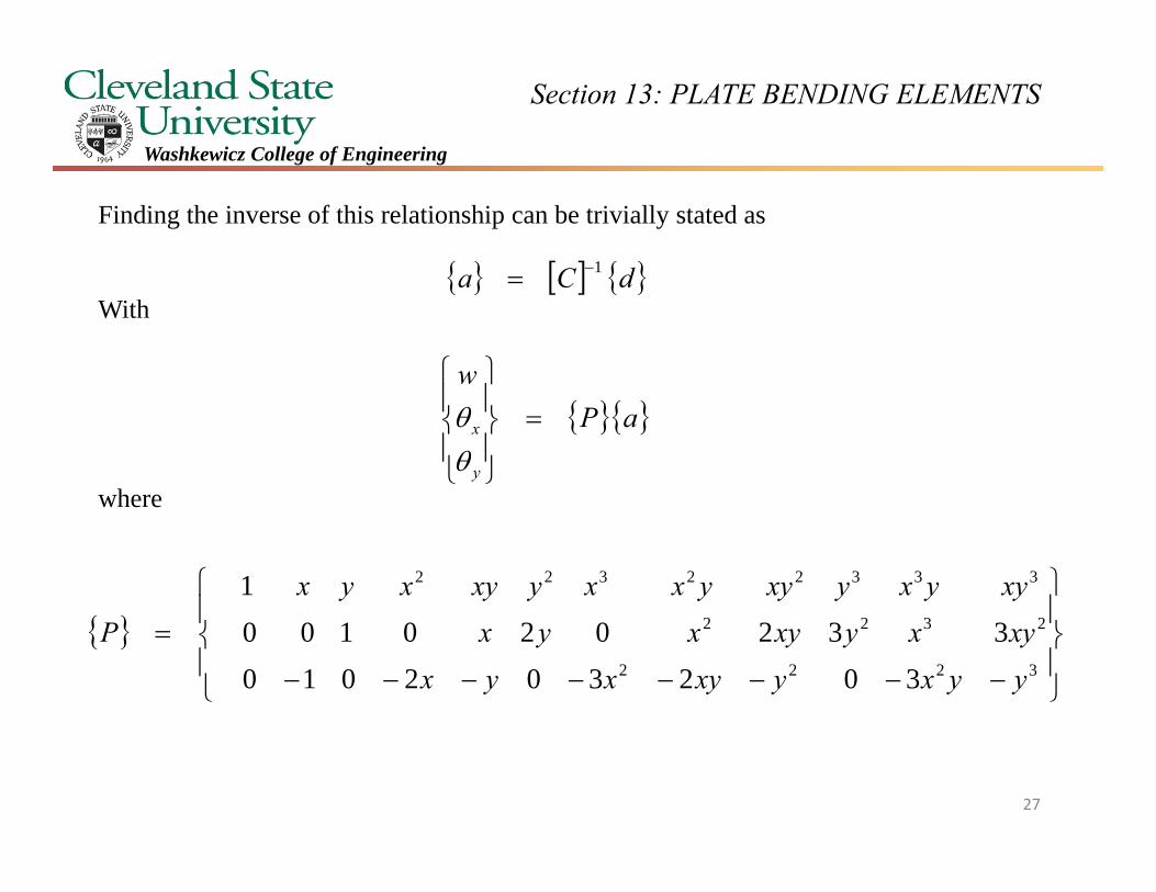
Finding the inverse of this relationship can be trivially stated as
With
where
dCa 1
aPw
y
x
3222
2322
33322322
302302010332020100
1
yyxyxyxyxxyxyxyxyx
xyyxyxyyxxyxyxyxP
27
Section 13: PLATE BENDING ELEMENTS
Washkewicz College of Engineering
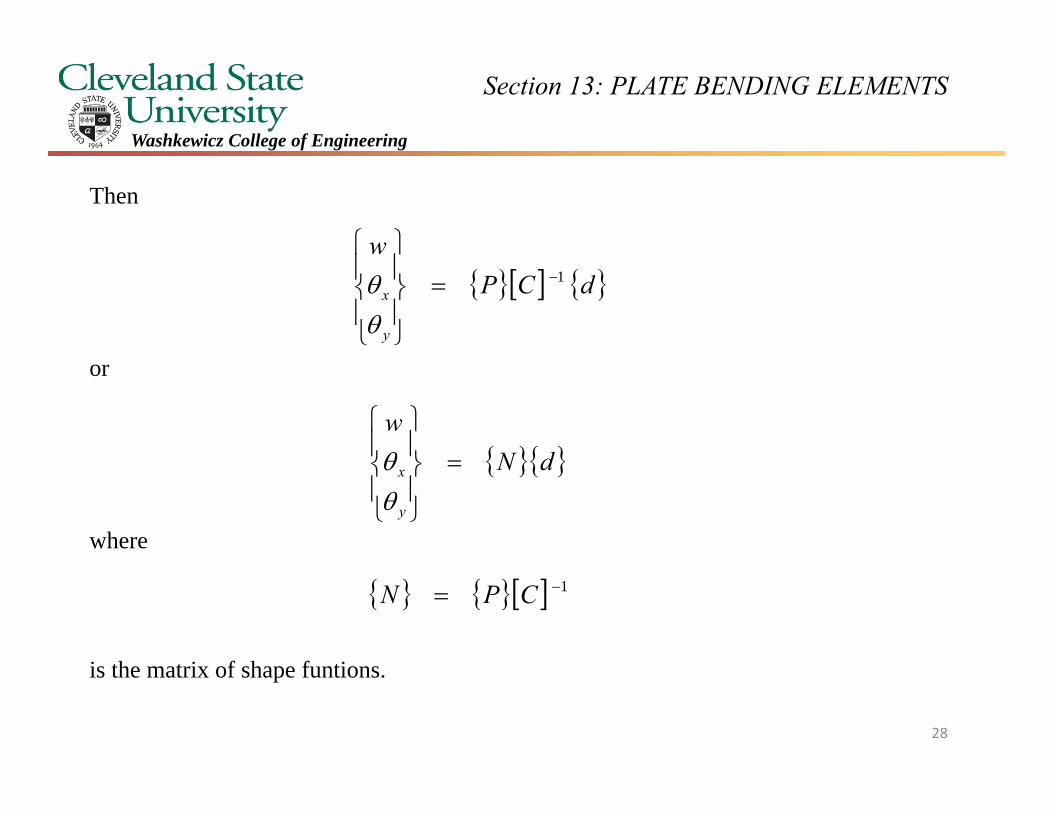
Then
or
where
is the matrix of shape funtions.
dCPw
y
x1
dNw
y
x
1 CPN
28
Section 13: PLATE BENDING ELEMENTS
Washkewicz College of Engineering
212
211985
121096
11874
2
2
2
2
2
66442
66226262
2yaxayaxaa
xyayaxaaxyayaxaa
z
yxw
yw
xw
z
z
xy
y
x
xy
y
x
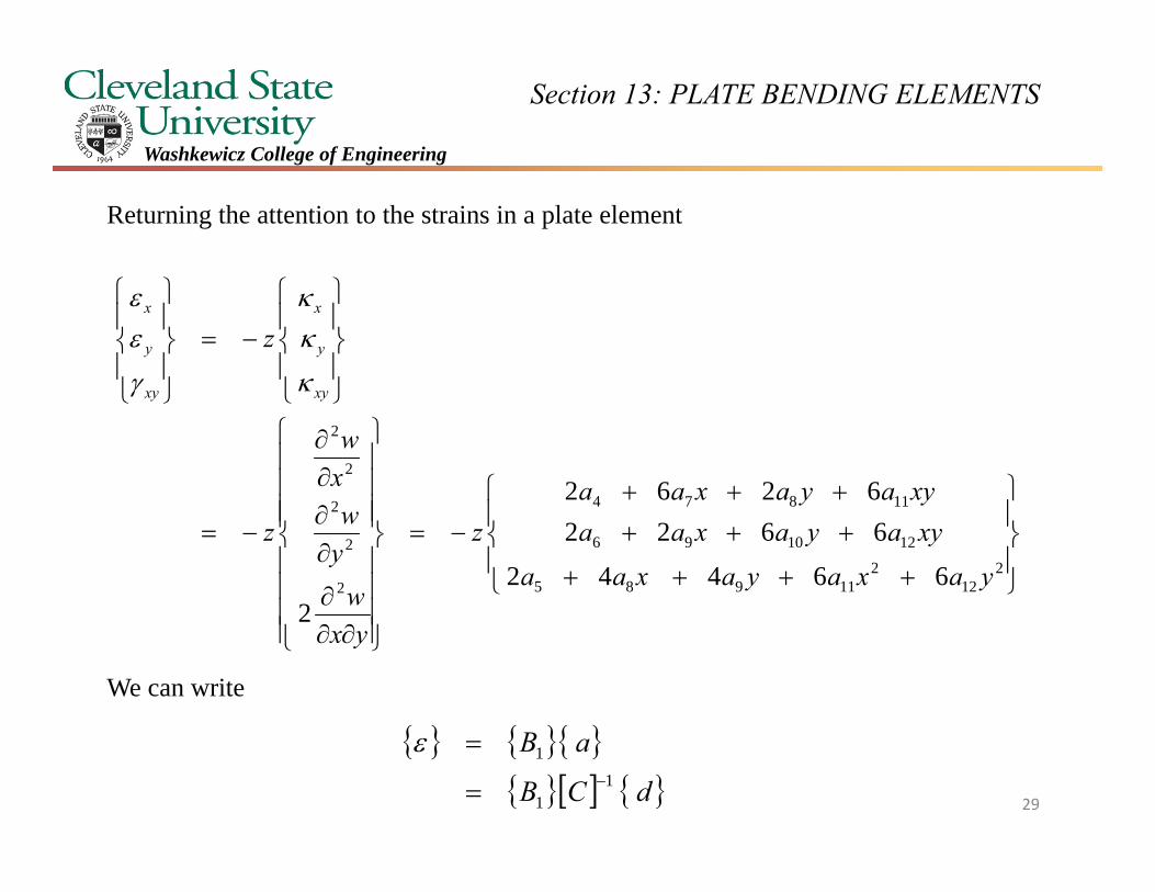
Returning the attention to the strains in a plate element
We can write
dCB
aB1
1
1
29
Section 13: PLATE BENDING ELEMENTS
Washkewicz College of Engineering
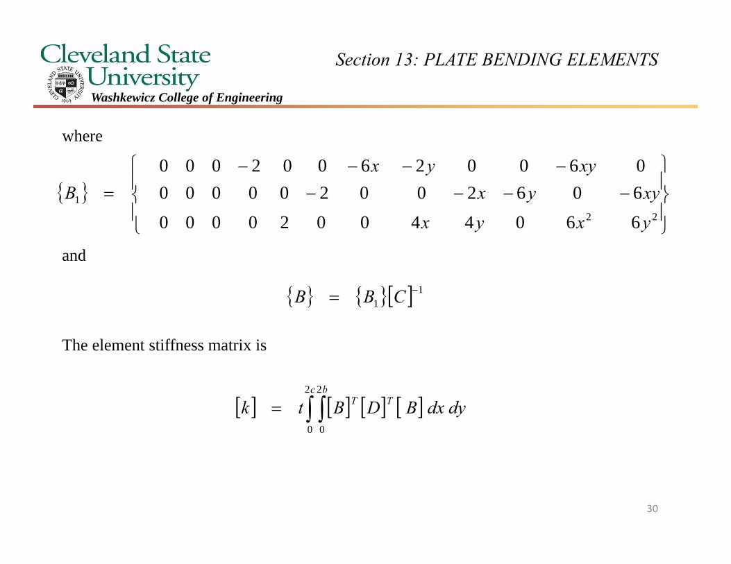
where
and
The element stiffness matrix is
221
660440020000606200200000060026002000
yxyxxyyx
xyyxB
11
CBB
dydxBDBtkc b
TT 2
0
2
0
30
Section 13: PLATE BENDING ELEMENTS
Washkewicz College of Engineering
There are many different ways of interpolating deformations over a plate, leading to many different types of plate elements having been proposed for Kirchoff’s plate theory. The same issue comes up for Mindlin-Reisner plate theory.
Some proposed elements for Kirchoff’s theory have encountered problems with locking -a refusal of the element to deform in some circumstances, as the set of equations becomes over-constrained, due to inconsistent assumptions being made. This is referred to as shear locking.
Other elements have had the opposite problem of lacking stiffness to resist certain “zero-energy” modes of deformation. These spurious modes of deformation then dominate the solution. Another name for this is “hourglass” deformation, as the unwanted in-plane deformation of a quadratic element resembles this shape.
31