Embed Size (px)
Citation preview
INTERNATIONAL JOURNAL OF CIVIL AND STRUCTURAL ENGINEERING
Volume 3, No 2, 2012
© Copyright 2010 All rights reserved Integrated Publishing services
Research article ISSN 0976 – 4399
Received on September 2012 Published on November 2012 346
Seismic performance of semi-rigid base connection model of cable-stayed
bridge tower Shehata E. Abdel Raheem
1, Toshiro Hayashikawa
2
1- Assoc. Prof., Taibah University, Madinah Munawarh, KSA (on leave, Assiut University,
Egypt
2- Prof., Graduate School of Engineering, Hokkaido University, Sapporo, Japan
doi:10.6088/ijcser.201203013033
ABSTRACT
A quite general base connection modeling capable of accurately representing material and
geometrical nonlinear behavior of the base plate and arbitrary nonlinear contact with concrete
foundation has been demonstrated and its implementation in a finite element nonlinear
seismic analysis is presented. A time domain finite element methodology for nonlinear
dynamic analysis problem that accounts for base connection lift-off and the inelastic behavior
of anchor bolts through an incremental-iterative procedure is developed. A representative
problem of cable-stayed bridges tower subjected to strong ground motion is analyzed. The
maximum bearing stress on the concrete foundation as well as the tension force per anchor
bolt that necessary to design the anchorage system is computed.
Keywords: Bridge tower; Cable-stayed bridges; Energy dissipation; Seismic design;
Nonlinear response; Base connection; Finite element modeling; Base plate lift-off.
1. 1. Introduction
The base connection between columns and foundation is one of the most important elements
in steel frame structures and has a great influence on the entire structural behavior as it is
recognized from analytical studies (Krishnamurthy and Thambirathnam 1990; Colson 1991;
Ermopoulos and Stamatopoulos 1996; and Ermopoulos and Michaltsos 1998) and
experimental investigations (Targowski et al. 1993; and Popov and Takhirov 2002). The
nonlinearities that arise due to the particular behavior of the connections components make
the problem of the analysis of these structures very difficult (Rothert et al. 1992; and Piluso
and Faella 2001). Many observers have reported damage at column bases during past
earthquakes (Astaneh-Asl et al. 1994; Nakashima et al. 1995; Committee of Earthquake
Engineering 1996; and Northridge Reconnaissance Team 1996). The Hyogoken Nanbu
earthquake of January 1995 in Japan caused serious damage in a large number of steel
structures. One of the reasons that have been registered is the failure of the column bases,
resulting in such damage, which proved once again that special attention must be paid to the
proper modeling and the right construction in such a way that failure should be avoided in
these connections.
The most common arrangement of the base connections is that a base plate welded at the
bottom end of the column with anchor bolts embedded in the concrete, keeping the base-plate
in contact with the foundation. Most of the modern codes (Wald 1993; and Ermopoulos and
Stamatopoulos 1996) give little information to the users about the real behavior of column
bases, and practicing engineers usually treat this connection that represent the support
conditions of the framed structures either as pinned or fixed, although it has been proved that
Seismic performance of semi-rigid base connection model of cable-stayed bridge tower
Shehata E. Abdel Raheem, Toshiro Hayashikawa
International Journal of Civil and Structural Engineering
Volume 3 Issue 2 2012
347
these connections are semi-rigid and the real condition lies between these two extreme cases.
The degree of semi-rigidity depends on the properties and the configuration of various
elements that form the connection. Seismic design practice for this class of connections has
not been well developed mainly because of the rather limited number of analytical and
experimental studies. Most of the experimental studies have been performed on reduced scale
specimens representing basic types of connections simulating a column welded to an exposed
base plate, which in turn is connected to a concrete foundation through anchor bolts. The
performance of the base connection depends on the cyclic performance of the anchors and the
surrounding concrete foundation. Much research work is needed in order to better understand
the seismic behavior and to formulate improved design procedures. The steel frames behavior
could only be accomplished through nonlinear dynamic analyses of complete frame systems
with actual support condition (Jaspart and Vadegans 1998; Nakashima 1998; and Swanson
and Leon 2001).
The behavior of steel framed structures depends on the performance of their connections. The
design of base connections should capable of spreading the load so as to maintain the bearing
pressures under the allowable values and connecting the base plate and column to the
concrete foundation. But strong earthquake lateral forces can induce base overturning
moments that exceed the available overturning resistance due to gravity loads causing base
connection anchor bolts lift-off. The objective of this study is to develop an accurate and
convenient model to predict the performance of cable-stayed bridge steel tower base
connections under dynamic loadings; to address the problem of base plate lift-off and to
formulate improved design procedures. A finite element methodology based on theoretical
approach and computer simulations for nonlinear dynamic analysis problem including base
connection modeling is presented. The base connection model takes into account: connection
lift-off; the inelastic behavior of anchor bolts, material/geometrical nonlinear behavior of the
base plate and nonlinear contact with concrete foundation through an incremental iterative
procedure. The base connection is idealized by a spring system that considers connection
various parameters of base plate, anchor bolts and material properties. A representative
problem of cable-stayed bridge tower subjected to strong ground motion recoded at JR
Takatori Station during Hyogoken Nanbu earthquake 1995 is analyzed. In addition, the
maximum bearing stress on the concrete foundation as well as the seismic demand of the
anchor bolt under strong earthquake that is the most important for design of the anchorage
system is computed.
2. 2. Finite element model
2.1 Tower structure modeling
The steel tower of a cable-stayed bridge located in Hokkaido is considered in this study.
Figure 1 shows a general view of the cable-stayed bridge elevation. The steel tower is taken
out of the bridge and modeled as three-dimensional frame structure. A fiber flexural element
is developed for characterization of the tower structure, in which the element incorporates
both geometric and material nonlinearities. The stress-strain relationship of the beam element
is modeled as bilinear type with kinematic strain hardening rule. The yield stress and the
modulus of elasticity are equal to 355 MPa (SM490Y) and 200GPa, respectively; the strain
hardening in the plastic region is 0.01.
Inelasticity of the flexure element is accounted for by the division of the cross section into a
number of fiber zones with uniaxial plasticity defining the normal stress-strain relationship
Seismic performance of semi-rigid base connection model of cable-stayed bridge tower
Shehata E. Abdel Raheem, Toshiro Hayashikawa
International Journal of Civil and Structural Engineering
Volume 3 Issue 2 2012
348
for each zone, the element stress resultants are determined by integration of the fiber zone
stresses over the cross section of the element. By tracking the center of the yield region, the
evolution of the yield surface is monitored, and a stress update algorithm is implemented to
allow accurate integration of the stress-strain constitutive law for strain increments, including
full load reversals. To ensure path dependence of the solution, the implementation of the
plasticity model for the implicit Newton Raphson equilibrium iterations employs a stress
integration whereby the element stresses are updated from the last fully converged
equilibrium state. The transformation between element local and global coordinates is
accomplished through a vector translation of element forces and displacements based on the
direction cosines of the current updated element coordinate system.
34.00 34.00
36.0
068.0
0
68.0
036.0
0
8 x 11.5 = 92.00 34.50 34.50 8 x 11.50 = 92.00 31.00 8 x 11.50 = 92.00 34.50 34.50 8x 11.5 = 92.00
74.30 115.00 284.00 115.00 81.10
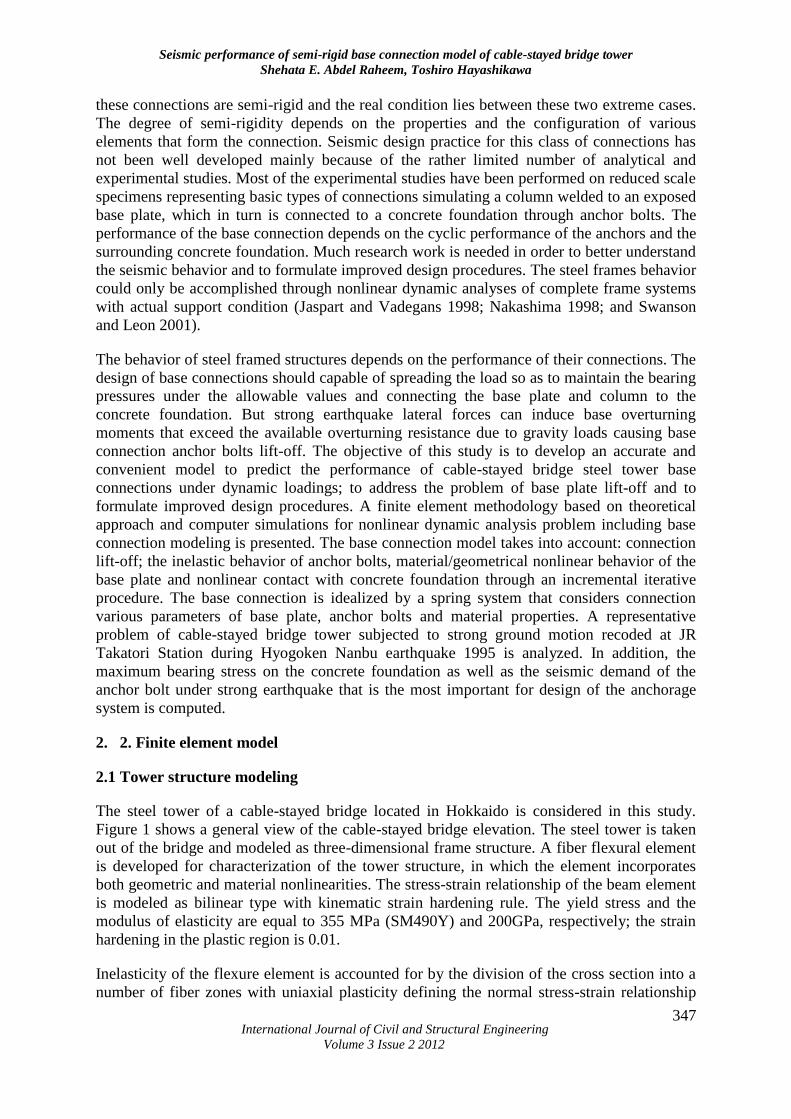
Figure 1: General view of the cable-stayed bridge (m)
This tower has nine cables in each side; the dead load of the stiffening girder is considered to
be equivalent to the vertical component of the pretension force of the cables and acted
vertically at the joint of cables. The inertia forces acting on the steel tower from the stiffening
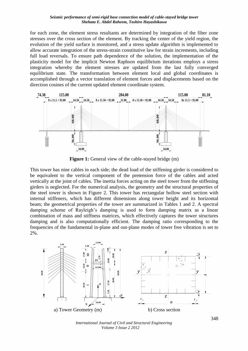
girders is neglected. For the numerical analysis, the geometry and the structural properties of
the steel tower is shown in Figure 2. This tower has rectangular hollow steel section with
internal stiffeners, which has different dimensions along tower height and its horizontal
beam; the geometrical properties of the tower are summarized in Tables 1 and 2. A spectral
damping scheme of Rayleigh’s damping is used to form damping matrix as a linear
combination of mass and stiffness matrices, which effectively captures the tower structures
damping and is also computationally efficient. The damping ratio corresponding to the
frequencies of the fundamental in-plane and out-plane modes of tower free vibration is set to
2%.
14.5
01
7.0
0
20.0
0
X
Z
48.0
0
18.00
68.0
0
68.0
0
3.502.40
13.00
36.5
0
IIII
II
IV
14.504
2.7
0
X
Z
Y
1.5
03
7.5
02
4.0
05
.00
z
t
B1
b
y t
zt
22
a
t
y
A
t 1
t2
2
11
a) Tower Geometry (m) b) Cross section
Seismic performance of semi-rigid base connection model of cable-stayed bridge tower
Shehata E. Abdel Raheem, Toshiro Hayashikawa
International Journal of Civil and Structural Engineering
Volume 3 Issue 2 2012
349
Figure 2: Steel tower of cable-stayed bridge
Table 1: Cross section dimensions of tower parts
Tower
parts
Outer dimension (cm) Stiffener dimension (cm)
A B t1 t2 a b t11 t22
I 350 240 2.2 3.2 25 22 3.6 3.0
II 350 240 2.2 3.2 22 20 3.2 2.8
III 350 240 2.2 2.8 20 20 2.8 2.2
IV 350 270 2.2 2.6 31 22 3.5 2.4
Table 2: Cross sectional properties of tower
Cross sectional
properties Area (m
2)
Moment of Inertia (m4) Torsion
constant (m4) Iyy Izz
I 0.4856 0.4842 0.7952 0.6391
II 0.4560 0.4617 0.7567 0.6391
III 0.4016 0.4050 0.6856 0.5976
IV 0.4621 0.5680 0.7703 0.6903
2.2 Base connection components modeling
In recent decades, long span bridges such as cable-stayed bridges have gained much
popularity. For these bridges, steel towers are preferred because of their efficient utilization
of structural materials, improved speed of construction, earthquake resistance, and so on.
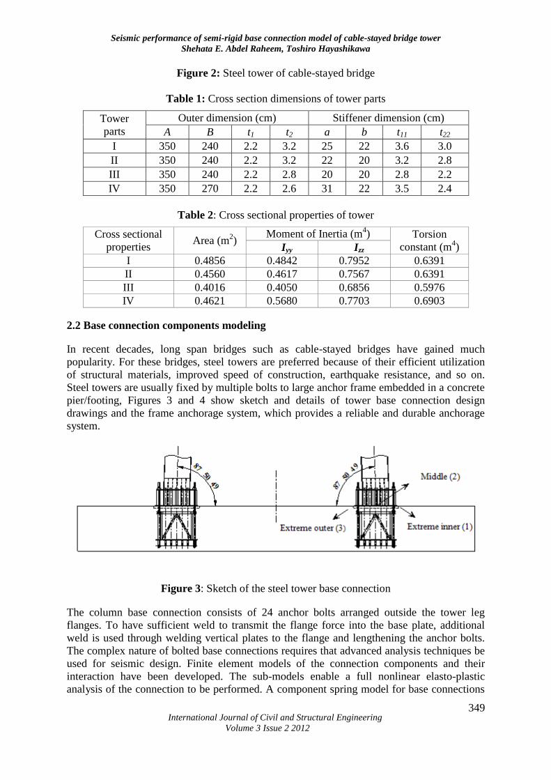
Steel towers are usually fixed by multiple bolts to large anchor frame embedded in a concrete
pier/footing, Figures 3 and 4 show sketch and details of tower base connection design
drawings and the frame anchorage system, which provides a reliable and durable anchorage
system.
Figure 3: Sketch of the steel tower base connection
The column base connection consists of 24 anchor bolts arranged outside the tower leg
flanges. To have sufficient weld to transmit the flange force into the base plate, additional
weld is used through welding vertical plates to the flange and lengthening the anchor bolts.
The complex nature of bolted base connections requires that advanced analysis techniques be
used for seismic design. Finite element models of the connection components and their
interaction have been developed. The sub-models enable a full nonlinear elasto-plastic
analysis of the connection to be performed. A component spring model for base connections
Seismic performance of semi-rigid base connection model of cable-stayed bridge tower
Shehata E. Abdel Raheem, Toshiro Hayashikawa
International Journal of Civil and Structural Engineering
Volume 3 Issue 2 2012
350
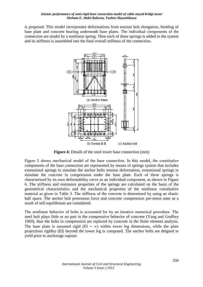
is proposed. This model incorporates deformations from tension bolt elongation, bending of
base plate and concrete bearing underneath base plates. The individual components of the
connection are model by a nonlinear spring. Then each of these springs is added to the system
and its stiffness is assembled into the final overall stiffness of the connection.
Figure 4: Details of the steel tower base connection (mm)
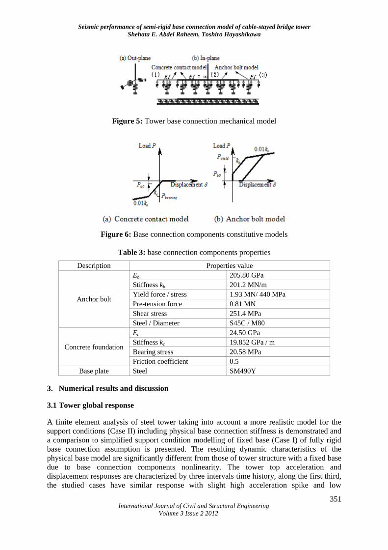
Figure 5 shows mechanical model of the base connection. In this model, the constitutive
components of the base connection are represented by means of springs system that includes
extensional springs to simulate the anchor bolts tension deformation, extensional springs to
simulate the concrete in compression under the base plate. Each of these springs is
characterized by its own deformability curve as an individual component, as shown in Figure
6. The stiffness and resistance properties of the springs are calculated on the basis of the
geometrical characteristics and the mechanical properties of the nonlinear constitutive
material as given in Table 3. The stiffness of the concrete is determined by using an elastic
half space. The anchor bolt pretension force and concrete compression pre-stress state as a
result of self-equilibrium are considered.
The nonlinear behavior of bolts is accounted for by an iterative numerical procedure. The
steel bolt plays little or no part in the compressive behavior of concrete (Yang and Godfrey
1969), thus the bolts in compression are replaced by concrete in the finite element analysis.
The base plate is assumed rigid (EI = ) within tower leg dimensions, while the plate
projections rigidity (EI) beyond the tower leg is computed. The anchor bolts are deigned to
yield prior to anchorage rupture.
Seismic performance of semi-rigid base connection model of cable-stayed bridge tower
Shehata E. Abdel Raheem, Toshiro Hayashikawa
International Journal of Civil and Structural Engineering
Volume 3 Issue 2 2012
351
Figure 5: Tower base connection mechanical model
Figure 6: Base connection components constitutive models
Table 3: base connection components properties
Description Properties value
Anchor bolt
Eb 205.80 GPa
Stiffness kb 201.2 MN/m
Yield force / stress 1.93 MN/ 440 MPa
Pre-tension force 0.81 MN
Shear stress 251.4 MPa
Steel / Diameter S45C / M80
Concrete foundation
Ec 24.50 GPa
Stiffness kc 19.852 GPa / m
Bearing stress 20.58 MPa
Friction coefficient 0.5
Base plate Steel SM490Y
3. Numerical results and discussion
3.1 Tower global response
A finite element analysis of steel tower taking into account a more realistic model for the
support conditions (Case II) including physical base connection stiffness is demonstrated and
a comparison to simplified support condition modelling of fixed base (Case I) of fully rigid
base connection assumption is presented. The resulting dynamic characteristics of the
physical base model are significantly different from those of tower structure with a fixed base
due to base connection components nonlinearity. The tower top acceleration and
displacement responses are characterized by three intervals time history, along the first third,
the studied cases have similar response with slight high acceleration spike and low
Seismic performance of semi-rigid base connection model of cable-stayed bridge tower
Shehata E. Abdel Raheem, Toshiro Hayashikawa
International Journal of Civil and Structural Engineering
Volume 3 Issue 2 2012
352
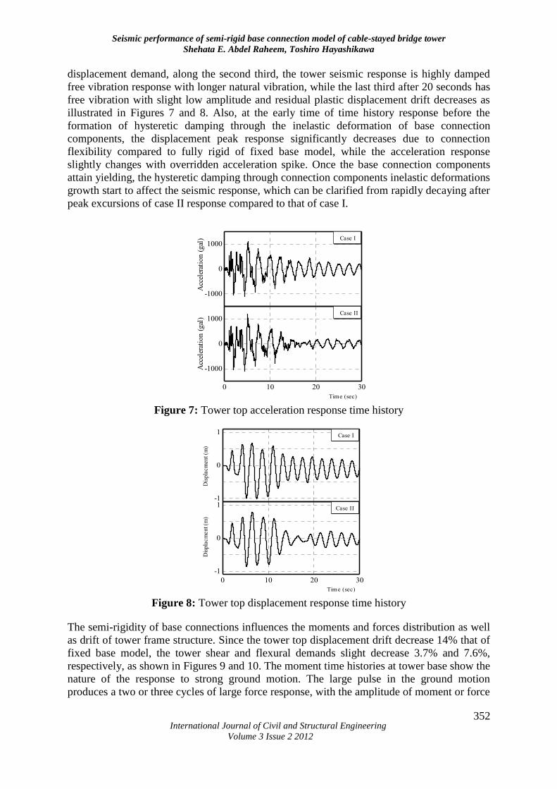
displacement demand, along the second third, the tower seismic response is highly damped
free vibration response with longer natural vibration, while the last third after 20 seconds has
free vibration with slight low amplitude and residual plastic displacement drift decreases as
illustrated in Figures 7 and 8. Also, at the early time of time history response before the
formation of hysteretic damping through the inelastic deformation of base connection
components, the displacement peak response significantly decreases due to connection
flexibility compared to fully rigid of fixed base model, while the acceleration response
slightly changes with overridden acceleration spike. Once the base connection components
attain yielding, the hysteretic damping through connection components inelastic deformations
growth start to affect the seismic response, which can be clarified from rapidly decaying after
peak excursions of case II response compared to that of case I.
-1000
0
1000
Acc
eler
atio
n (
gal
) Case I
0 10 20 30
-1000
0
1000
Acc
eler
atio
n (
gal
)
Case II
Time (sec) Figure 7: Tower top acceleration response time history
-1
0
1
Dis
pla
cm
ent (m
)
Case I
0 10 20 30
-1
0
1
Dis
pla
cm
ent (m
)
Case II
Time (sec) Figure 8: Tower top displacement response time history
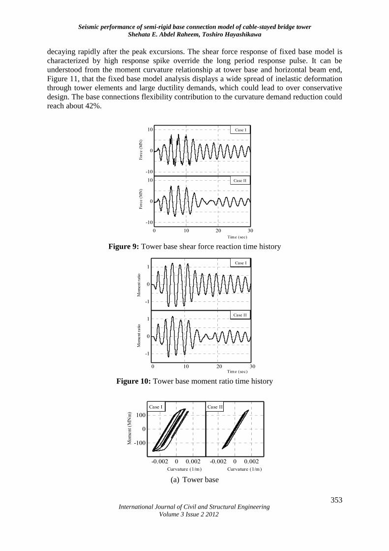
The semi-rigidity of base connections influences the moments and forces distribution as well
as drift of tower frame structure. Since the tower top displacement drift decrease 14% that of
fixed base model, the tower shear and flexural demands slight decrease 3.7% and 7.6%,
respectively, as shown in Figures 9 and 10. The moment time histories at tower base show the
nature of the response to strong ground motion. The large pulse in the ground motion
produces a two or three cycles of large force response, with the amplitude of moment or force
Seismic performance of semi-rigid base connection model of cable-stayed bridge tower
Shehata E. Abdel Raheem, Toshiro Hayashikawa
International Journal of Civil and Structural Engineering
Volume 3 Issue 2 2012
353
decaying rapidly after the peak excursions. The shear force response of fixed base model is
characterized by high response spike override the long period response pulse. It can be
understood from the moment curvature relationship at tower base and horizontal beam end,
Figure 11, that the fixed base model analysis displays a wide spread of inelastic deformation
through tower elements and large ductility demands, which could lead to over conservative
design. The base connections flexibility contribution to the curvature demand reduction could
reach about 42%.
-10
0
10
Forc
e (
MN
)
Case I
0 10 20 30
-10
0
10
Forc
e (
MN
)
Case II
Time (sec) Figure 9: Tower base shear force reaction time history
-1
0
1
Mo
men
t ra
tio
Case I
0 10 20 30
-1
0
1
Mo
men
t ra
tio
Case II
Time (sec)
Figure 10: Tower base moment ratio time history
-0.002 0 0.002
-100
0
100
Mo
men
t (M
Nm
)
Case I
Curvature (1/m)
-0.002 0 0.002
Curvature (1/m)
Case II
(a) Tower base
Seismic performance of semi-rigid base connection model of cable-stayed bridge tower
Shehata E. Abdel Raheem, Toshiro Hayashikawa
International Journal of Civil and Structural Engineering
Volume 3 Issue 2 2012
354
-0.002 0 0.002
-100
0
100
Case I
Mo
me
nt
(MN
m)
Curvature (1/m)
-0.002 0 0.002
Curvature (1/m)
Case II
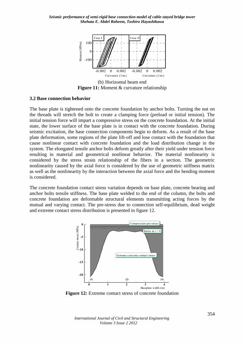
(b) Horizontal beam end
Figure 11: Moment & curvature relationship
3.2 Base connection behavior
The base plate is tightened onto the concrete foundation by anchor bolts. Turning the nut on
the threads will stretch the bolt to create a clamping force (preload or initial tension). The
initial tension force will impart a compressive stress on the concrete foundation. At the initial
state, the lower surface of the base plate is in contact with the concrete foundation. During
seismic excitation, the base connection components begin to deform. As a result of the base
plate deformation, some regions of the plate lift-off and lose contact with the foundation that
cause nonlinear contact with concrete foundation and the load distribution change in the
system. The elongated tensile anchor bolts deform greatly after their yield under tension force
resulting in material and geometrical nonlinear behavior. The material nonlinearity is
considered by the stress strain relationship of the fibers in a section. The geometric
nonlinearity caused by the axial force is considered by the use of geometric stiffness matrix
as well as the nonlinearity by the interaction between the axial force and the bending moment
is considered.
The concrete foundation contact stress variation depends on base plate, concrete bearing and
anchor bolts tensile stiffness. The base plate welded to the end of the column, the bolts and
concrete foundation are deformable structural elements transmitting acting forces by the
mutual and varying contact. The pre-stress due to connection self-equilibrium, dead weight
and extreme contact stress distribution is presented in figure 12.
0 1 2 3 4
-20
-15
-10
-5
0
Extreme concrete contact stress
Compression pre-stress
Stress at t = 0
Baseplate width (m)
Conta
ct s
tres
s (M
Pa)
(1) (2) (3)
Figure 12: Extreme contact stress of concrete foundation
Seismic performance of semi-rigid base connection model of cable-stayed bridge tower
Shehata E. Abdel Raheem, Toshiro Hayashikawa
International Journal of Civil and Structural Engineering
Volume 3 Issue 2 2012
355
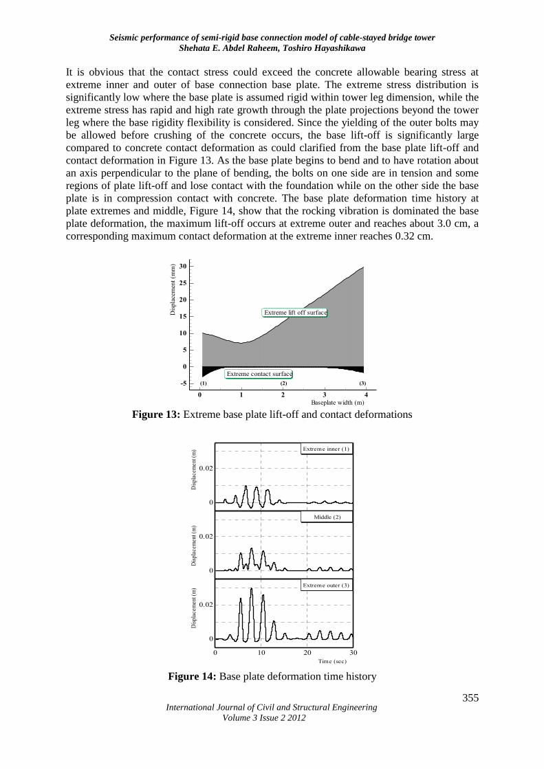
It is obvious that the contact stress could exceed the concrete allowable bearing stress at
extreme inner and outer of base connection base plate. The extreme stress distribution is
significantly low where the base plate is assumed rigid within tower leg dimension, while the
extreme stress has rapid and high rate growth through the plate projections beyond the tower
leg where the base rigidity flexibility is considered. Since the yielding of the outer bolts may
be allowed before crushing of the concrete occurs, the base lift-off is significantly large
compared to concrete contact deformation as could clarified from the base plate lift-off and
contact deformation in Figure 13. As the base plate begins to bend and to have rotation about
an axis perpendicular to the plane of bending, the bolts on one side are in tension and some
regions of plate lift-off and lose contact with the foundation while on the other side the base
plate is in compression contact with concrete. The base plate deformation time history at
plate extremes and middle, Figure 14, show that the rocking vibration is dominated the base
plate deformation, the maximum lift-off occurs at extreme outer and reaches about 3.0 cm, a
corresponding maximum contact deformation at the extreme inner reaches 0.32 cm.
0 1 2 3 4
-5
0
5
10
15
20
25
30
Baseplate width (m)
Dis
pla
cem
ent
(mm
)
Extreme lift off surface
Extreme contact surface
(1) (2) (3)
Figure 13: Extreme base plate lift-off and contact deformations
0
0.02
Dis
plac
emen
t (m
) Extreme inner (1)
0
0.02
Dis
plac
emen
t (m
)
Middle (2)
0 10 20 30
0
0.02
Dis
plac
emen
t (m
)
Time (sec)
Extreme outer (3)
Figure 14: Base plate deformation time history
Seismic performance of semi-rigid base connection model of cable-stayed bridge tower
Shehata E. Abdel Raheem, Toshiro Hayashikawa
International Journal of Civil and Structural Engineering
Volume 3 Issue 2 2012
356
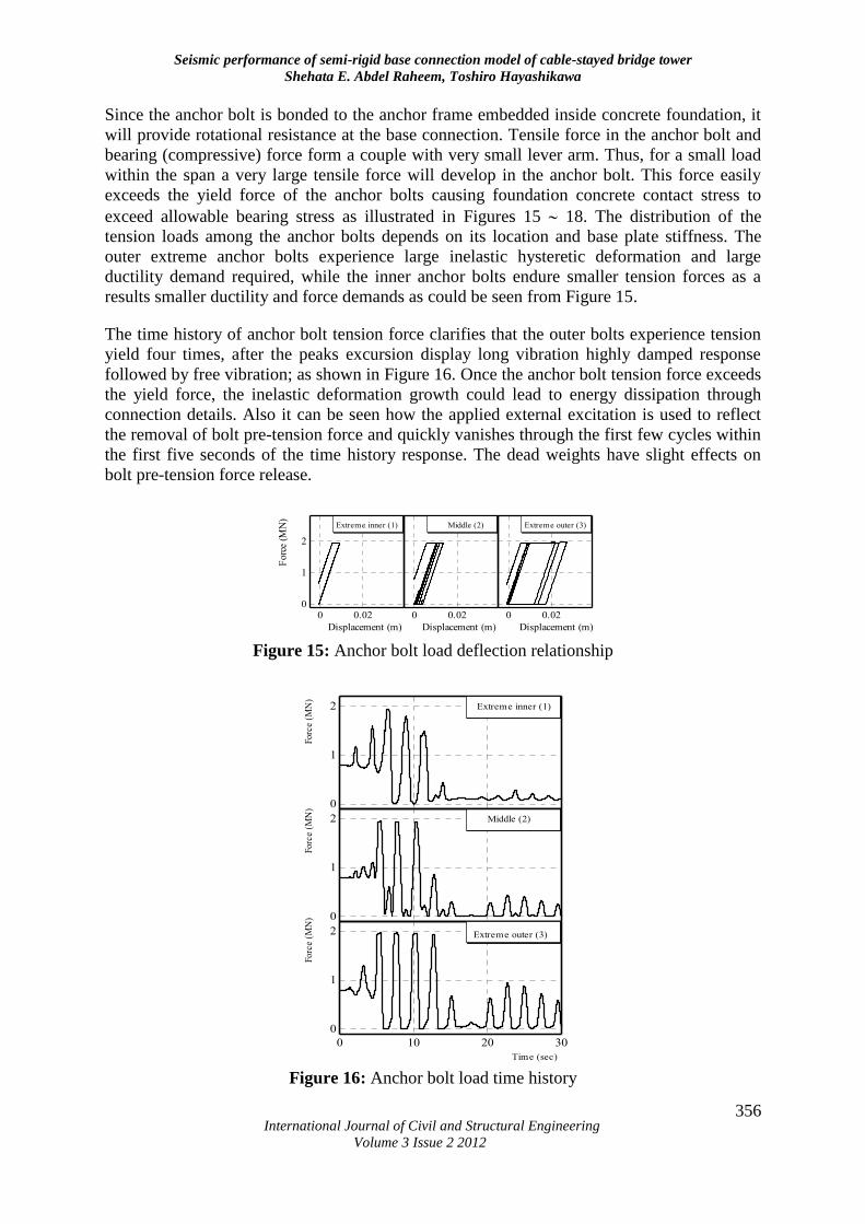
Since the anchor bolt is bonded to the anchor frame embedded inside concrete foundation, it
will provide rotational resistance at the base connection. Tensile force in the anchor bolt and
bearing (compressive) force form a couple with very small lever arm. Thus, for a small load
within the span a very large tensile force will develop in the anchor bolt. This force easily
exceeds the yield force of the anchor bolts causing foundation concrete contact stress to
exceed allowable bearing stress as illustrated in Figures 15 18. The distribution of the
tension loads among the anchor bolts depends on its location and base plate stiffness. The
outer extreme anchor bolts experience large inelastic hysteretic deformation and large
ductility demand required, while the inner anchor bolts endure smaller tension forces as a
results smaller ductility and force demands as could be seen from Figure 15.
The time history of anchor bolt tension force clarifies that the outer bolts experience tension
yield four times, after the peaks excursion display long vibration highly damped response
followed by free vibration; as shown in Figure 16. Once the anchor bolt tension force exceeds
the yield force, the inelastic deformation growth could lead to energy dissipation through
connection details. Also it can be seen how the applied external excitation is used to reflect
the removal of bolt pre-tension force and quickly vanishes through the first few cycles within
the first five seconds of the time history response. The dead weights have slight effects on
bolt pre-tension force release.
0 0.02
Displacement (m)
Middle (2)
0 0.020
1
2
Forc
e (M
N)
Displacement (m)
Extreme inner (1)
0 0.02
Displacement (m)
Extreme outer (3)
Figure 15: Anchor bolt load deflection relationship
0
1
2
Forc
e (M
N)
Middle (2)
0
1
2
Forc
e (M
N)
Extreme inner (1)
0 10 20 30
0
1
2
Forc
e (M
N)
Time (sec)
Extreme outer (3)
Figure 16: Anchor bolt load time history
Seismic performance of semi-rigid base connection model of cable-stayed bridge tower
Shehata E. Abdel Raheem, Toshiro Hayashikawa
International Journal of Civil and Structural Engineering
Volume 3 Issue 2 2012
357
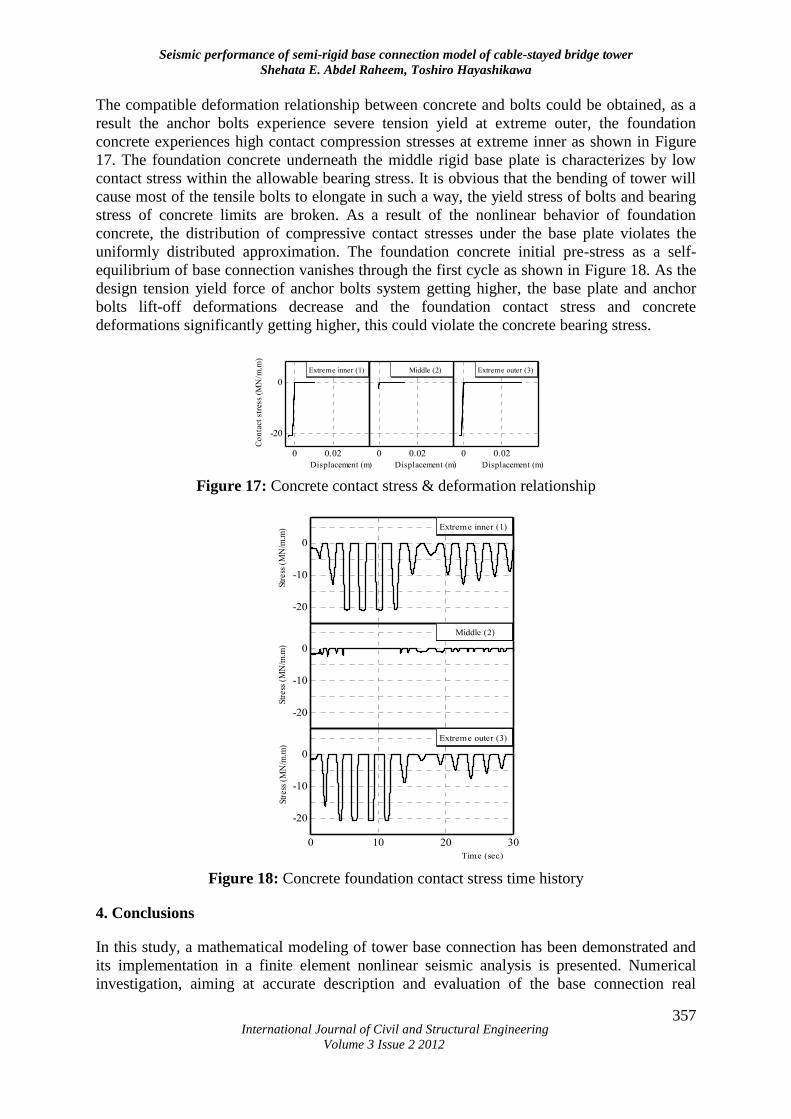
The compatible deformation relationship between concrete and bolts could be obtained, as a
result the anchor bolts experience severe tension yield at extreme outer, the foundation
concrete experiences high contact compression stresses at extreme inner as shown in Figure
17. The foundation concrete underneath the middle rigid base plate is characterizes by low
contact stress within the allowable bearing stress. It is obvious that the bending of tower will
cause most of the tensile bolts to elongate in such a way, the yield stress of bolts and bearing
stress of concrete limits are broken. As a result of the nonlinear behavior of foundation
concrete, the distribution of compressive contact stresses under the base plate violates the
uniformly distributed approximation. The foundation concrete initial pre-stress as a self-
equilibrium of base connection vanishes through the first cycle as shown in Figure 18. As the
design tension yield force of anchor bolts system getting higher, the base plate and anchor
bolts lift-off deformations decrease and the foundation contact stress and concrete
deformations significantly getting higher, this could violate the concrete bearing stress.
0 0.02
-20
0
Co
nta
ct s
tres
s (M
N/m
.m)
Displacement (m)
Extreme inner (1)
0 0.02
Displacement (m)
Middle (2)
0 0.02
Displacement (m)
Extreme outer (3)
Figure 17: Concrete contact stress & deformation relationship
-20
-10
0
Str
ess
(M
N/m
.m) Extreme inner (1)
-20
-10
0
Str
ess
(M
N/m
.m)
Middle (2)
0 10 20 30
-20
-10
0
Str
ess
(M
N/m
.m)
Time (sec)
Extreme outer (3)
Figure 18: Concrete foundation contact stress time history
4. Conclusions
In this study, a mathematical modeling of tower base connection has been demonstrated and
its implementation in a finite element nonlinear seismic analysis is presented. Numerical
investigation, aiming at accurate description and evaluation of the base connection real
Seismic performance of semi-rigid base connection model of cable-stayed bridge tower
Shehata E. Abdel Raheem, Toshiro Hayashikawa
International Journal of Civil and Structural Engineering
Volume 3 Issue 2 2012
358
behavior and its effects on the tower global response has been conducted. The model contains
all the essential features including base plate elasto-plastic behavior, concrete foundation
contact and material nonlinearity and anchor bolt constitutive tension deformation without
contribution in compression that characterize the base connection. The interface between the
base plate and concrete foundation is modeled using contact elements. The bolts are
represented with a group of elements reflecting the characteristics of real bolt behavior in an
efficient manner.
The semi-rigidity of base connections influences the moments and forces distribution as well
as drift of tower frame structure. The fixed base model analysis displays a wide spread of
inelastic deformation through tower structural elements and large ductility demands, which
could lead to over conservative design. The distribution of the tension loads among the
anchor bolts depends on its location and base plate stiffness, the outer extreme anchor bolts
experience large inelastic hysteretic deformations and large ductility demands. The bolt pre-
tension force quickly vanishes through the first few cycles within the first five seconds of the
time history response. The dead weights have slight effects on bolt pre-tension force release.
The base lift-off is significantly large compared to concrete contact deformation; the
distribution of compressive contact stresses under the base plate violates the uniformly
distributed approximation. As the design tension yield force of anchor bolts system getting
higher, the base plate and anchor bolts lift-off deformations decrease, and the foundation
contact stress and concrete deformations significantly getting higher, this could violate the
concrete bearing stress.
References
1. Astaneh-Asl A., Bolt B., McMullin K., Donikian R.R., Modjtahedi D. and Cho S.W.,
(1994), Seismic Performance of Steel Bridges During the 1994 Northridge Earthquake,
Report No. UCB/CEE-Steel-94/01, University of California, Berkeley.
2. Colson A., (1991), Theoretical modelling of semi rigid connections behaviour, Journal of
constructional steel research, 19, pp 213-224.
3. Committee of Earthquake Engineering, (1996), The 1995 Hyogoken-Nanbu Earthquake,
Investigation into damage to civil engineering structures, Japan society of civil engineers.
4. Ermopoulos J. and Michaltsos G., (1998), Analytical modelling of stress distribution
under column base plates, Journal of constructional steel research, 46(1-3), p 136.
5. Ermopoulos J. and Stamatopoulos G., (1996), Analytical modelling of column base plates
under cyclic loading, Journal of constructional steel research, 40(3), pp 225-238.
6. Ermopoulos J. and Stamatopoulos G., (1996), Mathematical modelling of column base
plate connections, Journal of constructional steel research, 36(2), pp 79-100.
7. Jaspart J.P. and Vadegans D., (1998), Application of component method to column bases,
Journal of constructional steel research, 48, pp 89-106.
8. Krishnamurthy N. and Thambirathnam D., (1990), Finite element analysis of column base
plates, Computers & structures, 34, pp 215-223.
Seismic performance of semi-rigid base connection model of cable-stayed bridge tower
Shehata E. Abdel Raheem, Toshiro Hayashikawa
International Journal of Civil and Structural Engineering
Volume 3 Issue 2 2012
359
9. Nakashima S., (1998), Mechanical characteristics of exposed portions of anchor bolts in
steel column bases under combined tension and shear, Journal of constructional steel
research, 46(1-3), pp 262-263.
10. Nakashima S., Kadoya H. and Igarashi S., (1995), A report concerning damage to steel
structures caused by the Hanshin Earthquake of January 17, 1995 in Japan - as to steel
column bases and connections, Nordic steel construction conference 1995, II, Sweden:
Malmo, pp 835-842.
11. Northridge Reconnaissance Team, (1996), Northridge earthquake of January 17, 1994,
Reconnaissance Report, EERI, Oakland, California, pp 25-47.
12. Piluso V. and Faella C., (2001), Ultimate behavior of bolted T-stubs, I: Theoretical
model, Journal of structural engineering, 127(6), pp 686-693.
13. Popov E.P. and Takhirov S.M., (2002), Bolted large seismic steel-to-column connection
part 1: experimental study, Engineering structures, 24, pp 1523-1534.
14. Rothert H., Gebbeken N. and Binder B., (1992), Non-linear three-dimensional finite
element contact analysis of bolted connections in steel frames, International journal for
numerical methods in engineering, 34, pp 303-318.
15. Swanson J.A. and Leon R.T., (2001), Stiffness modeling of bolted T-stub connection
components, Journal of structural engineering, 27(5), pp 498-505.
16. Targowski R., Lamblin D. and Guerlement G., (1993), Base plate column connection
under bending: experimental and numerical study, Journal of constructional steel
research, 27, pp 37-54.
17. Wald F., (1993), Column-base connections, a comprehensive state-of-the art review,
Prague
18. Yang H.T. and Godfrey D.A., (1969), A non-linear analysis of the rotational stiffness of a
nuclear steam generator foundation, Nuclear Engineering and Design, 10, pp 339-348.


![Seismic Performance of Semi-Rigid Connected Prefabricated ... · structures [1]. For this reason, the seismic safety of prefabricated structures presents very common a subject for](https://img.pdfslide.net/doc/110x75/5ede5c76ad6a402d6669af19/seismic-performance-of-semi-rigid-connected-prefabricated-structures-1-for.jpg)