Embed Size (px)
Citation preview

EARTHQUAKE ENGINEERING AND STRUCTURAL DYNAMICS, VOL. 26, 759—777 (1997)
SEISMIC TESTING OF A BUILDING STRUCTURE WITH ASEMI-ACTIVE FLUID DAMPER CONTROL SYSTEM
MICHAEL D. SYMANS1* AND MICHAEL C. CONSTANTINOU2
1Department of Civil & Environmental Engineering, Washington State University, Pullman, WA 99164, U.S.A.2Department of Civil Engineering, State University of New York at Buffalo, Buffalo, NY 14260, U.S.A.
SUMMARY
This paper describes shaking table tests of a multi-storey scale-model building structure subjected to seismic excitationand controlled by a semi-active fluid damper control system. The semi-active dampers were installed in the lateralbracing of the structure and the mechanical properties of the dampers were modified according to control algorithmswhich utilized the measured response of the structure. A simplified time-delay compensation method was developed toaccount for delays within the control system. The results of the shaking table tests are presented and interpreted andanalytical predictions are shown to compare reasonably well with the experimental results. ( 1997 by John Wiley& Sons, Ltd.
Earthquake Engng. Struct. Dyn., 26, 759—777 (1997)
No. of Figures: 10. No. of Tables: 2. No. of References: 28.
KEY WORDS: fluid damper; damping; energy dissipation; structural control; semi-active control; scale-model testing
1. INTRODUCTION
A compromise between passive and active seismic response control systems has been developed recently inthe form of semi-active control systems. Semi-active control systems maintain the reliability of passivecontrol systems while taking advantage of the adjustability of an active control system. The three classes ofcontrol systems may be defined as follows. Passive control systems do not require an external power sourcefor operation and utilize the motion of the structure to develop the control forces. Control forces aredeveloped as a function of the response of the structure at the location of the passive control system. Activecontrol systems require a large power source for operation of electrohydraulic actuators which supply controlforces to the structure. Control forces are developed based on feedback from sensors that measure theexcitation and/or the response of the structure. The feedback from the structural response may be measuredat locations remote from the location of the active control system. Semi-active control systems typicallyrequire a small external power source for operation and utilize the motion of the structure to develop thecontrol forces. Control forces are developed based on feedback from sensors that measure the excitationand/or the response of the structure. The feedback from the structural response may be measured at locationsremote from the location of the semi-active control system.
Semi-active control systems have only very recently been considered for applications to large civilstructures. As such, a major portion of the research in this area has been devoted to analytical and numericalstudies in which a number of idealized assumptions are made. For example, both time delays in operation of
* Correspondence to: Michael D. Symans, Department of Civil and Environmental Engineering, Washington State University,Pullman, WA 99164-2910, U.S.A.
Contract grant sponsor: National Center for Earthquake Engineering Research; Contract grant numbers: 93-5120, 94-5103A.Contract grant sponsor: Taylor Devices, Inc.Contract grant sponsor: Moog, lnc.
CCC 0098—8847/97/070759—19$17·50 Received 29 July 1996( 1997 by John Wiley & Sons, Ltd. Revised 6 January 1997

the control system and the complexities of structural systems are often neglected (for example, see References1—7). The validity of such assumptions must be evaluated through experimental research. Recent experi-mental studies on semi-active control systems have been performed by, for example, Feng and Shinozuka8(semi-active sliding friction bearings), Kobori et al.9 (semi-active stiffness control device), Gavin et al.10 andMakris et al.11 (semi-active electrorheological damper), Kawashima et al.12 and Patten et al.13 (semi-activefluid damper), and Spencer et al.14 (semi-active magnetorheological damper). A summary of the operationand behaviour of some of the above-mentioned experimentally tested semi-active control systems is given bySymans and Constantinou.15 To the author’s knowledge, there are currently (January 1997) no full-scaleapplications of semi-active control systems for seismic protection. However, it is also apparent that suchapplications may be realized prior to the end of this century.
With respect to the research described herein on semi-active fluid damper control systems, the work ofKawashima et al.12 and Patten et al.13 is most directly related. The device tested by Kawashima et al.12consisted of a fluid damper combined with an external bypass loop containing a servovalve. The behaviour ofthe device is controlled by varying the amount of fluid passing through the bypass loop. The device behavesessentially as an adjustable force device with hysteretic-type damping. The semi-active fluid damper tested byPatten et al.13 also consisted of a fluid damper combined with an external bypass loop containing a controlvalve. The intrinsic behaviour of the tested damper is nonlinear. However, the device is made to behave asa linear viscous damper through appropriate adjustment of the control valve.
2. DESCRIPTION OF TESTED SEMI-ACTIVE DAMPERS
The semi-active fluid dampers described in this paper are based on the design of a passive fluid dampingdevice which has been studied for applications in seismic energy dissipation16,17 and seismic isolation18 (seeFigure 1). The passive portion of the semi-active fluid damper consists of a stainless steel piston rod, a bronzepiston head, a piston rod make-up accumulator and is filled with a thin silicone oil. The piston head orificesare designed such that the fluid flow is altered according to the fluid speed resulting in a force output which isproportional to the relative velocity of the piston head with respect to the damper housing. The damper
Figure 1. Construction of tested semi-active fluid damper
760 M. D. SYMANS AND M. C. CONSTANTINOU
Earthquake Engng. Struct. Dyn., 26, 759—777 (1997) ( 1997 by John Wiley & Sons, Ltd.

Figure 2. Response of semi-active damper when subjected to sinusoidal motion and with damping incrementally modified from high tolow
weighed 61·6N, had a fully compressed length of 192 mm, a housing diameter of 63·5 mm, and a maximumoutput force of 8900 N.
The passive fluid damper was modified to create a semi-active damper by including an external bypassloop containing a control valve (see Figure 1). The control valve is a normally closed direct-drive servovalvewhich was originally developed for control of the primary flight control servo-actuation system on the U.S.Air Force B-2 Stealth Bomber. The valve was designed to replace the conventional hydraulic amplifier pilotstage with a drive motor acting directly on the valve spool, eliminating the need for a source of hydraulicpressure to operate the pilot stage. The direct-drive servovalve offers fail-safe characteristics in that the loss ofpower causes the valve to become fully closed which in turn causes the semi-active damper to behave asa passive device with high damping characteristics. Furthermore, the servovalve requires a peak power of3·5 W and can therefore operate on the power of batteries which is critical during an earthquake when theprimary power source of a structure may fail.
The tested semi-active dampers behave essentially as linear viscous dampers with an adjustable dampingcoefficient and are capable of delivering a wide range of damping levels between an upper (valve closed) andlower (valve fully open) bound. This behaviour is demonstrated in Figure 2 which shows the damperresponse when subjected to sinusoidal motion at a frequency of 1 Hz and an amplitude of 25 mm and withthe control valve initially closed and then incrementally opened throughout the test. The elliptical shape ofthe force—displacement loops is a clear indication of linear viscous behaviour. It is important to realize thatthe semi-active damper behaves as an adjustable parameter device rather than an adjustable force device.The interested reader is referred to Reference 15 for a detailed description of the testing and modelling of thesemi-active fluid damper system.
3. DESCRIPTION OF TEST SET-UP FOR SEISMIC SIMULATIONS
A three-storey model structure was used for seismic simulation testing. The structure was a 1 :4 scale steelmoment-resisting frame which modelled a shear building by the method of artificial mass simulation.19 Themodel did not represent a similitude-scaled replica of a full-scale building. Rather, the test structure wasdesigned as a small structural system. The structure was bolted to the shaking table such that the main framesof the model were parallel to the motion of the table. The two frames of the structure which wereperpendicular to the direction of motion were rigidly braced for all tests and ensured that there was nomotion of the structure perpendicular to the direction of table motion. This resulted in the reduction ofa three-dimensional structural system to, essentially, a planar frame. The mass of the three-storey structurewas 2868 kg, each floor having an equal mass of 956 kg. The structure was tested with no dampers (bareframe) and with two semi-active dampers placed within the diagonal bracing of the first storey (see Figure 3).
SEISMIC TESTING OF A BUILDING STRUCTURE 761
( 1997 by John Wiley & Sons, Ltd. Earthquake Engng. Struct. Dyn., 26, 759—777 (1997)

Figure 3. Shaking table test configurations for scale-model structure
Table I. Summary of experimentally identified properties of three-storey structure
Bare frameSemi-active dampers:
low dampingSemi-active dampers:
high damping
Mode 1 2 3 1 2 3 1 2 3Frequency (Hz) 1·80 5·80 11·40 1·80 5·84 11·43 1·85 6·04 11·48
Damping ratio (%) 1·74 0·76 0·34 4·13 3·90 1·07 14·41 18·79 4·83Mode shapes Floor 3 1·00 1·00 1·00
Floor 2 0·83 !0·43 !2·12Floor 1 0·51 !1·28 1·49
The characteristics of the structure were identified using banded white noise (0—20Hz) as input to the shakingtable. The identification procedure is described in detail by Symans and Constantinou.15 A summary of theidentified properties of the model structure with and without semi-active dampers is provided in Table I.
Four different motions were used as input to the shaking table. Two of the motions were historicalearthquake records (1940 El Centro earthquake (component S00E) and 1968 Hachinohe earthquake(component NS)). The historical earthquake records were compressed in time by a factor of two to satisfy thesimilitude requirements of the quarter-length scale model. The two other motions were a high-frequencyversion of the historical Hachinohe earthquake record and a harmonic signal of constant frequency andamplitude. In order to excite the test structure with earthquake motions of different intensity, the amplitudeof the earthquake records was scaled for many of the shaking table tests.
A number of sensors were utilized to measure the response of the structure (absolute acceleration anddisplacement at each floor level) and the motion of the table (acceleration and displacement). A displacementtransducer located along the axis of each damper measured the displacement of the piston rod with respect tothe damper housing. Velocity measurements were obtained by passing displacement signals throughanalogue differentiators.
A block diagram showing the closed-loop shaking table tests with the semi-active dampers is provided inFigure 4. Both a data acquisition computer and a control computer were used during the tests. The control
762 M. D. SYMANS AND M. C. CONSTANTINOU
Earthquake Engng. Struct. Dyn., 26, 759—777 (1997) ( 1997 by John Wiley & Sons, Ltd.

Figure 4. Block diagram of closed-loop shaking table tests with semi-active dampers
computer received signals from the measure response of the structure, processed the signals according toa pre-determined control algorithm, and sent an appropriate command signal to the semi-active dampervalves. The response measurements were passed through six-pole low-pass Butterworth filters (cut-offfrequency"25 Hz) prior to entering the control computer. The control algorithms utilized for operation ofthe semi-active dampers were implemented on a PC computer with an INTELTM 80386/25 MHz processorwith two 12 bit data acquisition boards. Computer programs were written in the Microsoft QuickBASICcomputer language (extended version 7.1) for implementation of the control algorithms. The sampling ratefor control of the dampers was dependent on the control algorithm and ranged from about 160 pt/sec toabout 530 pt/sec.
4. CONTROL ALGORITHMS FOR SEISMIC SIMULATION TESTING
As described in Section 2, the tested semi-active fluid dampers behave essentially as linear viscous damperswith an adjustable damping coefficient as given by the following expression
P (t)"CSA
uR (t); C.*/
)CSA)C
.!9(1)
where P (t) is the force in the damper, uR (t) is the relative velocity of the damper piston head with respect to thedamper housing, C
SAis the adjustable damping coefficient, and C
.*/and C
.!9are the lower and upper
bound, respectively, on the adjustable damping coefficient. Control algorithms in which the constraint on thedamping coefficient was not directly taken into account were developed. Rather, during experimentalapplication of the control algorithms, the damping coefficient was clipped at the upper and lower bounds. Ingeneral, the control algorithms for the dampers may require that the dampers perform work on the structuresuch that the energy within the structural system is increased. The effect of clipping the damping coefficient at
SEISMIC TESTING OF A BUILDING STRUCTURE 763
( 1997 by John Wiley & Sons, Ltd. Earthquake Engng. Struct. Dyn., 26, 759—777 (1997)

Figure 5. Relationship between experimental values of damping coefficient and command signal for semi-active dampers
the lower bound is to account for the inability of the semi-active dampers to perform this type of work on thestructure (i.e. the dampers are only capable of absorbing energy). The issue of stability was not explicitlyconsidered in the development of the control algorithms since the semi-active fluid dampers can only absorbenergy; they are not capable of storing energy and thus inducing instability.
The relationship between the semi-active damper command signal and the damping coefficient is shown inFigure 5 for both sinusoidal and constant velocity cyclic testing over a range of frequencies from 0·25 to 4 Hz.The scatter in the data is primarily related to the frequency of testing. For semi-active damper commandvoltage levels between 0·75 and 2·25 V, the damping coefficient can be estimated by fitting a linear curvethrough the experimental data. In the control algorithms described in the following sections, the objective isto determine the damping coefficient which satisfies a given control objective and, based on the linearapproximation shown in Figure 5, the appropriate command voltage is determined. The three storeystructure was tested with two different control algorithms, one based on optimal control theory and the otherbased on sliding mode control theory.
4.1. Optimal control algorithm
The Linear Quadratic Regulator (LQR) optimal control algorithm has been investigated by a number ofresearchers for application to semi-actively controlled structures (e.g. see References 1, 2, 4, 13, and 20) and toactively controlled structures (e.g. see References 21 and 22). The general optimal control problem may bestated as follows: given a system subjected to external inputs, find the control which minimizes a certainmeasure of the performance of the system. The performance index for the LQR problem is given by thefollowing scalar quantity:
J"Pt&
0
(MZNT [Q] MZN#MdNT [R] MdN) dt (2)
where t&is the final time of the control interval, MZN is the state vector, MdN is the control force vector, [Q] is
a positive semi-definite state weighting matrix, and [R] is a positive-definite control force weighting matrix.The relative values assigned to the state and control weighting matrices reflect the importance attached tominimization of the state variables and control forces, respectively. The optimal control problem involves theminimization of the scalar functional J subject to the constraint equation given by the equation of motion ofthe system. The minimization process leads to the following control force vector:
MdN"!12[R]~1 [B]T [P] MZN"[G] MZN (3)
764 M. D. SYMANS AND M. C. CONSTANTINOU
Earthquake Engng. Struct. Dyn., 26, 759—777 (1997) ( 1997 by John Wiley & Sons, Ltd.

where [G] is a constant control gain matrix, [B] is the control force location matrix, and [P] is the so-calledRicatti matrix which is obtained from the solution of the algebraic matrix Ricatti equation.22 Note that toarrive at the control force vector described by equation (3), the earthquake input must be neglected. Further,it is important to realize that in both experimental and analytical studies, the values assigned to the weightingmatrices are typically obtained through parametric studies that include the seismic excitation.
The three-storey model structure was tested with semi-active dampers in the first storey only. In this case,the control force vector of equation (3) becomes a scalar quantity given by
d"3+n/1
(g1,n
un)#
3+n/1
(g1,n`3
uRn) (4)
where gi, j
is the component of matrix [G] in the ith row and the jth column and unand uR
nare the relative
displacement and relative velocity, respectively, of the nth floor. To facilitate comparison of results withprevious work, the state and control force weighting matrices were selected to be identical to those used byprevious researchers21,22 in the study of an active tendon system on the same three-storey model structure.The algebraic matrix Ricatti equation was solved to obtain the Ricatti matrix, [P], which was thensubstituted into equation (3) to obtain the 1]6 control gain matrix (g (1, 1)"2316·2 N/cm, g (1, 2)"!1638·4 N/cm, g(1, 3)"471·1 N/cm, g (1, 4)"205·8N s/cm, g(1, 5)"23·2N s/cm, g (1, 6)"60·3 N s/cm).Assuming that the semi-active dampers behave according to a linear viscous dashpot model, accounting forthe angle of inclination of the dampers, and recognizing the constraint on the damping coefficient given byequation (1), the necessary variation in the damping coefficient of each semi-active damper is given by
CSA"G
C.*/
if C*)C.*/
(g cos2 huR1)~1C
3+n/1
(g1,n
un)#
3+n/1
(g1,n`3
uRn)D , if C
.*/)C*)C
.!9
C.!9
if C**C.!9
(5)
where
C*"1
g cos2 huR1C
3+n/1
(g1,n
un)#
3+n/1
(g1,n`3
uRn)D (6)
and g is the number of dampers and h is the angle of inclination of the dampers. Note that equation (5) isconsidered to be a suboptimal damping coefficient since the damping coefficient constraint equation(equation (1)) was not considered in the optimization process.
4.2. Sliding mode control
The objective of the control algorithm described in this section is to track a specified trajectory,and in particular, for the case of stabilization the desired trajectory is identically zero. The combinederror in velocity and displacement is used to determine the accuracy of tracking. Moreover, the algorithmcan accommodate uncertainties that may exist in the parameters that define the structural system(e.g. mass, stiffness, and damping properties). The control algorithm is developed based on sliding modecontrol theory. A major advantage of sliding mode control theory is that the control of the structural systemcan be designed to be robust with respect to unmodelled dynamics, uncertain parameters, and externalinputs. Sliding mode control theory begins with the design of a switching surface so that the response of thestructural system has certain prescribed characteristics on the surface (e.g. the design is such that the system isasymptotically stable on the surface). Following the design of the switching surface, a control strategy is
SEISMIC TESTING OF A BUILDING STRUCTURE 765
( 1997 by John Wiley & Sons, Ltd. Earthquake Engng. Struct. Dyn., 26, 759—777 (1997)

developed which directs the response of the structural system onto the switching surface and attempts tomaintain it there.
The sliding mode control algorithm utilized herein has been described by Ghanem and Bujakov23 forapplications to the control of Single-Degree-of-Freedom (SDOF) systems with uncertain parameters. Theapproach for SDOF systems was modified to adapt the algorithm for control of the three-storey modelstructure. Specifically, the three-storey structure was modelled as an equivalent SDOF structure which hasthe same natural frequency as the fundamental mode of the three-storey structure and the same base shearand overturning moment. A detailed description of the sliding mode control algorithm as used in this study isprovided by Symans and Constantinou.15
5. SYSTEM TIME DELAYS AND METHODS OF COMPENSATION
There is a considerable amount of analytical research performed in the area of active and semi-activestructural control in which the measurement of the response of the structure, the control computation, andthe application of the control force are assumed to occur instantaneously. However, as a number ofexperimental studies have shown, time delays exist in the control system and, in general, must be consideredto ensure stability of the structural system. Many methods of time delay compensation have been developedand experimentally tested (e.g. see References 22, 24, and 25).
Time delays may be conveniently separated into two components. In the following, it is assumedthat the application of structural control is based on feedback that includes the response quantityR(t) (e.g. displacement, velocity, acceleration, etc.). The first portion of the time delay is designatedas q
1and represents the time required to obtain measurements of the response. The second portion
of the time delay is designated as q2
and represents the time required to apply the desired controlforce. At time t, the control computer determines the response of the structural system. Ideally, the measuredresponse is R(t). However the measured response actually occurred at time t
1where the response is R(t
1) and
is being measured with a time delay due to, for example, signal conditioners, filters, differentiators,integrators, and computer computations. Also, at time t, the control computer determines the appropriatecontrol signal to be sent to the control system. Ideally, the control is applied at time t. However, the controlsystem does not respond instantaneously and actually applies the control force at time t
2where the response
is R(t2). Clearly, if time delays are not considered, control forces will be applied at time t
2based on the
response at time t1.
The approach used herein to account for time delays is as follows: at time t, the controller receivesinformation on the response measured at time t
1and uses this information to predict the response at time t
2.
The predicted response is based on experimentally measured values of time delays q1
and q2. Further, the
predicted response is used to determine the appropriate control force to be applied at time t2. Note that time
delay compensation was employed only for tests in which the optimal control algorithm was utilized. Testswere performed without time delay compensation using both the optimal control algorithm and the slidingmode control algorithm.
5.1. Harmonic time delay compensation
The harmonic time delay compensation method is a simplified method which was developed by theauthors and is based on the assumption that the structure responds as an undamped system in free vibrationduring the time interval between measuring the response and applying the control force. Clearly, thisassumption is incorrect since the ground motion as well as the semi-active damper control forces act on thesystem during this time interval. However, if time delays are relatively small, the assumption of harmonicmotion may be acceptable. Consider the relative displacement response vector of a Multi-Degree-of-Freedom (MDOF) structure which may be written in terms of modal coordinates as
MuN"['] MyN (7)
766 M. D. SYMANS AND M. C. CONSTANTINOU
Earthquake Engng. Struct. Dyn., 26, 759—777 (1997) ( 1997 by John Wiley & Sons, Ltd.

where MyN is the modal coordinate vector and ['] is the mode shape matrix. Letting t1"0 and t
2"q (i.e.
starting time at t1), the free vibration response of the kth mode may be written as
yk(q)"
yRk(0)
uk
sin (ukq)#y
k(0) cos (u
kq) (8)
where ukis the natural frequency of the kth mode. Note that q is equal to the sum of time delays q
1and q
2.
The relative displacement vector is obtained as the sum of the modal contributions from each mode k:
MuN"N+k/1
M/kN y
k(9)
where N is the number of modes and M/kN is the mode shape corresponding to the kth mode. At time t"0,
the value of the modal coordinate vector and its derivative can be obtained from equation (7). Combining theresulting expressions with equations (8) and (9), we obtain the predicted relative displacement of the jthdegree of freedom in the following simple form:
uj(q)"
N+i/1
[(ai)jui(0)#(b
i)juRi(0)] (10)
where ui(0) and uR
i(0) are the relative displacement and relative velocity, respectively, of the ith degree of
freedom at time t"0 and (ai)jand (b
i)jare constants corresponding to the jth degree of freedom and are
determined from the modal frequencies, mode shapes, and measured time delays. Expressions similar toequation (10) can be developed to predict the relative velocity and relative acceleration corresponding to thejth degree of freedom.
5.2. Experimentally measured time delays
The response measurement time delay, q1, and the control force time delay, q
2, were determined from
experimental measurements of various time delays. Time delay q1
is considered to be the result of thefollowing: signal conditioning, filtering, differentiating, and control computer computations. Time delay q
2is
considered to be the result of delays in operation of the semi-active dampers.The time delays associated with response measurement (signal conditioning (0·0 ms), low-pass filtering
(21·0 ms), analog differentiation (3·9 ms)) and control computer computations (1·9—6·3 ms) are obtained bypassing a white noise signal through each component of the system and obtaining the transfer functionbetween the input and output signal. For white noise input, the transfer function between the input andoutput signal at frequency u is given by
¹ (u)"exp (iuq$) (11)
where q$
is the time delay and i is the imaginary unit. The phase angle is given by
h (u)"tan~1AI[¹ (u)]
R[¹ (u)]B"uq$
(12)
where I[f] and R[f] indicate the imaginary and real parts of the contained complex quantity. Therefore, incomponents which exhibit a pure time delay, the amplitude of the transfer function is unity (equation (11))and the phase angle is a linear function of frequency (equation (12)). The time delay is obtained from equation(12) using experimentally measured values of the phase angle.
The time delay associated with the development of the semi-active damper control force was determinedby measuring the system response to a saturated command signal (i.e. a command signal which completelyopens the value or completely closes the valve; thus modifying the damping coefficient from its maximum tominimum value and vice versa). The average time delay associated with modification of the control force was20·3 ms.
SEISMIC TESTING OF A BUILDING STRUCTURE 767
( 1997 by John Wiley & Sons, Ltd. Earthquake Engng. Struct. Dyn., 26, 759—777 (1997)

6. SEISMIC SIMULATION TEST RESULTS
Selected seismic simulation test results are presented in this section. A more detailed presentation of resultsmay be found in Reference 15. The benefits of using a semi-active control system can be assessed in manyways. In this study, a comparison of certain key response parameters are made for the structure with nodampers (bare frame), with two passive dampers (semi-active damper with fixed valve configuration), andwith two semi-active dampers. The effect of the low and high damping passive control systems on thestructure subjected to the El Centro ground motion is shown in Figure 6. The percentage figure shown inFigure 6 indicates the scale factor for the ground acceleration record (i.e. the ground acceleration for Figure 6
Figure 6. Seismic response of three-storey structure with passive damping
768 M. D. SYMANS AND M. C. CONSTANTINOU
Earthquake Engng. Struct. Dyn., 26, 759—777 (1997) ( 1997 by John Wiley & Sons, Ltd.
was scaled in magnitude by a factor of 25 per cent). Recall that the damping ratio in the fundamental modeof the three-storey structure with dampers set to low and set to high damping was about 4 and 14 per cent,respectively (see Table I). Note that friction is clearly present in the low damping test. This friction occursbetween the piston rod and piston rod seal. In the high damping test, the primary source of energy dissipationappears to be through viscous fluid damping. A comparison between the low and high damping response ofFigure 6 reveals that the first storey shear and first storey drift are reduced by factors of 1·5 and 1·8,respectively. Similar reductions are obtained in the second and third stories. The large increase in dampingwas clearly beneficial to the structure for this particular input. For the semi-active control algorithmsemployed in this study, the response reduction achieved by the semi-active control system was, in general,comparable to that afforded by the high damping passive control system.
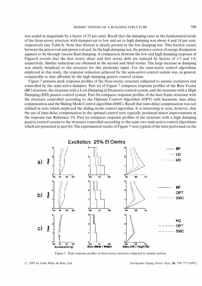
Figure 7 presents peak response profiles of the three-storey structure subjected to seismic excitation andcontrolled by the semi-active dampers. Part (a) of Figure 7 compares response profiles of the Bare Frame(BF) structure, the structure with a Low Damping (LD) passive control system, and the structure with a HighDamping (HD) passive control system. Part (b) compares response profiles of the bare frame structure withthe structure controlled according to the Optimal Control Algorithm (OPT) with harmonic time delaycompensation and the Sliding Mode Control algorithm (SMC). Recall that time-delay compensation was notutilized in tests which employed the sliding mode control algorithm. It is interesting to note, however, thatthe use of time-delay compensation in the optimal control tests typically produced minor improvements inthe response (see Reference 15). Part (c) compares response profiles of the structure with a high dampingpassive control system to the structure controlled according to the same two semi-active control algorithmswhich are presented in part (b). The experimental results of Figure 7 were typical of the tests performed on the
Figure 7. Peak response profiles of three-storey structure subjected to seismic motion
SEISMIC TESTING OF A BUILDING STRUCTURE 769
( 1997 by John Wiley & Sons, Ltd. Earthquake Engng. Struct. Dyn., 26, 759—777 (1997)

three-storey structure subjected to earthquake input (recall that a more detailed presentation of theexperimental results is given in Reference 15) and thus one may conclude that:
(1) The response of the bare frame structure is significantly reduced with the addition of the passive highdamping control system (see part (a) of Figure 7).
(2) The response of the bare frame structure is significantly reduced with the addition of the semi-activecontrol systems (see part (b) of Figure 7).
(3) The response of the structure with the passive high damping control system is typically less than ornearly the same as the response obtained with the semi-active control systems (see part (b) of Figure 7).
Evidently, the use of a semi-active control system offered no significant advantage over the use of a highdamping passive control system. Similar conclusions were made by Polak et al.26 in a numerical study ona three-storey structure with a semi-active damping system. However, the authors of that study note that,under certain special conditions (e.g. at soil sites in which resonances can be expected but the resonantfrequency is difficult to establish), a semi-active damping system may be warranted.
The future implementation of semi-active control systems will require that the systems be robust withrespect to measurement errors. This issue was explored in a test on the three-storey structure subjected to theHachinohe ground motion (see Figure 8). In Figure 8(a), a comparison is made between the passive highdamping control system response and the semi-active control system response using the optimal controlalgorithm without time-delay compensation. As discussed previously, the response of the three-storeystructure with a semi-active control system is nearly the same as the response with a passive high damping
Figure 8. Verification of robust behaviour of three-storey structure with semi-active control system
770 M. D. SYMANS AND M. C. CONSTANTINOU
Earthquake Engng. Struct. Dyn., 26, 759—777 (1997) ( 1997 by John Wiley & Sons, Ltd.

control system. In Figure 8(b), the same comparison is made as in Figure 8(a) except with the second floorabsolute displacement signal disturbed during the semi-active control test (the disturbance was caused byrandomly moving the external magnet assembly of the linear displacement transducer during the shakingtable test). Recall that analogue differentiators are used to obtain the total velocity at each floor level.Therefore, both the second floor displacement and velocity were affected by the disturbance. It is apparentfrom Figure 8(b) that the measurement errors caused by the disturbance did not adversely affect the responseof the structure (maximum peak acceleration increase of about 4 per cent, no increase in peak shear force, anda peak drift increase at the first storey of about 11 per cent). A different disturbance was produced byrandomly adjusting the command signal to the semi-active damper valves during the semi-active control test(see Figure 8(c)). A valve command signal was generated by the control computer but the power supply to thevalve control circuits was turned on and off randomly to allow or not allow, respectively, the valve commandsignal to be sent to the valve. The effect of the random command was to increase peak accelerations and peakshear forces by about 12 per cent and peak drifts by about 28 per cent.
7. ANALYTICAL PREDICTIONS OF SEISMIC SIMULATION TEST RESULTS
Analytical predictions of the shaking table test results were obtained using two different methods. Onemethod assumes that, at each time step in the analysis, the response is measured instantaneously, a commandsignal is determined instantaneously, and the semi-active dampers respond instantaneously. This type ofcontrol is ideal but cannot be realized in the laboratory. The analytical predictions associated with thismethod are designated as ‘instantaneous’ control predictions. A second method for analytical predictionswas developed to take into the account the inherent time delays associated with dynamic control systems.This method assumes that, at each time step in the analysis, the response is measured with a time delay, thecommand signal is generated based on the delayed response, and the semi-active dampers respond with botha static and dynamic time delay (the static time delay corresponds to a period of time after which thecommand signal has been sent to the valve but during which the valve spool does not move). Further, it isassumed that the semi-active control valves are not capable of responding to a command signal if they arecurrently responding to a previous command signal. Analytical predictions were obtained by numericallysolving the set of differential equations describing the system.27 The predictions which include the effect oftime delays generally produced results that are in closer agreement with the experimentally measured resultsthan the predictions obtained under the assumption of instantaneous control.
The equation of motion for the three-storey structure with semi-active dampers is given as follows where itis assumed that the structure behaves as a shear-type building
[M] MuN#[C6] MuR N#[K]MuN#MP
$N"![M] M1N u
'(13)
where [M] is the mass matrix, [C6] is the damping matrix of the bare frame structure, [K] is the stiffness
matrix, MP$N is the control force vector, M1N is a vector of units, u
'is the ground acceleration, and MuN, MuR N and
MuN are the relative acceleration, velocity, and displacement vectors, respectively. For the case of twosemi-active dampers in the first storey, the damper force vector is given by
MP$N"G
0
0
2P1H (14)
where P1
is the horizontal component of damper force in a single damper in the first storey. As mentionedpreviously, the semi-active dampers behave essentially as linear viscous dampers with an adjustable dampingcoefficient. However, as the frequency of motion is increased, the dampers begin to develop stiffness. This canbe accounted for by utilizing a Maxwell fluid model for describing the damper behavior (see Reference 15)
P1#jPQ
1"C
SAcos2 huR
1(15)
SEISMIC TESTING OF A BUILDING STRUCTURE 771
( 1997 by John Wiley & Sons, Ltd. Earthquake Engng. Struct. Dyn., 26, 759—777 (1997)
where j is the relaxation constant. Equations (13)—(15) can be written as a set of first-order differentialequations
MZQ N"[A]MZN#[H]M f N (16)
where
[Z]"GMuR NMuN
MP$NH (17)
[A]"C![M]~1 [C
6]
[I]
j~1[C]
![M]~1 [K]
[0]
[0]
![M]~1
[0]
!j~1[I]D (18)
[H]"C[I]
[0]
[0]D (19)
M f N"M1N u'
(20)
and
[C]"C0 0 0
0 0 0
0 0 2 CSA
cos2 hD (21)
Note that [I] and [0] represent the identity and null matrix, respectively. Analytical predictions for thethree-storey structure were obtained by numerically solving the set of differential equations described byequation (16). The stiffness and damping matrix of the structure, [K] and [C
6] in equation (13), were
obtained from experimentally determined frequencies, damping ratios, and mode shapes. The numericalsolution provides the response history of the quantities in vector MZN (i.e. the relative displacement vector, therelative velocity vector, and the vector of horizontal component of force from the semi-active dampers). Thetotal acceleration vector is computed from equation (16) and is used in calculation of the story shear forces.
Experimental results are compared with analytical predictions in Figure 9 for the three-storey structurewith semi-active dampers subjected to the El Centro ground motion and controlled according to the optimalcontrol algorithm without time-delay compensation. The two different analytical methods previouslydescribed were used to obtain the analytical predictions. In the first method, instantaneous control wasassumed. Although instantaneous control cannot be realized in the laboratory, it does represent the idealresponse for the given semi-active control algorithm. In the second method, experimentally measured timedelays were utilized. The two methods produce very similar results and compare reasonably well with theexperimental results. Of course, the experimentally measured delays for the semi-active dampers wereobtained in saturated command signal tests in which a single command signal was applied to the controlvalve (see Section 5.2 and Reference 15). During the shaking table tests, however, the command signal to thecontrol valves was updated at time intervals of approximately 2—6 ms. Lack of knowledge regarding the
772 M. D. SYMANS AND M. C. CONSTANTINOU
Earthquake Engng. Struct. Dyn., 26, 759—777 (1997) ( 1997 by John Wiley & Sons, Ltd.

Figure 9. Comparison of experimental and analytical response of three-storey structure with a semi-active control system
behaviour of the control valves under such high frequency command signals inhibited the analyticalprediction of experimental results. The analytical predictions may be further improved by developing animproved analytical model for the semi-active damper that explicitly accounts for the dynamics of theservovalve.
8. COMPARISON WITH AN ACTIVE CONTROL SYSTEM
A comparison can be made between the results from the semi-active control tests described in this paper andprevious results obtained from active control tests on the same structure in which an active tendon control
SEISMIC TESTING OF A BUILDING STRUCTURE 773
( 1997 by John Wiley & Sons, Ltd. Earthquake Engng. Struct. Dyn., 26, 759—777 (1997)

Table II. Comparison of properties of three-storey structure used in active and semi-active control tests
System parameters
Frequency (Hz) Damping ratio (%)
Control system Mode 1 Mode 2 Mode 3 Mode 1 Mode 2 Mode 3
Active control tests Bare frame 2·20 6·80 11·50 1·60 0·39 0·36Active tendon 2·28 6·94 11·56 12·77 12·27 5·45
system
Semi-active control Bare frame 1·80 5·80 11·40 1·74 0·76 0·34tests High passive 1·85 6·04 11·48 14·41 18·79 4·83
damping
system was utilized in combination with a linear optimal control algorithm similar to that described inSection 4.1.21,22,28 The properties of the three-storey structure described in this paper are compared inTable II with the properties of the same structure when it was tested using an active control system. Note thatthe dynamic characteristics of the bare frame structure exhibited some small changes during the interimbetween the two testing programs. A comparison of seismic response profiles for the two systems is presentedin Figure 10 for the El Centro ground motion. The percentage figures shown in Figure 10 indicate the peakresponse reduction in comparison with the bare frame structure response. Figure 10(a) shows that the activetendon system significantly reduces the peak response as compared with the bare frame structure. Further,Figure 10(b) shows that the peak response reduction obtained with the high damping passive control systemsurpasses the reduction obtained with the active tendon system. Finally, Figure 10(c) shows results for thesemi-active control system in which the optimal control algorithm without time delay compensation wasutilized. Recalling Section 4.1, the optimal control algorithm used in the semi-active control test of Figure10(c) is identical to that used in the active tendon control test of Figure 10(a) except that, for the semi-activecontrol test, the damping coefficient is bounded according to equation (1). The results of Figures 10(a) and10(c) indicate that the semi-active control system was capable of achieving larger reductions in peak responsein comparison to the active control system in which the same control algorithm was utilized. This was simplythe result of larger effective damping in the semi-active control system. Interestingly, the semi-active controlsystem produced peak response reductions which are nearly identical to those obtained with the highdamping passive control system (compare Figures 10(b) and 10(c)). Apparently, the high damping passivecontrol system was more efficient than the active or semi-active control systems for this particular structure,excitation, and control algorithm.
9. CONCLUSIONS
A small scale model of a moment-resisting frame outfitted with a semi-active control system was tested withseismic ground motion supplied by a large shaking table. The semi-active control system was in the form offluid dampers which were capable of developing a wide range of damping levels between an upper and lowerbound. The results from shaking table tests demonstrated the following:
(1) The response of the structure with no dampers (bare frame) was dramatically improved with theaddition of the semi-active damper control system.
(2) The response reductions achieved with the semi-active control system were comparable to thoseobtained with a high damping passive control system (as measured by peak response quantities). It isexpected that further response reductions beyond those afforded by a passive control system can be
774 M. D. SYMANS AND M. C. CONSTANTINOU
Earthquake Engng. Struct. Dyn., 26, 759—777 (1997) ( 1997 by John Wiley & Sons, Ltd.

Figure 10. Comparison of response of three-storey structure controlled by (a) an active control system, (b) a passive control system, and(c) a semi-active control system
achieved through improved control algorithms (e.g. by incorporating the constraint on the dampingcoefficient), improved semi-active damper hardware, and improved methods of accounting for timedelays either directly through improved modelling of the dynamics of the control system or indirectlythrough improved time-delay compensation methods. In addition, one may easily reduce time delaysassociated with response measurement by utilizing digital filters rather than analogue filters. Further-more, this study was limited to a specific type of structural system which was subjected to a limitedrange of ground motion characteristics. There may be other conditions in which the use of semi-activedampers may prove advantageous.
(3) The use of time delay compensation typically produced minor improvements in the response and, insome cases (not reported herein), degraded the response. The implementation of time delay compensa-tion in a feedback control system requires a good estimate of the time delays associated with eachcomponent of the control system. The time delays associated with response measurements hadwell-defined values. In contrast, the semi-active damper time delays were not as well defined andaverage values from command signal saturation tests were used in the shaking table tests whichemployed time delay compensation. Moreover, the time delay compensation method utilized in thisstudy was based on certain simplifying assumptions and thus was approximate in nature.
SEISMIC TESTING OF A BUILDING STRUCTURE 775
( 1997 by John Wiley & Sons, Ltd. Earthquake Engng. Struct. Dyn., 26, 759—777 (1997)

(4) The semi-active control system was robust with respect to measurement disturbances and commandsignal disturbances in the sense that the structural system did not become unstable as a result of thedisturbances. Stability is generally not a concern in control systems which can only extract energy fromthe structural system. In contrast, the servohydraulic actuators used within active control systems arecapable of supplying energy to the structural system and thus the issue of stability must be addressed.
(5) The semi-active damper control system produced larger response reductions in the three-storeystructure compared to those obtained with an active tendon control system wherein both controlsystems were designed according to optimal control theory. The difference in response of thesemi-active and active control systems was simply the result of larger effective damping in thesemi-active control system.
Finally, the importance of comparing the response of structures with semi-active and active controlsystems to structures with properly designed passive control systems must be stressed. Only then can thebenefits of these technologies be assessed and reported in a form which is useful to the profession.
ACKNOWLEDGEMENTS
Financial support for this work was provided by the National Center for Earthquake Engineering Research(Project Numbers 93-5120 and 94-5103A), Taylor Devices, Inc., N. Tonawanda, NY and Moog Inc., E.Aurora, NY. Furthermore, Taylor Devices, Inc. and Moog Inc. donated equipment which was used duringthe experimental portion of the research project. The assistance and cooperation of Mr. Douglas P. Taylor(President, Taylor Devices, Inc.) and Mr. Kenneth D. Garnjost (Vice President for Engineering, Moog Inc.) isgratefully acknowledged.
REFERENCES
1. D. Hrovat, P. Barak and M. Rabins, ‘Semi-active versus passive or active tuned mass dampers for structural control’, J. eng. mech.,ASCE, 109(3), 691—705 (1983).
2. T. Mizuno, T. Kobori, J. Hirai, M. Yoshinori and N. Niwa, ‘Development of adjustable hydraulic damper for seismic responsecontrol of large structures’, in P»P-»ol. 229, DOE Facilities Programs, Systems Interaction, and Active/Inactive Damping, ASME,New Orleans, LA, June, 1992, pp. 163—170.
3. S. Rakheja and A. K. Ahmed, ‘Simulation of non-linear variable dampers using energy similarity’, Eng. comput. 8, 333—344 (1991).4. K. Hasewaga and J. M. Kelly, ‘Application of a mass damping system to bridge structures’, Report No. ºBC/EERC-92/12,
Earthquake Engineering Research Center, University of California, Berkeley, 1992.5. M. Shinozuka and R. Ghanem, ‘Use of variable dampers for earthquake protection of bridges’, in Proc. 2nd º.S.—Japan workshop on
earthquake protective systems for bridges, Public Works Research Institute, Tsukuba Science City, Japan, December, 1992, pp.507—516.
6. Z. Akbay and H. M. Aktan, ‘Actively regulated friction slip braces’, in Proc. Sixth Canadian conf. on earthquake eng., Toronto,Canada, June, 1991, pp. 367—374.
7. W. N. Patten, R. L. Sack, W. Yen, C. Mo and H. C. Wu, ‘Seismic motion control using semi-active hydraulic force actuators’, in Proc.seminar on seismic isolation, passive energy dissipation, and active control, Report No. A¹C-17-1, Applied Technology Council, SanFrancisco, CA, March, 1993, pp. 727—736.
8. M. Q. Feng and M. Shinozuka, ‘Experimental and analytical study of a hybrid isolation system using friction controllable slidingbearings’, Report No. NCEER 92-0009, National Center for Earthquake Engineering Research, Buffalo, NY, 1992.
9. T. Kobori, M. Takahashi, T. Nasu and N. Niwa, ‘Seismic response controlled structure with active variable stiffness’, EarthquakeEngng. Struct. Dyn., 22, 925—941 (1993).
10. H. P. Gavin, Y. D. Hose and R. D. Hanson, ‘Design and control of electrorheological dampers’, in Proc. 1st world conf. on structuralcontrol, Los Angeles, CA, August, WP3-83—WP3-92, 1994.
11. N. Makris, D. Hill, S. Burton and M. Jordan, ‘Electrorheological fluid damper for seismic protection of structures’, in Proc. smartstructures and materials conf., San Diego, CA, February, 1995, pp. 184—194.
12. K. Kawashima, S. Unjoh, H. Iida and H. Mukai, ‘Effectiveness of the variable damper for reducing seismic response of highwaybridges’, in Proc. 2nd º.S—Japan workshop on earthquake protective systems for bridges, PWRI, Tsukuba Science City, Japan,December, 1992, pp. 479—493.
13. W. N. Patten, R. L. Sack and Q. He, ‘Controlled semiactive hydraulic vibration absorber for bridges’, J. struct. eng. 122(2), 187—192(1996).
776 M. D. SYMANS AND M. C. CONSTANTINOU
Earthquake Engng. Struct. Dyn., 26, 759—777 (1997) ( 1997 by John Wiley & Sons, Ltd.

14. B. F. Spencer, S. J. Dyke, M. K. Sain and J. D. Carlson, ‘Dynamic model of a magnetorheological damper’, in Proc. 12th conf. onanalysis and computation held in conjunction with structures congress XI», ASCE, Chicago, IL, April, pp. 361—370.
15. M. D. Symans and M. C. Constantinou, ‘Development and experimental study of semi-active fluid damping devices for seismicprotection of structures’, Report No. NCEER 95-0011, National Center for Earthquake Engineering Research, Buffalo, NY, 1995.
16. M. C. Constantinou and M. D. Symans, ‘Experimental study of seismic response of buildings with supplemental fluid dampers’,Struct. Design ¹all Build., 2, 93—132 (1993).
17. M. C. Constantinou and M. D. Symans, ‘Seismic response of structures with supplemental fluid viscous dampers’, NCEER ReportNo. 92-0032, National Center for Earthquake Engineering Research, Buffalo, NY, 1992.
18. P. Tsopelas, S. Okamoto, M. C. Constantinou, D. Ozaki and S. Fujii, ‘NCEER-Taisei Corporation research program on slidingseismic isolation systems for bridges: experimental and analytical study of systems consisting of sliding bearings, rubber restoringforce devices and fluid dampers’, NCEER Report No. 94-0002, National Center for Earthquake Engineering Research, Buffalo, NY,1994.
19. T. T. Soong, A. M. Reinhorn and J. N. Yang, ‘A standardized model for structural control experiments and some experimentalresults’, in Proc. 2nd int. symp. on structural control, 1985, Waterloo, Canada, 1987, pp. 669—693.
20. T. Fujita, M. Shimazaki, Y. Hayamizu, S. Aizawa, M. Higashino and H. Nobuyoshi, ‘Semiactive seismic isolation system usingcontrollable friction damper’, Bull. earthquake resistant struct. res. center, No. 27, 21—31, March, 1994.
21. T. T. Soong and M. C. Constantinou, Passive and Active Structural »ibration Control in Civil Engineering, Springer, Wien, 1994.22. T. T. Soong, Active Structural Control: ¹heory and Practice, Longman, New York, 1990.23. R. Ghanem and M. Bujakov, ‘Adaptive control of non-linear dynamical systems with uncertainties’, in Proc. 1st world conf. on
structural control, Los Angeles, CA, August, 1994, TA4-23—TA4-32.24. S. McGreevy, T. T. Soong and A. M. Reinhorn, ‘An experimental study of time delay compensation in active structural control’, in
Proc. 6th int. modal analysis conf., Vol. 1, Orlando, FL, 733—739, 1988.25. A. M. Reinhorn, T. T. Soong, R. C. Lin, M. A. Riley, Y. P. Wang, S. Aizawa and M. Higashino, ‘Active bracing system: a full scale
implementation of active control’, Report No. NCEER 92-0020, National Center for Earthquake Engineering Research, Buffalo,NY, 1992.
26. E. Polak, G. Meeker, K. Yamada and N. Kurata, ‘Evaluation of an active variable-damping structure’, Earthquake Engng. Struct.Dyn., 23, 1259—1274 (1994).
27. IMSL, International Mathematical and Statistical Library, Subroutine IVPAG, Houston, TX, 1987.28. L. L. Chung, R. C. Lin, T. T. Soong and A. M. Reinhorn, ‘Experimental study of active control for MDOF seismic structures’, J. eng.
mech., ASCE, 115(8), 1609—1627 (1989).
.
SEISMIC TESTING OF A BUILDING STRUCTURE 777
( 1997 by John Wiley & Sons, Ltd. Earthquake Engng. Struct. Dyn., 26, 759—777 (1997)