Embed Size (px)
Citation preview
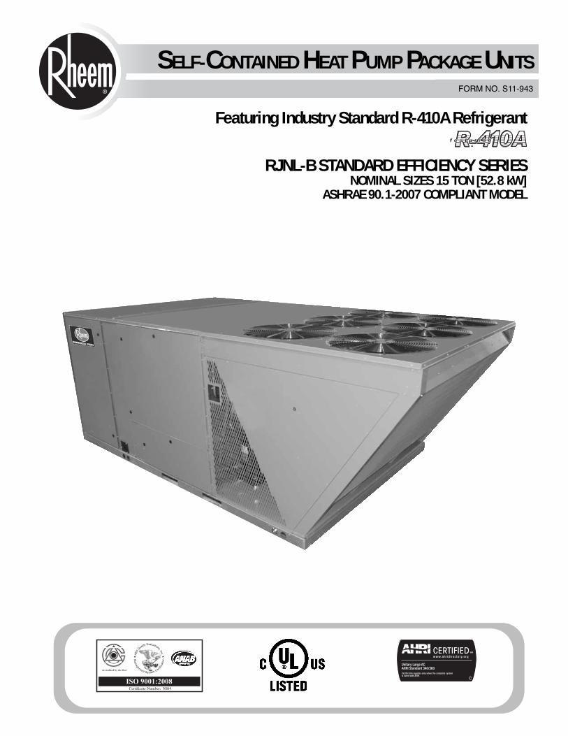
FORM NO. S11-943
RJNL-B STANDARD EFFICIENCY SERIESNOMINAL SIZES 15 TON [52.8 kW]
ASHRAE 90.1-2007 COMPLIANT MODEL
SELF-CONTAINED HEAT PUMP PACKAGE UNITS
Featuring Industry Standard R-410A Refrigerant
2
TABLE OF CONTENTS
Unit Features & Benefits ..............................................................................3-7
Selection Procedure ........................................................................................8
Model Identification Options ........................................................................9-10
General Data
RJNL-B Series ......................................................................................11-12
General Data Notes ..................................................................................13
Performance Data
RJNL-B Series ..........................................................................................14
Airflow Performance
RJNL-B Series ..........................................................................................15
Electrical Data
RJNL-B Series ..........................................................................................16
Units with Heater Kits................................................................................17-18
Dimensional Data ....................................................................................19-22
Accessories ............................................................................................23-32
Mechanical Specifications ........................................................................33-37
Typical Wiring ..........................................................................................38-39
Limited Warranty ..........................................................................................40
3
UNIT FEATURES & BENEFITS—RJNL-B SERIES
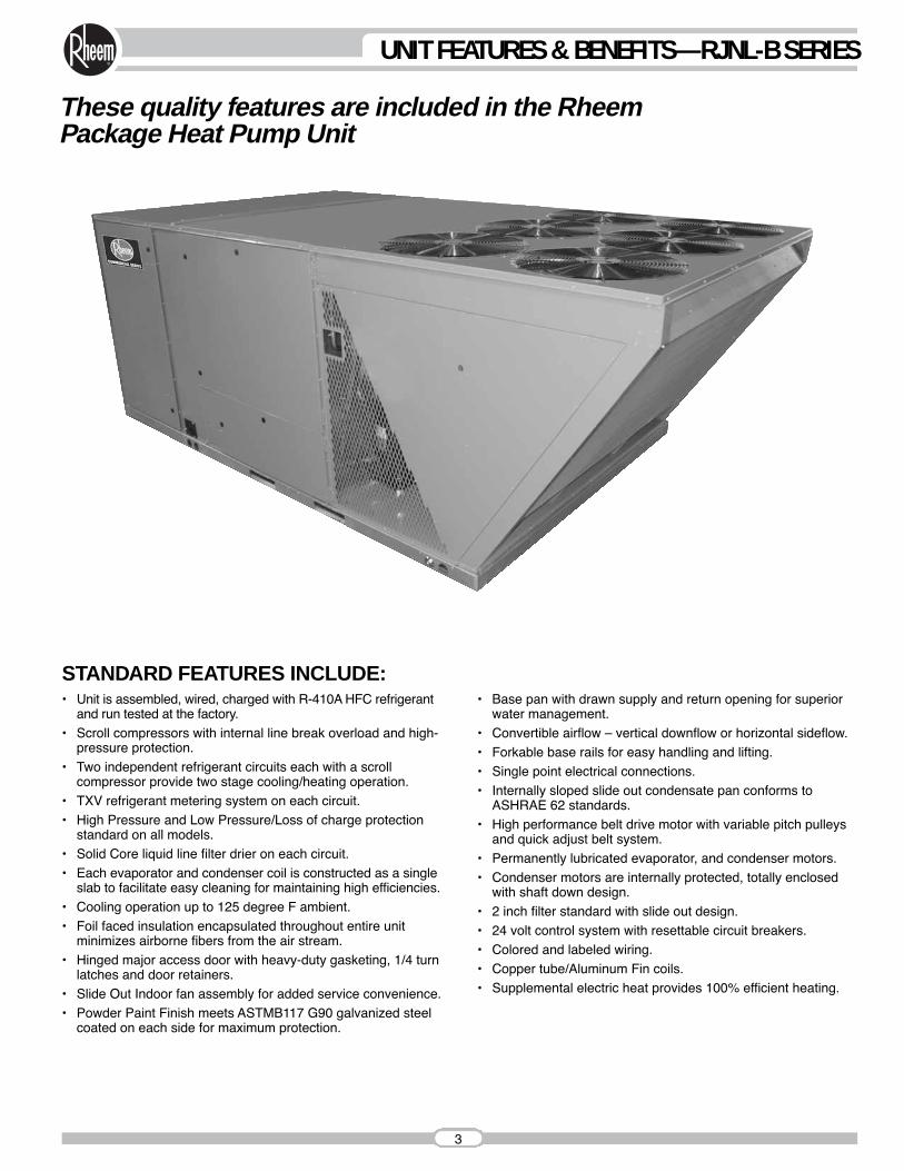
These quality features are included in the RheemPackage Heat Pump Unit
• Unit is assembled, wired, charged with R-410A HFC refrigerantand run tested at the factory.
• Scroll compressors with internal line break overload and high-pressure protection.
• Two independent refrigerant circuits each with a scrollcompressor provide two stage cooling/heating operation.
• TXV refrigerant metering system on each circuit.• High Pressure and Low Pressure/Loss of charge protection
standard on all models.• Solid Core liquid line filter drier on each circuit.• Each evaporator and condenser coil is constructed as a single
slab to facilitate easy cleaning for maintaining high efficiencies.• Cooling operation up to 125 degree F ambient.• Foil faced insulation encapsulated throughout entire unit
minimizes airborne fibers from the air stream.• Hinged major access door with heavy-duty gasketing, 1/4 turn
latches and door retainers.• Slide Out Indoor fan assembly for added service convenience.• Powder Paint Finish meets ASTMB117 G90 galvanized steel
coated on each side for maximum protection.
• Base pan with drawn supply and return opening for superiorwater management.
• Convertible airflow – vertical downflow or horizontal sideflow.• Forkable base rails for easy handling and lifting.• Single point electrical connections.• Internally sloped slide out condensate pan conforms to
ASHRAE 62 standards.• High performance belt drive motor with variable pitch pulleys
and quick adjust belt system.• Permanently lubricated evaporator, and condenser motors.• Condenser motors are internally protected, totally enclosed
with shaft down design.• 2 inch filter standard with slide out design.• 24 volt control system with resettable circuit breakers.• Colored and labeled wiring.• Copper tube/Aluminum Fin coils.• Supplemental electric heat provides 100% efficient heating.
STANDARD FEATURES INCLUDE:

4
Rheem Package equipment is designed from the ground up withthe latest features and benefits required to compete in todayʼsmarket. The clean design stands alone in the industry and is atestament to the quality, reliability, ease of installation and ser-viceability that goes into each unit. Outwardly, the large RheemCommercial Series™ label ( ) identifies the brand to the cus-tomer. The sheet-metal cabinet ( ) uses nothing less than 20-gauge material for structural components with an underlying coatof G90. To ensure the leak-proof integrity of these units, thedesign utilizes a top with a 1/8" drip lip ( ), gasket-protectedpanels and screws. ( ) The outdoor coil is slanted to protectfrom hail. Every Rheem package unit uses the toughest finish inthe industry, using electro deposition baked-on enamel tested towithstand a rigorous 1000-hour salt spray test, per ASTM B117.
Anything built to last must start with the right foundation. In thiscase, the foundation is 14-gauge, commercial-grade, full-perime-ter base rails ( ), which integrate fork slots and rigging holes tosave set-up time on the job site. The base pan is stamped, whichforms a 1-1/8" flange around the supply and return cover and haseliminated the worry of water entering the conditioned space( ). The drainpan ( ) is made of material that resists thegrowth of harmful bacteria and is sloped for the latest IAQ bene-fits. Furthermore, the drain pan slides out for easy cleaning. Theinsulation has been placed on the underside of the basepan,removing areas that would allow for potential moisture accumula-tion, which can facilitate growth of harmful bacteria. All insulationis secured with both adhesive and mechanical fasteners, and alledges are hidden.
During development, each unit was tested to U.L. 1995, AHRI340-360 and other Rheem-required reliability tests. Rheemadheres to stringent IS0 9002 quality procedures, and each unitbears the U.L. and AHRI certification labels located on the unitnameplate ( ). Contractors can rest assured that when aRheem package unit arrives at the job, it is ready to go with a factory charge and quality checks.
Access to all major compartments is from the front of the unit,including the filter and electrical compartment, blower compart-ment, heating section, and outdoor section. Each panel is perma-nently embossed with the compartment name (control/filteraccess, blower access and furnace access).
Electrical and filter compartment access is through a large,hinged-access panel with 1/4 turn latches. On the outside of thepanel is the unit nameplate, which contains the model and serialnumber, electrical data and other important unit information.
The unit charging chart is located on the inside of the electricaland filter compartment door. Electrical wiring diagrams are foundon the control box cover, which allows contractors to move themto more readable loca-tions. To the right of thecontrol box the model andserial number can befound. Having this informa-tion on the inside willassure model identificationfor the life of the product.The production line qualitytest assurance label is alsoplaced in this location ( ).The two-inch throwawayfilters ( ) are easilyremoved on a tracked sys-tem for easy replacement.
10
9
8
76
5
4
3
2
1
2
1
3
5
8
9
10
6
6
UNIT FEATURES & BENEFITS—RJNL-B SERIES
4
7
5
UNIT FEATURES & BENEFITS—RJNL-B SERIES
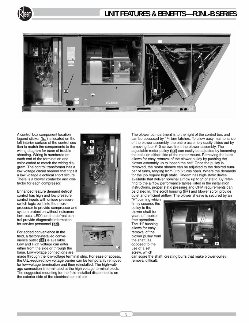
A control box component locationlegend sticker ( ) is located on theleft interior surface of the control sec-tion to match the components to thewiring diagram for ease of troubleshooting. Wiring is numbered oneach end of the termination andcolor-coded to match the wiring dia-gram. The control transformer has alow voltage circuit breaker that trips ifa low voltage electrical short occurs.There is a blower contactor and con-tactor for each compressor.
Enhanced feature demand defrostcontrol has high and low pressurecontrol inputs with unique pressureswitch logic built into the micro-processor to provide compressor andsystem protection without nuisancelock-outs. LEDʼs on the defrost con-trol provide diagnostic informationfor service personnel ( ).
For added convenience in thefield, a factory-installed conve-nience outlet ( ) is available.Low and High voltage can entereither from the side or through thebase. Low-voltage connections aremade through the low-voltage terminal strip. For ease of access,the U.L.-required low voltage barrier can be temporarily removedfor low-voltage termination and then reinstalled. The high-volt-age connection is terminated at the high voltage terminal block.The suggested mounting for the field-installed disconnect is onthe exterior side of the electrical control box.
The blower compartment is to the right of the control box andcan be accessed by 1/4 turn latches. To allow easy maintenanceof the blower assembly, the entire assembly easily slides out byremoving four #10 screws from the blower assembly. Theadjustable motor pulley ( ) can easily be adjusted by looseningthe bolts on either side of the motor mount. Removing the boltsallows for easy removal of the blower pulley by pushing theblower assembly up to loosen the belt. Once the pulley isremoved, the motor sheave can be adjusted to the desired num-ber of turns, ranging from 0 to 6 turns open. Where the demandsfor the job require high static, Rheem has high-static drivesavailable that deliver nominal airflow up to 2" of static. By refer-ring to the airflow performance tables listed in the installationinstructions, proper static pressure and CFM requirements canbe dialed in. The scroll housing ( ) and blower scroll providequiet and efficient airflow. The blower sheave is secured by an“H” bushing whichfirmly secures thepulley to theblower shaft foryears of trouble-free operation.The “H” bushingallows for easyremoval of theblower pulley fromthe shaft, asopposed to theuse of a setscrew, whichcan score the shaft, creating burrs that make blower-pulleyremoval difficult.
14
15
13
11
12
10
11
14
12
12
13
15
6
UNIT FEATURES & BENEFITS—RJNL-B SERIES
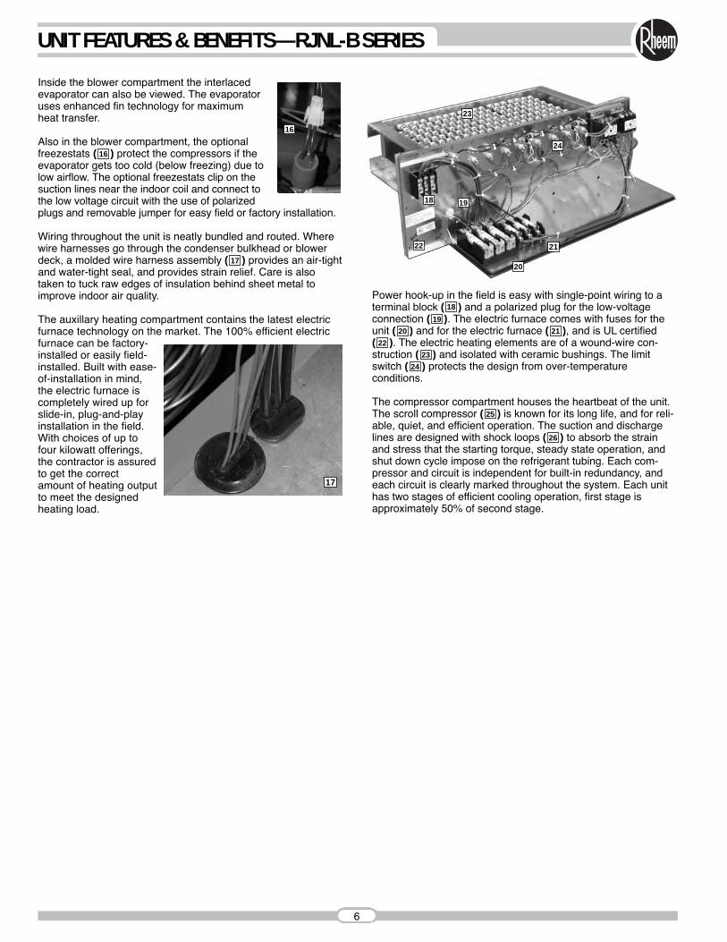
Inside the blower compartment the interlacedevaporator can also be viewed. The evaporatoruses enhanced fin technology for maximum heat transfer.
Also in the blower compartment, the optionalfreezestats ( ) protect the compressors if theevaporator gets too cold (below freezing) due tolow airflow. The optional freezestats clip on thesuction lines near the indoor coil and connect tothe low voltage circuit with the use of polarizedplugs and removable jumper for easy field or factory installation.
Wiring throughout the unit is neatly bundled and routed. Wherewire harnesses go through the condenser bulkhead or blowerdeck, a molded wire harness assembly ( ) provides an air-tightand water-tight seal, and provides strain relief. Care is alsotaken to tuck raw edges of insulation behind sheet metal toimprove indoor air quality.
The auxillary heating compartment contains the latest electricfurnace technology on the market. The 100% efficient electricfurnace can be factory-installed or easily field-installed. Built with ease-of-installation in mind,the electric furnace iscompletely wired up forslide-in, plug-and-playinstallation in the field.With choices of up tofour kilowatt offerings,the contractor is assuredto get the correctamount of heating outputto meet the designedheating load.
Power hook-up in the field is easy with single-point wiring to aterminal block ( ) and a polarized plug for the low-voltage connection ( ). The electric furnace comes with fuses for theunit ( ) and for the electric furnace ( ), and is UL certified ( ). The electric heating elements are of a wound-wire con-struction ( ) and isolated with ceramic bushings. The limitswitch ( ) protects the design from over-temperature conditions.
The compressor compartment houses the heartbeat of the unit.The scroll compressor ( ) is known for its long life, and for reli-able, quiet, and efficient operation. The suction and dischargelines are designed with shock loops ( ) to absorb the strainand stress that the starting torque, steady state operation, andshut down cycle impose on the refrigerant tubing. Each com-pressor and circuit is independent for built-in redundancy, andeach circuit is clearly marked throughout the system. Each unithas two stages of efficient cooling operation, first stage isapproximately 50% of second stage.
24
23
22
20 21
19
18
26
25
17
16
16
18
21
23
24
22
20
17
19
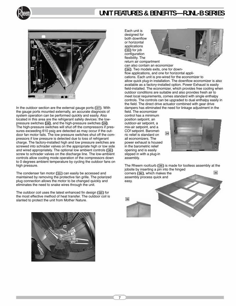
In the outdoor section are the external gauge ports ( ). Withthe gauge ports mounted externally, an accurate diagnosis ofsystem operation can be performed quickly and easily. Alsolocated in this area are the refrigerant safety devices: the low-pressure switches ( ), and the high-pressure switches ( ).The high-pressure switches will shut off the compressors if pres-sures exceeding 610 psig are detected as may occur if the out-door fan motor fails. The low pressure switches shut off the com-pressors if low pressure is detected due to loss of refrigerantcharge. The factory-installed high and low pressure switches arescrewed into schrader valves on the appropriate high or low sideand wired appropriately. The optional low ambient controls ( )screw to schrader valves on the discharge line. The low-ambientcontrols allow cooling mode operation of the compressors downto 0 degrees ambient temperature by cycling the outdoor fans onhigh pressure.
The condenser fan motor ( ) can easily be accessed and maintained by removing the protective fan grille. The polarizedplug connection allows the motor to be changed quickly andeliminates the need to snake wires through the unit.
The outdoor coil uses the latest enhanced fin design ( ) for the most effective method of heat transfer. The outdoor coil isslanted to protect the unit from Mother Nature.
Each unit isdesigned forboth downflowor horizontalapplications( ) for jobconfigurationflexibility. Thereturn air compartmentcan also contain an economizer( ). Two models exits, one for down-flow applications, and one for horizontal appli-cations. Each unit is pre-wired for the economizer toallow quick plug-in installation. The downflow economizer is alsoavailable as a factory-installed option. Power Exhaust is easilyfield-installed. The economizer, which provides free cooling whenoutdoor conditions are suitable and also provides fresh air tomeet local requirements, comes standard with single enthalpycontrols. The controls can be upgraded to dual enthalpy easily inthe field. The direct drive actuator combined with gear drivedampers has eliminated the need for linkage adjustment in thefield. The economizercontrol has a minimumposition setpoint, anoutdoor-air setpoint, amix-air setpoint, and aCO2 setpoint. Baromet-ric relief is standard onall economizers. Thepower exhaust is housedin the barometric reliefopening and is easilyslipped in with a plug-inassembly.
The Rheem roofcurb ( ) is made for toolless assembly at thejobsite by inserting a pin into the hingedcorners ( ), which makes theassembly process quick andeasy.
32
31
2928
27
36
35
34
33
30
7
UNIT FEATURES & BENEFITS—RJNL-B SERIES
35
36
30
34
33
34
30
27
26
32
32
29
28
25

8
SELECTION PROCEDURE EXAMPLE—RJNL-B SERIES
To select an RJNL-B Heat Pump unit to meet a job requirement,follow this procedure, with example, using data supplied in thisspecification sheet.
1. DETERMINE COOLING AND HEATING REQUIREMENTSAND SPECIFIC OPERATING CONDITIONS FROM PLANSAND SPECS.
Example:Voltage— 230 V — 3 Phase — 60 HzTotal Cooling Capacity— 175,000 BTUH [51.2 kW]Sensible Cooling Capacity— 140,000 BTUH [41.0 kW]Heating Capacity— 175,000 BTUH [51.2 kW]*Condenser Entering Air— 95°F [35.0 °C] DB*Evaporator Mixed Air Entering—65°F [18.3 °C] WB
78°F [25.6 °C] DB*Indoor Air Flow (vertical)— 6400 CFM [3020 L/s]*External Static Pressure— 0.60 in. WG [.15 kPa]
2. SELECT UNIT TO MEET COOLING REQUIREMENTS.
Since total cooling is within the range of a nominal 15 ton[52.7 kW] unit, enter cooling performance table at 95°F [35.0 °C] DB condenser inlet air. Interpolate between 63°F[17.2 °C] WB and 67°F [19.4 °C] WB to determine total andsensible capacity and power input for 65°F [18.3 °C] WBevaporator inlet air at 6025 CFM [2843 L/s] indoor air flow(table basis):
Total Cooling Capacity = 180,250 BTUH [52.78 kW]Sensible Cooling Capacity = 156,700 BTUH [45.88 kW]Power Input (Compressor and Cond. Fans) = 14,830 watts
Use formula in note ➀ to determine sensible capacity at 78°F[26°C] DB evaporator entering air:
Sensible Cooling Capacity = 143,887 BTUH [42.13 kW]
3. CORRECT CAPACITIES OF STEP 2 FORACTUAL AIR FLOW.
Select factors from airflow correction table at 6400 CFM [3020 L/s] and apply to data obtained in step 2 to obtain gross capacity:
Total Capacity = 180,250 x 1.02 = 183,855 BTUH [53.83 kW]Sensible Capacity = 143,887 x 1.06 = 152,520 BTUH [44.66 kW]Power Input = 14,830 x 1.01 = 14,978 Watts
These are Gross Capacities, not corrected for blower motorheat or power.
4. DETERMINE BLOWER SPEED AND WATTS TO MEETSYSTEM DESIGN.
Enter Indoor Blower performance table at 6400 CFM [3020 L/s]. Total ESP (external static pressure) per the spec of 0.60 in. WG [.15 kPa] includes the system duct and grilles.Add from the table “Component Air Resistance”, 0.1 in. WG [.02 kPa] for wet coil, 0.06 in. WG [.01 kPa] for downflow airflow, for a total selection static pressure of 0.76 (0.8) in. WG[.20 kPa], and determine:
RPM = 697WATTS = 2,402DRIVE = L (standard 3 H.P. motor)
5. CALCULATE INDOOR BLOWER BTUH HEAT EFFECTFROM MOTOR WATTS, STEP 4.
2,402 x 3.412 = 8,196 BTUH [2.40 kW]
6. CALCULATE NET COOLING CAPACITIES, EQUAL TOGROSS CAPACITY, STEP 3, MINUS INDOOR BLOWERMOTOR HEAT.
Net Total Capacity = 183,855 – 8,196 =175,659 BTUH [51.43 kW]
Net Sensible Capacity = 152,520 – 8,196 =144,324 BTUH [42.26 kW]
7. CALCULATE UNIT INPUT AND JOB EER.
Total Power Input = 14,978 (step 3) + 2,402(step 4) = 17,380 Watts
EER = Net Total BTUH [kW] (step 6) = 175,659= 10.11Power Input, Watts (above) 17,380
8. SELECT UNIT HEATING CAPACITY.
From Heater Kit Table select kW to meet heating capacityrequirement; multiply kW x 3412 to convert to BTUH
Use 50 kW Heater KitHeater Kit Model: RXJJ-CE50C Heater Kit Capacity: 170,600 BTUH [50.0 kW]
Add indoor blower heat effect (STEP 5) to Heater Kit Capacityto get total heating capacity:
170,600 + 8,196 = 178,796BTUH [52.4 kW]
9. CHOOSE MODEL RJNL-B180CL040
*NOTE: These operating conditions are typical of a commercial applica-tion in a 95°F/79°F [35°C/26°C] design area with indoor design of 76°F [24°C] DB and 50% RH and 10% ventilation air, with the unit roof mounted and centered on the zone it conditions by ducts.
[ ] Designates Metric Conversions

R J N L — B 180 C L 000 X X X
Economizer Option (See Next Page)
Factory Installed Options (See Next Page)
Electric Heat000 = No Resistance Heat020 = 20 kW Resistance Heat040 = 40 kW Resistance Heat060 = 60 kW Resistance Heat075 = 75 kW Resistance Heat
Drive PackageL = Belt DriveM = Belt Drive—High Static
Electrical DesignationC = 208-230 V, 3 PH, 60 HzD = 460 V, 3 PH, 60 HzY = 575 V, 3 PH, 60 Hz
Cooling Capacity (BTUH) [kW]180 = 180,000 [52.75]
Future Technical Variations
Design SeriesL = R410A Refrigerant
Efficiency DesignationN = ASHRAE 90.1-2007 Compliant
Product ClassificationJ = Packaged Heat Pump–
= Commercial
TradebrandR = Rheem
[ ] Designates Metric Conversions
9
MODEL IDENTIFICATION—RJNL-B SERIES
10
OPTIONS—RJNL-B SERIES
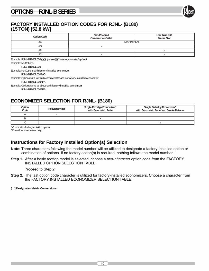
Option Code Non-PoweredConvenience Outlet
Low Ambient/Freeze Stat
AG xAP xJC x x
AA NO OPTIONS
FACTORY INSTALLED OPTION CODES FOR RJNL- (B180)(15 TON) [52.8 kW]
ECONOMIZER SELECTION FOR RJNL- (B180)
Example: RJNL-B180CL000XXX (where XX is factory installed option)Example: No Options
RJNL-B180CL000Example: No Options with factory installed economizer
RJNL-B180CL000AAB Example: Options with low ambient/freezestat and no factory installed economizer
RJNL-B180CL000APAExample: Options same as above with factory installed economizer
RJNL-B180CL000APB
OptionCode No Economizer Single Enthalpy Economizer*
With Barometric ReliefA xB x
Single Enthalpy Economizer*With Barometric Relief and Smoke Detector
C x
“x” indicates factory installed option.*Downflow economizer only.
Instructions for Factory Installed Option(s) SelectionNote: Three characters following the model number will be utilized to designate a factory-installed option or
combination of options. If no factory option(s) is required, nothing follows the model number.
Step 1. After a basic rooftop model is selected, choose a two-character option code from the FACTORYINSTALLED OPTION SELECTION TABLE.
Proceed to Step 2.
Step 2. The last option code character is utilized for factory-installed economizers. Choose a character fromthe FACTORY INSTALLED ECONOMIZER SELECTION TABLE.
[ ] Designates Metric Conversions
11
GENERAL DATA—RJNL-B SERIES
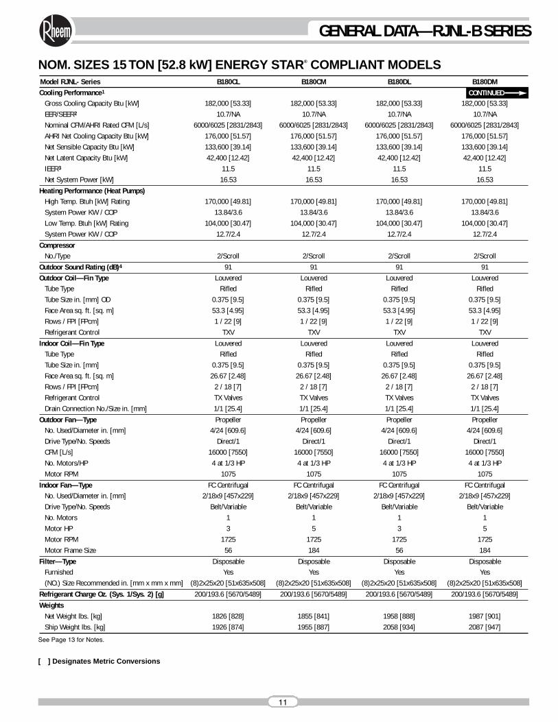
Model RJNL- Series B180CL B180CM B180DL B180DMCooling Performance1
Gross Cooling Capacity Btu [kW] 182,000 [53.33] 182,000 [53.33] 182,000 [53.33] 182,000 [53.33]EER/SEER2 10.7/NA 10.7/NA 10.7/NA 10.7/NANominal CFM/AHRI Rated CFM [L/s] 6000/6025 [2831/2843] 6000/6025 [2831/2843] 6000/6025 [2831/2843] 6000/6025 [2831/2843]AHRI Net Cooling Capacity Btu [kW] 176,000 [51.57] 176,000 [51.57] 176,000 [51.57] 176,000 [51.57]Net Sensible Capacity Btu [kW] 133,600 [39.14] 133,600 [39.14] 133,600 [39.14] 133,600 [39.14]Net Latent Capacity Btu [kW] 42,400 [12.42] 42,400 [12.42] 42,400 [12.42] 42,400 [12.42]IEER3 11.5 11.5 11.5 11.5Net System Power [kW] 16.53 16.53 16.53 16.53
Heating Performance (Heat Pumps)High Temp. Btuh [kW] Rating 170,000 [49.81] 170,000 [49.81] 170,000 [49.81] 170,000 [49.81]System Power KW / COP 13.84/3.6 13.84/3.6 13.84/3.6 13.84/3.6Low Temp. Btuh [kW] Rating 104,000 [30.47] 104,000 [30.47] 104,000 [30.47] 104,000 [30.47]System Power KW / COP 12.7/2.4 12.7/2.4 12.7/2.4 12.7/2.4
CompressorNo./Type 2/Scroll 2/Scroll 2/Scroll 2/Scroll
Outdoor Sound Rating (dB)4 91 91 91 91Outdoor Coil—Fin Type Louvered Louvered Louvered Louvered
Tube Type Rifled Rifled Rifled RifledTube Size in. [mm] OD 0.375 [9.5] 0.375 [9.5] 0.375 [9.5] 0.375 [9.5]Face Area sq. ft. [sq. m] 53.3 [4.95] 53.3 [4.95] 53.3 [4.95] 53.3 [4.95]Rows / FPI [FPcm] 1 / 22 [9] 1 / 22 [9] 1 / 22 [9] 1 / 22 [9]Refrigerant Control TXV TXV TXV TXV
Indoor Coil—Fin Type Louvered Louvered Louvered LouveredTube Type Rifled Rifled Rifled RifledTube Size in. [mm] 0.375 [9.5] 0.375 [9.5] 0.375 [9.5] 0.375 [9.5]Face Area sq. ft. [sq. m] 26.67 [2.48] 26.67 [2.48] 26.67 [2.48] 26.67 [2.48]Rows / FPI [FPcm] 2 / 18 [7] 2 / 18 [7] 2 / 18 [7] 2 / 18 [7]Refrigerant Control TX Valves TX Valves TX Valves TX ValvesDrain Connection No./Size in. [mm] 1/1 [25.4] 1/1 [25.4] 1/1 [25.4] 1/1 [25.4]
Outdoor Fan—Type Propeller Propeller Propeller PropellerNo. Used/Diameter in. [mm] 4/24 [609.6] 4/24 [609.6] 4/24 [609.6] 4/24 [609.6]Drive Type/No. Speeds Direct/1 Direct/1 Direct/1 Direct/1CFM [L/s] 16000 [7550] 16000 [7550] 16000 [7550] 16000 [7550]No. Motors/HP 4 at 1/3 HP 4 at 1/3 HP 4 at 1/3 HP 4 at 1/3 HPMotor RPM 1075 1075 1075 1075
Indoor Fan—Type FC Centrifugal FC Centrifugal FC Centrifugal FC CentrifugalNo. Used/Diameter in. [mm] 2/18x9 [457x229] 2/18x9 [457x229] 2/18x9 [457x229] 2/18x9 [457x229]Drive Type/No. Speeds Belt/Variable Belt/Variable Belt/Variable Belt/VariableNo. Motors 1 1 1 1Motor HP 3 5 3 5Motor RPM 1725 1725 1725 1725Motor Frame Size 56 184 56 184
Filter—Type Disposable Disposable Disposable DisposableFurnished Yes Yes Yes Yes(NO.) Size Recommended in. [mm x mm x mm] (8)2x25x20 [51x635x508] (8)2x25x20 [51x635x508] (8)2x25x20 [51x635x508] (8)2x25x20 [51x635x508]
Refrigerant Charge Oz. (Sys. 1/Sys. 2) [g] 200/193.6 [5670/5489] 200/193.6 [5670/5489] 200/193.6 [5670/5489] 200/193.6 [5670/5489]Weights
Net Weight lbs. [kg] 1826 [828] 1855 [841] 1958 [888] 1987 [901]Ship Weight lbs. [kg] 1926 [874] 1955 [887] 2058 [934] 2087 [947]
CONTINUED
NOM. SIZES 15 TON [52.8 kW] ENERGY STAR® COMPLIANT MODELS
See Page 13 for Notes.
[ ] Designates Metric Conversions
12
GENERAL DATA—RJNL-B SERIES
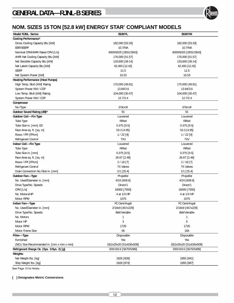
Model RJNL- Series B180YL B180YMCooling Performance1
Gross Cooling Capacity Btu [kW] 182,000 [53.33] 182,000 [53.33]EER/SEER2 10.7/NA 10.7/NANominal CFM/AHRI Rated CFM [L/s] 6000/6025 [2831/2843] 6000/6025 [2831/2843]AHRI Net Cooling Capacity Btu [kW] 176,000 [51.57] 176,000 [51.57]Net Sensible Capacity Btu [kW] 133,600 [39.14] 133,600 [39.14]Net Latent Capacity Btu [kW] 42,400 [12.42] 42,400 [12.42]IEER3 11.5 11.5Net System Power [kW] 16.53 16.53
Heating Performance (Heat Pumps)High Temp. Btuh [kW] Rating 170,000 [49.81] 170,000 [49.81]System Power KW / COP 13.84/3.6 13.84/3.6Low Temp. Btuh [kW] Rating 104,000 [30.47] 104,000 [30.47]System Power KW / COP 12.7/2.4 12.7/2.4
CompressorNo./Type 2/Scroll 2/Scroll
Outdoor Sound Rating (dB)4 91 91Outdoor Coil—Fin Type Louvered Louvered
Tube Type Rifled RifledTube Size in. [mm] OD 0.375 [9.5] 0.375 [9.5]Face Area sq. ft. [sq. m] 53.3 [4.95] 53.3 [4.95]Rows / FPI [FPcm] 1 / 22 [9] 1 / 22 [9]Refrigerant Control TXV TXV
Indoor Coil—Fin Type Louvered LouveredTube Type Rifled RifledTube Size in. [mm] 0.375 [9.5] 0.375 [9.5]Face Area sq. ft. [sq. m] 26.67 [2.48] 26.67 [2.48]Rows / FPI [FPcm] 2 / 18 [7] 2 / 18 [7]Refrigerant Control TX Valves TX ValvesDrain Connection No./Size in. [mm] 1/1 [25.4] 1/1 [25.4]
Outdoor Fan—Type Propeller PropellerNo. Used/Diameter in. [mm] 4/24 [609.6] 4/24 [609.6]Drive Type/No. Speeds Direct/1 Direct/1CFM [L/s] 16000 [7550] 16000 [7550]No. Motors/HP 4 at 1/3 HP 4 at 1/3 HPMotor RPM 1075 1075
Indoor Fan—Type FC Centrifugal FC CentrifugalNo. Used/Diameter in. [mm] 2/18x9 [457x229] 2/18x9 [457x229]Drive Type/No. Speeds Belt/Variable Belt/VariableNo. Motors 1 1Motor HP 3 5Motor RPM 1725 1725Motor Frame Size 56 184
Filter—Type Disposable DisposableFurnished Yes Yes(NO.) Size Recommended in. [mm x mm x mm] (8)2x25x20 [51x635x508] (8)2x25x20 [51x635x508]
Refrigerant Charge Oz. (Sys. 1/Sys. 2) [g] 200/193.6 [5670/5489] 200/193.6 [5670/5489]Weights
Net Weight lbs. [kg] 1826 [828] 1855 [841]Ship Weight lbs. [kg] 1926 [874] 1955 [887]
NOM. SIZES 15 TON [52.8 kW] ENERGY STAR® COMPLIANT MODELS
See Page 13 for Notes.
[ ] Designates Metric Conversions
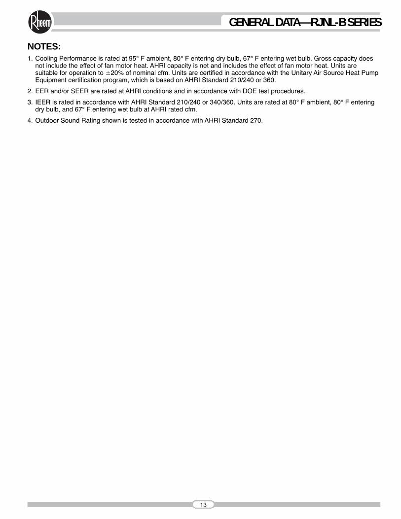
NOTES:1. Cooling Performance is rated at 95° F ambient, 80° F entering dry bulb, 67° F entering wet bulb. Gross capacity does
not include the effect of fan motor heat. AHRI capacity is net and includes the effect of fan motor heat. Units aresuitable for operation to �20% of nominal cfm. Units are certified in accordance with the Unitary Air Source Heat PumpEquipment certification program, which is based on AHRI Standard 210/240 or 360.
2. EER and/or SEER are rated at AHRI conditions and in accordance with DOE test procedures.
3. IEER is rated in accordance with AHRI Standard 210/240 or 340/360. Units are rated at 80° F ambient, 80° F enteringdry bulb, and 67° F entering wet bulb at AHRI rated cfm.
4. Outdoor Sound Rating shown is tested in accordance with AHRI Standard 270.
13
GENERAL DATA—RJNL-B SERIES
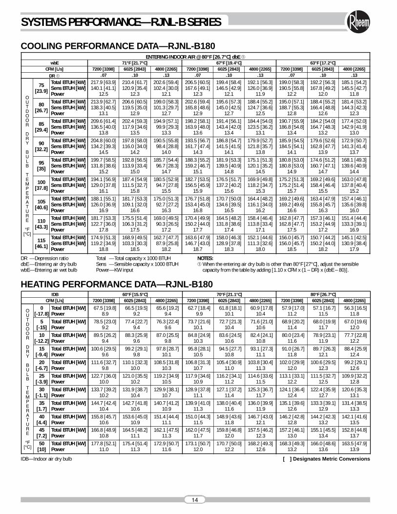
COOLING PERFORMANCE DATA—RJNL-B180ENTERING INDOOR AIR @ 80°F [26.7°C] dbE ➀
wbE 71°F [21.7°C] 67°F [19.4°C] 63°F [17.2°C]CFM [L/s] 7200 [3398] 6025 [2843] 4800 [2265] 7200 [3398] 6025 [2843] 4800 [2265] 7200 [3398] 6025 [2843] 4800 [2265]
DR ➀ .07 .10 .13 .07 .10 .13 .07 .10 .13
OUTDOOR
DRY
BULB
TEMPERATURE
°F[°C]
75[23.9]
Total BTUH [kW]Sens BTUH [kW]Power
217.9 [63.9]140.1 [41.1]
12.5
210.4 [61.7]120.9 [35.4]
12.3
202.6 [59.4]102.4 [30.0]
12.1
206.5 [60.5]167.6 [49.1]
12.3
199.4 [58.4]146.5 [42.9]
12.1
192.1 [56.3]126.0 [36.9]
11.9
199.0 [58.3]190.5 [55.8]
12.2
192.2 [56.3]167.8 [49.2]
12.0
185.1 [54.2]145.5 [42.7]
11.8
80[26.7]
Total BTUH [kW]Sens BTUH [kW]Power
213.9 [62.7]138.3 [40.5]
13.1
206.6 [60.5]119.5 [35.0]
12.9
199.0 [58.3]101.3 [29.7]
12.7
202.6 [59.4]165.8 [48.6]
12.9
195.6 [57.3]145.0 [42.5]
12.7
188.4 [55.2]124.7 [36.6]
12.5
195.0 [57.1]188.7 [55.3]
12.8
188.4 [55.2]166.4 [48.8]
12.6
181.4 [53.2]144.3 [42.3]
12.3
85[29.4]
Total BTUH [kW]Sens BTUH [kW]Power
209.6 [61.4]136.5 [40.0]
13.8
202.4 [59.3]117.9 [34.6]
13.5
194.9 [57.1]99.9 [29.3]
13.3
198.2 [58.1]163.9 [48.0]
13.6
191.4 [56.1]143.4 [42.0]
13.4
184.4 [54.0]123.5 [36.2]
13.1
190.7 [55.9]186.8 [54.8]
13.4
184.2 [54.0]164.7 [48.3]
13.2
177.4 [52.0]142.9 [41.9]
13.0
90[32.2]
Total BTUH [kW]Sens BTUH [kW]Power
204.8 [60.0]134.2 [39.3]
14.5
197.8 [58.0]116.0 [34.0]
14.2
190.5 [55.8]98.4 [28.8]
14.0
193.5 [56.7]161.7 [47.4]
14.3
186.8 [54.7]141.5 [41.5]
14.1
179.9 [52.7]121.8 [35.7]
13.8
185.9 [54.5]184.5 [54.1]
14.1
179.6 [52.6]162.8 [47.7]
13.9
172.9 [50.7]141.3 [41.4]
13.7
95[35]
Total BTUH [kW]Sens BTUH [kW]Power
199.7 [58.5]131.8 [38.6]
15.2
192.8 [56.5]113.9 [33.4]
15.0
185.7 [54.4]96.7 [28.3]
14.7
188.3 [55.2]159.2 [46.7]
15.1
181.9 [53.3]139.5 [40.9]
14.8
175.1 [51.3]120.1 [35.2]
14.5
180.8 [53.0]180.8 [53.0]
14.9
174.6 [51.2]160.7 [47.1]
14.7
168.1 [49.3]139.6 [40.9]
14.4
100[37.8]
Total BTUH [kW]Sens BTUH [kW]Power
194.1 [56.9]129.0 [37.8]
16.1
187.4 [54.9]111.5 [32.7]
15.8
180.5 [52.9]94.7 [27.8]
15.5
182.7 [53.5]156.5 [45.9]
15.9
176.5 [51.7]137.2 [40.2]
15.6
169.9 [49.8]118.2 [34.7]
15.3
175.2 [51.3]175.2 [51.4]
15.7
169.2 [49.6]158.4 [46.4]
15.5
163.0 [47.8]137.8 [40.4]
15.2
105[40.6]
Total BTUH [kW]Sens BTUH [kW]Power
188.1 [55.1]126.0 [36.9]
16.9
181.7 [53.3]109.1 [32.0]
16.6
175.0 [51.3]92.7 [27.2]
16.3
176.7 [51.8]153.4 [45.0]
16.8
170.7 [50.0]134.6 [39.5]
16.5
164.4 [48.2]116.1 [34.0]
16.2
169.2 [49.6]169.2 [49.6]
16.6
163.4 [47.9]155.8 [45.7]
16.3
157.4 [46.1]135.6 [39.8]
16.0
110[43.3]
Total BTUH [kW]Sens BTUH [kW]Power
181.7 [53.3]122.7 [36.0]
17.8
175.5 [51.4]106.3 [31.2]
17.5
169.0 [49.5]90.3 [26.5]
17.2
170.4 [49.9]150.2 [44.0]
17.7
164.5 [48.2]131.8 [38.6]
17.4
158.4 [46.4]113.8 [33.4]
17.1
162.8 [47.7]162.8 [47.7]
17.5
157.3 [46.1]153.2 [44.9]
17.2
151.4 [44.4]133.3 [39.1]
16.9
115[46.1]
Total BTUH [kW]Sens BTUH [kW]Power
174.9 [51.3]119.2 [34.9]
18.8
168.9 [49.5]103.3 [30.3]
18.5
162.7 [47.7]87.9 [25.8]
18.2
163.6 [47.9]146.7 [43.0]
18.7
158.0 [46.3]128.9 [37.8]
18.3
152.1 [44.6]111.3 [32.6]
18.0
156.0 [45.7]156.0 [45.7]
18.5
150.7 [44.2]150.2 [44.0]
18.2
145.1 [42.5]130.9 [38.4]
17.9
HEATING PERFORMANCE DATA—RJNL-B180
DR —Depression ratiodbE —Entering air dry bulbwbE—Entering air wet bulb
Total —Total capacity x 1000 BTUHSens —Sensible capacity x 1000 BTUHPower—KW input
NOTES:➀ When the entering air dry bulb is other than 80°F [27°C], adjust the sensible
capacity from the table by adding [1.10 x CFM x (1 – DR) x (dbE – 80)].
IDB 60°F [15.5°C] 70°F [21.1°C] 80°F [26.7°C]CFM [L/s] 7200 [3398] 6025 [2843] 4800 [2265] 7200 [3398] 6025 [2843] 4800 [2265] 7200 [3398] 6025 [2843] 4800 [2265]
OUTDOOR
DRY
BULB
TEMPERATURE
°F[°C]
0[-17.8]
Total BTUH [kW]Power
67.5 [19.8]8.9
66.5 [19.5]9.2
65.6 [19.2]9.4
62.7 [18.4]9.9
61.8 [18.1]10.1
60.9 [17.8]10.4
57.9 [17.0]11.2
57.1 [16.7]11.5
56.3 [16.5]11.8
5[-15]
Total BTUH [kW]Power
78.5 [23.0]9.2
77.4 [22.7]9.4
76.3 [22.4]9.6
73.7 [21.6]10.1
72.7 [21.3]10.4
71.6 [21.0]10.6
68.9 [20.2]11.4
68.0 [19.9]11.7
67.0 [19.6]12.0
10[-12.2]
Total BTUH [kW]Power
89.5 [26.2]9.4
88.3 [25.9]9.6
87.0 [25.5]9.8
84.8 [24.9]10.3
83.6 [24.5]10.6
82.4 [24.1]10.8
80.0 [23.4]11.6
78.9 [23.1]11.9
77.7 [22.8]12.2
15[-9.4]
Total BTUH [kW]Power
100.6 [29.5]9.6
99.2 [29.1]9.8
97.8 [28.7]10.1
95.8 [28.1]10.5
94.5 [27.7]10.8
93.1 [27.3]11.1
91.0 [26.7]11.8
89.7 [26.3]12.1
88.4 [25.9]12.4
20[-6.7]
Total BTUH [kW]Power
111.6 [32.7]9.8
110.1 [32.3]10.0
108.5 [31.8]10.3
106.8 [31.3]10.7
105.4 [30.9]11.0
103.8 [30.4]11.3
102.0 [29.9]12.0
100.6 [29.5]12.3
99.2 [29.1]12.6
25[-3.9]
Total BTUH [kW]Power
122.7 [36.0]10.0
121.0 [35.5]10.2
119.2 [34.9]10.5
117.9 [34.6]10.9
116.2 [34.1]11.2
114.6 [33.6]11.5
113.1 [33.1]12.2
111.5 [32.7]12.5
109.9 [32.2]12.8
30[-1.1]
Total BTUH [kW]Power
133.7 [39.2]10.2
131.9 [38.7]10.4
129.9 [38.1]10.7
128.9 [37.8]11.1
127.1 [37.2]11.4
125.3 [36.7]11.7
124.1 [36.4]12.4
122.4 [35.9]12.7
120.6 [35.3]13.1
35[1.7]
Total BTUH [kW]Power
144.7 [42.4]10.4
142.7 [41.8]10.6
140.7 [41.2]10.9
139.9 [41.0]11.3
138.0 [40.4]11.6
136.0 [39.9]11.9
135.1 [39.6]12.6
133.3 [39.1]12.9
131.4 [38.5]13.3
40[4.4]
Total BTUH [kW]Power
155.8 [45.7]10.6
153.6 [45.0]10.9
151.4 [44.4]11.1
151.0 [44.3]11.5
148.9 [43.6]11.8
146.7 [43.0]12.1
146.2 [42.8]12.8
144.2 [42.3]13.2
142.1 [41.6]13.5
45[7.2]
Total BTUH [kW]Power
166.8 [48.9]10.8
164.5 [48.2]11.1
162.1 [47.5]11.3
162.0 [47.5]11.7
159.8 [46.8]12.0
157.5 [46.2]12.3
157.2 [46.1]13.0
155.1 [45.5]13.4
152.8 [44.8]13.7
50[10]
Total BTUH [kW]Power
177.8 [52.1]11.0
175.4 [51.4]11.3
172.9 [50.7]11.6
173.1 [50.7]12.0
170.7 [50.0]12.2
168.2 [49.3]12.6
168.3 [49.3]13.2
166.0 [48.6]13.6
163.5 [47.9]13.9
14
SYSTEMS PERFORMANCE—RJNL-B SERIES
IDB—Indoor air dry bulb [ ] Designates Metric Conversions
AIR
FL
OW
PE
RF
OR
MA
NC
E—
15 T
ON
[52.
8 kW
]–S
IDE
FL
OW
850
3253
868
6200
[292
6]—
——
—57
016
5059
517
8361
919
1364
320
4266
621
6968
822
9371
024
1573
125
3575
226
5377
327
2879
228
5481
229
8483
131
1664
00 [3
020]
——
——
579
1750
604
1885
628
2017
652
2148
674
2276
697
2402
718
2526
739
2648
760
2767
780
2852
800
2983
819
3118
3392
838
3255
6600
[311
4]—
——
—58
918
5461
419
9163
721
2566
122
5768
323
8670
525
1472
726
4074
827
6376
828
8478
829
8480
831
1982
7
903
3258
7200
[339
8]
845
570
3400
1897
6800
[320
9]
595
—
2042
—
619
574
2185
1822
643
599
2327
1961
666
623
2466
2099
689
647
2602
2235
711
670
2369
RPM
WRP
MW
RPM
WRP
MW
RPM
WRP
MW
RPM
WRP
MW
RPM
WRP
MW
RPM
WRP
MW
RPM
WRP
MW
RPM
W48
00 [2
265]
——
——
——
——
——
583
1393
608
1508
632
1621
656
1732
679
1841
701
1947
723
2052
744
2154
764
2254
785
2326
5000
[235
9]—
——
——
——
——
—59
114
7661
615
9364
017
0766
318
2068
619
3070
820
3872
921
4575
022
4877
123
5079
124
2052
00 [2
454]
——
——
——
——
575
1442
600
1562
624
1681
648
1797
671
1911
693
2023
715
2133
736
2241
757
2346
777
2410
797
2520
5400
[254
8]—
——
——
——
—58
315
3060
816
5263
217
7265
518
9067
820
0570
121
1972
222
3174
323
4076
424
4778
425
1280
426
2656
00 [2
643]
——
——
——
——
592
1621
616
1745
640
1866
663
1986
686
2103
708
2218
729
2331
750
2442
770
2551
791
2620
810
2739
5800
[273
7]—
——
——
—57
615
8860
117
1562
518
4064
919
6467
220
8569
422
0471
623
2173
724
3675
725
4877
826
1479
827
3581
728
5860
00 [2
831]
——
——
——
585
1683
610
1813
634
1940
657
2065
680
2187
702
2308
724
2426
744
2543
765
2657
785
2731
805
2856
824
2984
7000
[330
3]—
—58
419
3060
920
7263
322
1165
623
4967
924
8470
126
1772
327
4874
428
7776
430
0378
531
2480
432
6582
334
1084
235
5986
037
1069
225
0071
426
2973
527
5675
628
8277
629
8479
631
2181
532
6283
434
0585
335
52
2737
3682
886
3535
856
3396
875
3541
892
3688
863
3546
881
3695
899
3847
732
2870
753
RPM
WRP
MW
RPM
W80
524
3082
525
3784
426
4781
125
2883
026
4085
027
5581
726
3383
627
4985
528
6982
327
4484
228
6586
129
8983
028
6184
929
8786
731
1683
629
8585
531
1687
332
4984
331
1686
132
5187
933
89
878
3865
895
4024
912
4185
871
3702
888
3856
905
4013
Mod
el R
JNL-
B180
V
olta
ge 2
08/2
30, 4
60, 5
75 —
3 P
hase
3000
920
773
3127
793
3270
812
3416
831
3566
849
3719
868
3875
885
4035
902
4198
919
4364
Air
Flow
CFM
[L/s
]
3832
909
3839
926
3994
916
4003
——
RPM
WRP
MW
863
2761
881
2878
868
2873
887
2995
874
2992
892
3118
879
3117
897
3248
885
3248
903
3384
891
3386
909
3527
897
3531
914
3676
929
4350
——
922
4173
——
——
——
0.1
[.02
]0.
2 [.
05]
0.3
[.07
]0.
4 [.
10]
0.5
[.12
]0.
6 [.
15]
0.7
[.17
]0.
8 [.
20]
0.9
[.22
]1.
0 [.
25]
1.1
[.27
]1.
2 [.
30]
1.3
[.32
]1.
4 [.
35]
1.5
[.37
]1.
6 [.
40]
1.7
[.42
]1.
8 [.
45]
1.9
[.47
]2.
0 [.
50]
Exte
rnal
Sta
tic P
ress
ure—
Inch
es o
f Wat
er [k
Pa]
Driv
e Pa
ckag
eL
MM
otor
H.P.
[W]
3.0
[223
7.1]
5.0
[372
8.5]
Blow
er S
heav
eBK
105H
BK10
5HM
otor
She
ave
1VL-
441V
P-56
Turn
s Op
en1
23
45
61
23
45
6RP
M73
370
166
964
060
557
292
790
387
384
080
877
5
NOTE
: L-D
rive
left
of b
old
line,
M-D
rive
right
of b
old
line.
AIR
FL
OW
CO
RR
EC
TIO
N F
AC
TOR
S—
15 T
ON
[52.
8 kW
]
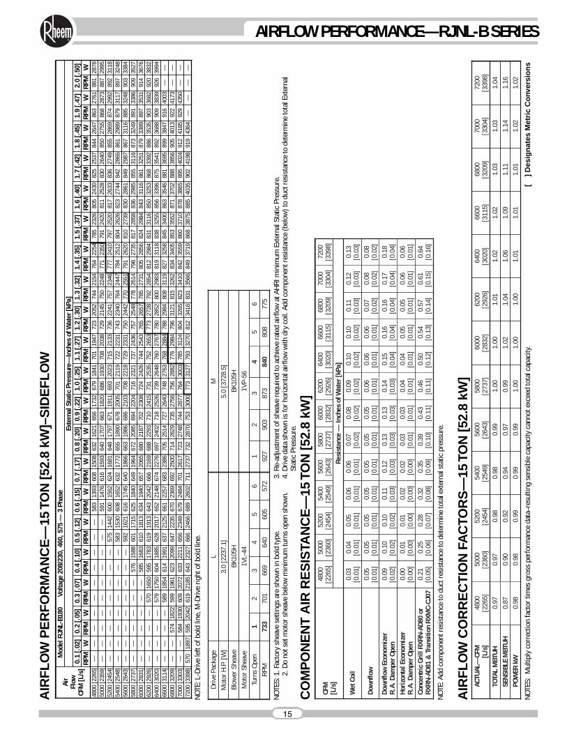
NOTE
S: M
ultip
ly c
orre
ctio
n fa
ctor
tim
es g
ross
per
form
ance
dat
a–re
sulti
ng s
ensi
ble
capa
city
can
not e
xcee
d to
tal c
apac
ity.
[ ]
Des
ign
ates
Met
ric
Co
nver
sio
ns
0.97
0.98
TOTA
L M
BTUH
0.99
0.97
0.94
5400
[254
9]1.
001.
01
1.00
0.98
1.04
6200
[292
6]
POW
ER k
W1.
000.
980.
99
5800
[273
7]
0.90
SENS
IBLE
MBT
UH0.
87
5000
[236
0]AC
TUAL
—CF
M[L
/s]
4800
[226
5]1.
02
1.01
1.09
6600
[311
5]1.
03
1.02
1.14
7000
[330
4]1.
04
1.02
1.16
7200
[339
8]1.
03
1.01
1.11
6800
[320
9]1.
02
1.01
1.06
6400
[302
0]1.
00
1.00
1.02
6000
[283
2]0.
99
0.99
0.97
5600
[264
3]0.
98
0.99
0.92
5200
[245
4]
CO
MP
ON
EN
T A
IR R
ES
ISTA
NC
E—
15 T
ON
[52.
8 kW
]CF
M[L
/s]
4800
[226
5]
Wet
Coi
l0.
03[0
.01]
Dow
nflo
w0.
05[0
.01]
0.05
[0.0
1]
0.04
[0.0
1]
5000
[236
0]
0.05
[0.0
1]
0.05
[0.0
1]
5200
[245
4]
0.05
[0.0
1]
0.06
[0.0
1]
5400
[254
9]
0.05
[0.0
1]
0.06
[0.0
1]
5600
[264
3]
0.05
[0.0
1]
0.07
[0.0
2]
5800
[273
7]
0.05
[0.0
1]
0.08
[0.0
2]
6000
[283
2]
Dow
nflo
w E
cono
miz
er
R.A.
Dam
per O
pen
0.09
[0.0
2]
Conc
entri
c Gr
ill R
XRN-
AD80
or
RXRN
-AD8
1 &
Tra
nsiti
on R
XMC-
CJ07
0.21
[0.0
5]0.
43[0
.11]
0.13
[0.0
3]
0.25
[0.0
6]
0.10
[0.0
2]
0.28
[0.0
7]
0.10
[0.0
2]
0.32
[0.0
8]
0.11
[0.0
3]
0.35
[0.0
9]
0.12
[0.0
3]
0.39
[0.1
0]
0.13
[0.0
3]Ho
rizon
tal E
cono
miz
erR.
A. D
ampe
r Ope
n0.
00[0
.00]
0.03
[0.0
1]0.
01[0
.00]
0.01
[0.0
0]0.
02[0
.00]
0.02
[0.0
0]0.
03[0
.01]
0.46
[0.1
1]
0.04
[0.0
1]
0.14
[0.0
3]
0.06
[0.0
1]
0.09
[0.0
2]
6200
[292
6]
0.50
[0.1
2]
0.04
[0.0
1]
0.15
[0.0
4]
0.06
[0.0
1]
0.10
[0.0
2]
6400
[302
0]
0.54
[0.1
3]
0.05
[0.0
1]
0.16
[0.0
4]
0.06
[0.0
1]
0.10
[0.0
2]
6600
[311
5]
0.57
[0.1
4]
0.05
[0.0
1]
0.16
[0.0
4]
0.07
[0.0
2]
0.11
[0.0
3]
6800
[320
9]
0.61
[0.1
5]
0.06
[0.0
1]
0.17
[0.0
4]
0.08
[0.0
2]
0.12
[0.0
3]
7000
[330
4]
0.64
[0.1
6]
0.06
[0.0
1]
0.18
[0.0
4]
0.08
[0.0
2]
0.13
[0.0
3]
7200
[339
8]Re
sist
ance
— In
ches
of W
ater
[kPa
]
NOTE
: Add
com
pone
nt re
sist
ance
to d
uct r
esis
tanc
e to
det
erm
ine
tota
l ext
erna
l sta
tic p
ress
ure.
NOTE
S: 1
. Fac
tory
she
ave
setti
ngs
are
show
n in
bol
d ty
pe.
2. D
o no
t set
mot
or s
heav
e be
low
min
imum
turn
s op
en s
how
n.3.
Re-
adju
stm
ent o
f she
ave
requ
ired
to a
chie
ve ra
ted
airf
low
at A
HRI m
inim
um E
xter
nal S
tatic
Pre
ssur
e.4.
Driv
e da
ta s
how
n is
for h
orizo
ntal
airf
low
with
dry
coi
l. Ad
d co
mpo
nent
resi
stan
ce (b
elow
) to
duct
resi
stan
ce to
det
erm
ine
tota
l Ext
erna
l St
atic
Pre
ssur
e.
15
AIRFLOW PERFORMANCE—RJNL-B SERIES
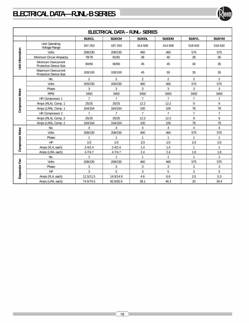
ELECTRICAL DATA – RJNL- SERIESB180CL B180CM B180DL B180DM B180YL B180YM
Unit
Info
rmat
ion
Unit OperatingVoltage Range 187-253 187-253 414-506 414-506 518-632 518-632
Volts 208/230 208/230 460 460 575 575Minimum Circuit Ampacity 78/78 81/81 38 40 28 30
Minimum OvercurrentProtection Device Size 90/90 90/90 45 45 30 35
Maximum OvercurrentProtection Device Size 100/100 100/100 45 50 35 35
Com
pres
sor M
otor
No. 2 2 2 2 2 2Volts 200/230 200/230 460 460 575 575Phase 3 3 3 3 3 3RPM 3450 3450 3450 3450 3450 3450
HP, Compressor 1 7 7 7 7 7 7Amps (RLA), Comp. 1 25/25 25/25 12.2 12.2 9 9Amps (LRA), Comp. 1 164/164 164/164 100 100 78 78
HP, Compressor 2 7 7 7 7 7 7Amps (RLA), Comp. 2 25/25 25/25 12.2 12.2 9 9Amps (LRA), Comp. 2 164/164 164/164 100 100 78 78
Com
pres
sor M
otor No. 4 4 4 4 4 4
Volts 208/230 208/230 460 460 575 575Phase 1 1 1 1 1 1
HP 1/3 1/3 1/3 1/3 1/3 1/3Amps (FLA, each) 2.4/2.4 2.4/2.4 1.4 1.4 1 1Amps (LRA, each) 4.7/4.7 4.7/4.7 2.4 2.4 1.8 1.8
Evap
orat
or F
an
No. 1 1 1 1 1 1Volts 208/230 208/230 460 460 575 575Phase 3 3 3 3 3 3
HP 3 5 3 5 3 5Amps (FLA, each) 11.5/11.5 14.9/14.9 4.6 6.6 3.5 5.3Amps (LRA, each) 74.5/74.5 82.6/82.6 38.1 46.3 20 39.4
16
ELECTRICAL DATA—RJNL-B SERIES
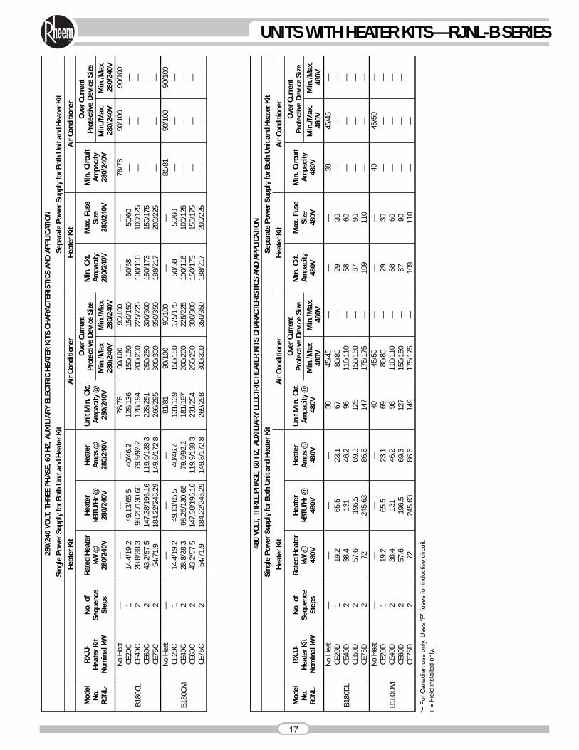
280/
240
VOLT
, THR
EE P
HASE
, 60
HZ, A
UXIL
IARY
ELE
CTRI
C HE
ATER
KIT
S CH
ARAC
TERI
STIC
S AN
D AP
PLIC
ATIO
NSi
ngle
Pow
er S
uppl
y fo
r Bot
h Un
it an
d He
ater
Kit
Sepa
rate
Pow
er S
uppl
y fo
r Bot
h Un
it an
d He
ater
Kit
Heat
er K
itAi
r Con
ditio
ner
Heat
er K
itAi
r Con
ditio
ner
Mod
elNo
.RJ
NL-
RXJJ
-He
ater
Kit
Nom
inal
kW
No. o
fSe
quen
ceSt
eps
Rate
d He
ater
kW @
280/
240V
Heat
erkB
TU/H
r @28
0/24
0V
Heat
erAm
ps @
280/
240V
Unit
Min
. Ckt
.Am
paci
ty @
280/
240V
Over
Cur
rent
Prot
ectiv
e De
vice
Siz
eM
in. C
kt.
Ampa
city
280/
240V
Max
. Fus
eSi
ze28
0/24
0V
Min
. Circ
uit
Ampa
city
280/
240V
Over
Cur
rent
Prot
ectiv
e De
vice
Siz
eM
in./M
ax28
0/24
0VM
in./M
ax.
280/
240V
Min
./Max
.28
0/24
0VM
in./M
ax.
280/
240V
B180
CL
No H
eat
——
——
78/7
890
/100
90/1
00—
—78
/78
90/1
0090
/100
CE20
C1
14.4
/19.
249
.13/
65.5
40/4
6.2
128/
136
150/
150
150/
150
50/5
850
/60
——
—CE
40C
228
.8/3
8.3
98.2
5/13
0.66
79.9
/92.
217
8/19
420
0/20
022
5/22
510
0/11
610
0/12
5—
——
CE60
C2
43.2
/57.
514
7.38
/196
.16
119.
9/13
8.3
228/
251
250/
250
300/
300
150/
173
150/
175
——
—CE
75C
254
/71.
918
4.22
/245
.29
149.
8/17
2.8
266/
295
300/
300
350/
350
188/
217
200/
225
——
—
B180
CM
No H
eat
——
——
81/8
190
/100
90/1
00—
—81
/81
90/1
0090
/100
CE20
C1
14.4
/19.
249
.13/
65.5
40/4
6.2
131/
139
150/
150
175/
175
50/5
850
/60
——
—CE
40C
228
.8/3
8.3
98.2
5/13
0.66
79.9
/92.
218
1/19
720
0/20
022
5/22
510
0/11
610
0/12
5—
——
CE60
C2
43.2
/57.
514
7.38
/196
.16
119.
9/13
8.3
231/
254
250/
250
300/
300
150/
173
150/
175
——
—CE
75C
254
/71.
918
4.22
/245
.29
149.
8/17
2.8
269/
298
300/
300
350/
350
188/
217
200/
225
——
—
480
VOLT
, THR
EE P
HASE
, 60
HZ, A
UXIL
IARY
ELE
CTRI
C HE
ATER
KIT
S CH
ARAC
TERI
STIC
S AN
D AP
PLIC
ATIO
NSi
ngle
Pow
er S
uppl
y fo
r Bot
h Un
it an
d He
ater
Kit
Sepa
rate
Pow
er S
uppl
y fo
r Bot
h Un
it an
d He
ater
Kit
Heat
er K
itAi
r Con
ditio
ner
Heat
er K
itAi
r Con
ditio
ner
Mod
elNo
.RJ
NL-
RXJJ
-He
ater
Kit
Nom
inal
kW
No. o
fSe
quen
ceSt
eps
Rate
d He
ater
kW @
480V
Heat
erkB
TU/H
r @48
0V
Heat
erAm
ps @
480V
Unit
Min
. Ckt
.Am
paci
ty @
480V
Over
Cur
rent
Prot
ectiv
e De
vice
Siz
eM
in. C
kt.
Ampa
city
480V
Max
. Fus
eSi
ze48
0V
Min
. Circ
uit
Ampa
city
480V
Over
Cur
rent
Prot
ectiv
e De
vice
Siz
eM
in./M
ax48
0VM
in./M
ax.
480V
Min
./Max
.48
0VM
in./M
ax.
480V
B180
DL
No H
eat
——
——
3845
/45
——
—38
45/4
5—
CE20
D1
19.2
65.5
23.1
6780
/80
—29
30—
——
CE40
D2
38.4
131
46.2
9611
0/11
0—
5860
——
—CE
60D
257
.619
6.5
69.3
125
150/
150
—87
90—
——
CE75
D2
7224
5.63
86.6
147
175/
175
—10
911
0—
——
B180
DM
No H
eat
——
——
4045
/50
——
—40
45/5
0—
CE20
D1
19.2
65.5
23.1
6980
/80
—29
30—
——
CE40
D2
38.4
131
46.2
9811
0/11
0—
5860
——
—CE
60D
257
.619
6.5
69.3
127
150/
150
—87
90—
——
CE75
D2
7224
5.63
86.6
149
175/
175
—10
911
0—
—
*= F
or C
anad
ian
use
only
. Use
s “P
” fu
ses
for
indu
ctiv
e ci
rcui
t.+
= F
ield
inst
alle
d on
ly.
17
UNITS WITH HEATER KITS—RJNL-B SERIES
18
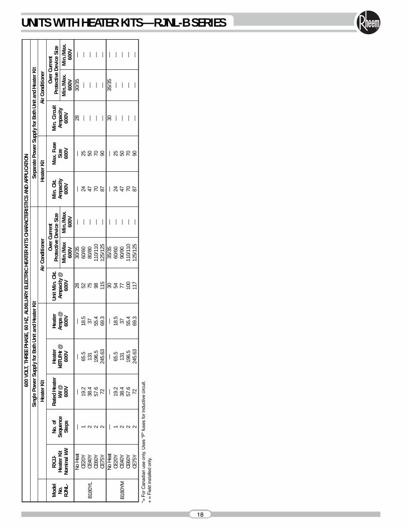
UNITS WITH HEATER KITS—RJNL-B SERIES60
0VO
LT, T
HREE
PHA
SE, 6
0 HZ
, AUX
ILIA
RY E
LECT
RIC
HEAT
ER K
ITS
CHAR
ACTE
RIST
ICS
AND
APPL
ICAT
ION
Sing
le P
ower
Sup
ply
for B
oth
Unit
and
Heat
er K
itSe
para
te P
ower
Sup
ply
for B
oth
Unit
and
Heat
er K
itHe
ater
Kit
Air C
ondi
tione
rHe
ater
Kit
Air C
ondi
tione
r
Mod
elNo
.RJ
NL-
RXJJ
-He
ater
Kit
Nom
inal
kW
No. o
fSe
quen
ceSt
eps
Rate
d He
ater
kW @
600V
Heat
erkB
TU/H
r @60
0V
Heat
erAm
ps @
600V
Unit
Min
. Ckt
.Am
paci
ty @
600V
Over
Cur
rent
Prot
ectiv
e De
vice
Siz
eM
in. C
kt.
Ampa
city
600V
Max
. Fus
eSi
ze60
0V
Min
. Circ
uit
Ampa
city
600V
Over
Cur
rent
Prot
ectiv
e De
vice
Siz
eM
in./M
ax60
0VM
in./M
ax.
600V
Min
./Max
.60
0VM
in./M
ax.
600V
B180
YL
No H
eat
——
——
2830
/35
——
—28
30/3
5—
CE20
Y1
19.2
65.5
18.5
5260
/60
—24
25—
——
CE40
Y2
38.4
131
3775
80/8
0—
4750
——
—CE
60Y
257
.619
6.5
55.4
9811
0/11
0—
7070
——
—CE
75Y
272
245.
6369
.311
512
5/12
5—
8790
——
—
B180
YM
No H
eat
——
——
3035
/35
——
—30
35/3
5—
CE20
Y1
19.2
65.5
18.5
5460
/60
—24
25—
——
CE40
Y2
38.4
131
3777
90/9
0—
4750
——
—CE
60Y
257
.619
6.5
55.4
100
110/
110
—70
70—
——
CE75
Y2
7224
5.63
69.3
117
125/
125
—87
90—
——
*= F
or C
anad
ian
use
only
. Use
s “P
” fu
ses
for
indu
ctiv
e ci
rcui
t.+
= F
ield
inst
alle
d on
ly.
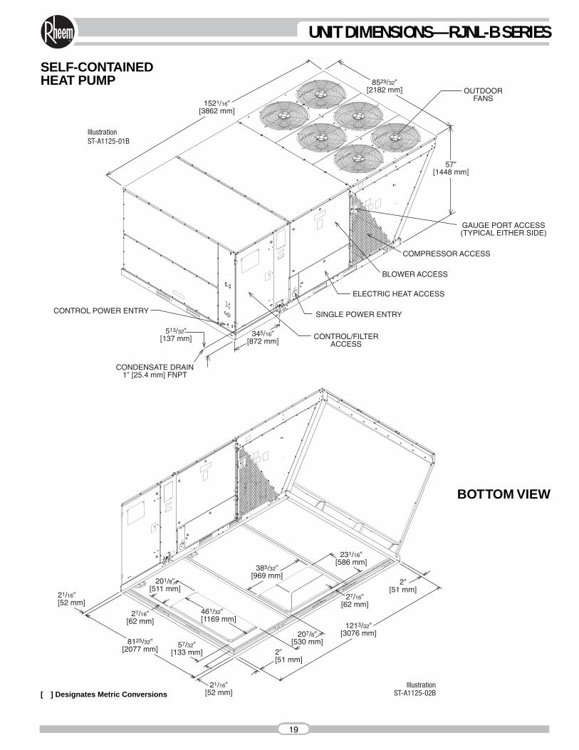
SELF-CONTAINEDHEAT PUMP
[ ] Designates Metric Conversions
BOTTOM VIEW
19
UNIT DIMENSIONS—RJNL-B SERIES
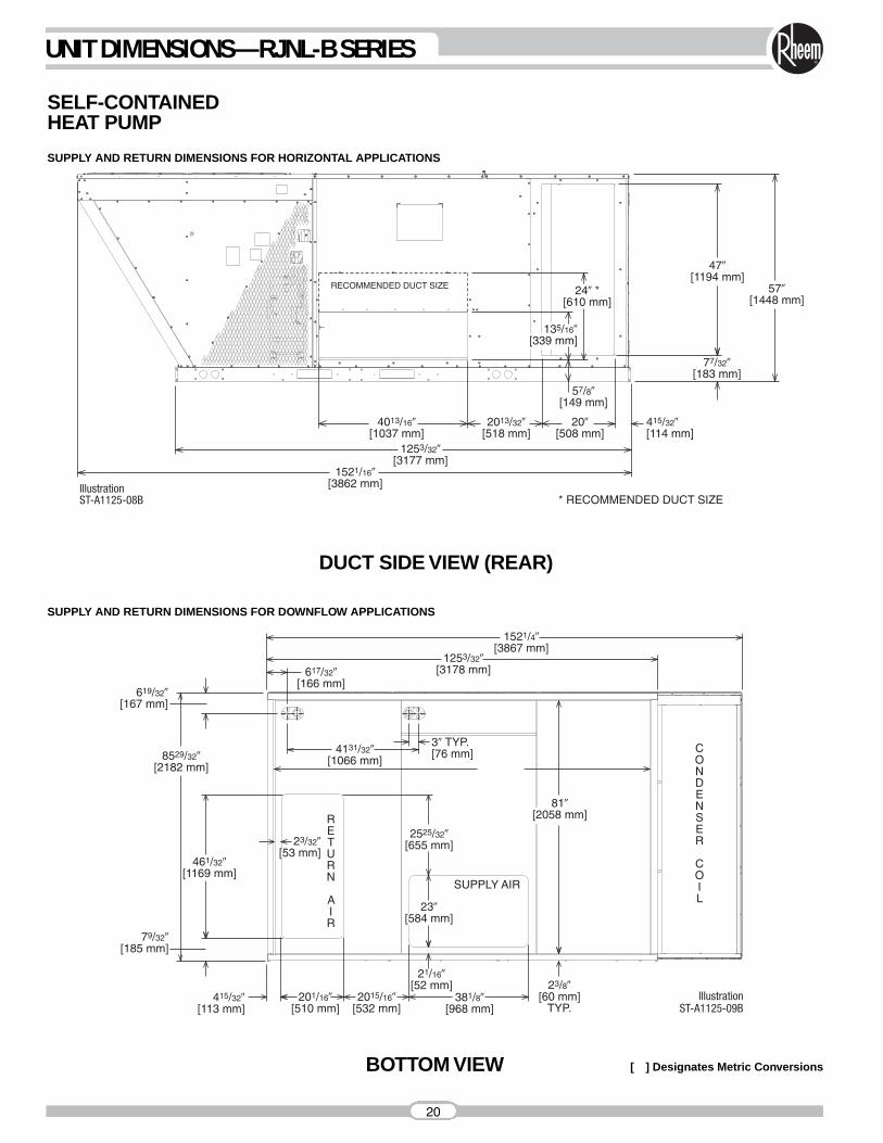
SUPPLY AND RETURN DIMENSIONS FOR DOWNFLOW APPLICATIONS
SUPPLY AND RETURN DIMENSIONS FOR HORIZONTAL APPLICATIONS
SELF-CONTAINEDHEAT PUMP
DUCT SIDE VIEW (REAR)
BOTTOM VIEW [ ] Designates Metric Conversions
20
UNIT DIMENSIONS—RJNL-B SERIES
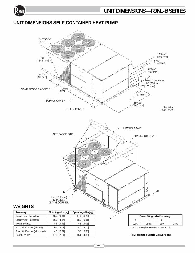
A B C D32% 27% 16% 24%
Corner Weights by Percentage
WEIGHTSAccessory Shipping—lbs [kg]Economizer–Downflow 155 [70.31]
Power Exhaust 44 [19.96]Fresh Air Damper (Manual) 51 [23.13] 40 [18.14]
42 [19.05]
146 [66.22]Operating—lbs [kg]
Fresh Air Damper (Motorized) 46 [20.87]Roof Curb 14" 170 [77.11] 164 [74.39]
35 [15.88]
Economizer–Horizontal 165 [74.84] 155 [70.31]
UNIT DIMENSIONS SELF-CONTAINED HEAT PUMP
*Note: Corner weights measured at base of unit.
[ ] Designates Metric Conversions
21
UNIT DIMENSIONS—RJNL-B SERIES
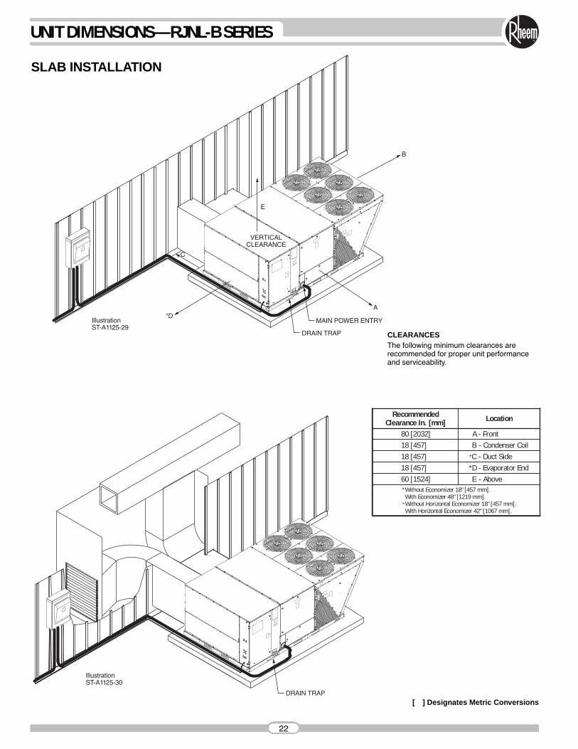
CLEARANCESThe following minimum clearances arerecommended for proper unit performanceand serviceability.
RecommendedClearance In. [mm] Location
80 [2032] *A - Front18 [457] *B - Condenser Coil18 [457] +C - Duct Side18 [457] *D - Evaporator End60 [1524] *E - Above*Without Economizer 18" [457 mm].With Economizer 48" [1219 mm].
+ Without Horizontal Economizer 18" [457 mm].With Horizontal Economizer 42" [1067 mm].
SLAB INSTALLATION
[ ] Designates Metric Conversions
22
UNIT DIMENSIONS—RJNL-B SERIES
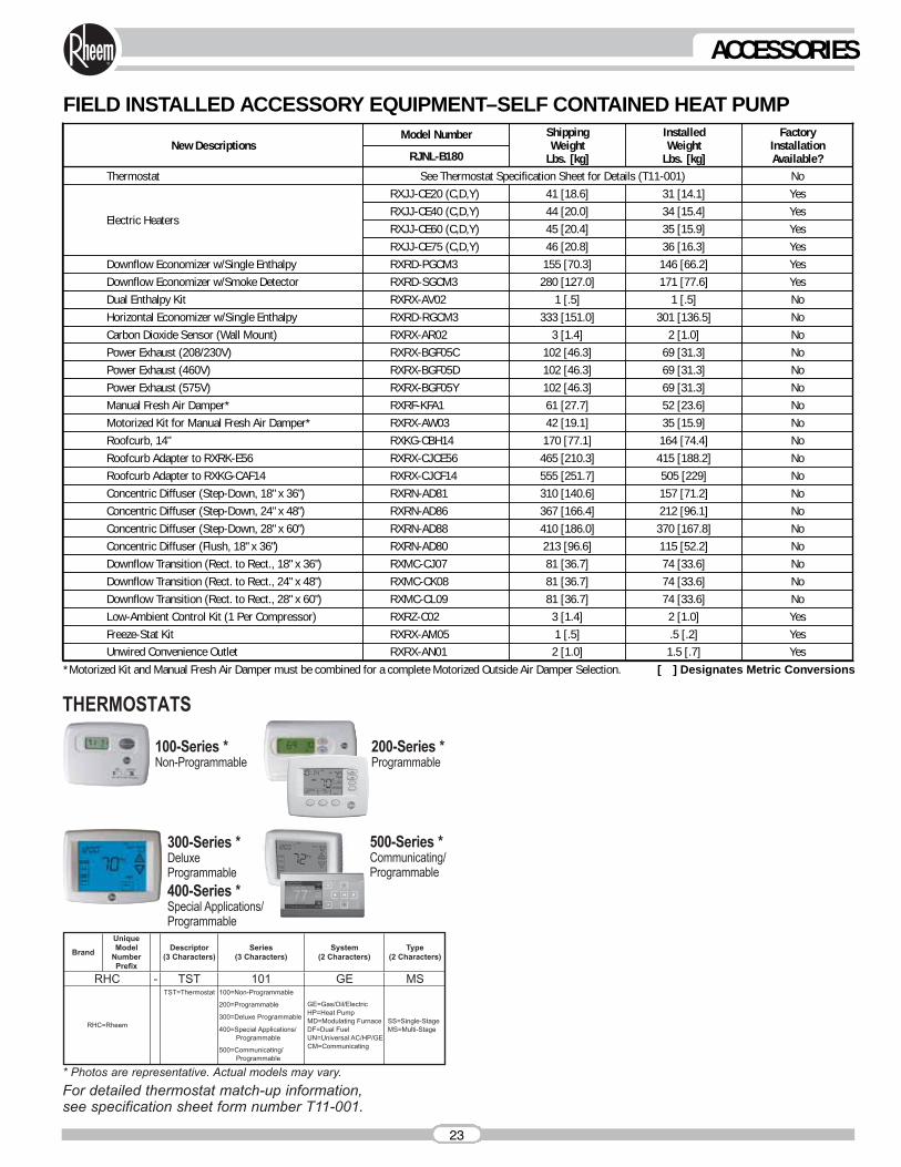
FIELD INSTALLED ACCESSORY EQUIPMENT–SELF CONTAINED HEAT PUMP
New DescriptionsModel Number Installed
WeightLbs. [kg]
Electric Heaters
RXJJ-CE20 (C,D,Y) 31 [14.1]
Downflow Economizer w/Single Enthalpy RXRD-PGCM3 146 [66.2]
Carbon Dioxide Sensor (Wall Mount) RXRX-AR02 2 [1.0]Power Exhaust (208/230V) RXRX-BGF05C 69 [31.3]
Manual Fresh Air Damper* RXRF-KFA1 52 [23.6]
ShippingWeight
Lbs. [kg]
41 [18.6]
155 [70.3]
3 [1.4]102 [46.3]
61 [27.7]
FactoryInstallationAvailable?
Yes
Yes
NoNo
NoMotorized Kit for Manual Fresh Air Damper* RXRX-AW03 42 [19.1] 35 [15.9] NoRoofcurb, 14" RXKG-CBH14 170 [77.1] 164 [74.4] NoRoofcurb Adapter to RXRK-E56 RXRX-CJCE56 465 [210.3] 415 [188.2] No
Concentric Diffuser (Step-Down, 18" x 36") RXRN-AD81 310 [140.6] 157 [71.2] NoConcentric Diffuser (Step-Down, 24" x 48") RXRN-AD86 367 [166.4] 212 [96.1] NoConcentric Diffuser (Step-Down, 28" x 60") RXRN-AD88 410 [186.0] 370 [167.8] NoConcentric Diffuser (Flush, 18" x 36") RXRN-AD80 213 [96.6] 115 [52.2] NoDownflow Transition (Rect. to Rect., 18" x 36") RXMC-CJ07 81 [36.7] 74 [33.6] NoDownflow Transition (Rect. to Rect., 24" x 48") RXMC-CK08 81 [36.7] 74 [33.6] NoDownflow Transition (Rect. to Rect., 28" x 60") RXMC-CL09 81 [36.7] 74 [33.6] NoLow-Ambient Control Kit (1 Per Compressor) RXRZ-C02 3 [1.4] 2 [1.0] YesFreeze-Stat Kit RXRX-AM05 1 [.5] .5 [.2] Yes
45 [20.4] YesRXJJ-CE60 (C,D,Y) 35 [15.9]44 [20.0] YesRXJJ-CE40 (C,D,Y) 34 [15.4]
46 [20.8] YesRXJJ-CE75 (C,D,Y) 36 [16.3]
Horizontal Economizer w/Single Enthalpy 333 [151.0] NoRXRD-RGCM3 301 [136.5]1 [.5] NoDual Enthalpy Kit RXRX-AV02 1 [.5]
Thermostat See Thermostat Specification Sheet for Details (T11-001) No
RJNL-B180
280 [127.0] YesDownflow Economizer w/Smoke Detector RXRD-SGCM3 171 [77.6]
102 [46.3] NoPower Exhaust (460V) RXRX-BGF05D 69 [31.3]102 [46.3] NoPower Exhaust (575V) RXRX-BGF05Y 69 [31.3]
Roofcurb Adapter to RXKG-CAF14 RXRX-CJCF14 555 [251.7] 505 [229] No
Unwired Convenience Outlet RXRX-AN01 2 [1.0] 1.5 [.7] Yes*Motorized Kit and Manual Fresh Air Damper must be combined for a complete Motorized Outside Air Damper Selection. [ ] Designates Metric Conversions
23
ACCESSORIES
[ ] Designates Metric Conversions
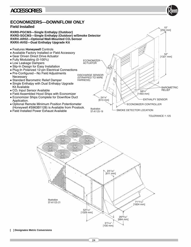
■ Features Honeywell Controls■ Available Factory Installed or Field Accessory■ Gear Driven Direct Drive Actuator■ Fully Modulating (0-100%)■ Low Leakage Dampers■ Slip-In Design for Easy Installation■ Plug-In Polarized 12-pin Electrical Connections■ Pre-Configured—No Field Adjustments
Necessary■ Standard Barometric Relief Damper■ Single Enthalpy with Dual Enthalpy Upgrade
Kit Available■ CO2 Input Sensor Available■ Field Assembled Hood Ships with Economizer■ Economizer Ships Complete for Downflow Duct
Application.■ Optional Remote Minimum Position Potentiometer
(Honeywell #S963B1128) is Available from Prostock.■ Field Installed Power Exhaust Available
ECONOMIZERS—DOWNFLOW ONLYField InstalledRXRD-PGCM3—Single Enthalpy (Outdoor) RXRD-SGCM3—Single Enthalpy (Outdoor) w/Smoke DetectorRXRX-AR02—Optional Wall-Mounted CO2 SensorRXRX-AV02—Dual Enthalpy Upgrade Kit
24
ACCESSORIES
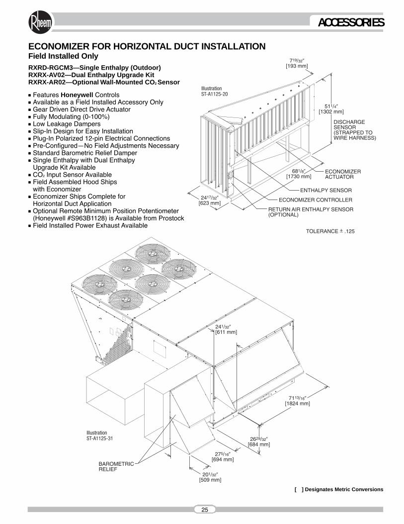
ECONOMIZER FOR HORIZONTAL DUCT INSTALLATIONField Installed OnlyRXRD-RGCM3—Single Enthalpy (Outdoor)RXRX-AV02—Dual Enthalpy Upgrade KitRXRX-AR02—Optional Wall-Mounted CO2 Sensor
■ Features Honeywell Controls■ Available as a Field Installed Accessory Only■ Gear Driven Direct Drive Actuator■ Fully Modulating (0-100%)■ Low Leakage Dampers■ Slip-In Design for Easy Installation■ Plug-In Polarized 12-pin Electrical Connections■ Pre-Configured—No Field Adjustments Necessary■ Standard Barometric Relief Damper■ Single Enthalpy with Dual Enthalpy
Upgrade Kit Available■ CO2 Input Sensor Available■ Field Assembled Hood Ships
with Economizer■ Economizer Ships Complete for
Horizontal Duct Application■ Optional Remote Minimum Position Potentiometer
(Honeywell #S963B1128) is Available from Prostock■ Field Installed Power Exhaust Available
[ ] Designates Metric Conversions
25
ACCESSORIES
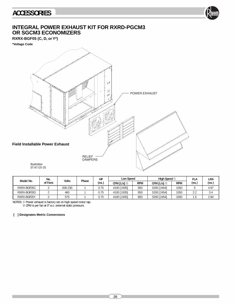
INTEGRAL POWER EXHAUST KIT FOR RXRD-PGCM3 OR SGCM3 ECONOMIZERSRXRX-BGF05 (C, D, or Y*)*Voltage Code
Field Installable Power Exhaust
Model No. No.of Fans Volts Phase HP
(ea.)Low Speed
RXRX-BGF05C 2 208-230 1 0.75 4100 [1935] 850 5200 [2454]
High Speed ➀
1050 5
FLA(ea.)
4.97
LRA(ea.)
RXRX-BGF05D 2 460 1 0.75 4100 [1935] 850 5200 [2454] 1050 2.2 3.4RXRX-BGF05Y 2 575 1 0.75 4100 [1935] 850 5200 [2454] 1050 1.5 2.84
CFM [L/s] ➁ RPM CFM [L/s] ➁ RPM
NOTES: ➀ Power exhaust is factory set on high speed motor tap.➁ CFM is per fan at 0" w.c. external static pressure.
[ ] Designates Metric Conversions
26
ACCESSORIES
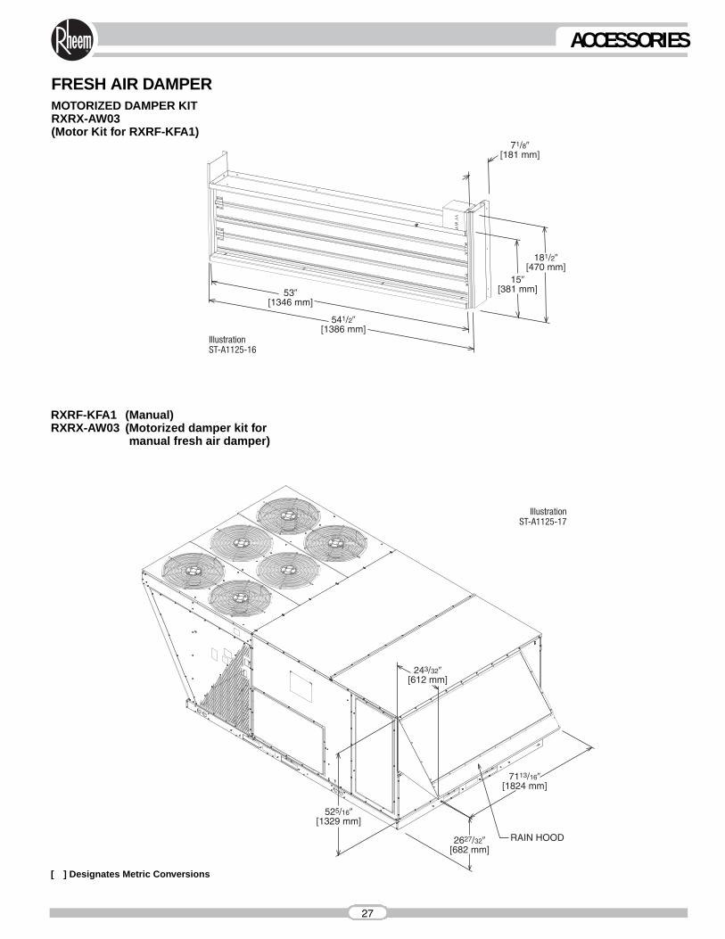
FRESH AIR DAMPERMOTORIZED DAMPER KITRXRX-AW03(Motor Kit for RXRF-KFA1)
[ ] Designates Metric Conversions
RXRF-KFA1 (Manual)RXRX-AW03 (Motorized damper kit for
manual fresh air damper)
27
ACCESSORIES
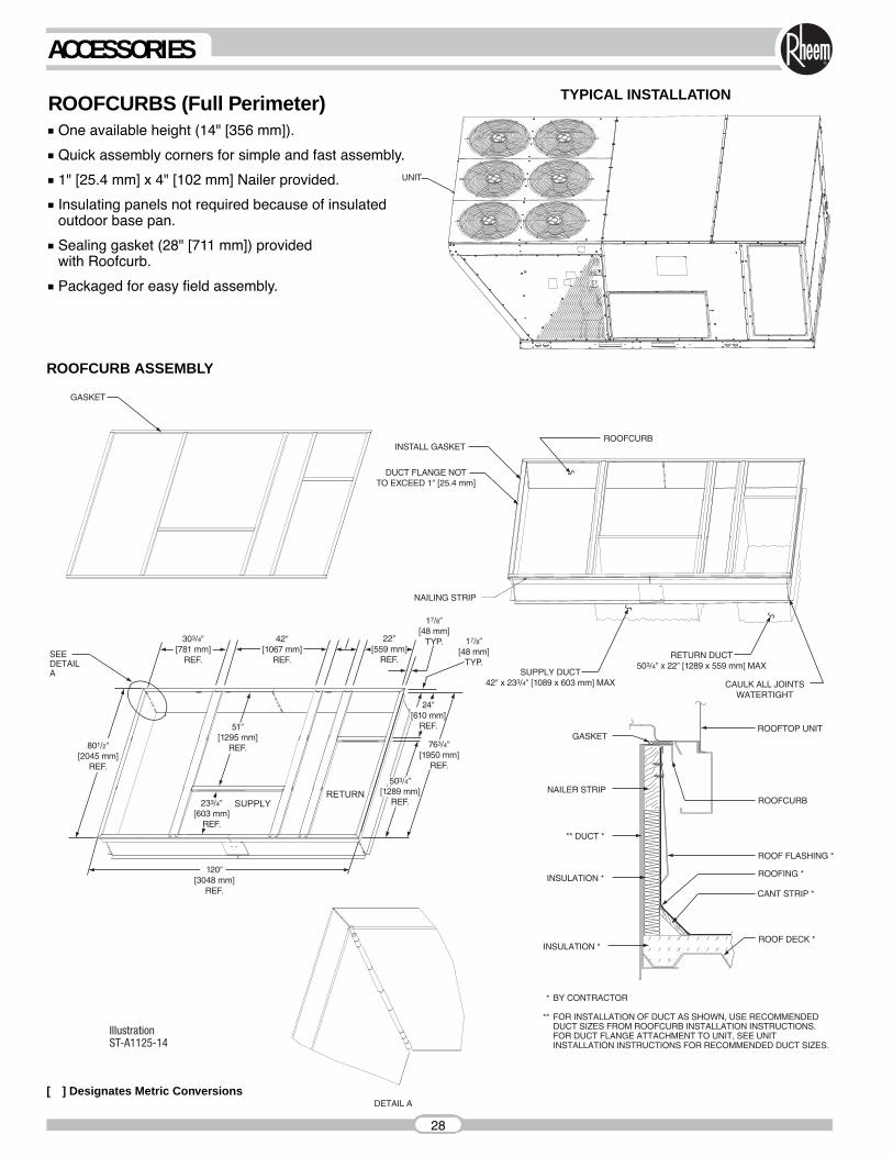
ROOFCURBS (Full Perimeter)■ One available height (14" [356 mm]).
■ Quick assembly corners for simple and fast assembly.
■ 1" [25.4 mm] x 4" [102 mm] Nailer provided.
■ Insulating panels not required because of insulated outdoor base pan.
■ Sealing gasket (28" [711 mm]) providedwith Roofcurb.
■ Packaged for easy field assembly.
[ ] Designates Metric Conversions
ROOFCURB ASSEMBLY
UNIT
28
ACCESSORIES
TYPICAL INSTALLATION
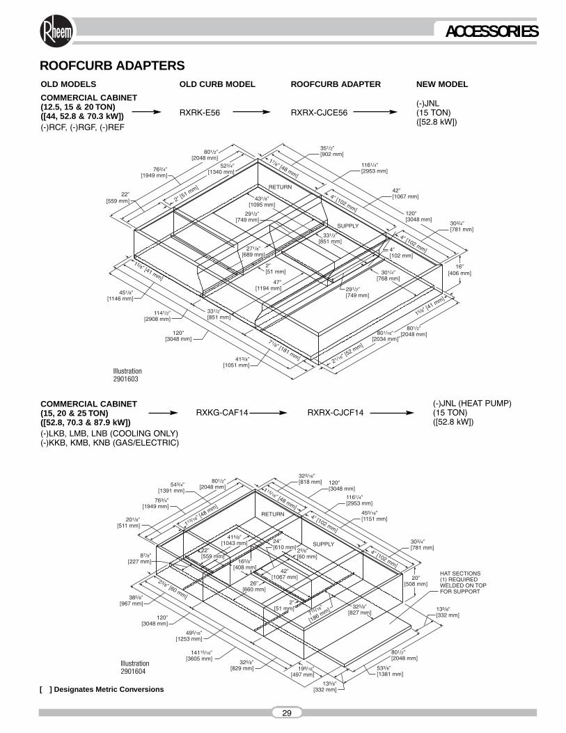
ROOFCURB ADAPTERS
[ ] Designates Metric Conversions
NEW MODEL
(-)JNL(15 TON)([52.8 kW])
OLD MODELS OLD CURB MODEL ROOFCURB ADAPTER
COMMERCIAL CABINET (12.5, 15 & 20 TON)([44, 52.8 & 70.3 kW])(-)RCF, (-)RGF, (-)REF
RXRK-E56 RXRX-CJCE56
(-)JNL (HEAT PUMP)(15 TON)([52.8 kW])
COMMERCIAL CABINET (15, 20 & 25 TON)([52.8, 70.3 & 87.9 kW])(-)LKB, LMB, LNB (COOLING ONLY)(-)KKB, KMB, KNB (GAS/ELECTRIC)
RXKG-CAF14 RXRX-CJCF14
29
ACCESSORIES
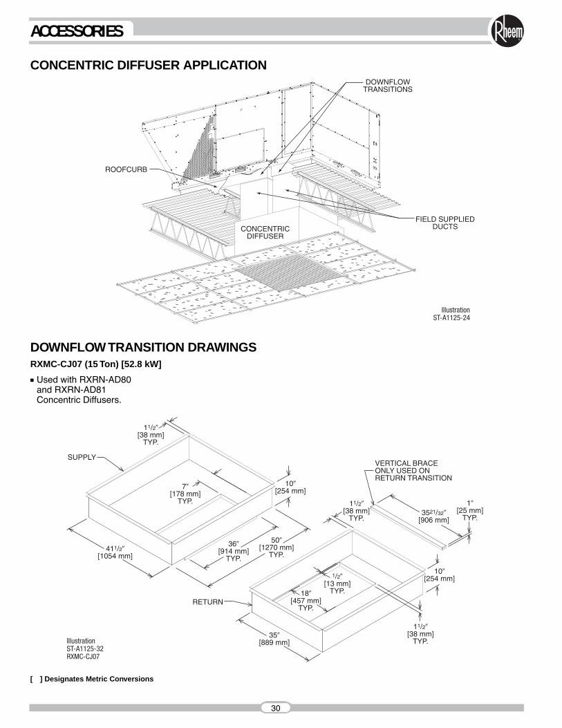
CONCENTRIC DIFFUSER APPLICATION
DOWNFLOW TRANSITION DRAWINGSRXMC-CJ07 (15 Ton) [52.8 kW]
■ Used with RXRN-AD80and RXRN-AD81Concentric Diffusers.
[ ] Designates Metric Conversions
30
ACCESSORIES

CONCENTRIC DIFFUSER SPECIFICATIONS
CONCENTRIC DIFFUSER15 TON [52.8 kW] FLUSH■ All aluminum diffuser with aluminum
return air eggcrate.
■ Built-in anti-sweat gasket.
■ Molded fiberglass supports.
■ Built-in hanging supports.
■ Diffuser box constructed of sheetmetalinsulated with 1" [25.4 mm] 1.5 lbs. [.7 kg] duct liner.
PARTNUMBER CFM [L/s] STATIC
PRESSURETHROW
FEET
5800 [2737] 0.39 29-386000 [2832] 0.42 40-50
RXRN-AD80
5600 [2643] 0.36 28-37
107110361000
NECKVELOCITY
223021562082
JETVELOCITY
6200 [2926] 0.46 42-51 1107 23086400 [3020] 0.50 43-52 1143 23796600 [3115] 0.54 45-56 1179 2454
[ ] Designates Metric Conversions
31
ACCESSORIES
CONCENTRIC DIFFUSER SPECIFICATIONS
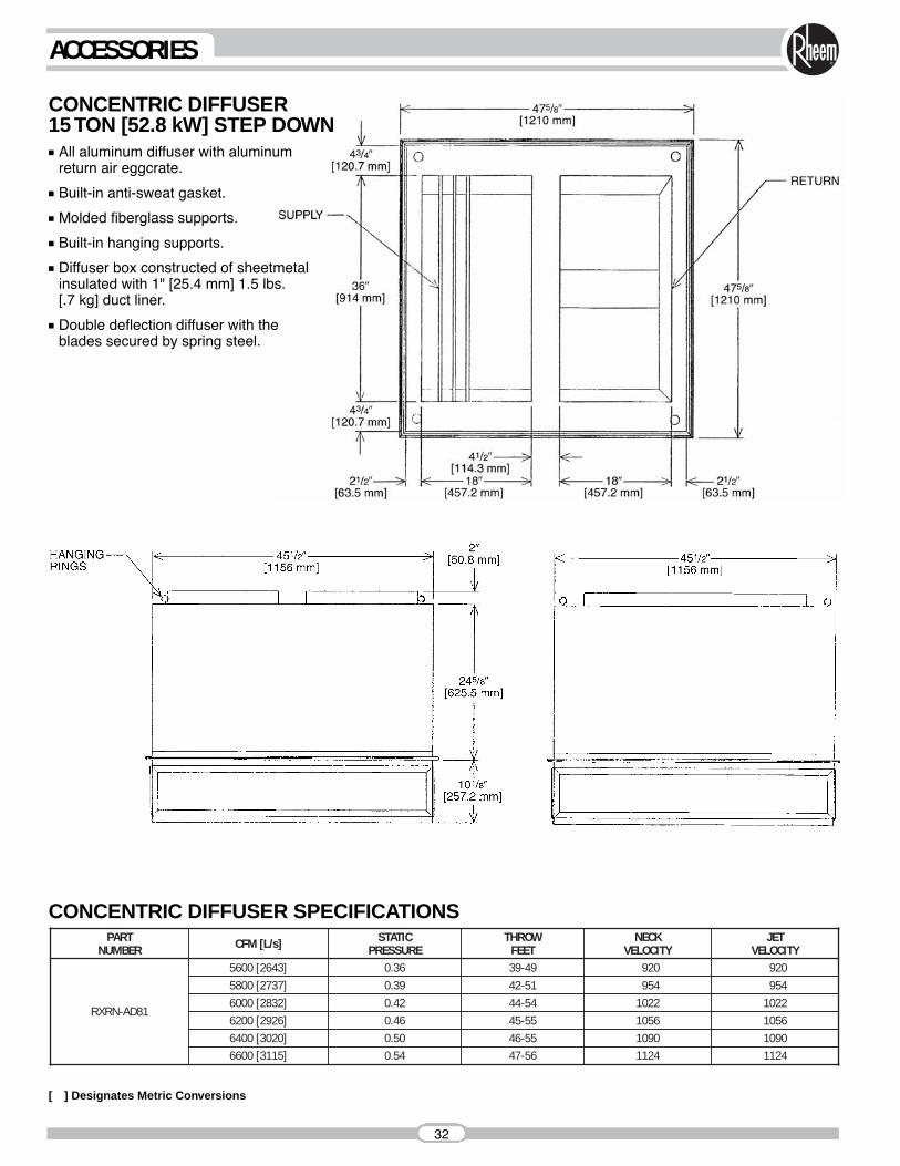
CONCENTRIC DIFFUSER15 TON [52.8 kW] STEP DOWN■ All aluminum diffuser with aluminum
return air eggcrate.
■ Built-in anti-sweat gasket.
■ Molded fiberglass supports.
■ Built-in hanging supports.
■ Diffuser box constructed of sheetmetal insulated with 1" [25.4 mm] 1.5 lbs.[.7 kg] duct liner.
■ Double deflection diffuser with theblades secured by spring steel.
PARTNUMBER CFM [L/s] STATIC
PRESSURETHROW
FEET
1022954920
NECKVELOCITY
1022954920
JETVELOCITY
6200 [2926] 0.46 45-55 1056 10566400 [3020] 0.50 46-55 1090 10906600 [3115]
5800 [2737] 0.39 42-51
0.54 47-56 1124 1124
6000 [2832] 0.42 44-54RXRN-AD81
5600 [2643] 0.36 39-49
[ ] Designates Metric Conversions
32
ACCESSORIES
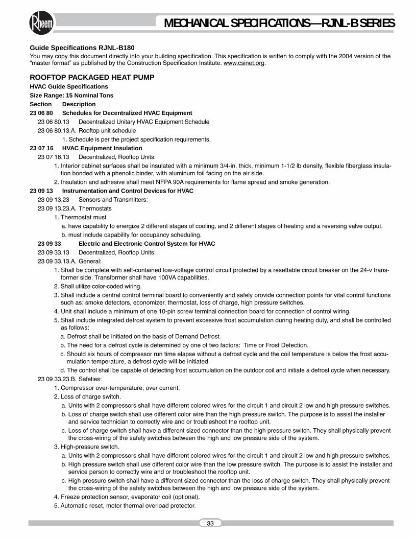
Guide Specifications RJNL-B180You may copy this document directly into your building specification. This specification is written to comply with the 2004 version of the“master format” as published by the Construction Specification Institute. www.csinet.org.
ROOFTOP PACKAGED HEAT PUMPHVAC Guide SpecificationsSize Range: 15 Nominal TonsSection Description23 06 80 Schedules for Decentralized HVAC Equipment
23 06 80.13 Decentralized Unitary HVAC Equipment Schedule23 06 80.13.A. Rooftop unit schedule
1. Schedule is per the project specification requirements.23 07 16 HVAC Equipment Insulation
23 07 16.13 Decentralized, Rooftop Units:1. Interior cabinet surfaces shall be insulated with a minimum 3/4-in. thick, minimum 1-1/2 lb density, flexible fiberglass insula-
tion bonded with a phenolic binder, with aluminum foil facing on the air side.2. Insulation and adhesive shall meet NFPA 90A requirements for flame spread and smoke generation.
23 09 13 Instrumentation and Control Devices for HVAC23 09 13.23 Sensors and Transmitters:23 09 13.23.A. Thermostats
1. Thermostat musta. have capability to energize 2 different stages of cooling, and 2 different stages of heating and a reversing valve output.b. must include capability for occupancy scheduling.
23 09 33 Electric and Electronic Control System for HVAC23 09 33.13 Decentralized, Rooftop Units:23 09 33.13.A. General:
1. Shall be complete with self-contained low-voltage control circuit protected by a resettable circuit breaker on the 24-v trans-former side. Transformer shall have 100VA capabilities.
2. Shall utilize color-coded wiring.3. Shall include a central control terminal board to conveniently and safely provide connection points for vital control functions
such as: smoke detectors, economizer, thermostat, loss of charge, high pressure switches.4. Unit shall include a minimum of one 10-pin screw terminal connection board for connection of control wiring.5. Shall include integrated defrost system to prevent excessive frost accumulation during heating duty, and shall be controlled
as follows:a. Defrost shall be initiated on the basis of Demand Defrost.b. The need for a defrost cycle is determined by one of two factors: Time or Frost Detection.c. Should six hours of compressor run time elapse without a defrost cycle and the coil temperature is below the frost accu-
mulation temperature, a defrost cycle will be initiated.d. The control shall be capable of detecting frost accumulation on the outdoor coil and initiate a defrost cycle when necessary.
23 09 33.23.B. Safeties:1. Compressor over-temperature, over current.2. Loss of charge switch.
a. Units with 2 compressors shall have different colored wires for the circuit 1 and circuit 2 low and high pressure switches.b. Loss of charge switch shall use different color wire than the high pressure switch. The purpose is to assist the installer
and service technician to correctly wire and or troubleshoot the rooftop unit.c. Loss of charge switch shall have a different sized connector than the high pressure switch. They shall physically prevent
the cross-wiring of the safety switches between the high and low pressure side of the system.3. High-pressure switch.
a. Units with 2 compressors shall have different colored wires for the circuit 1 and circuit 2 low and high pressure switches.b. High pressure switch shall use different color wire than the low pressure switch. The purpose is to assist the installer and
service person to correctly wire and or troubleshoot the rooftop unit.c. High pressure switch shall have a different sized connector than the loss of charge switch. They shall physically prevent
the cross-wiring of the safety switches between the high and low pressure side of the system.4. Freeze protection sensor, evaporator coil (optional).5. Automatic reset, motor thermal overload protector.
33
MECHANICAL SPECIFICATIONS—RJNL-B SERIES

23 09 93 Sequence of Operations for HVAC Controls23 09 93.13 Decentralized, Rooftop Units:23 09 93.13 INSERT SEQUENCE OF OPERATION23 40 13 Panel Air Filters23 40 13.13 Decentralized, Rooftop Units:23 40 13.13.A. Standard filter section shall
1. Shall consist of factory-installed, low velocity, throwaway 2-in. thick fiberglass filters of commercially available sizes. 2. Filters shall be accessible through an access panel as described in the unit cabinet section of this specification
(23 81 19.13.H).23 81 19 Self-Contained Air Conditioners
23 81 19.13 Small-Capacity Self-Contained Air Conditioners23 81 19.13.A. General
1. Outdoor, rooftop mounted, electrically controlled, heating and cooling unit utilizing a(n) hermetic scroll compressor(s) forcooling duty and heat pump for heating duty.
2. Factory assembled, single-piece heating and cooling rooftop unit. Contained within the unit enclosure shall be all factorywiring, piping, controls, and special features required prior to field start-up.
3. Unit shall use environmentally sound R-410a refrigerant.4. Unit shall be installed in accordance with the manufacturerʼs instructions.5. Unit must be selected and installed in compliance with local, state, and federal codes.
23 81 19.13.B. Quality Assurance1. Unit meets ASHRAE 90.1-2007 minimum efficiency requirements.2. 3 phase units are Energy Star qualified.3. Unit shall be rated in accordance with AHRI Standards 210/240 and 340/360.4. Unit shall be designed to conform to ASHRAE 15, 2001.5. Unit shall be UL-tested and certified in accordance with ANSI Z21.47 Standards and UL-listed and certified under Cana-
dian standards as a total package for safety requirements.6. Insulation and adhesive shall meet NFPA 90A requirements for flame spread and smoke generation.7. Unit casing shall be capable of withstanding 500-hour salt spray exposure per ASTM B117 (scribed specimen).8. Unit casing shall be capable of withstanding Federal Test Method Standard No. 141 (Method 6061) 5000-hour salt spray.9. Unit shall be designed in accordance with ISO 9001:2000, and shall be manufactured in a facility registered by ISO
9001:2000.10. Roof curb shall be designed to conform to NRCA Standards.11. Unit shall be subjected to a completely automated run test on the assembly line. The data for each unit will be stored at
the factory, and must be available upon request.12. Unit shall be designed in accordance with UL Standard 1995, including tested to withstand rain.13. Unit shall be constructed to prevent intrusion of snow and tested to prevent snow intrusion into the control box up to
40 mph.23 81 19.13.C.Delivery, Storage, and Handling
1. Unit shall be stored and handled per manufacturerʼs recommendations.2. Lifted by crane requires either shipping top panel or spreader bars.3. Unit shall only be stored or positioned in the upright position.
23 81 19.13.E. Project Conditions1. As specified in the contract.
23 81 19.13.F. Operating Characteristics1. Unit shall be capable of starting and running at 115ºF (46ºC) ambient outdoor temperature, meeting maximum load criteria
of AHRI Standard 210/240 or 340/360 at ± 10% voltage.2. Compressor with standard controls shall be capable of operation from 40ºF (4ºC) , ambient outdoor temperatures. Acces-
sory low ambient kit is necessary if mechanically cooling at ambient temperatures below 40ºF (4ºC).3. Unit shall be capable of simultaneous heating duty and defrost cycle operation when using accessory electric heaters.4. Unit shall discharge supply air vertically or horizontally as shown on contract drawings.5. Unit shall be factory configured for vertical supply & return configurations.6. Unit shall be field convertible from vertical to horizontal configuration.
23 81 19.13.G.Electrical Requirements1. Main power supply voltage, phase, and frequency must match those required by the manufacturer.
34
MECHANICAL SPECIFICATIONS—RJNL-B SERIES
23 81 19.13.H.Unit Cabinet1. Unit cabinet shall be constructed of galvanized steel, and shall be bonderized and coated with a baked enamel finish on all
externally exposed surfaces.2. Unit cabinet exterior paint shall be: film thickness, (dry) 0.003 inches minimum, gloss (per ASTM D523, 60ºF): 60, Hard-
ness: H-2H Pencil hardness.3. Evaporator fan compartment interior cabinet insulation shall conform to AHRI Standards 210/240 or 340/360 minimum
exterior sweat criteria. Interior surfaces shall be insulated with a minimum 3/4-in. thick, 1 lb density, flexible fiberglass insulation, aluminum foil-faced on the air side.
4. Base of unit shall have locations for thru-the-base electrical connections (factory installed or field installed), standard.5. Base Rail
a. Unit shall have base rails on all sides.b. Holes shall be provided in the base rails for rigging shackles to facilitate maneuvering and overhead rigging.c. Holes shall be provided in the base rail for moving the rooftop by fork truck.d. Base rail shall be a minimum of 14 gauge thickness.
6. Condensate pan and connections:a. Shall be a sloped condensate drain pan made of a non-corrosive material.b. Shall comply with ASHRAE Standard 62. c. Shall use a 1" -11 1/2 NPT drain connection, through the side of the drain pan. Connection shall be made per manufac-
turerʼs recommendations.7. Electrical Connections
a. All unit power wiring shall enter unit cabinet at a single, factory-prepared, knockout location.b. Thru-the-base capability
(1) Standard unit shall have a thru-the-base electrical location(s) using a raised, embossed portion of the unit basepan.(2) No basepan penetration, other than those authorized by the manufacturer, is permitted.
8. Component access panels (standard)a. Cabinet panels shall be easily removable for servicing.b. Stainless steel metal hinges are standard on all doors.c. Panels covering control box, indoor fan, indoor fan motor, and electric or gas heater components (where applicable),
shall have ¼ turn latches.23 81 19.13.J. Coils
1. Standard Aluminum/Copper Coils: on all models.a. Standard evaporator and condenser coils shall have aluminum lanced plate fins mechanically bonded to seamless
internally grooved copper tubes with all joints brazed.b. Evaporator and Condenser coils shall be leak tested to 150 psig, pressure tested to 550 psig, and qualified to UL 1995
burst test at 2,200 psig. 23 81 19.13.K. Refrigerant Components
1. Refrigerant circuit shall include the following control, safety, and maintenance features:a. Thermal Expansion Valve (TXV) with venturi type distributor.b. Refrigerant filter drier.c. External service gauge connections to unit suction and discharge lines.
2. Compressorsa. Unit shall use one fully hermetic, scroll compressor for each independent refrigeration circuit.b. Compressor motors shall be cooled by refrigerant gas passing through motor windings.d. Compressors shall be internally protected from high discharge temperature conditions.e. Compressors shall be protected from an over-temperature and over-amperage conditions by an internal, motor over-
load device.f. Compressor shall be factory mounted on rubber grommets.g. Compressor motors shall have internal line break thermal, current overload and high pressure differential protection.h. Crankcase heaters shall be utilized on all models to protect compressor with specific refrigerant charge.
23 81 19.13.L. Filter Section1. Filters access is specified in the unit cabinet section of this specification.2. Filters shall be held in place by a sliding filter tray, facilitating easy removal and installation.3. Shall consist of factory-installed, low velocity, throw-away 2-in. thick fiberglass filters.4. Filters shall be standard, commercially available sizes.5. Filter face velocity shall not exceed 365 fpm at nominal airflows.
35
MECHANICAL SPECIFICATIONS—RJNL-B SERIES
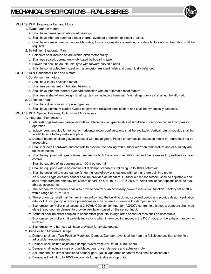
23 81 19.13.M. Evaporator Fan and Motor1. Evaporator fan motor:
a. Shall have permanently lubricated bearings.b. Shall have inherent automatic-reset thermal overload protection or circuit breaker.c. Shall have a maximum continuous bhp rating for continuous duty operation; no safety factors above that rating shall be
required.2. Belt-driven Evaporator Fan:
a. Belt drive shall include an adjustable-pitch motor pulley.b. Shall use sealed, permanently lubricated ball-bearing type.c. Blower fan shall be double-inlet type with forward-curved blades.d. Shall be constructed from steel with a corrosion resistant finish and dynamically balanced.
23 81 19.13.N.Condenser Fans and Motors1. Condenser fan motors:
a. Shall be a totally enclosed motor.b. Shall use permanently lubricated bearings.c. Shall have inherent thermal overload protection with an automatic reset feature.d. Shall use a shaft-down design. Shaft-up designs including those with “rain-slinger devices” shall not be allowed.
2. Condenser Fans:a. Shall be a direct-driven propeller type fan.b. Shall have aluminum blades riveted to corrosion-resistant steel spiders and shall be dynamically balanced.
23 81 19.13.O. Special Features, Options and Accessories1. Integrated Economizers:
a. Integrated, gear-driven parallel modulating blade design type capable of simultaneous economizer and compressoroperation.
b. Independent modules for vertical or horizontal return configurations shall be available. Vertical return modules shall beavailable as a factory installed option.
c. Damper blades shall be galvanized steel with metal gears. Plastic or composite blades on intake or return shall not beacceptable.
d. Shall include all hardware and controls to provide free cooling with outdoor air when temperature and/or humidity arebelow setpoints.
e. Shall be equipped with gear driven dampers for both the outdoor ventilation air and the return air for positive air streamcontrol.
f. Shall be capable of introducing up to 100% outdoor air.g. Shall be equipped with a barometric relief damper capable of relieving up to 100% return air.h. Shall be designed to close damper(s) during loss-of-power situations with spring return built into motor.i. An outdoor single enthalpy sensor shall be provided as standard. Outdoor air sensor setpoint shall be adjustable and
shall range from the enthalpy equivalent of 63°F @ 50% rh to 73°F @ 50% rh. Additional sensor options shall be avail-able as accessories.
j. The economizer controller shall also provide control of an accessory power exhaust unit function. Factory set at 70%,with a range of 0% to 100%.
k. The economizer shall maintain minimum airflow into the building during occupied period and provide design ventilationrate for full occupancy. A remote potentiometer may be used to override the damper setpoint.
l. Economizer controller shall accept a 2-10Vdc CO2 sensor input for IAQ/DCV control. In this mode, dampers shall mod-ulate the outdoor-air damper to provide ventilation based on the sensor input.
m. Actuator shall be direct coupled to economizer gear. No linkage arms or control rods shall be acceptable. n. Economizer controller shall provide indications when in free cooling mode, in the DCV mode, or the exhaust fan contact
is closed. o. Economizer wire harness will have provision for smoke detector.
2. Two-Position Motorized Dampera. Damper shall be a Two-Position Motorized Damper. Damper travel shall be from the full closed position to the field
adjustable %-open setpoint.b. Damper shall include adjustable damper travel from 25% to 100% (full open).c. Damper shall include single or dual blade, gear driven dampers and actuator motor. d. Actuator shall be direct coupled to damper gear. No linkage arms or control rods shall be acceptable.e. Damper will admit up to 100% outdoor air for applicable rooftop units.
36
MECHANICAL SPECIFICATIONS—RJNL-B SERIES
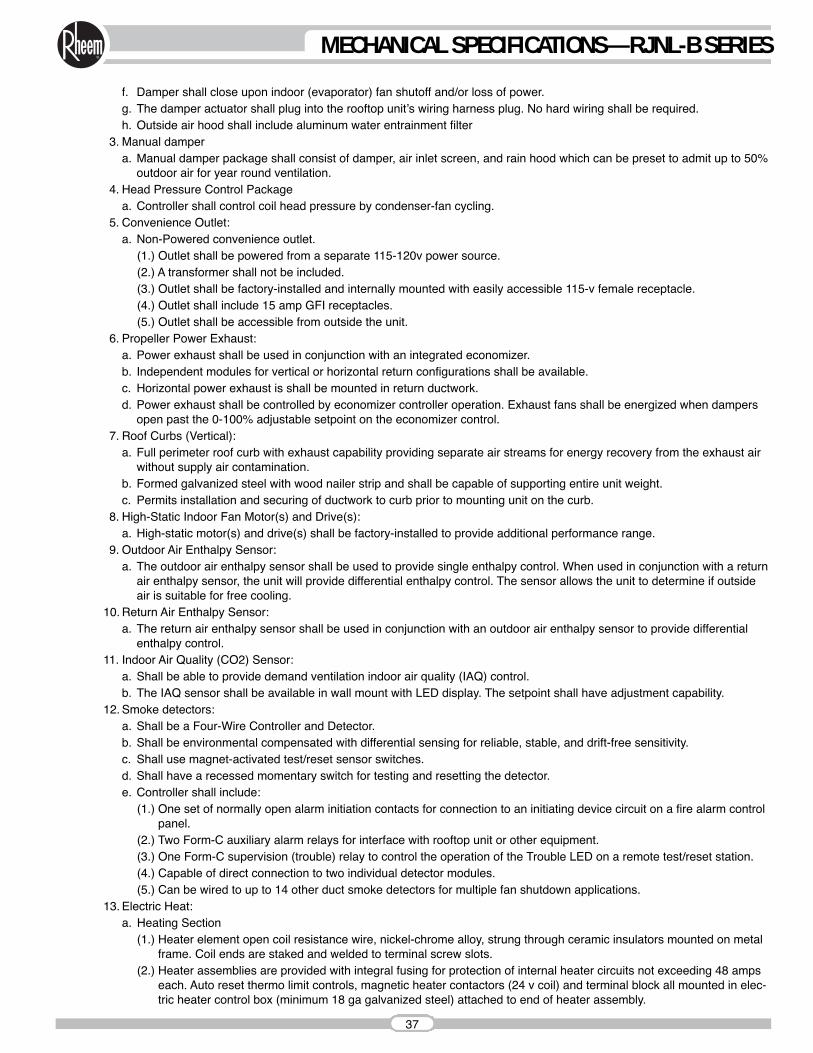
f. Damper shall close upon indoor (evaporator) fan shutoff and/or loss of power.g. The damper actuator shall plug into the rooftop unitʼs wiring harness plug. No hard wiring shall be required.h. Outside air hood shall include aluminum water entrainment filter
3. Manual dampera. Manual damper package shall consist of damper, air inlet screen, and rain hood which can be preset to admit up to 50%
outdoor air for year round ventilation.4. Head Pressure Control Package
a. Controller shall control coil head pressure by condenser-fan cycling.5. Convenience Outlet:
a. Non-Powered convenience outlet.(1.) Outlet shall be powered from a separate 115-120v power source.(2.) A transformer shall not be included.(3.) Outlet shall be factory-installed and internally mounted with easily accessible 115-v female receptacle.(4.) Outlet shall include 15 amp GFI receptacles. (5.) Outlet shall be accessible from outside the unit.
6. Propeller Power Exhaust:a. Power exhaust shall be used in conjunction with an integrated economizer. b. Independent modules for vertical or horizontal return configurations shall be available.c. Horizontal power exhaust is shall be mounted in return ductwork.d. Power exhaust shall be controlled by economizer controller operation. Exhaust fans shall be energized when dampers
open past the 0-100% adjustable setpoint on the economizer control. 7. Roof Curbs (Vertical):
a. Full perimeter roof curb with exhaust capability providing separate air streams for energy recovery from the exhaust airwithout supply air contamination.
b. Formed galvanized steel with wood nailer strip and shall be capable of supporting entire unit weight.c. Permits installation and securing of ductwork to curb prior to mounting unit on the curb.
8. High-Static Indoor Fan Motor(s) and Drive(s):a. High-static motor(s) and drive(s) shall be factory-installed to provide additional performance range.
9. Outdoor Air Enthalpy Sensor:a. The outdoor air enthalpy sensor shall be used to provide single enthalpy control. When used in conjunction with a return
air enthalpy sensor, the unit will provide differential enthalpy control. The sensor allows the unit to determine if outsideair is suitable for free cooling.
10. Return Air Enthalpy Sensor:a. The return air enthalpy sensor shall be used in conjunction with an outdoor air enthalpy sensor to provide differential
enthalpy control.11. Indoor Air Quality (CO2) Sensor:
a. Shall be able to provide demand ventilation indoor air quality (IAQ) control.b. The IAQ sensor shall be available in wall mount with LED display. The setpoint shall have adjustment capability.
12. Smoke detectors:a. Shall be a Four-Wire Controller and Detector.b. Shall be environmental compensated with differential sensing for reliable, stable, and drift-free sensitivity.c. Shall use magnet-activated test/reset sensor switches.d. Shall have a recessed momentary switch for testing and resetting the detector.e. Controller shall include:
(1.) One set of normally open alarm initiation contacts for connection to an initiating device circuit on a fire alarm controlpanel.
(2.) Two Form-C auxiliary alarm relays for interface with rooftop unit or other equipment.(3.) One Form-C supervision (trouble) relay to control the operation of the Trouble LED on a remote test/reset station.(4.) Capable of direct connection to two individual detector modules.(5.) Can be wired to up to 14 other duct smoke detectors for multiple fan shutdown applications.
13. Electric Heat:a. Heating Section
(1.) Heater element open coil resistance wire, nickel-chrome alloy, strung through ceramic insulators mounted on metalframe. Coil ends are staked and welded to terminal screw slots.
(2.) Heater assemblies are provided with integral fusing for protection of internal heater circuits not exceeding 48 ampseach. Auto reset thermo limit controls, magnetic heater contactors (24 v coil) and terminal block all mounted in elec-tric heater control box (minimum 18 ga galvanized steel) attached to end of heater assembly.
37
MECHANICAL SPECIFICATIONS—RJNL-B SERIES
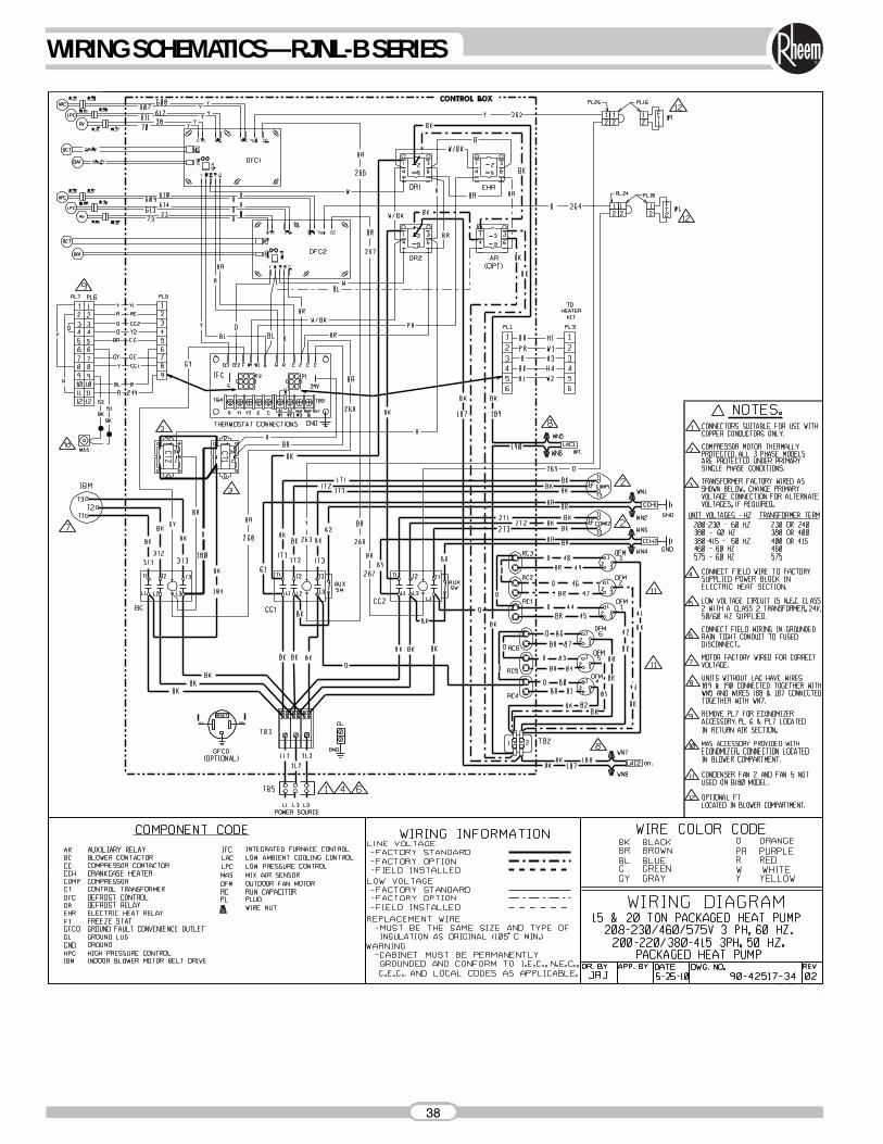
38
WIRING SCHEMATICS—RJNL-B SERIES
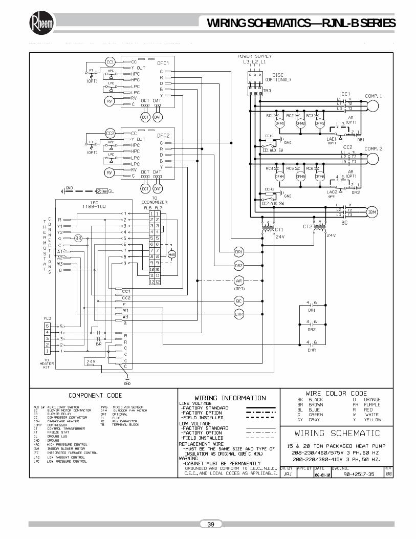
39
WIRING SCHEMATICS—RJNL-B SERIES

GENERAL TERMS OF LIMITED WARRANTYRheem will furnish a replacement for any part of this productwhich fails in normal use and service within the applicableperiods stated, in accordance with the terms of the limited warranty.
For Complete Details of the Limited Warranty, Including Applicable Termsand Conditions, See Your Local Installer or Contact the Manufacturer fora Copy.
Compressor .......................................................Five (5) YearsElectric Resistance Heater Elements ................Five (5) YearsAny Other Part................................................One (1) Year
BEFORE PURCHASING THIS APPLIANCE, READ IMPORTANT ENERGY COST AND EFFICIENCY INFORMATION AVAILABLE FROMYOUR RETAILER.
Before proceeding with installation, referto installation instructions packagedwith each model, as well as complyingwith all Federal, State, Provincial, andLocal codes, regulations, and practices.
Rheem Heating,Cooling andWater Heating
P.O. Box 17010, Fort Smith, AR 72917
“In keeping with its policy of continuous progress and product improvement, Rheem reserves the right to make changes without notice.”
PRINTED IN U.S.A. 12-10 DC FORM NO. S11-943Supersedes Form No. S11-943
![SELF-CONTAINED HEAT PUMP PACKAGE UNITSpts.myrheem.com/.../PackPump/[-]QNJ/RQNJ_P11-762_Rev6.pdf · 2008-06-18 · form no. p11-762 rev. 6 supersedes form no. p11-762 rev. 5 rqnj-](https://img.pdfslide.net/doc/110x75/5e6a49cfa8c4444f763ec1b4/self-contained-heat-pump-package-qnjrqnjp11-762rev6pdf-2008-06-18-form.jpg)

![Package Heat Pump Units Convertible Models … Centrales/2 a 5...Package Heat Pump Units Convertible Models ... Filter Frame (WCZ060F) (2-16x25x2) BAYFLTR019A[ ] Lifting Lug Kit BAYLlFT002A[](https://img.pdfslide.net/doc/110x75/5aa7895d7f8b9ad31c8c0ed3/package-heat-pump-units-convertible-models-centrales2-a-5package-heat-pump.jpg)