Embed Size (px)
Citation preview

GroupBrad Bauer (Team Leader)Mohamud JamaTim DirksAbdiqani SidowKomlavi Dagban_A
Paving Machine Inclination Sensor
Faculty Advisor: Prof John SartoriIndustry Mentor: Rick Bergenheier

Overview● Introduction● Design Specs● Design
○ Analog Design○ Software Design○ PCB Design
● Design Verification● Customer Feedback● Conclusion● Questions
Brad
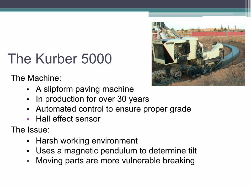
The Kurber 5000The Machine:
• A slipform paving machine• In production for over 30 years• Automated control to ensure proper grade• Hall effect sensor
The Issue:• Harsh working environment• Uses a magnetic pendulum to determine tilt • Moving parts are more vulnerable breaking
The Concept
Can we design a more robust sensor?• Eliminates moving parts• Works with current control system• Easy to install and calibrate
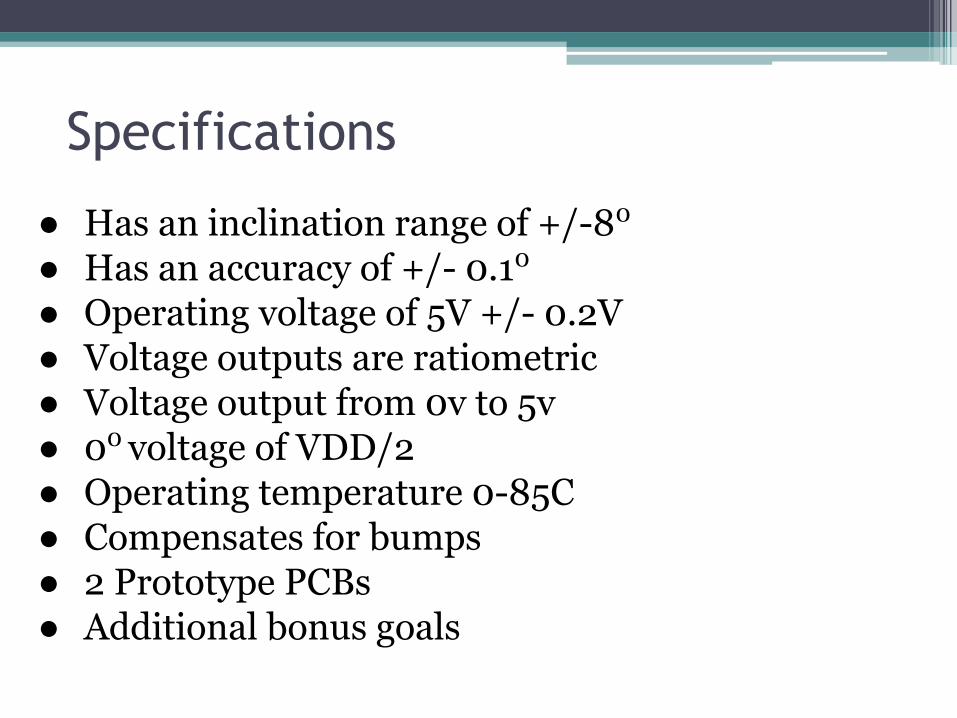
Specifications
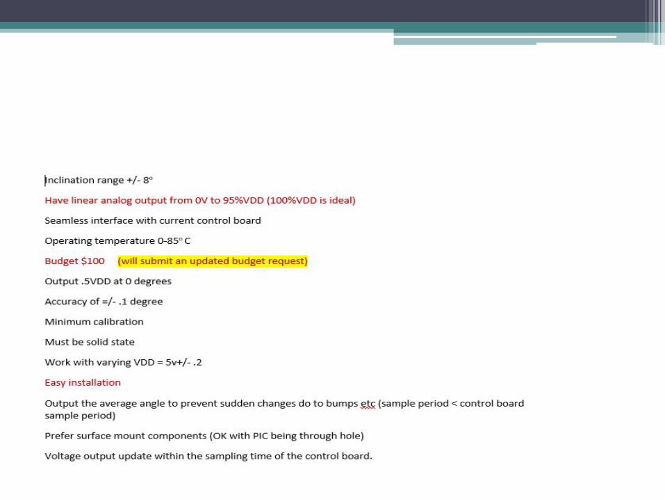
● Has an inclination range of +/-80
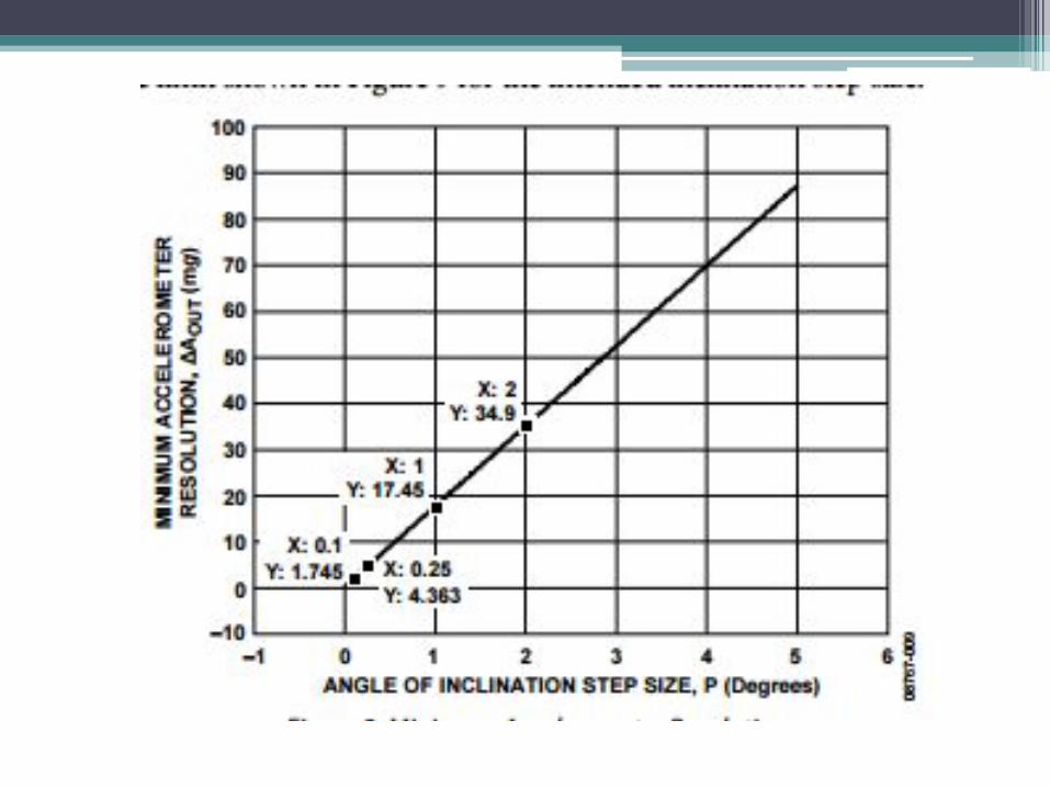
● Has an accuracy of +/- 0.10
● Operating voltage of 5V +/- 0.2V● Voltage outputs are ratiometric ● Voltage output from 0v to 5v● 00 voltage of VDD/2● Operating temperature 0-85C● Compensates for bumps● 2 Prototype PCBs● Additional bonus goals
Challenges Faced
● Source impedance too large for ADC ● Non-linear voltage follower output● Eeprom writing for permanent offset storage● Surface mounted components● Understanding the concept of the sensor

Overview● Introduction● Design Specs● Design
○ Analog Design○ Software Design○ PCB Design
● Design Verification● Customer Feedback● Conclusion● Questions
Abdi
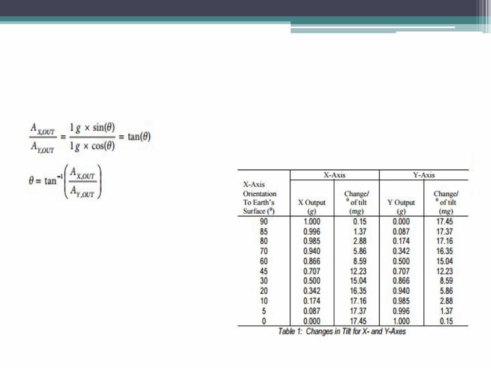
Accelerometer
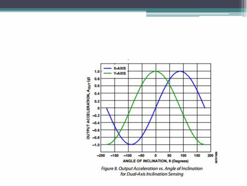
● Two-Axis acceleration reading● Accelerations may be static like gravity
or dynamic as motion or vibration● Outputs analog voltage for each axis

Analog Circuit Design● DC signal only signal of use● Design low pass filter that provides 0.5 hz cutoff frequency● Low pass filter can as simple as RC circuit between
accelerometer output and ADC● Voltage follower implementation● Voltage inverter to ensure voltage follower output is linear

Overview● Introduction● Design Specs● Design
○ Analog Design○ Software Design○ PCB Design
● Design Verification● Customer Feedback● Conclusion● Questions
Mohamud
• We selected PIC24FV16KM202 • Operating voltage 2 to 5v• 12 bit ADC
• Fine enough resolution to discern voltage changes from the accelerometer
• 8 bit DAC• Output can scale at least 0.1° angle changes.
• Wide range of interfaces including I²C, SPI, USB, UART
Software Design: Microcontroller
Microcontroller
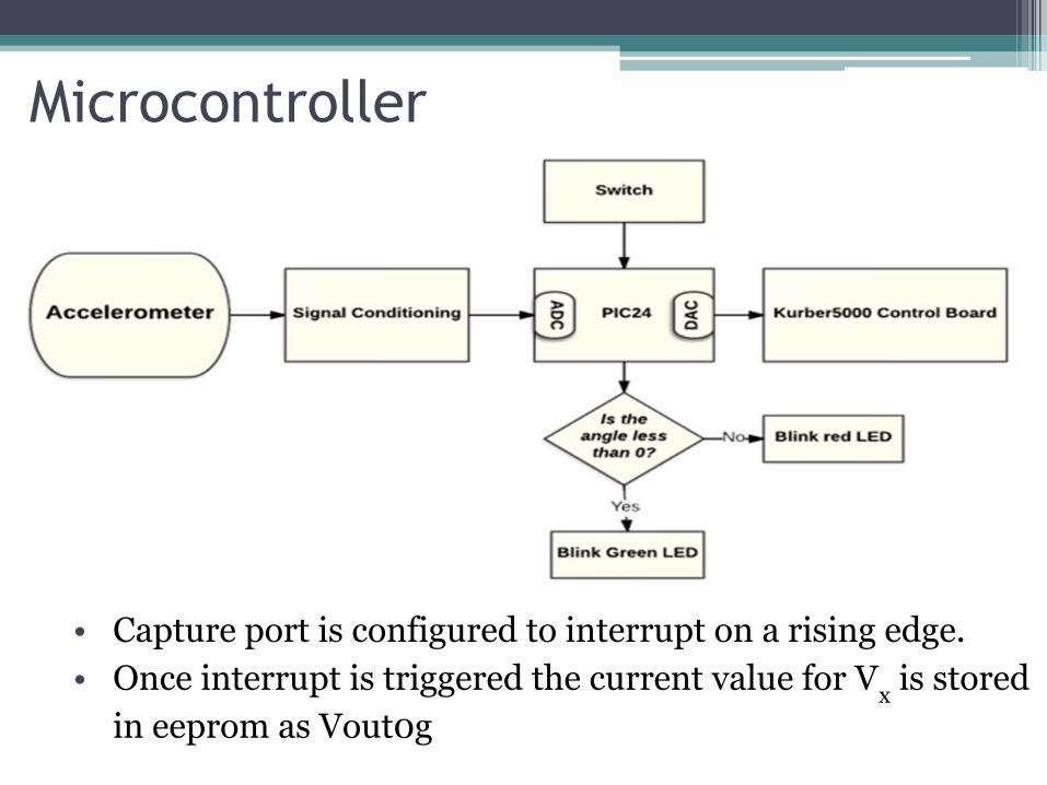
• Capture port is configured to interrupt on a rising edge. • Once interrupt is triggered the current value for Vx is stored
in eeprom as Vout0g
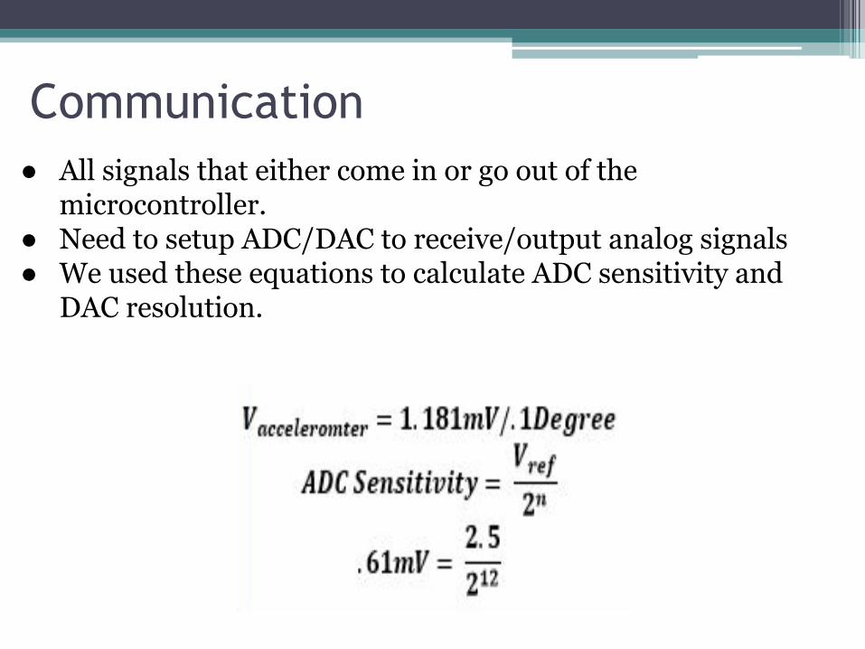
Communication● All signals that either come in or go out of the
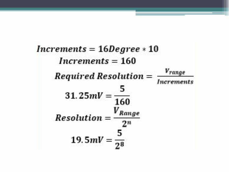
microcontroller.● Need to setup ADC/DAC to receive/output analog signals ● We used these equations to calculate ADC sensitivity and
DAC resolution.
ADC/DAC Setup• Setup ADC to samples of the X and Y channels.• Each sample takes 14*TAD = 62.5uS• The ADC samples until ADC buffer is full (16 samples).
• This gives a sample frequency of 7.142kHz. • The average of each channel is taken (8 samples each). • This oversampling and averaging also acts as a LPF• Variable passed to DAC Data and outputs per data sheet • Variable = angle*16+128, which gives the desired output
voltage per angle. It is also ratiometric
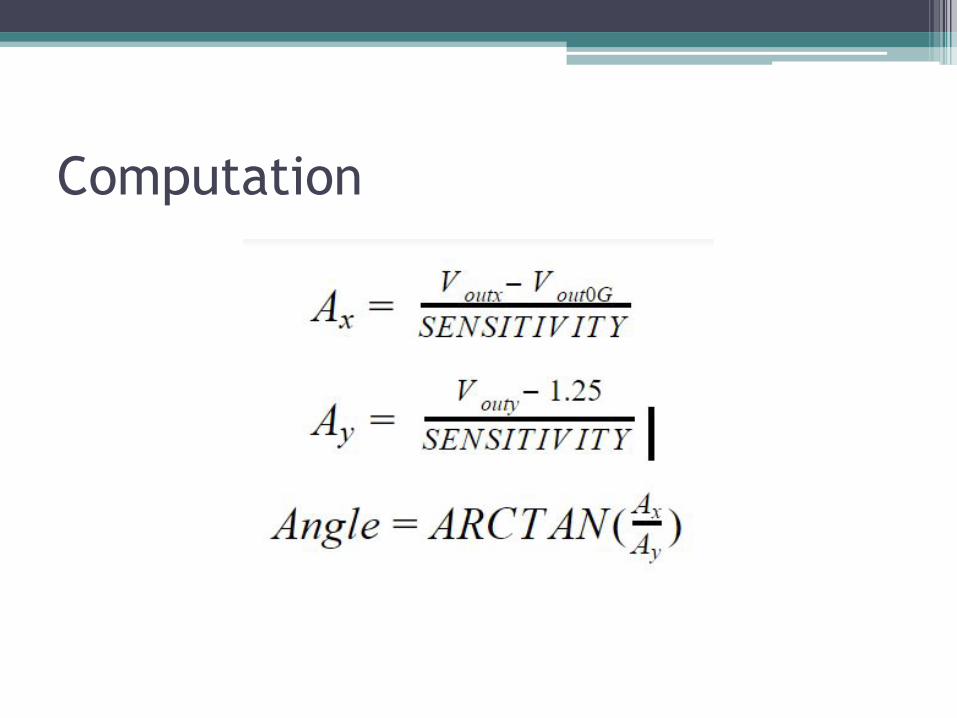
Computation

Overview● Introduction● Design Specs● Design
○ Analog Design○ Software Design○ PCB Design
● Design Verification● Customer Feedback● Conclusion● Questions
Tim
PCB Design
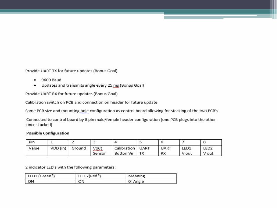
● Same Dimension as control board● Inputs: Power, Calibration offset● Outputs:
○ Analog○ Digital UART output via RS232
● Header for interface with control board● On-board switch and LEDs
○ Indicates + or - with blinking indication
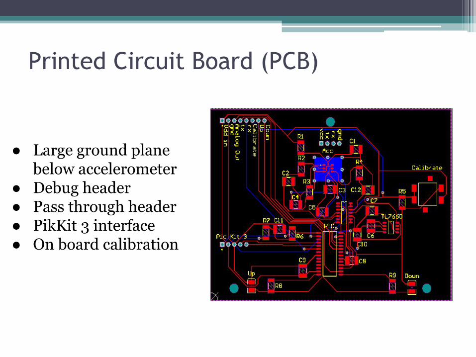
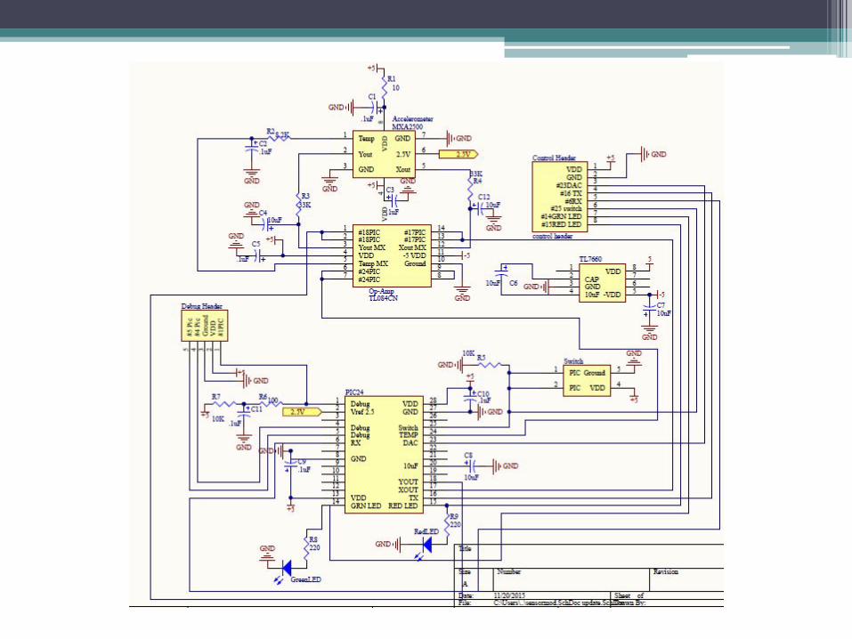
Printed Circuit Board (PCB)
● Large ground plane below accelerometer
● Debug header● Pass through header● PikKit 3 interface ● On board calibration

Overview● Introduction● Design Specs● Design
○ Analog Design○ Software Design○ PCB Design
● Design Verification● Customer Feedback● Conclusion● Questions
Komlavi
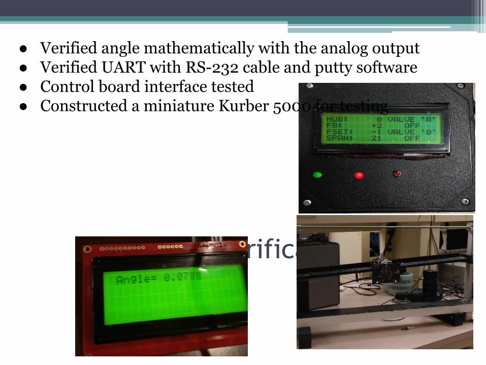
Design Verification
● Verified angle mathematically with the analog output● Verified UART with RS-232 cable and putty software● Control board interface tested● Constructed a miniature Kurber 5000 for testing

Customer Feedback
“Just finished my initial evaluation. The device appears to function
exactly as intended, good work.”
-Rick Bergenheier

Overview● Introduction● Design Specs● Design
○ Analog Design○ Software Design○ PCB Design
● Design Verification● Customer Feedback● Conclusion● Questions
Brad
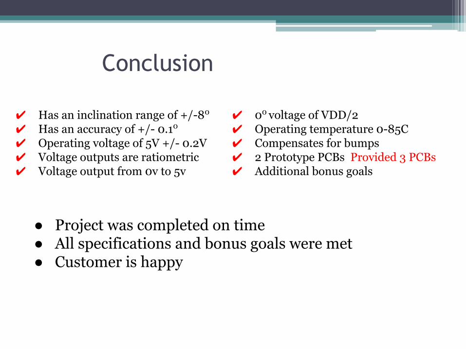
Conclusion
✔ 00 voltage of VDD/2✔ Operating temperature 0-85C✔ Compensates for bumps✔ 2 Prototype PCBs Provided 3 PCBs✔ Additional bonus goals
● Project was completed on time● All specifications and bonus goals were met● Customer is happy
✔ Has an inclination range of +/-80
✔ Has an accuracy of +/- 0.10
✔ Operating voltage of 5V +/- 0.2V✔ Voltage outputs are ratiometric ✔ Voltage output from 0v to 5v

Thank You
Questions???

2. Organizational Structure
● Brad Bauer - Team Leader, Accelerometer Specialist, Device Testing.
● Mohamud Jama - Software Communications and device selection.
● Tim Dirks - Software Algorithm and PCB verification.
● Abdiqani Sidow - Analog circuit and filtering.
● Komlavi Dagban-A - Primary PCB design.

3. Description of Individual Responsibilities● Brad Bauer - Team Leader, Simulations, Parts Sourcing, and Accelerometer: Provide
assistance with implementing the software code to interpret accelerometer readings, the digital interface with the microcontroller, and orientation on the PCB. Built final display fixture.
● Mohamud Jama - Software Communication: Develop code allowing for ADC and DAC communications with a resolution within design specs.
● Tim Dirks - Software Computation: Develop code for converting the output accelerometer values into inclination readings with temperature and zero g offset compensation.
● Abdiqani Sidow - Filter Design and Power Management: Design filters that provide a 1 Hz cutoff frequency while regulating current draw from the accelerometer. Ensure standard power management practices are implemented and created Gant Chart
● Komlavi Dagban-A - PCB Board Design: Develop a printed circuit board with correct footprints and proper traces that conform with suggested practices in the individual component's data sheet.