Embed Size (px)
Citation preview

1
Abstract—This paper describes a new generation of circuit breakers which take the old dead tank concept and by using the latest vacuum interruption devices and sealing technology brigs the concept uo tp date as a solution to the outdoor circuit breaker needs for the 21st century. This includes an all welded, sealed for life construction and highly reliable spring mechanism.
Index Terms—Circuit breakers, Environmental factors, Industrial power systems, Power distribution, Power distribution reliability, Power system reliability, Reliability, Vacuum circuit breakers.
I. INTRODUCTION oday dog-house designs for outdoor switchgear tend to be favoured due to the combination of competitive
prices together with ease of design, manufacture, and maintenance as compared to the older Oil based dead tank designs. However doghouse designs also suffer from a number of significant limitations which include large dimensions coupled with a tendency to be maintenance intensive, with the internal components exposed to ambient conditions (moisture, pollution, etc) In particular, doghouses are not arc-fault withstand tested.
The problem was how to overcome the limitations of the doghouse concept while meeting the modern expectations of the deregulated energy utilities which include reduced operation costs, improved availability and life expectancy, predictability of performance/life in service. In addition utilities today insist on type testing being carried out to latest international standards to reduce risk exposure (protection of people, seismic withstand, etc), and most importantly internal arc-fault containment to the latest standards
The result of this research is a new range of dead tank circuit breakers based on our extensive experience in the key technologies of vacuum interrupter design, actuator design, sealed for life welded construction, and our deep understanding of internal arc-fault withstand problems and solutions. This has allowed the new VOX and VPR (Vacuum Pole-mounted Recloser) ranges to combine the latest technologies and technical requirements with a cost-effective solution, creating the next generation of MV dead tank circuit breakers and reclosers. The concepts of both families are similar, but this paper will concentrate on the VOX Circuit Breaker family.
II. THE CONCEPT
Fig. 1. VOX 38kV dead tank circuit-breaker in service in
Mexico with CFE. Why a dead tank? On studying the problem we decided that the raft of partially conflicting requirements was best met by a gas insulated sealed tank design. We needed to
An Innovative Modern Design of Outdoor Medium Voltage Vacuum Switchgear
Leslie T. Falkingham, Senior Member, IEEE Siegfried A. Ruhland, Member, IEEE AREVA T&D MVB Paris, France. AREVA T&D MVB Regensburg, Germany.
Joachim Dams, Xavier-Franck Braud, AREVA T&D MVB Paris, France. AREVA T&D MVB Montpellier, France.
T
RVP-AI/2004 – INT-01 PONENCIA RECOMENDADA POR EL COMITÉ DE INTERRUPTORES
DEL CAPÍTULO DE POTENCIA DEL IEEE SECCIÓN MÉXICO Y PRESENTADA EN LA REUNIÓN DE VERANO, RVP-AI/2004,
ACAPULCO, GRO., DEL 11 AL 17 DE JULIO DE 2004.

2
provide a fully controlled internal environment for the circuit breaker in order to ensure complete insensitivity for the internal components to pollution, water and other problems associated with the external environment. In this way we could eliminate many possible problems for the circuit breaker.
However, although the internal components are protected, the bushings providing the interface between the interior and the outside environment by definition are not, and so these had to be designed carefully to take into account environmental pollution. Additionally the decision to use a dielectric gas for insulation such as SF6 also allows us to take advantage from the normal additional benefits of a smaller size, due to the reduction in internal clearance distances as compared with air [1].
With any gas-filled tank the issue of leakage is always the primary concern, and the approach taken was that we needed to completely seal the tank for life. This in turn led to the requiremnt that the internal components within the gas tank must be made totally maintenance free. However once sealed it is necessary to make the design very robust to remove the threat of mechanical damage or corrosion attack causing a leak in service.
Fortunately AREVA has over 40 years experience in SF6 technology, and when studied formally using an FMEA (Fault Mode and Effects Analysis) process it was revealed that gas leakage usually occurs at a joint or a gasket.
A second cause for leakage was porosity of the enclosure to the pressurised gas. Although perhaps not an obvious source of problem, SF6 is particularly susceptible to this, as indeed SF6 is used industrially as a leak detecting gas due to its proven ability to find very small leaks, and this works against us in this application.
Another interesting finding of our study was that because of the possibility of leaks, normal practice in the past was to fit a pressure switch or density monitor to check the system’s health. However our experience has been that the pressure monitoring device itself introduces an additional significant potential source of further leakage! The fitting of a pressure gauge to find a leaking unit, is the equivalent of trying to use inspection to improve quality. A better solution is to directly remove the cause of the problem.
As a result of the study it was decided that gaskets could not give the level of confidence required and this led us to the inevitable conclusion that we had to use a fully welded tank. This in turn reinforced the idea of no possibility of maintenance within the tank. In fact it was felt that the design of a unit which was not only maintenance free, but in which it was not actually possible to maintain the internal components would bring the additional benefit that the unit would remain in exactly the same condition as set in the factory throughout it’s life.
Of course by using the proven vacuum interrupter technology there is no need, or indeed possibility, of maintenance of the interrupting device. As all arcing is
carried out within the sealed for life vacuum interrupters there is, of course, no degradation of the insulating gas within the tank. However in order to completely remove the need for maintenance the other components within the tank would also have to be as reliable and as maintenance free as the vacuum interrupters themselves.
We established that in order to ensure a maintenance-free dead tank design we would need to develop the following critical features:
- A highly reliable, proven actuator - Bushings with excellent sealing and ageing
properties, with enhanced dielectric capabilities to cope with environmental pollution, and which could be welded to the tank.
- A tank material compatible with welding, while being mechanically stable and corrosion resistant in all likely applications.
A. A fully welded gas-filled tank The tank is constructed from 316L stainless steel, which offers no porosity to gas, (vacuum interrupters use very
thin walled stainless steel bellows for their moving contact which maintain a vacuum of better than 1x10⁻⁶ mbar for
over twenty years without difficulty).
Fig. 2. View of the tank with bushings welded in position. Transmission of the mechanical movement of the actuator through the tank wall is achieved via stainless steel bellows, welded to the tank. These bellows are an application of the same technology used for the vacuum interrupter bellows for over 40 years and avoid the use of dynamic gaskets, which were considered not to be reliable enough.

3
The bushings comprise a copper or aluminium conductor core with EPDM moulded around the outside, with a 316L stainless steel insert built in to allow the complete bushing to be welded directly onto the tank. The bushings are deliberately oversized electrically to allow for use in polluted environments or high altitudes (Fig. 1). Once the internal components such as the vacuum interrupters etc, have been assembled within the unit, the tank is welded up, and then evacuated and filled with gas through a filling tube, which is then welded to seal it. The unit is then sealed for life. As the tank is evacuated with a rough vacuum before filling with gas the mechanical design must cope with a negative pressure of c.1 bar as well as the overpressure of the gas. This is an important design issue and cannot be ignored.
Fig. 3. VOX 38kV dead tank circuit-breaker showing welded construction of tank.
A TIG welding technique under neutral atmosphere was selected and after welding the weld seams are then passivated and cleaned. The welding of the front end cap components (bursting disc, bellows and gas monitoring device) is then checked by the mean of an helium test. This test is an incredibly sensitive gas tightness test. Vacuum is made on one side of the front end cap around the components to be tested and helium gas is injected on the other side of the front end cap, next to the welds to be checked (that side is at atmospheric pressure). Due to the small size of the helium gas molecule its migration time through the weld is comparatively short. A helium measuring device located on the vacuum side measures the helium passing through. The value measured determines if
welding is effective or not. This is the same technique used on welded assemblies for use in vacuum interrupter manufacture, with which we are completely familiar, and is incredibly sensitive to leaks of all kinds.
At the end of the manufacturing process, the full unit is then leakage tested, to comply with the latest IEC 60694 standard §5.15 for a leak rate less than 0.1 % per year. In practise, the pass/fail criteria in the factory is much better than this at 1 x 10⁻⁷ bar.cm3/s. Although perhaps not recognised as such, fully welded, sealed for life pressure vessels have been common in our industry for many years, in the guise of vacuum interrupters. Designs such as the GEC (now AREVA) V5 and V8 series which have been manufactured in very large numbers for over thirty years, are fabricated using welded stainless steel disks for the bellows, and welded flanges moulded into the glass ceramic insulators. These welded designs have proven incredibly reliable in service for a design life in excess of twenty years [2].
Fig. 4. GEC (AREVA) V803 12kV:25kA:1250A vacuum interrupter designed in the late 1970’s showing welded construction of bellows and insulator flanges.
In summary, the tank is a fully welded enclosure with no gasket or sealing used for gas tightness purpose, and uses our well proven welding technology.
B. Bushings The bushings are designed with an electric conducting part made of copper insulated with an EPDM polymer. EPDM bushings allow a good resistance against mechanical or electrical shock. Their high mechanical strength reduces the risk of damage during handling and installation or maintenance. The EPDM polymer also offers the advantage over porcelain that small projectiles and other minor shocks do not cause any chipping. This flexibility also gives them a high resistance to vandalism or accidental damage, and their generally inert properties makes them recommended for severe climatic and pollution conditions.
4
A full type testing programme has been carried out to validate this innovative concept according to all relevant standards: The tested bushings have also been tested over 5000 hours, and subjected to 24 hours cycles according to Fig.5.
Fig. 5. 24-hour test duty table.
This latter test is considered by some utilities to equate to up to 15 years service in real conditions. Further to this accelerated aging test, the bushings have successfully passed additional qualification tests (partial discharge, dielectric testing, tensile and traction strength).
C. Latest Generation Vacuum Interrupters The interrupters used are from the AREVA VG range, a new state of the art range of interrupters designed to meet today’s diverse needs including a very long life, high performance, small size and a design for the environment approach [3].
Fig. 6. VG Range of Vacuum Interrupters
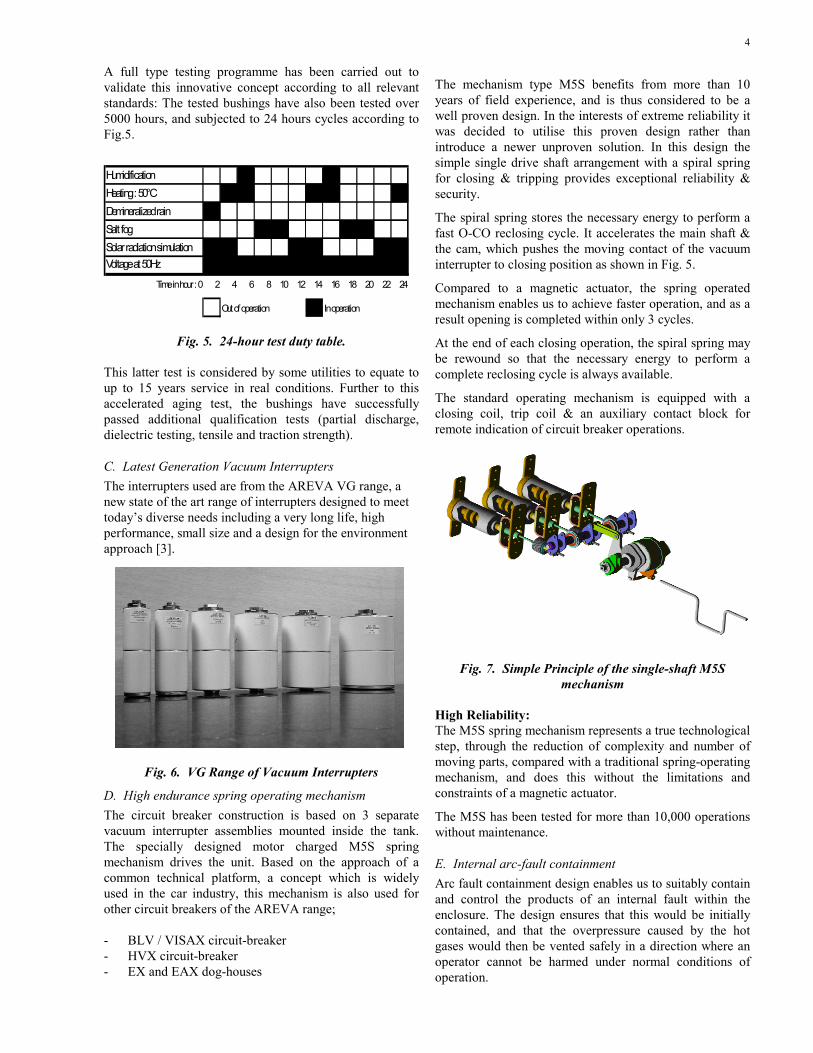
D. High endurance spring operating mechanism The circuit breaker construction is based on 3 separate vacuum interrupter assemblies mounted inside the tank. The specially designed motor charged M5S spring mechanism drives the unit. Based on the approach of a common technical platform, a concept which is widely used in the car industry, this mechanism is also used for other circuit breakers of the AREVA range; - BLV / VISAX circuit-breaker - HVX circuit-breaker - EX and EAX dog-houses
The mechanism type M5S benefits from more than 10 years of field experience, and is thus considered to be a well proven design. In the interests of extreme reliability it was decided to utilise this proven design rather than introduce a newer unproven solution. In this design the simple single drive shaft arrangement with a spiral spring for closing & tripping provides exceptional reliability & security.
The spiral spring stores the necessary energy to perform a fast O-CO reclosing cycle. It accelerates the main shaft & the cam, which pushes the moving contact of the vacuum interrupter to closing position as shown in Fig. 5.
Compared to a magnetic actuator, the spring operated mechanism enables us to achieve faster operation, and as a result opening is completed within only 3 cycles.
At the end of each closing operation, the spiral spring may be rewound so that the necessary energy to perform a complete reclosing cycle is always available.
The standard operating mechanism is equipped with a closing coil, trip coil & an auxiliary contact block for remote indication of circuit breaker operations.
Fig. 7. Simple Principle of the single-shaft M5S
mechanism High Reliability: The M5S spring mechanism represents a true technological step, through the reduction of complexity and number of moving parts, compared with a traditional spring-operating mechanism, and does this without the limitations and constraints of a magnetic actuator.
The M5S has been tested for more than 10,000 operations without maintenance.
E. Internal arc-fault containment Arc fault containment design enables us to suitably contain and control the products of an internal fault within the enclosure. The design ensures that this would be initially contained, and that the overpressure caused by the hot gases would then be vented safely in a direction where an operator cannot be harmed under normal conditions of operation.
HumidificationHeating : 50°CDemineralized rainSalt fogSolar radiation simulationVoltage at 50Hz
Time in hour : 0 2 4 6 8 10 12 14 16 18 20 22 24
Out of operation In operation

5
In the case of VOX, a pressure relief membrane calibrated to burst at 2.5 bars is welded to the tank, as shown in Fig. 6. The membrane is located in a duct, which is inside the LV cabinet, in order to benefit from the heating of the cabinet and its protection from external damage or pollution.
Upon operation of the membrane, the overpressure is be directed through a chimney, lifts up the roof of the control cabinet and the overpressure is then vented towards the sky, away from an operator or the public.
It is worth noting that the stainless steel bursting membrane is fully protected from water accumulation and pollution within its chimney, underneath the roof.
VOX has been subjected to internal arc fault containment according to IEC60298, Appendix AA, for both 25kA and 31.5kA short circuit currents.
Fig. 8(a). Membrane before test In order to cover the most stringent situation, an accessibility class A has been selected, with the cotton indicators located within 30 cm (9 inches) of the apparatus.
. With the same objective to cover all possible operational situations, tests have been repeated successfully with the control cabinet door in both the open and closed positions.
With the public liability of Utilities becoming a growing cost in insurance and legal fees, together with the possibility of managers being personally responsible in case of bodily injury, manufacturers are responding to this issue with safer equipment using the techniques described, and fully proven by type tests.
F. Short Line Fault Testing As VOX is designed to be connected directly to an overhead line, the short-line fault tests have been performed according to ANSI C37-09 (Test duties 8 and 9). This single-phase test made at 58% of the maximum rated voltage has demonstrated the short-line fault capability of the circuit breaker.
Test duty 8: Test duty 9: Voltage : 22 kV, rms Voltage 22kV, rms
Phase current : 19 kA, rms Phase current : 22.6 kA, rms Operating duty : O – O - O Operating duty : O – O – O
G. Seismic withstand testing VOX has been subjected to full size testing on a 3D shaking table in ISMES laboratories, Italy. Tests were carried out according to :IEC 61166, 1993, IEC 60068-2-6, 1995, IEC 60068-2-57, 1989, IEEE Std 693-1997
Parameters for the IEEE seismic test : • peak accelerations 0.5 g (X,Y) 0.4 g (Z) • frequency content 1÷37 Hz • time history duration 40.955 s • strong part of time history duration ≥ 20 s • sampling rate 200 Hz
Fig. 8(b). Membrane after test
It is worth mentioning that the all of the test sequences according to both the IEEE and the IEC standards have been performed on one single circuit breaker (Fig. 8). After the test no noteworthy problems were detected.
H. Dielectric Testing The dielectric withstand capability of VOX has been demonstrated by subjecting it to the following tests:
Power frequency; Wet tests : 75 kV, rms - 10 s Dry tests : 80 kV, rms - 1 min
Lightning impulse(bil); Full wave : 200 kV, peak
Chopped wave : 258 kV, peak

6
Fig. 8. VOX circuit breaker under test.
III. CONCLUSIONS
The paper describes a new innovative design of Dead Tank Medium Voltage circuit breaker which combines the known advantages of the Dead Tank concept with modern vacuum switching technology. This results in a concept which has been proven to give the best of both worlds, and which allows compliance with the latest standards and demands of the customer. We believe that this approach will give the Dead Tank concept in medium voltage a new lease of life for the 21st century.
IV. REFERENCES
Papers from Conference Proceedings (Published): [1] A, Beiri, X F Braud, and L. T. Falkingham “The Return of the
True Medium Voltage Dead Tank Circuit breaker” Proc. 2003 IEEE Power Engineering Society Transmission and Distribution Conf. Dallas.
[2] L. T. Falkingham “Fifty years of Vacuum Interrupter Development in the UK” Proc. of the XXth International Symposium on Discharges and Electrical Insulation in Vacuum, Tours, 2002.
[3] L. T. Falkingham and M Schlaug “The Next Generation of Vacuum Interrupters; Using a ″design for the environment″ Approach Proc. of CIRED, Barcelona, 2003
V. ACKNOWLEDGMENT
The authors gratefully acknowledge the contributions of the R&D teams in Montpellier and Manchester for their work in developing this product as well as those others within AREVA who were involved in the project.
VI. BIOGRAPHIES Leslie T Falkingham (SM’2003, M’1987) was born in Leeds, England, on May 13, 1955. He graduated from Lanchester Polytechnic, Coventry, England, in 1978 with BSc (Hons) in Combined Electrical and Mechanical Engineering, and has since studied part time at Cranfield University, receiving his PhD in Strategy & R&D Management in 2002.
Employment experience includes; Over ten years at VIL, London; two years with GEC South Africa where he designed and built a
new factory to manufacture vacuum interrupters; ten years with GEC Alsthom Rugby, where he built up and then led the ALSTOM Centre of Excellence for Vacuum Switching Technology. He has spent most of his working life involved in the design, development, and manufacture of vacuum interrupters for medium voltage switchgear, and holds a number of patents in this field. Since 2001 he has been Technology Director for AREVA T&D Medium Voltage Business, based in the T&D head office, Paris, France.
He is a Fellow of the Institution of Electrical Engineers and a Fellow of the Institution of Mechanical Engineers in the UK. He received the Nelson Gold Medal from GEC 1n 1997 for “Outstanding Technical Innovation”, and the J.J. Thomson Medal of the IEE in 2002 for his “Distinguished Contribution to Electronic Engineering”.
Siegfried A. Ruhland (M’2000) was born in Regensburg, Germany, on January 19, 1963. He received his diploma in electrical engineering from the Technical University Munich in 1988. His domain of work was high voltage engineering, especially digital data acquisition of very fast transients. Since 1988 he is working for AREVA Sachsenwerk in various positions. He received his doctoral degree in 1999 for his work related to electro-magnetic compatibility of gas insulated medium
voltage switchgear from the High Voltage Institute of the Technical University Munich. He is a member of several national and international committees, as well as a member of the German VDI and VDE. For the time being he is responsible for the primary distribution within AREVA T&D Medium Voltage Business.
Xavier-Franck Braud was born in France, on November 8, 1966. Mechanical Engineer from the National Institute of Applied Sciences, Lyon, he also has a Master in Business Administration from the University of Lyon. He has been working within the Transmission and Distribution division of ALSTOM since 1991, in the field of Medium Voltage. Further to postings in Australia and United Kingdom with responsibilities over technology
transfer and business development, Braud is currently Product Manager for the ALSTOM range of medium voltage switchgear for overhead distribution.