Embed Size (px)
Citation preview

Operation Manual, Part Number 07508000-006, Rev. A, May 17, 2013
Operation Manual
Series 8000 RF Signal Switch Solution

Series 8000
Operation Manual, Part Number 07508000-006, Rev. A, May 16, 2013 Page 2
All technical data and specifications in this publication are subject to change without prior notice and do not represent a commitment on the part of Giga-tronics, Incorporated.
© 2013 Giga-tronics Incorporated. All rights reserved. Printed in the U.S.A.
MODEL NUMBERS
The Series 8000 includes many models. Apart from the number of switches they support, the models are identical. The models are referred to in this manual by the general term Series 8000, except where it is necessary to make a distinction.
CONTACT INFORMATION
Giga-tronics, Incorporated
4650 Norris Canyon Road
San Ramon, California 94583
Telephone: 800.726.4442 (only within the United States)
+1 925.328.4650 (international)
Fax: 925.328.4700
Email: [email protected]
Website: www.gigatronics.com
Warranty
Giga-tronics Series 8000 instruments are warranted against defective
materials and workmanship for one year from date of shipment, or as
detailed in the warranty section of this manual. Giga-tronics will, at its
option, repair or replace products that are proven defective during the
warranty period. This warranty DOES NOT cover damage resulting from
improper use, nor workmanship other than Giga-tronics service. There is no
implied warranty of fitness for a particular purpose, nor is Giga-tronics liable
for any consequential damages. Specification and price change privileges are
reserved by Giga-tronics.

Series 8000
Operation Manual, Part Number 07508000-006, Rev. A, May 16, 2013 Page 3
Regulatory compliance information
This product complies with the essential requirements of the following applicable European Directives, and carries the CE mark accordingly.
89/336/EEC and 73/23/EEC EMC Directive and Low Voltage Directive
EN61010-1 (1993) Electrical Safety
EN61326-1 (1997) EMC – Emissions and Immunity
Manufacturer’s Name: Manufacturer’s Address
Giga-tronics, Incorporated 4650 Norris Canyon Road
San Ramon, California 94583
U.S.A.
Type of Equipment: Model Series Number
DC to 40 GHz RF Switch 8000
Model Numbers:
8000
Declaration of Conformity on file. Contact Giga-tronics at the following;
Giga-tronics, Incorporated
4650 Norris Canyon Road
San Ramon, California 94583
Telephone: 800.726.4442 (only within the United States)
925.328.4650
Fax: 925.328.4700

Series 8000
Operation Manual, Part Number 07508000-006, Rev. A, May 16, 2013 Page 4
Record of Changes to This Manual
Use the table below to maintain a permanent record of changes to this document. Corrected replacement pages are issued as Technical Publication Change Instructions (TCPI). When you are issued a TCPI, do the following:
1. Insert the TCPI at the front of the manual binder.
2. Remove the pages from the manual binder that are noted in the TCPI.
3. Replace the page(s) removed in the previous step with the corrected page(s).
4. Record the changes in the table below.
TPCI Number
TPCI Issue Date
Date Entered Comments

Series 8000
Operation Manual, Part Number 07508000-006, Rev. A, May 16, 2013 Page 5
Record of Changes Revision Description of Change Chg Order # Approved By
A Initial Release 3565 G.G.

Series 8000
Operation Manual, Part Number 07508000-006, Rev. A, May 16, 2013 Page 6
Table of Contents
SECTION 1 ..................................................................................................................................................... 7
SAFETY AND MANUAL CONVENTIONS ...................................................................................................... 7
OVERVIEW ................................................................................................................................................. 8
FUNCTIONAL DESCRIPTION ....................................................................................................................... 8
WARRANTY ............................................................................................................................................... 8
FRONT/REAR VIEW.................................................................................................................................... 9
SECTION 2 ................................................................................................................................................... 10
UNIT DEFAULTS ....................................................................................................................................... 10
CONTROL COMMANDS ........................................................................................................................... 10
SWITCH CLOSURE, COUNTER, QUERY COMMANDS ............................................................................... 11
SECTION 3 ................................................................................................................................................... 12
AC INPUT MODULE FUSE ........................................................................................................................ 12
52000100-024 - FUSE, 250V, TYPE T, SLO-BLO, 6.3 AMP .................................................................... 12
POWER SUPPLY SPECIFICATIONS ............................................................................................................ 12
47500680 – Universal Power Supply, 250W, 5V/30A & 12V/16.7A, W/FAN ..................................... 12
SECTION 4 ................................................................................................................................................... 13
RF SWITCH SPECIFICATIONS ................................................................................................................... 13
See your manual addendum for switch specifications. ...................................................................... 13
SECTION 5 ................................................................................................................................................... 14
OUTLINE DRAWINGS ............................................................................................................................... 14
Series 8000 OUTLINE DRAWING ......................................................................................................... 14
RF SWITCH FACE DETAIL ..................................................................................................................... 15

Series 8000 LAN
Operation Manual, Part Number 07508000-006, Rev. B, Nov. 15, 2010 Page 7
SECTION 1
SAFETY AND MANUAL CONVENTIONS
This manual contains conventions regarding safety and equipment usage as described below.
Product Reference
Throughout this manual, the term “Series 8000” refers to all models of within the series, unless otherwise specified.
Personal Safety Alert
WARNING: Indicates a hazardous situation which, if not avoided, could result in death or serious injury.
Equipment Safety Alert
CAUTION: Indicates a situation which can damage or adversely affect the product or associated equipment.
Notes
Notes are denoted and used as follows:
NOTE: Highlights or amplifies an essential operating or maintenance procedure, practice, condition or statement.
Electrical Safety Precautions
Any servicing instructions are for use by service-trained personnel only. To avoid personal injury, do not perform any service unless you are qualified to do so.
For continued protections against fire hazard, replace the AC line fuse only with a fuse of the same current rating and type. Do not use repaired fuses or short circuited fuse holders.
WARNING !
CAUTION

Series 8000
Operation Manual, Part Number 07508000-006, Rev. A, June 26, 2013 Page 8
OVERVIEW This manual describes a version of the Series 8000 products. They are full-rack wide units with
terminated RF Switches that are controlled by an Ethernet or GPIB Interface.
The Series 8000 line of switch products are based on rugged electromechanical switches and microwave
relays rated for use from DC to 40 GHz, with low insertion loss and high isolation. Route signals under
remote control to simplify and improve automated test systems. Easily removable switches allow
reduced mean time to repair.
The Series 8000 is a self-contained design, with built-in power supplies, microprocessor-based controller
board and up to 256 relay coils, making it easy to implement a microwave switch system. It is designed
to host many combinations of microwave relay switches, terminated or non-terminated: SPDT, SP4T,
SP6T, SP8T, or Transfer switches. With a standard SCPI command set, the control interface provides the
Series 8000 with ease of operation and configurability.
FUNCTIONAL DESCRIPTION The design is housed in a 3 RU (5.25 inch) high, full rack size unit. The unit fits in a standard 19 inch rack
cabinet and is provided with mounting flanges to enable it to be mounted in the rack.
The unit is self contained, that is, it contains its own power supplies, communications interface, RF relay
driver circuits and the RF relays mounted on the front. The RF Switches can be removed from the front
of the unit.
The Ethernet interface is an IEEE-488.2 device and uses standard Control commands to control its digital
interface. (See Section 2 for the Control Command Set for this instrument.)
A single power supply provides +5 VDC and +12 VDC to the unit. The power supply input is 90-250 VAC,
47-63 Hz. (See Section 3 for full specifications)
The RF switches are 50 Ohm impedance, with a frequency range capability of DC to 40 GHz. (See Section
4 for full specifications)
WARRANTY Product is warranted to conform to all applicable specifications for a period of one (1) year from
acceptance, or the relay cycle life, whichever comes first.

Series 8000
Operation Manual, Part Number 07508000-006, Rev. A, June 26, 2013 Page 9
FRONT/REAR VIEW
The figures below illustrate the front and rear power, power indicator and switch positions for the units.
Switch configuration and rear panel as shown are for reference only.
Figure 1 – Series 8000 Front panel view
Figure 2 – Series 8000 Rear panel view, LAN
Figure 3 – Series 8000 Rear panel view, GPIB

Series 8000
Operation Manual, Part Number 07508000-006, Rev. A, June 26, 2013 Page 10
SECTION 2
UNIT DEFAULTS
This unit is shipped from the factory with the following default settings:
Default IP Address (LAN units only): 192.168.5.254
Default Timeout: 1,000 seconds
Default GPIB Address(GPIB units only): 4
CONTROL COMMANDS
An example of control commands is shown below. For your specific configuration, reference the
addendum for your switch product.
LOCATION SW POSITIONS CONNECTS TO SCPI COMMANDS
S1 1 Open J3 (on Relay Control
board)
ROUTe:SWITch 1, 0
1 ROUTe:SWITch 1, 1
2 ROUTe:SWITch 1, 2
3 ROUTe:SWITch 1, 3
4 ROUTe:SWITch 1, 4
5 ROUTe:SWITch 1, 5
6 ROUTe:SWITch 1, 6
LOCATION SW POSITIONS CONNECTS TO SCPI COMMANDS
S6 6 Open J8 (on Relay Control
board)
ROUTe:SWITch 6, 0
1 ROUTe:SWITch 6, 1
2 ROUTe:SWITch 6, 2
3 ROUTe:SWITch 6, 3
4 ROUTe:SWITch 6, 4
5 ROUTe:SWITch 6, 5
6 ROUTe:SWITch 6, 6
NOTE: The commands referred to in this manual assume that the switches are connected properly to
the relay control board connectors. If the switches are physically moved to a different location in the
front panel, the command parameters DO NOT change. If such a physical change is made, the user
assumes the responsibility of properly identifying the switch locations.
Please consult Giga-tronics factory before making any changes in your equipment!
CAUTION
Series 8000
Operation Manual, Part Number 07508000-006, Rev. A, June 26, 2013 Page 11
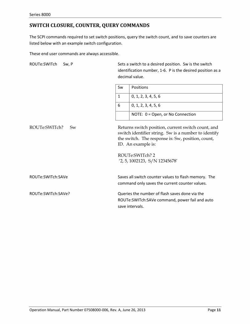
SWITCH CLOSURE, COUNTER, QUERY COMMANDS
The SCPI commands required to set switch positions, query the switch count, and to save counters are
listed below with an example switch configuration.
These end user commands are always accessible.
ROUTe:SWITch Sw, P Sets a switch to a desired position. Sw is the switch
identification number, 1-6. P is the desired position as a
decimal value.
Sw Positions
1 0, 1, 2, 3, 4, 5, 6
6 0, 1, 2, 3, 4, 5, 6
NOTE: 0 = Open, or No Connection
ROUTe:SWITch? Sw Returns switch position, current switch count, and switch identifier string. Sw is a number to identify the switch. The response is: Sw, position, count, ID. An example is:
ROUTe:SWITch? 2 ‘2, 5, 1002123, S/N 12345678’
ROUTe:SWITch:SAVe Saves all switch counter values to flash memory. The
command only saves the current counter values.
ROUTe:SWITch:SAVe? Queries the number of flash saves done via the
ROUTe:SWITch:SAVe command, power fail and auto
save intervals.

Series 8000
Operation Manual, Part Number 07508000-006, Rev. A, June 26, 2013 Page 12
SECTION 3
The unit is equipped with a replaceable fuse on the AC power input module
AC INPUT MODULE FUSE
52000100-024 - FUSE, 250V, TYPE T, SLO-BLO, 6.3 AMP
POWER SUPPLY SPECIFICATIONS
47500680 – Universal Power Supply, 250W, 5V/30A & 12V/16.7A, W/FAN
INPUT
Parameter Conditions /Description Min Nom Max Units
Input Frequency 47 63 Hz
Input Voltage 90 – 132 / 180 – 264 Auto-selectable 90 264 VAC
Input Current At 100 – 120 VAC At 200 – 240 VAC
8 4
A A
Inrush Current Peak measured at 230 VAC at full load, cold start Peak measured at 115 VAC at full load, cold start
35 70
A A
Power Factor Passive power factor correction meets EN61000-3-2 class A
OUTPUT
Parameter Conditions /Description Min Nom Max Units
Transient Response Output voltage returns to within 1 % in less than 2.5 ms for a 50 % load change. Peak transient does not exceed 5 %
2.5 ms
Overshoot Turn-on and turn-off overshoot shall not exceed 5% over nominal voltage
5 %
Efficiency Measured at 230 VAC and full load 75 %
Turn on Delay At 120 VAC 1 second
Hold up Time At 120 VAC and 80 % of rated maximum load 20 ms
PROTECTION CIRCUIT
Parameter Conditions /Description
Overload Current limiting starts at 110 – 140 % of the rated output current in foldback mode and recovers automatically
Short Circuit Short circuit can be continuous. Recovers automatically upon removal of shout
Output Over-voltage Output is protected against over-voltage. Unit shuts down and latches when the voltage at output terminals exceeds 130 %. AC needs to be reset to restart the power supply
Over Temperature Power Supply shuts down when temperature is in excess of 85°C. Auto Recovery

Series 8000
Operation Manual, Part Number 07508000-006, Rev. A, June 26, 2013 Page 13
SECTION 4
RF SWITCH SPECIFICATIONS
See your manual addendum for switch specifications.

Series 8000
Operation Manual, Part Number 07508000-006, Rev. A, June 26, 2013 Page 14
SECTION 5
OUTLINE DRAWINGS Series 8000 OUTLINE DRAWING
Note: Switch configuration as shown may different from your model

Series 8000
Operation Manual, Part Number 07508000-006, Rev. A, June 26, 2013 Page 15
RF SWITCH FACE DETAIL
2.25” x 2.25” SP6T switch shown is typical, for reference only.
All coax connector shall be tightened to the torque specified below.
Connector Type Material Torque Value
American Metric
SMA, SMA 2.9 Stainless Steel 7 – 10 in-lbs. 0.79 – 1.13 N-m

Series 8000
Operation Manual, Part Number 07508000-006, Rev. A, June 26, 2013 Page 16
Notes

Series 8000
Operation Manual, Part Number 07508000-006, Rev. A, June 26, 2013 Page 17