Embed Size (px)
Citation preview
SeriesSeries--Parallel CircuitsParallel Circuits
Topics Covered in Chapter 6
6-1: Finding RT for Series-Parallel Resistances
6-2: Resistance Strings in Parallel
6-3: Resistance Banks in Series
6-4: Resistance Banks and Strings in Series-Parallel
ChapterChapter
66
© 2007 The McGraw-Hill Companies, Inc. All rights reserved.
Topics Covered in Chapter 6Topics Covered in Chapter 6
6-5: Analyzing Series-Parallel Circuits with Random Unknowns
6-6: The Wheatstone Bridge
6-7: Troubleshooting: Opens and Shorts in Series-Parallel Circuits
McGraw-Hill © 2007 The McGraw-Hill Companies, Inc. All rights reserved.
66--1: Finding 1: Finding RRTTfor for
SeriesSeries--Parallel ResistancesParallel Resistances
Overview of Series-Parallel Circuits
A series-parallel circuit, or combination circuit,
combines both series and parallel connections.
Most electronic circuits fall into this category.
Series-parallel circuits are typically used when different
voltage and current values are required from the same
voltage source.
Series components form a series string.
Parallel components form a parallel bank.
66--1: Finding 1: Finding RRTTfor for
SeriesSeries--Parallel ResistancesParallel Resistances
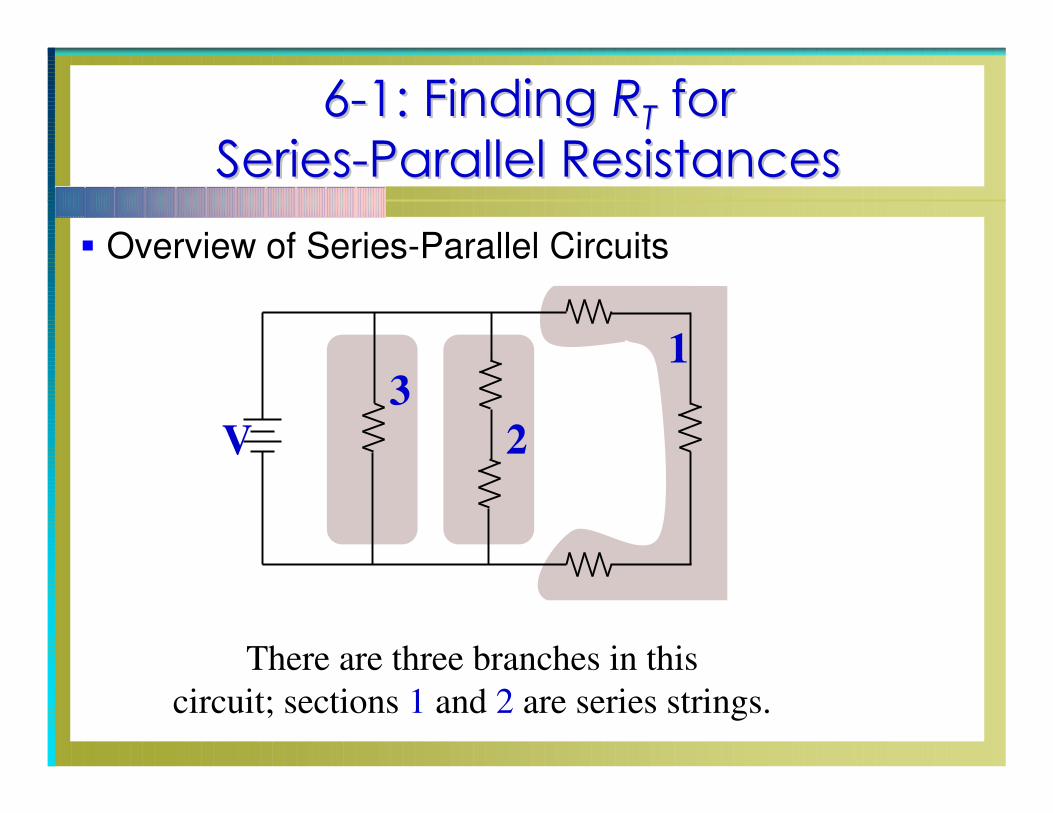
Overview of Series-Parallel Circuits
There are three branches in this
circuit; sections 1 and 2 are series strings.
1
2
3
V
66--1: Finding 1: Finding RRTTfor for
SeriesSeries--Parallel ResistancesParallel Resistances
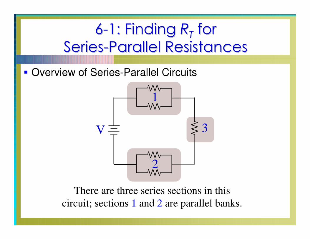
Overview of Series-Parallel Circuits
There are three series sections in this
circuit; sections 1 and 2 are parallel banks.
1
2
3V
66--1: Finding 1: Finding RRTTfor for
SeriesSeries--Parallel ResistancesParallel Resistances
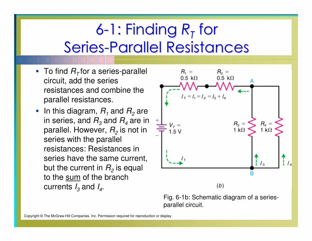
To find RT for a series-parallel circuit, add the series resistances and combine the parallel resistances.
In this diagram, R1 and R2 are in series, and R3 and R4 are in parallel. However, R2 is not in series with the parallel resistances: Resistances in series have the same current, but the current in R2 is equal to the sum of the branch currents I3 and I4.
Fig. 6-1b: Schematic diagram of a series-
parallel circuit.
Copyright © The McGraw-Hill Companies, Inc. Permission required for reproduction or display.
66--1: Finding 1: Finding RRTTfor for
SeriesSeries--Parallel ResistancesParallel Resistances
For Fig. 6-1b,
The series resistances are:
0.5kΩ + 0.5kΩ = 1kΩ
The parallel resistances are:
1kΩ / 2 = 0.5kΩ
The series and parallel values are then added for the
value of RT:
1kΩ + 0.5kΩ = 1.5 kΩ
66--2: Resistance Strings in Parallel2: Resistance Strings in Parallel
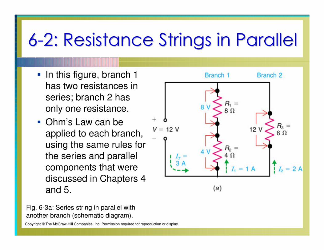
In this figure, branch 1 has two resistances in
series; branch 2 has only one resistance.
Ohm’s Law can be applied to each branch, using the same rules for the series and parallel
components that were discussed in Chapters 4 and 5.
Fig. 6-3a: Series string in parallel with
another branch (schematic diagram).Copyright © The McGraw-Hill Companies, Inc. Permission required for reproduction or display.
66--2: Resistance Strings in Parallel2: Resistance Strings in Parallel
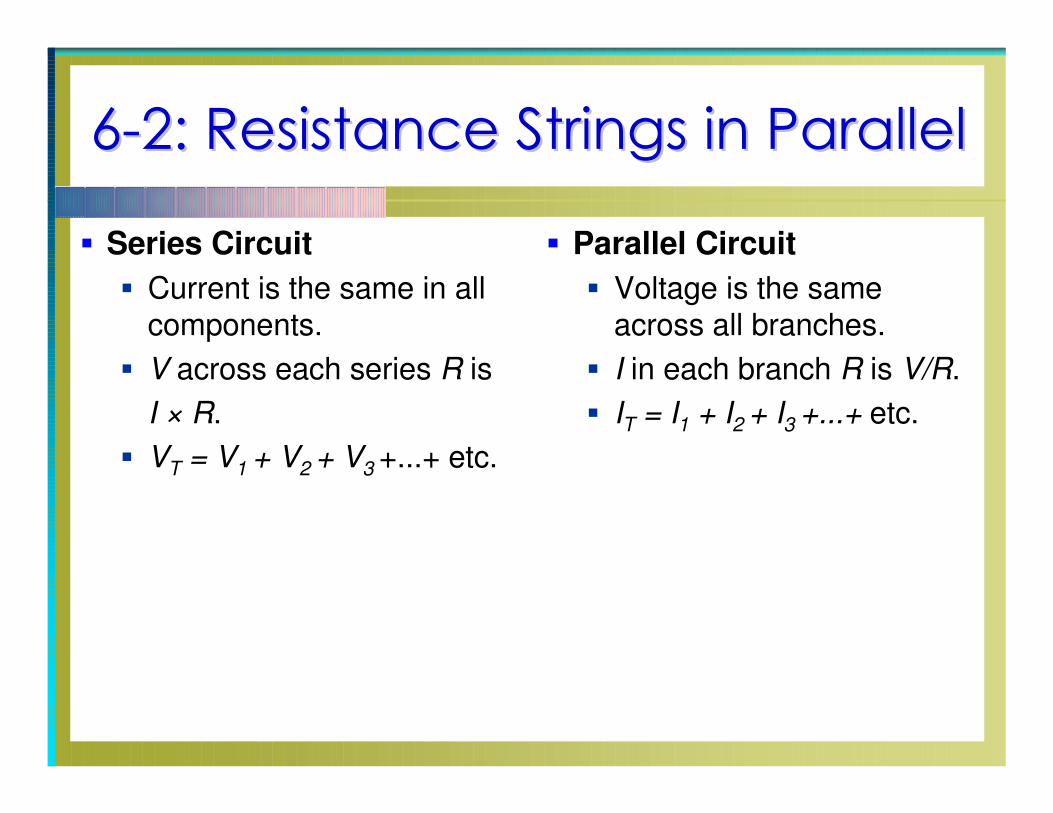
Series Circuit
Current is the same in all components.
V across each series R is
I × R.
VT = V1 + V2 + V3 +...+ etc.
Parallel Circuit
Voltage is the same across all branches.
I in each branch R is V/R.
IT = I1 + I2 + I3 +...+ etc.
66--2: Resistance Strings in Parallel2: Resistance Strings in Parallel
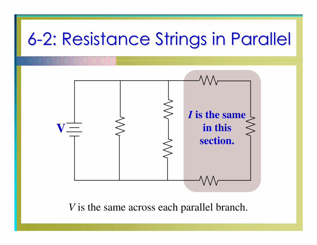
I is the same
in this
section.
V
V is the same across each parallel branch.
66--2: Resistance Strings in Parallel2: Resistance Strings in Parallel
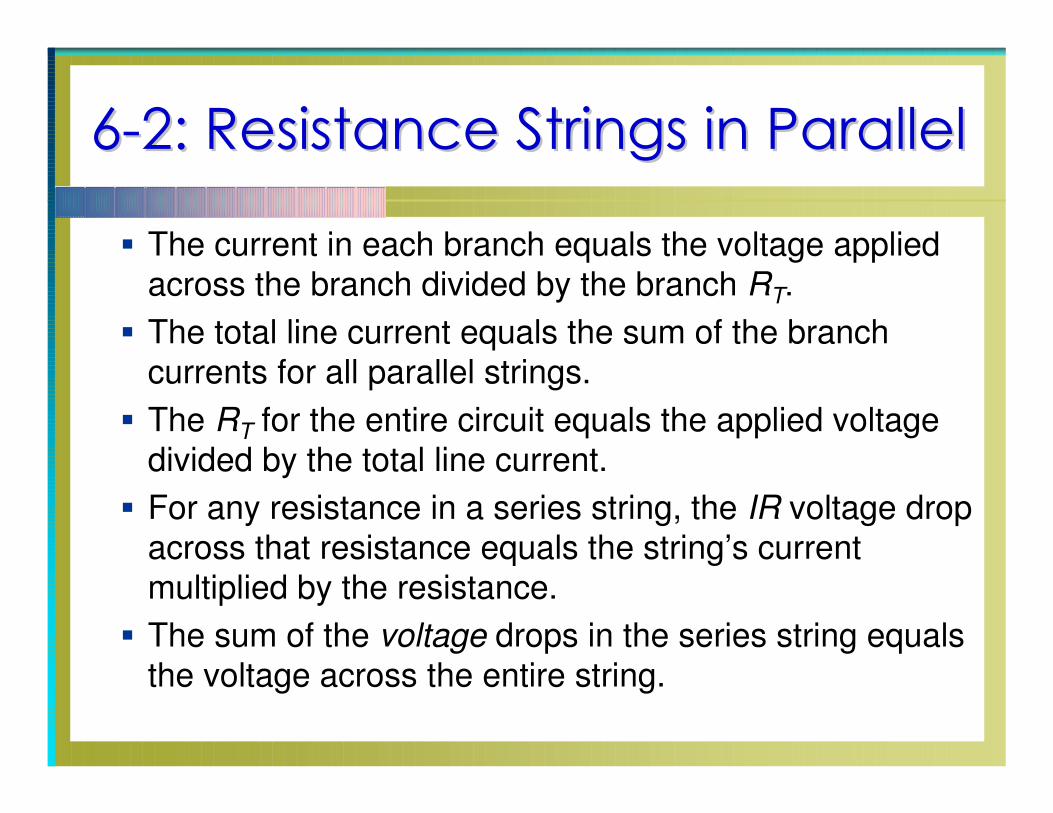
The current in each branch equals the voltage applied
across the branch divided by the branch RT.
The total line current equals the sum of the branch
currents for all parallel strings.
The RT for the entire circuit equals the applied voltage
divided by the total line current.
For any resistance in a series string, the IR voltage drop
across that resistance equals the string’s current
multiplied by the resistance.
The sum of the voltage drops in the series string equals
the voltage across the entire string.
66--3: Resistance Banks in Series3: Resistance Banks in Series
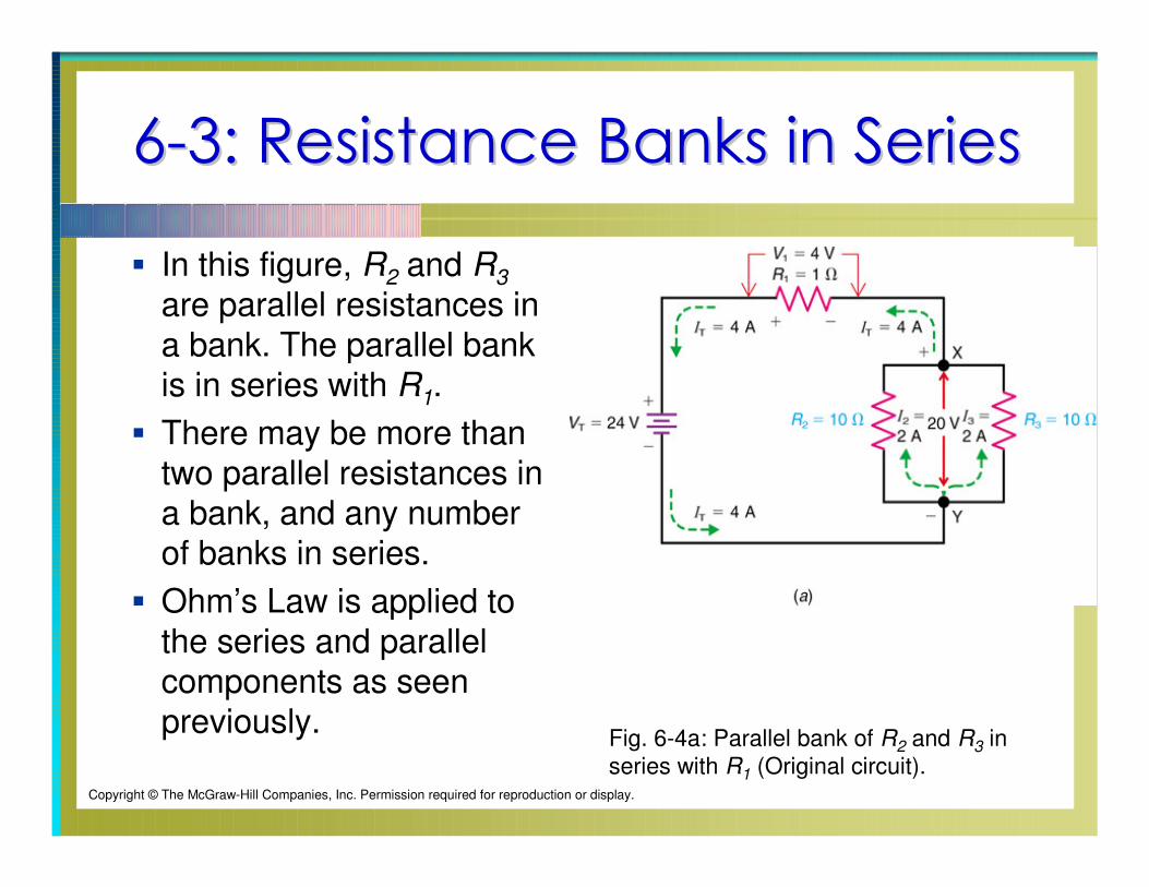
In this figure, R2 and R3
are parallel resistances in
a bank. The parallel bank is in series with R1.
There may be more than two parallel resistances in a bank, and any number of banks in series.
Ohm’s Law is applied to
the series and parallel components as seen previously.
Fig. 6-4a: Parallel bank of R2 and R3 in
series with R1 (Original circuit).Copyright © The McGraw-Hill Companies, Inc. Permission required for reproduction or display.
66--3: Resistance Banks in Series3: Resistance Banks in Series
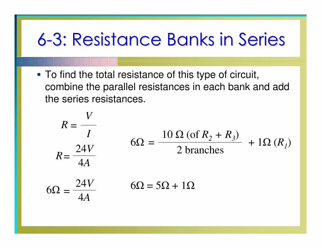
To find the total resistance of this type of circuit,
combine the parallel resistances in each bank and add
the series resistances.
V
IR =
6Ω =24V
4A
R=24V
4A
6Ω =10 Ω (of R
2+ R
3)
2 branches+ 1Ω (R
1)
6Ω = 5Ω + 1Ω
66--4: Resistance Banks and Strings in 4: Resistance Banks and Strings in
SeriesSeries--ParallelParallel
To solve series-parallel (combination) circuits, it is
important to know which components are in series with
one another and which components are in parallel.
Series components must be in one current path without
any branch points.
To find particular values for this type of circuit,
Reduce and combine the components using the rules
for individual series and parallel circuits.
Reduce the circuit to its simplest possible form.
Then solve for the needed values using Ohm’s Law.
66--4: Resistance Banks and Strings in 4: Resistance Banks and Strings in
SeriesSeries--ParallelParallel
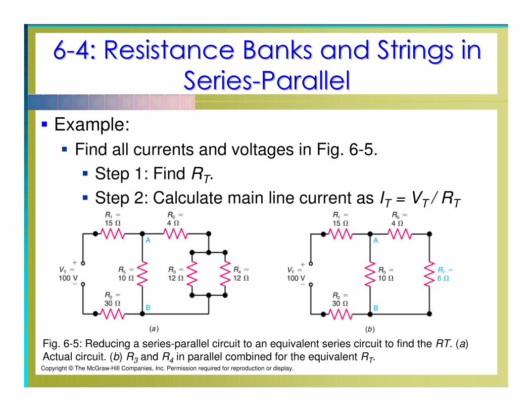
Example:
Find all currents and voltages in Fig. 6-5.
Step 1: Find RT.
Step 2: Calculate main line current as IT = VT / RT
Fig. 6-5: Reducing a series-parallel circuit to an equivalent series circuit to find the RT. (a)
Actual circuit. (b) R3 and R4 in parallel combined for the equivalent RT.Copyright © The McGraw-Hill Companies, Inc. Permission required for reproduction or display.
66--4: Resistance Banks and Strings in 4: Resistance Banks and Strings in
SeriesSeries--ParallelParallel
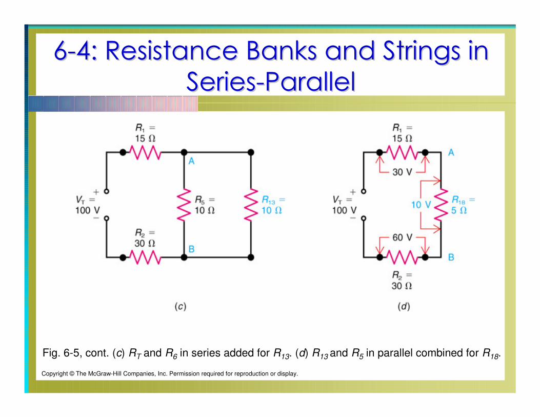
Fig. 6-5, cont. (c) RT and R6 in series added for R13. (d) R13 and R5 in parallel combined for R18.
Copyright © The McGraw-Hill Companies, Inc. Permission required for reproduction or display.
66--4: Resistance Banks and Strings in 4: Resistance Banks and Strings in
SeriesSeries--ParallelParallel
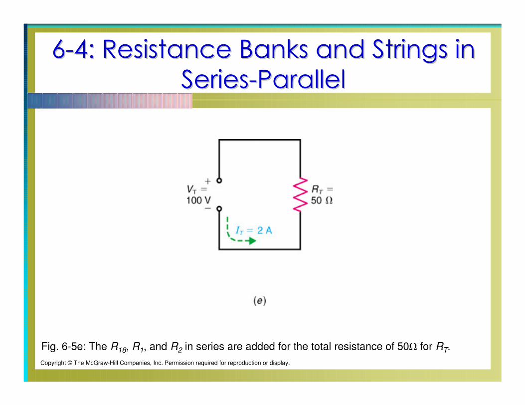
Fig. 6-5e: The R18, R1, and R2 in series are added for the total resistance of 50Ω for RT.
Copyright © The McGraw-Hill Companies, Inc. Permission required for reproduction or display.
66--5: Analyzing Series5: Analyzing Series--Parallel Circuits Parallel Circuits
with Random Unknownswith Random Unknowns
In solving such circuits, apply the same principles as
before:
Reduce the circuit to its simplest possible form.
Apply Ohm’s Law.
66--5: Analyzing Series5: Analyzing Series--Parallel Circuits Parallel Circuits
with Random Unknownswith Random Unknowns
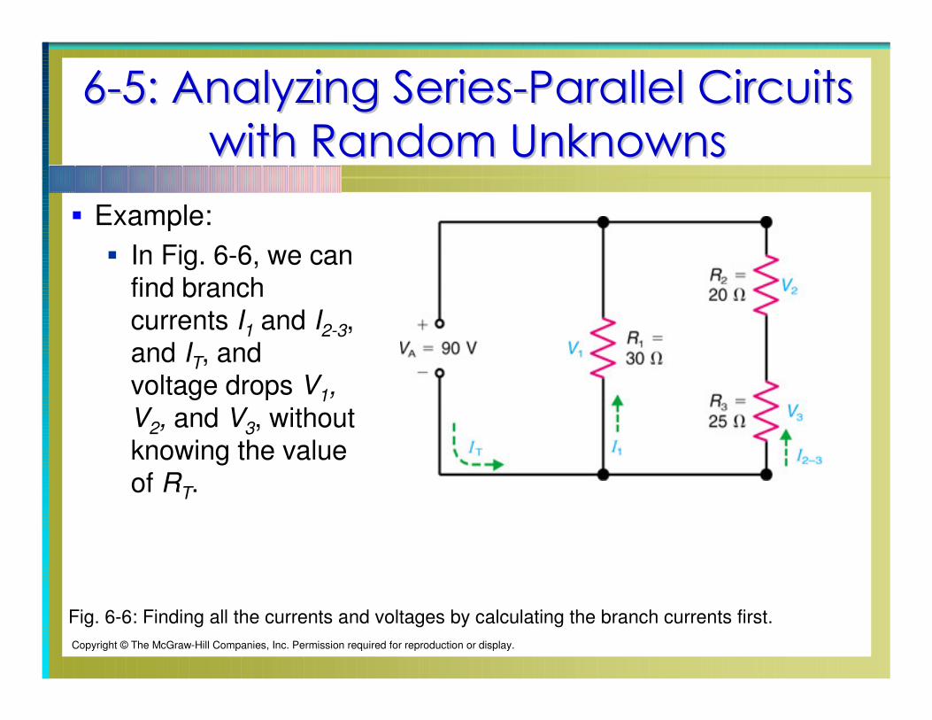
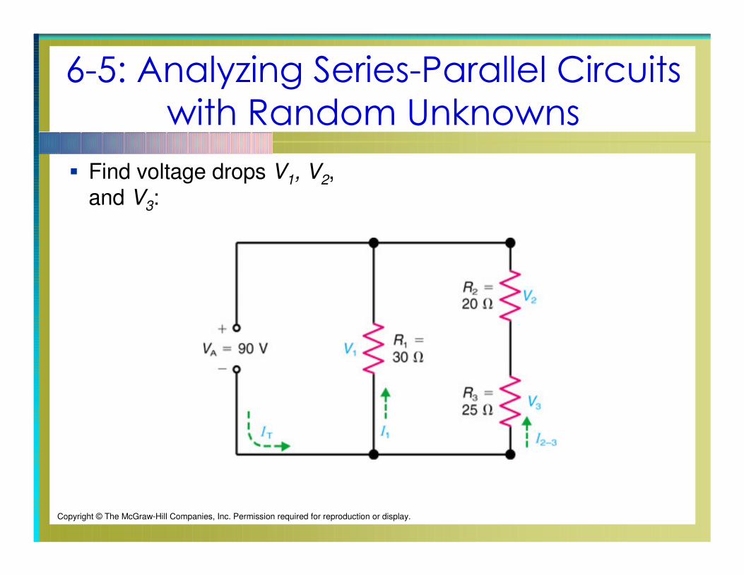
Example:
In Fig. 6-6, we can find branch currents I1 and I2-3, and IT, and voltage drops V1,
V2, and V3, without knowing the value of RT.
Fig. 6-6: Finding all the currents and voltages by calculating the branch currents first.
Copyright © The McGraw-Hill Companies, Inc. Permission required for reproduction or display.
66--5: Analyzing Series5: Analyzing Series--Parallel Circuits Parallel Circuits
with Random Unknownswith Random Unknowns
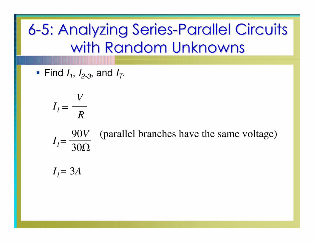
Find I1, I2-3, and IT.
V
RI1 =
I1= 3A
I1=
90V
30Ω
(parallel branches have the same voltage)
6-5: Analyzing Series-Parallel Circuits
with Random Unknowns
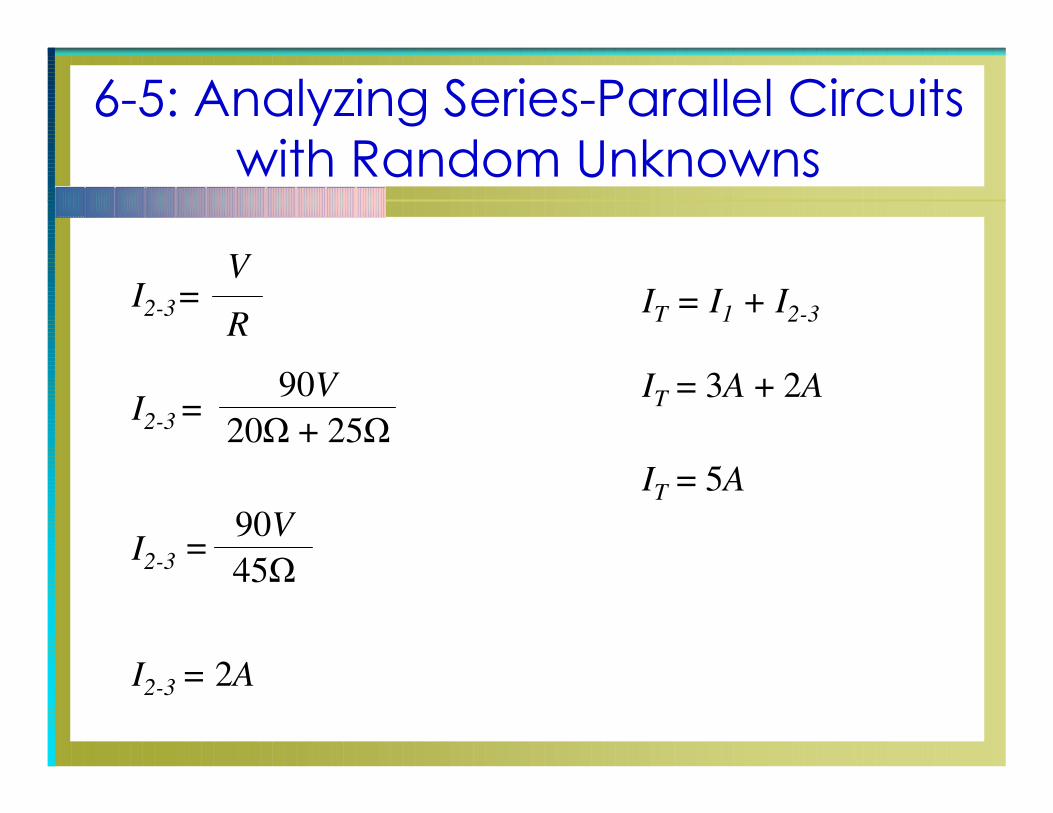
I2-3
=V
R
I2-3
= 2A
I2-3
=90V
20Ω + 25Ω
I2-3
=90V
45Ω
IT
= I1
+ I2-3
IT
= 3A + 2A
IT
= 5A
6-5: Analyzing Series-Parallel Circuits
with Random Unknowns
Find voltage drops V1, V2, and V3:
Copyright © The McGraw-Hill Companies, Inc. Permission required for reproduction or display.
6-5: Analyzing Series-Parallel Circuits
with Random Unknowns
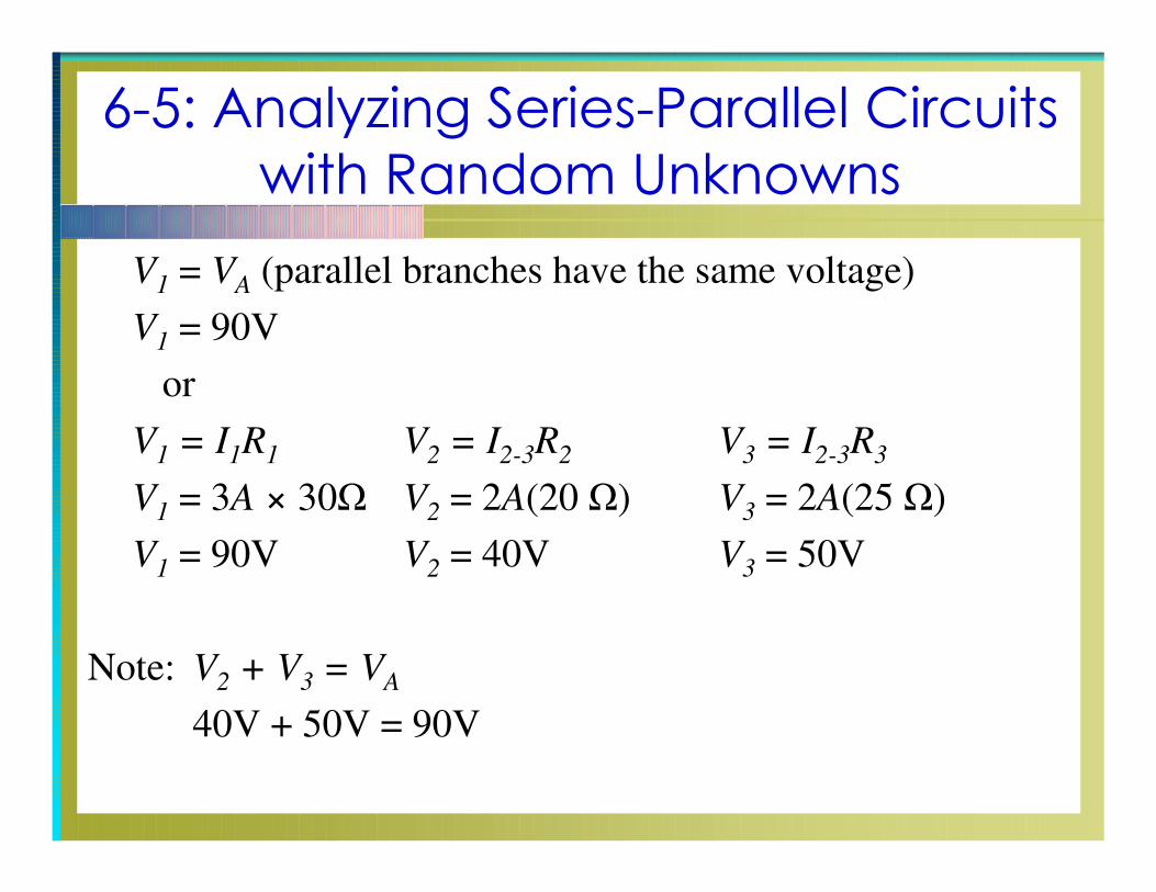
V1
= VA
(parallel branches have the same voltage)
V1
= 90V
or
V1
= I1R
1V
2= I
2-3R
2V
3= I
2-3R
3
V1
= 3A × 30Ω V2
= 2A(20 Ω) V3
= 2A(25 Ω)
V1
= 90V V2
= 40V V3
= 50V
Note: V2
+ V3
= VA
40V + 50V = 90V
6-5: Analyzing Series-Parallel Circuits
with Random Unknowns
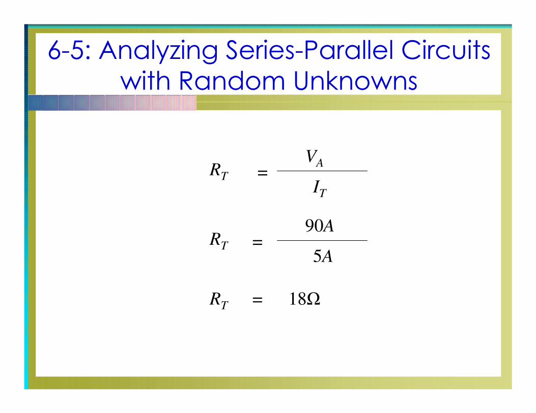
=RT
IT
VA
=RT
5A
90A
18Ω=RT
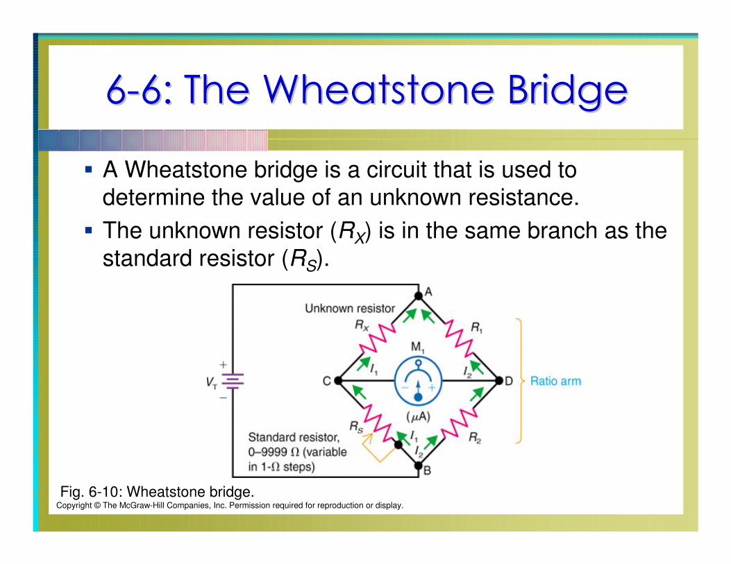
66--6: The Wheatstone Bridge6: The Wheatstone Bridge
A Wheatstone bridge is a circuit that is used to
determine the value of an unknown resistance.
The unknown resistor (RX) is in the same branch as the
standard resistor (RS).
Fig. 6-10: Wheatstone bridge.Copyright © The McGraw-Hill Companies, Inc. Permission required for reproduction or display.
66--6: The Wheatstone Bridge6: The Wheatstone Bridge
Resistors R1 and R2 form the ratio arm; they have very
tight resistance tolerances.
The galvanometer (M1), a sensitive current meter, is
connected between the output terminals C and D.
When R1 / R2 = R3 / R4, the bridge is balanced.
When the bridge is balanced, the current in M1 is zero.
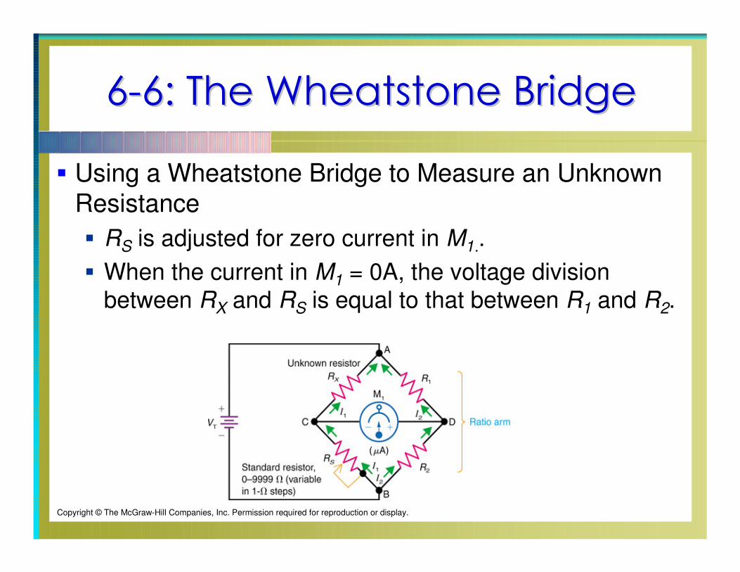
66--6: The Wheatstone Bridge6: The Wheatstone Bridge
Using a Wheatstone Bridge to Measure an Unknown Resistance
RS is adjusted for zero current in M1..
When the current in M1 = 0A, the voltage division
between RX and RS is equal to that between R1 and R2.
Copyright © The McGraw-Hill Companies, Inc. Permission required for reproduction or display.
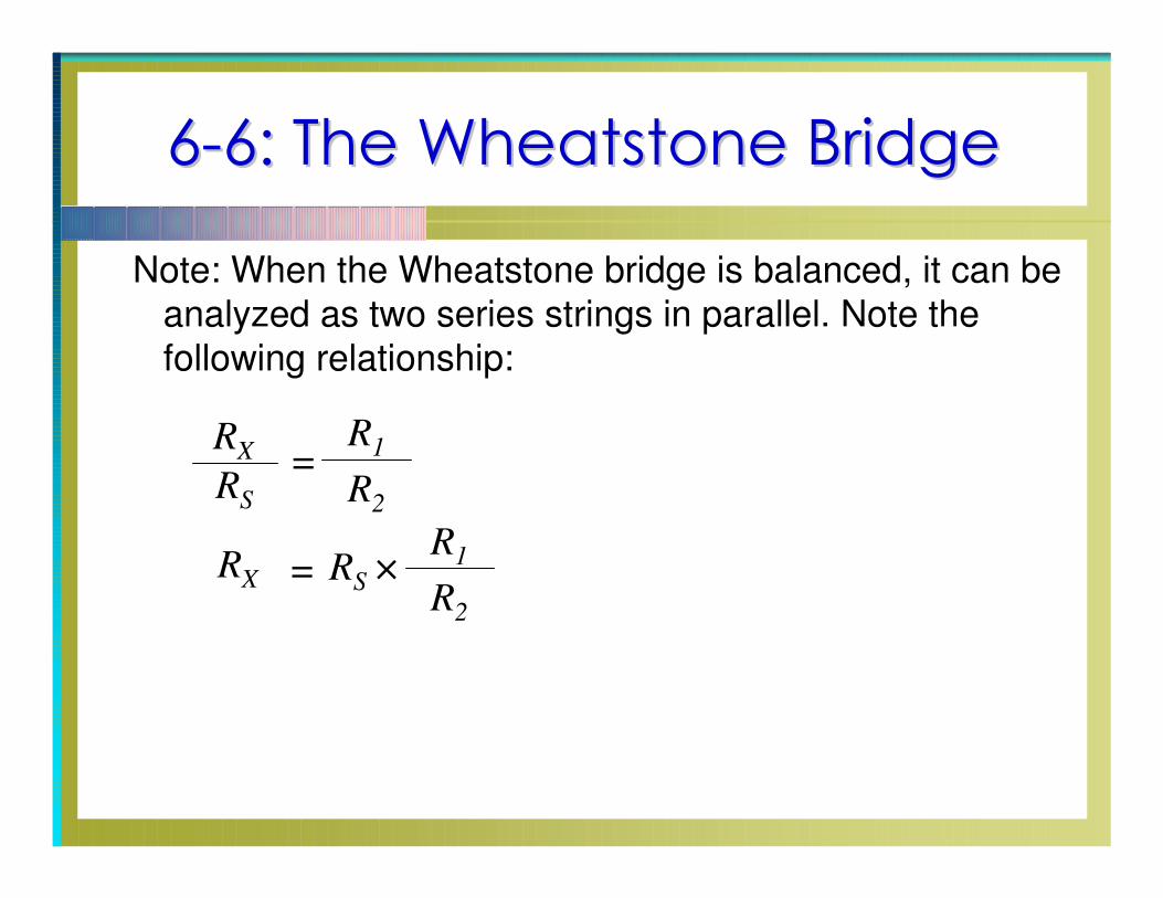
66--6: The Wheatstone Bridge6: The Wheatstone Bridge
Note: When the Wheatstone bridge is balanced, it can be
analyzed as two series strings in parallel. Note the
following relationship:
=R
S
RX
R1
R2
=RX R
S ×
R1
R2
66--7: Troubleshooting: Opens and 7: Troubleshooting: Opens and
Shorts in SeriesShorts in Series--Parallel CircuitsParallel Circuits
In series-parallel circuits, an open or short in one part of
the circuit changes the values in the entire circuit.
When troubleshooting series-parallel circuits, combine
the techniques used when troubleshooting individual
series and parallel circuits.
66--7: Troubleshooting: Opens and 7: Troubleshooting: Opens and
Shorts in SeriesShorts in Series--Parallel CircuitsParallel Circuits
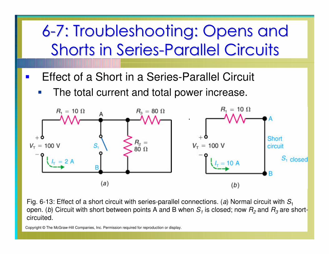
Effect of a Short in a Series-Parallel Circuit
The total current and total power increase.
Fig. 6-13: Effect of a short circuit with series-parallel connections. (a) Normal circuit with S1
open. (b) Circuit with short between points A and B when S1 is closed; now R2 and R3 are short-
circuited.
.
Copyright © The McGraw-Hill Companies, Inc. Permission required for reproduction or display.
66--7: Troubleshooting: Opens and 7: Troubleshooting: Opens and
Shorts in SeriesShorts in Series--Parallel CircuitsParallel Circuits
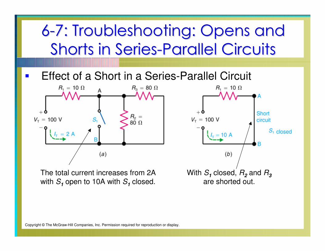
Effect of a Short in a Series-Parallel Circuit
Copyright © The McGraw-Hill Companies, Inc. Permission required for reproduction or display.
The total current increases from 2A
with S1
open to 10A with S1
closed.
With S1
closed, R2
and R3
are shorted out.
66--7: Troubleshooting: Opens and 7: Troubleshooting: Opens and
Shorts in SeriesShorts in Series--Parallel CircuitsParallel Circuits
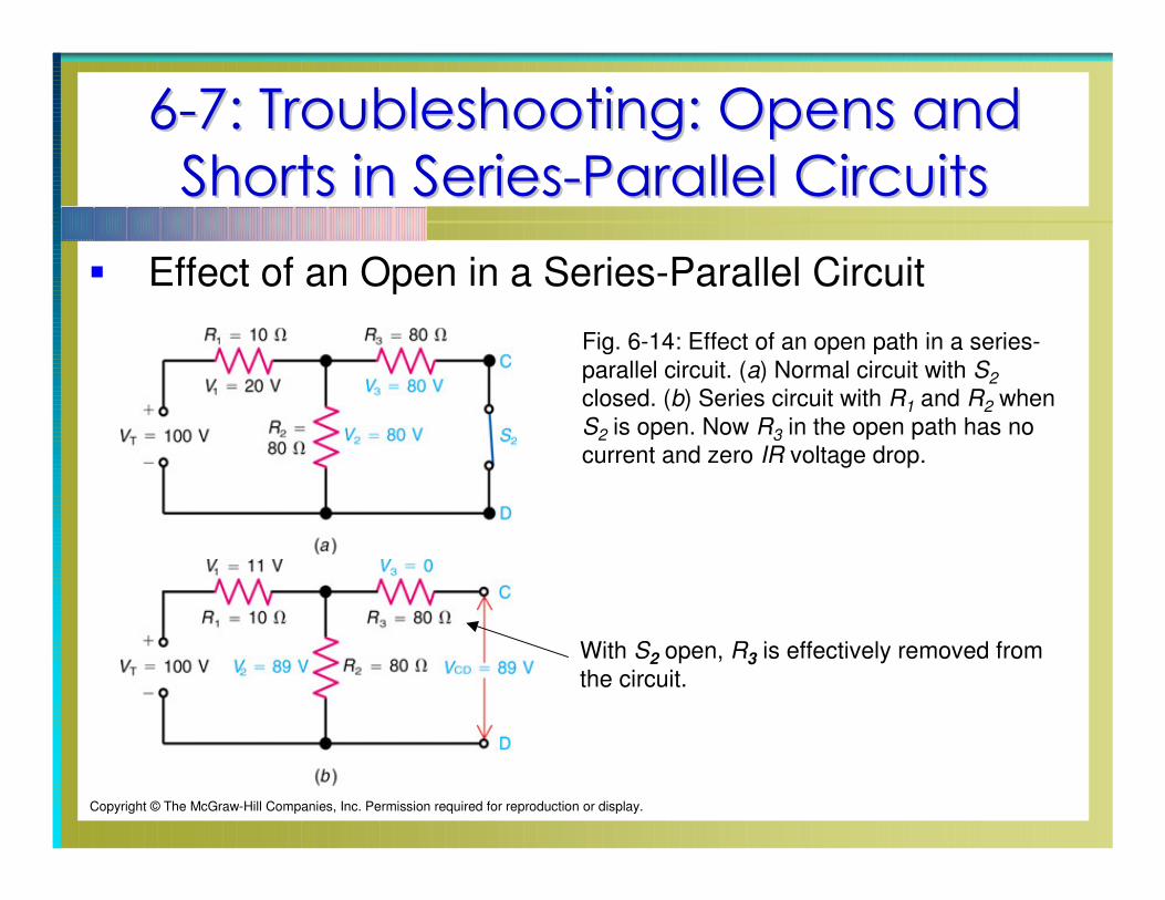
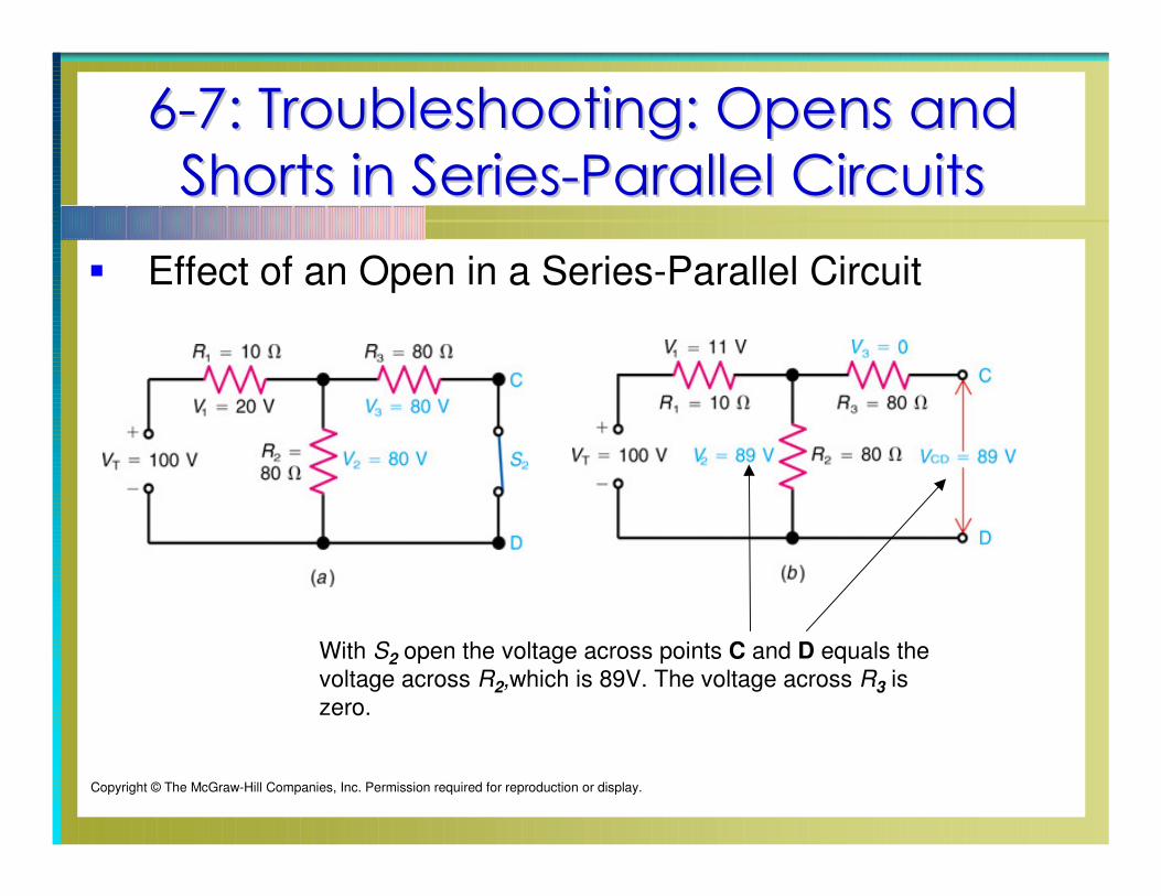
Effect of an Open in a Series-Parallel Circuit
Fig. 6-14: Effect of an open path in a series-
parallel circuit. (a) Normal circuit with S2
closed. (b) Series circuit with R1 and R2 when
S2 is open. Now R3 in the open path has no
current and zero IR voltage drop.
Copyright © The McGraw-Hill Companies, Inc. Permission required for reproduction or display.
With S2 open, R3 is effectively removed from
the circuit.
66--7: Troubleshooting: Opens and 7: Troubleshooting: Opens and
Shorts in SeriesShorts in Series--Parallel CircuitsParallel Circuits
Effect of an Open in a Series-Parallel Circuit
Copyright © The McGraw-Hill Companies, Inc. Permission required for reproduction or display.
With S2 open the voltage across points C and D equals the
voltage across R2,which is 89V. The voltage across R3 is
zero.