Embed Size (px)
Citation preview
1/16
SERVICE INSTRUCTIONS : HABEGGER GUIDE BUSH
WITH 3 POSITIONS
Table of contents
1 HABEGGER guide bush type TP with 3 positions ............................................................................ 3
1.1 General remarks ............................................................................................................................. 3
1.2 Function principle .......................................................................................................................... 3
2 Functions ................................................................................................................................................ 4
2.1 Action of the pneumatic pressure .............................................................................................. 4
2.2 Working position ............................................................................................................................. 4
2.3 Clamping position .......................................................................................................................... 4
2.4 Open position ................................................................................................................................. 4
3 Preparation of the machine .............................................................................................................. 5
3.1 Assembly of the guide bush ......................................................................................................... 5
3.2 Pneumatic connection of the guide bush ............................................................................... 5
3.3 Connection of the FESTO pneumatic box ................................................................................ 5
3.3.1 Pneumatic connection ........................................................................................................ 5
3.3.2 Electrical connection ........................................................................................................... 6
4 Adjustment of the guide bush ........................................................................................................... 6
4.1 Reception of the guide bush TP .................................................................................................. 6
4.2 Adjustment of the working position ............................................................................................ 6

2/16
4.3 Adjusting the clamping position ................................................................................................. 6
5 Application of the guide bush .......................................................................................................... 7
5.1 Guiding elements ........................................................................................................................... 7
5.2 Piloting the guide bush by CNC .................................................................................................. 7
5.2.1 Programming ......................................................................................................................... 7
5.2.2 Feeding cycle ........................................................................................................................ 7
5.2.3 Adaptation to the material bar tolerance ...................................................................... 7
5.2.4 Commutation between working position and clamping position .............................. 8
5.2.5 WARNING ................................................................................................................................ 8
6 Restriction of application ................................................................................................................... 8
6.1 Eventual reduction of the headstock spindle stroke .............................................................. 8
6.2 Information concerning the material geometry...................................................................... 8
6.3 Closing the guide bush only on a complete sector of raw material ................................... 9
6.4 Information for programming ...................................................................................................... 9
7 Lubrication of the guide bush ......................................................................................................... 10
7.1 Use of the filter .............................................................................................................................. 10
7.2 Spare part for the filter ................................................................................................................ 10
8 Mechanical intervention and setting ............................................................................................ 11
8.1 Exchange kit for the guide bush ............................................................................................... 11
8.2 Ordering spares ............................................................................................................................ 11
8.3 Replacing the exchange kit ...................................................................................................... 12
9 Assembly drawing .............................................................................................................................. 13
10 FESTO pneumatic box ................................................................................................................. 14
10.1 Pneumatic schema ................................................................................................................. 14
10.2 Electrical schema .................................................................................................................... 15
10.3 Pneumatic box spare parts list .............................................................................................. 16

3/16
1 HABEGGER guide bush type TP with 3 positions
1.1 General remarks
The guide bush with 3 positions, also called TP bush, is a fixed bush fitted with tungsten
carbide rollers in direct contact with the machined material bar. The adjustment is done by a pneumatic piston. Its principle is relatively simple: the usual guiding elements of HABEGGER bushes have not changed. The inside components are identical to those of our other bushes, with the exception of the rear nut. That nut, which is used for manual setting, has been replaced here by a pneumatic piston that permits to adjust the setting at any time.
The material bar gets guided by tungsten carbide rollers driven by the rotation of the bar itself. That is the function principle of a needle bearing, the inside cage of which would be
the bar (direct contact). Thus, the guiding of the material shows a very minimum of clearance.
1.2 Function principle
The TP bush aims to adapt itself to the tolerances of the material bars. It helps to increase the
rigidity of guiding in some particular machining operations. It helps to avoid the vibrations of the bar compared to conventional guide bushes, where a clearance between material bar and guide bush is needed for a good run.
The TP guide bush has three function positions i.e.:
- working position
- clamping position
- open position
The working and clamping positions are obtained by two different pressure levels. The first one corresponds to the guiding position (working). The second one corresponds to the closing position of the guide bush (clamping). A reversed pressure causes the forced opening of the guide bush.
The pneumatic device includes a box made by FESTO, which permits to control the two pressure levels. The pneumatic connection is done directly on the machine, with lubricated air, at a pressure of 5 – 6 bars.
Piloting the TP guide bush by the pneumatic box is obtained by two programmable outlets 24VDC available on the machine.
4/16
2 Functions
2.1 Action of the pneumatic pressure
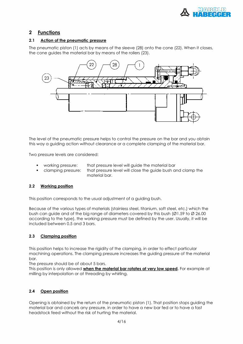
The pneumatic piston (1) acts by means of the sleeve (28) onto the cone (22). When it closes, the cone guides the material bar by means of the rollers (23).
The level of the pneumatic pressure helps to control the pressure on the bar and you obtain this way a guiding action without clearance or a complete clamping of the material bar.
Two pressure levels are considered:
� working pressure: that pressure level will guide the material bar � clamping pressure: that pressure level will close the guide bush and clamp the
material bar.
2.2 Working position
This position corresponds to the usual adjustment of a guiding bush. Because of the various types of materials (stainless steel, titanium, soft steel, etc.) which the bush can guide and of the big range of diameters covered by this bush (Ø1.59 to Ø 26.00 according to the type), the working pressure must be defined by the user. Usually, it will be
included between 0.5 and 3 bars.
2.3 Clamping position
This position helps to increase the rigidity of the clamping, in order to effect particular machining operations. The clamping pressure increases the guiding pressure of the material
bar. The pressure should be of about 5 bars. This position is only allowed when the material bar rotates at very low speed. For example at milling by interpolation or at threading by whirling.
2.4 Open position
Opening is obtained by the return of the pneumatic piston (1). That position stops guiding the material bar and cancels any pressure, in order to have a new bar fed or to have a fast headstock feed without the risk of hurting the material.
5/16
3 Preparation of the machine
3.1 Assembly of the guide bush
1. The guide bush TP can only be used with material bars, the nominal diameter of which corresponds to the size indicated on the lid (21). However, the construction of the bush permits to guide bars up to the tolerance h11.
2. To assemble the bush onto the machine, proceed as for a conventional bush, using
our bush holders. These give a perfect lubrication of the guide bush. 3. The guide bushes TP can be used on machines rotating to the right hand, CW, or to
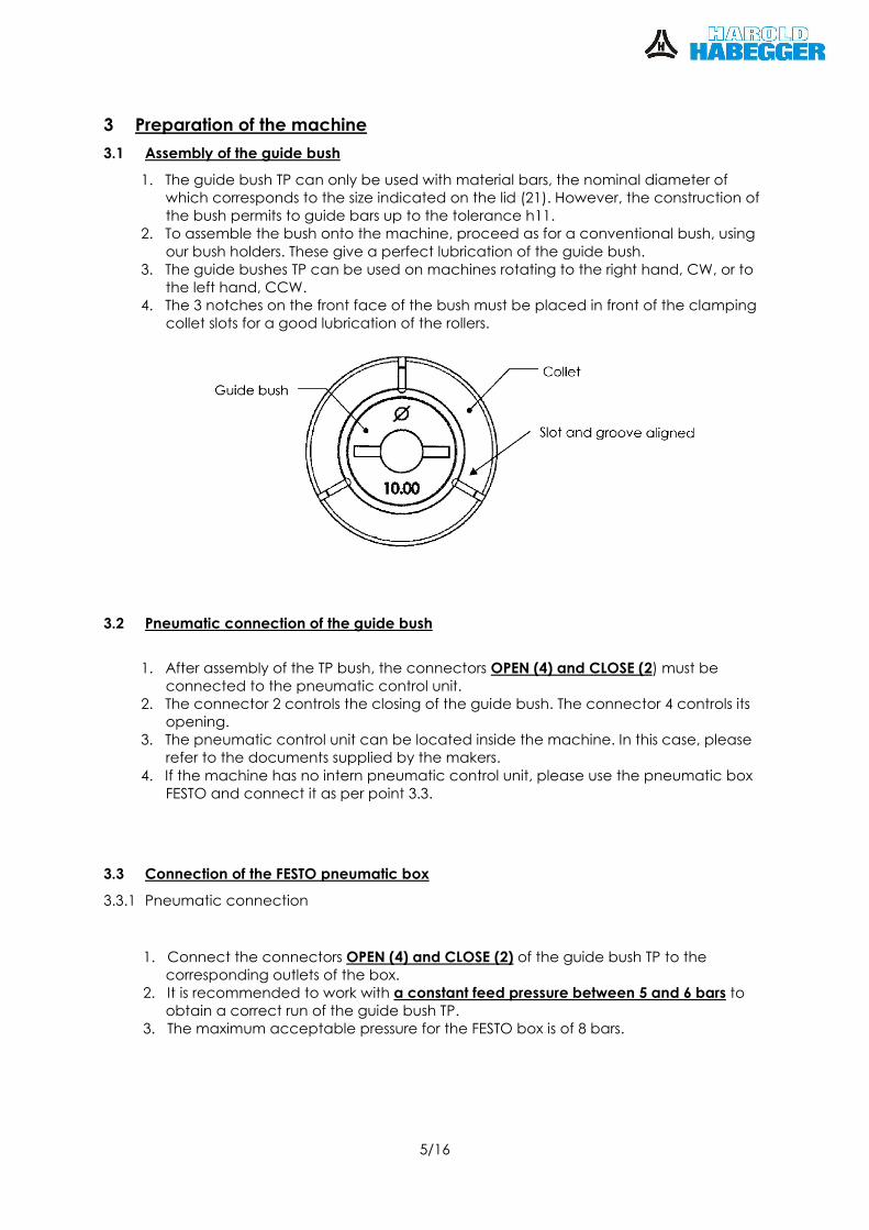
the left hand, CCW. 4. The 3 notches on the front face of the bush must be placed in front of the clamping
collet slots for a good lubrication of the rollers.
3.2 Pneumatic connection of the guide bush
1. After assembly of the TP bush, the connectors OPEN (4) and CLOSE (2) must be connected to the pneumatic control unit.
2. The connector 2 controls the closing of the guide bush. The connector 4 controls its opening.
3. The pneumatic control unit can be located inside the machine. In this case, please refer to the documents supplied by the makers.
4. If the machine has no intern pneumatic control unit, please use the pneumatic box FESTO and connect it as per point 3.3.
3.3 Connection of the FESTO pneumatic box
3.3.1 Pneumatic connection
1. Connect the connectors OPEN (4) and CLOSE (2) of the guide bush TP to the
corresponding outlets of the box. 2. It is recommended to work with a constant feed pressure between 5 and 6 bars to
obtain a correct run of the guide bush TP. 3. The maximum acceptable pressure for the FESTO box is of 8 bars.
6/16
3.3.2 Electrical connection
The valves Y1 (Wire No = 1) and Y2 (Wire No = 2) must be connected to the outlets of the control automate of the machine, as per electrical schema of chapter 10.2.
The electrical connection must be done as follows:
Wire No. Function
1 Opening/Closing of the bush by electro-valve Y1 (Y1 = 0: opening / Y1 = 1: closing)
2 Selection of working/clamping pressure by electro-valve Y2 (Y2 = 0: working/ Y2 = 1: clamping
3 Neutral (0V)
4 Protection (earth)
The control tension of the electro-valves must be 24 VDC/1.28W
4 Adjustment of the guide bush
4.1 Reception of the guide bush TP
At delivery, the guide bush has been pre-adjusted, no intervention is requested.
4.2 Adjustment of the working position
The guiding action of the material bar in the bush must be adjusted by adjustment of the working pressure level.
The final adjustment must always be done by increasing the pneumatic pressure. Check if the adjustment has been correctly done by effecting an opening/closing cycle. Avoid having the material bar polished by a bush that has been adjusted too tightly.
If the workpieces get too short, this means that the guiding pressure used for the bush is too high: the material slides in the clamping collet.
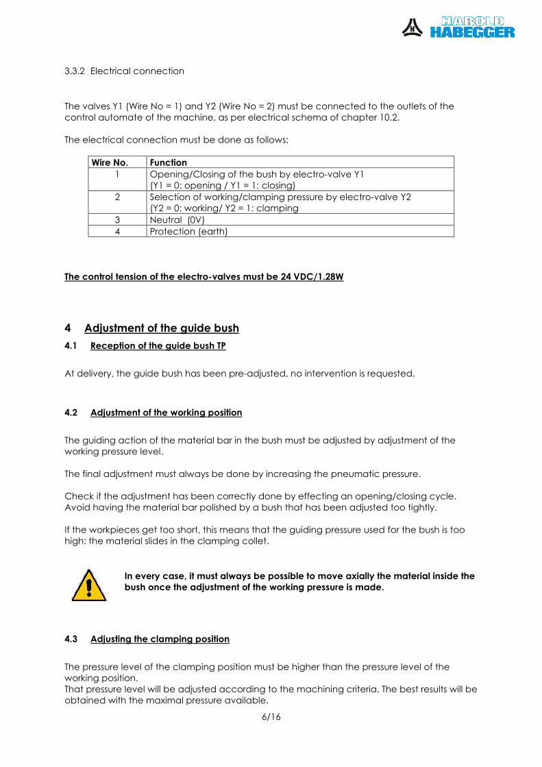
In every case, it must always be possible to move axially the material inside the bush once the adjustment of the working pressure is made.
4.3 Adjusting the clamping position
The pressure level of the clamping position must be higher than the pressure level of the working position. That pressure level will be adjusted according to the machining criteria. The best results will be obtained with the maximal pressure available.
7/16
5 Application of the guide bush
5.1 Guiding elements
The precision of the guide bush will be at its maximum after a few days use. The rollway of the rollers will become stable. It is recommended to change the radial position of the bush in the bush-holder from time to
time, in order to equilibrate the wear over the whole rollway of the rollers. Index therefore the guide bush by 120°.
5.2 Piloting the guide bush by CNC
5.2.1 Programming
Because of the diversity of the machines that can be fitted with the guide bush TP, a detailed
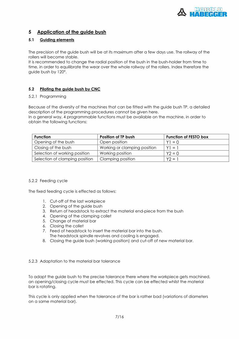
description of the programming procedures cannot be given here. In a general way, 4 programmable functions must be available on the machine, in order to obtain the following functions:
Function Position of TP bush Function of FESTO box Opening of the bush Open position Y1 = 0 Closing of the bush Working or clamping position Y1 = 1 Selection of working position Working position Y2 = 0 Selection of clamping position Clamping position Y2 = 1
5.2.2 Feeding cycle
The fixed feeding cycle is effected as follows:
1. Cut-off of the last workpiece 2. Opening of the guide bush 3. Return of headstock to extract the material end-piece from the bush 4. Opening of the clamping collet 5. Change of material bar
6. Closing the collet 7. Feed of headstock to insert the material bar into the bush.
The headstock spindle revolves and cooling is engaged. 8. Closing the guide bush (working position) and cut-off of new material bar.
5.2.3 Adaptation to the material bar tolerance
To adapt the guide bush to the precise tolerance there where the workpiece gets machined,
an opening/closing cycle must be effected. This cycle can be effected whilst the material bar is rotating. This cycle is only applied when the tolerance of the bar is rather bad (variations of diameters on a same material bar).
8/16
5.2.4 Commutation between working position and clamping position
The commutation from the clamping position to the working position must go through an open position of the guide bush. The commutation is effected as follows:
1) Clamping position → 2) Open position → 3) Working position
The commutation from the working position to the clamping position is direct, without going through an intermediate position. That is:
1) Working position → 2) clamping position
The clamping position is only activated when the spindle is stopped or only if the rotation speed of the spindle is lower than 50 rpm.
5.2.5 WARNING
In order to avoid a bar loading action whilst the guide bush is still closed, the connection as
per drawing FESTO box will cause that the guide bush is in open position if nothing else has been asked for.
When loading a new material bar, the closing of the guide bush must absolutely be programmed, in order to prevent machining operations whist the guide bush is still open. Mechanical harms may occur, mainly a tool breakage by vibrations, if that consign is not respected.
HAROLD HABEGGER SA declines any responsibility in such a case. When the material bar is rotating at a higher speed than 50 rpm, closing of the bush must be
asked for at the working pressure. At a higher speed, the clamping position is not allowed.
6 Restriction of application
6.1 Eventual reduction of the headstock spindle stroke
According to the machine configuration and to the type of guide bush TP, it may be that the pneumatic piston imposes a reduction of the headstock travel.
It is imperative to check that the limit position of the forward headstock travel has been configured, in order to prevent the risk of collision between the spindle nose and the back of the guide bush TP.
HAROLD HABEGGER SA declines any responsibility bound to a mechanical collision between the guide bush TP and the headstock.
6.2 Information concerning the material geometry
The TP bush adapts itself to dimensional variations of the machined material bar, but does not correct its geometry. For example: if the bar is oval or triangular, or if it shows some flats.
9/16
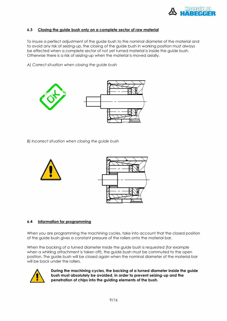
6.3 Closing the guide bush only on a complete sector of raw material
To insure a perfect adjustment of the guide bush to the nominal diameter of the material and to avoid any risk of seizing-up, the closing of the guide bush in working position must always be effected when a complete sector of not yet turned material is inside the guide bush. Otherwise there is a risk of seizing-up when the material is moved axially. A) Correct situation when closing the guide bush
B) Incorrect situation when closing the guide bush
6.4 Information for programming
When you are programming the machining cycles, take into account that the closed position of the guide bush gives a constant pressure of the rollers onto the material bar.
When the backing of a turned diameter inside the guide bush is requested (for example when a whirling attachment is taken off), the guide bush must be commuted to the open position. The guide bush will be closed again when the nominal diameter of the material bar will be back under the rollers.
During the machining cycles, the backing of a turned diameter inside the guide bush must absolutely be avoided, in order to prevent seizing-up and the penetration of chips into the guiding elements of the bush.
10/16
7 Lubrication of the guide bush
7.1 Use of the filter
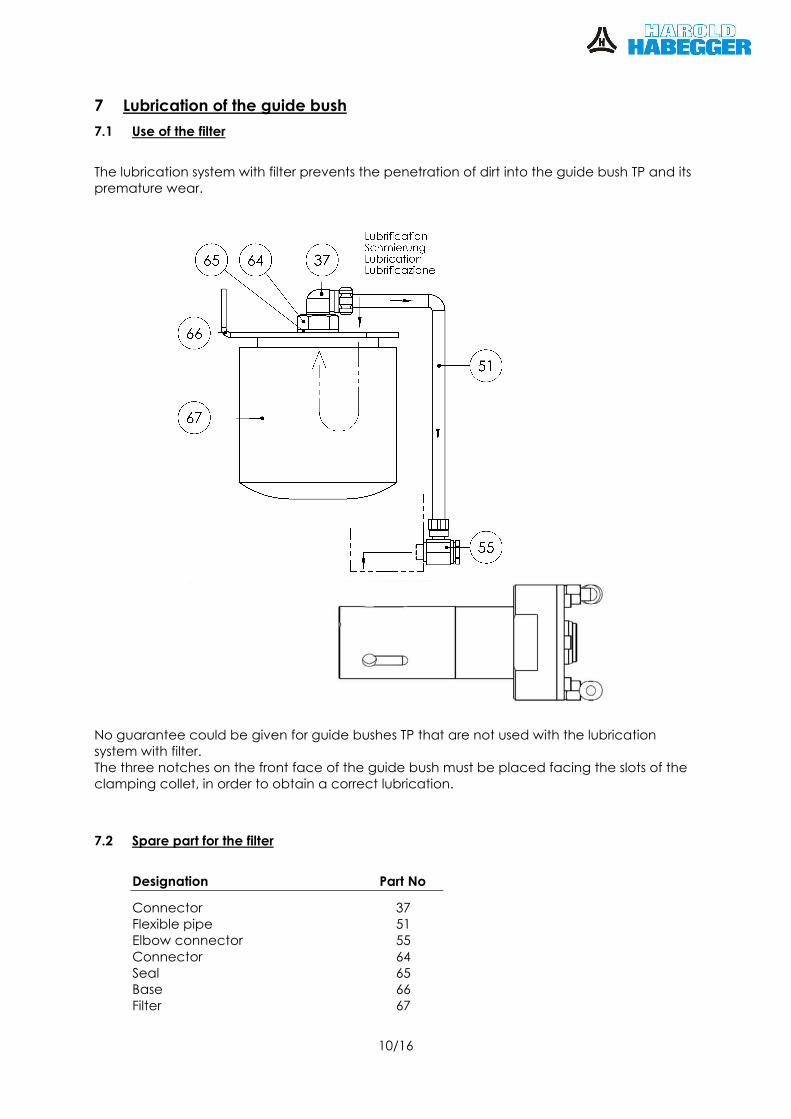
The lubrication system with filter prevents the penetration of dirt into the guide bush TP and its premature wear.
No guarantee could be given for guide bushes TP that are not used with the lubrication system with filter. The three notches on the front face of the guide bush must be placed facing the slots of the clamping collet, in order to obtain a correct lubrication.
7.2 Spare part for the filter
Designation Part No
Connector 37 Flexible pipe 51 Elbow connector 55
Connector 64 Seal 65 Base 66 Filter 67
11/16
8 Mechanical intervention and setting
A mechanical intervention on the guide bush is only requested when replacing the kit of spares.
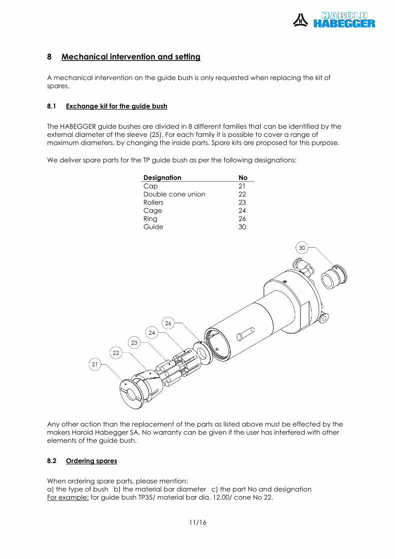
8.1 Exchange kit for the guide bush
The HABEGGER guide bushes are divided in 8 different families that can be identified by the external diameter of the sleeve (25). For each family it is possible to cover a range of maximum diameters, by changing the inside parts. Spare kits are proposed for this purpose.
We deliver spare parts for the TP guide bush as per the following designations:
Designation No Cap 21 Double cone union 22
Rollers 23 Cage 24 Ring 26 Guide 30
Any other action than the replacement of the parts as listed above must be effected by the makers Harold Habegger SA. No warranty can be given if the user has interfered with other elements of the guide bush.
8.2 Ordering spares
When ordering spare parts, please mention: a) the type of bush b) the material bar diameter c) the part No and designation For example: for guide bush TP35/ material bar dia. 12.00/ cone No 22.
12/16
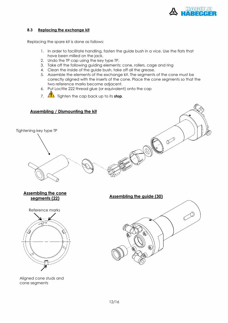
8.3 Replacing the exchange kit
Replacing the spare kit is done as follows:
1. In order to facilitate handling, fasten the guide bush in a vice. Use the flats that have been milled on the jack.
2. Undo the TP cap using the key type TP. 3. Take off the following guiding elements: cone, rollers, cage and ring
4. Clean the inside of the guide bush, take off all the grease. 5. Assemble the elements of the exchange kit. The segments of the cone must be
correctly aligned with the inserts of the cone. Place the cone segments so that the two reference marks become adjacent.
6. Put Loctite 222 thread glue (or equivalent) onto the cap
7. Tighten the cap back up to its stop.
Assembling / Dismounting the kit
Tightening key type TP
Reference marks repérage
Assembling the cone segments (22) Assembling the guide (30)
Aligned cone studs and cone segments
13/16
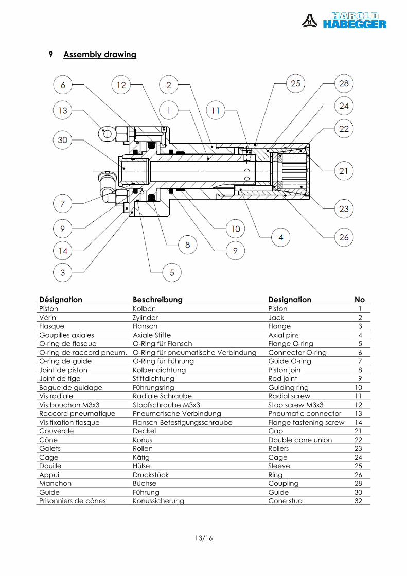
9 Assembly drawing
Désignation Beschreibung Designation No Piston Kolben Piston 1
Vérin Zylinder Jack 2
Flasque Flansch Flange 3
Goupilles axiales Axiale Stifte Axial pins 4
O-ring de flasque O-Ring für Flansch Flange O-ring 5
O-ring de raccord pneum. O-Ring für pneumatische Verbindung Connector O-ring 6
O-ring de guide O-Ring für Führung Guide O-ring 7
Joint de piston Kolbendichtung Piston joint 8
Joint de tige Stiftdichtung Rod joint 9
Bague de guidage Führungsring Guiding ring 10
Vis radiale Radiale Schraube Radial screw 11
Vis bouchon M3x3 Stopfschraube M3x3 Stop screw M3x3 12
Raccord pneumatique Pneumatische Verbindung Pneumatic connector 13
Vis fixation flasque Flansch-Befestigungsschraube Flange fastening screw 14
Couvercle Deckel Cap 21
Cône Konus Double cone union 22
Galets Rollen Rollers 23
Cage Käfig Cage 24
Douille Hülse Sleeve 25
Appui Druckstück Ring 26
Manchon Büchse Coupling 28
Guide Führung Guide 30
Prisonniers de cônes Konussicherung Cone stud 32
14/16
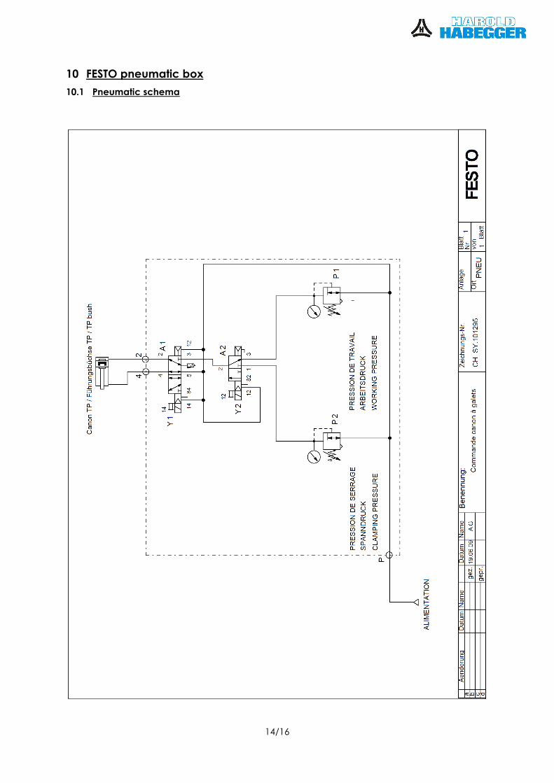
10 FESTO pneumatic box
10.1 Pneumatic schema
15/16
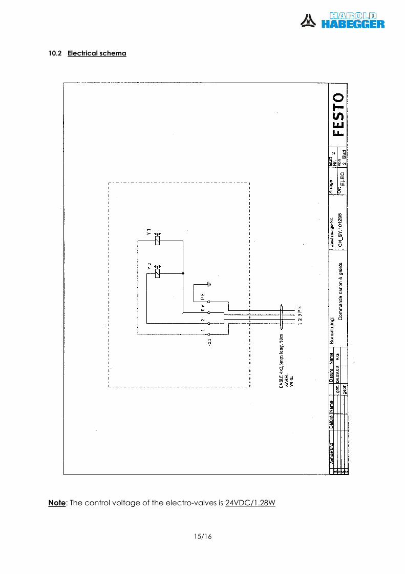
10.2 Electrical schema
Note: The control voltage of the electro-valves is 24VDC/1.28W

16/16
10.3 Pneumatic box spare parts list
Pos Part number Quantity Type Description A1 196928 1 CPE10-M1BH-5LS-M7 Solenoid valve
193687 1 KMYZ-9-24-2,5-LED-PUR-B Plug socket with cable
186352 2 QSML-M7-4 Push-in L-fitting
186353 1 QSML-M7-6 Push-in L-fitting
161418 2 UC-M7 Silencer
153332 2 QSML-M3-4 Push-in L-fitting
A2 196916 1 CPE10-M1BH-3GLS-M7 Solenoid valve
193687 1 KMYZ-9-24-2,5-LED-PUR-B Plug socket with cable
186353 3 QSML-M7-6 Push-in L-fitting
153332 1 QSML-M3-4 Push-in L-fitting
P1 192299 1 LR-1/8-D-7-I-MINI Pressure regulator
153046 3 QSL-1/8-6 Push-in L-fitting
159596 1 FMA-40-10-1/4-EN Flanged pressure gauge
153275 1 QSLF-1/4-6-B Push-in L-fitting
P2 192299 1 LR-1/8-D-7-I-MINI Pressure regulator
153046 2 QSL-1/8-6 Push-in L-fitting
153107 1 QST-1/8-6 Push-in T-fitting
159596 1 FMA-40-10-1/4-EN Flanged pressure gauge
153275 1 QSLF-1/4-6-B Push-in L-fitting
Accessories
1 EB 1549.600 Box RITTAL 200x200x120mm
153164 1 QSSF-1/4-6-B Push-in bulkhead fitting
153157 2 QSS-4 Push-in bulkhead connector
153371 2 QSMY-4 Push-in Y-connector
153369 1 QSMT-6-4 Push-in T connector
153304 2 QSM-M5-4 Push-in fitting
12010071 4 Terminal block 4mm2
12010076 2 End stop
11911300 10m Wire 4mm2
Harold Habegger SA CH-2738 Court www.habegger-sa.com February 27, 2017 Alterations reserved