Embed Size (px)
Citation preview
3B
BRAVO ONE GEAR HOUSINGSERVICE MANUAL NUMBER 11
90-17431--4 MARCH 1998 Page 3B-1
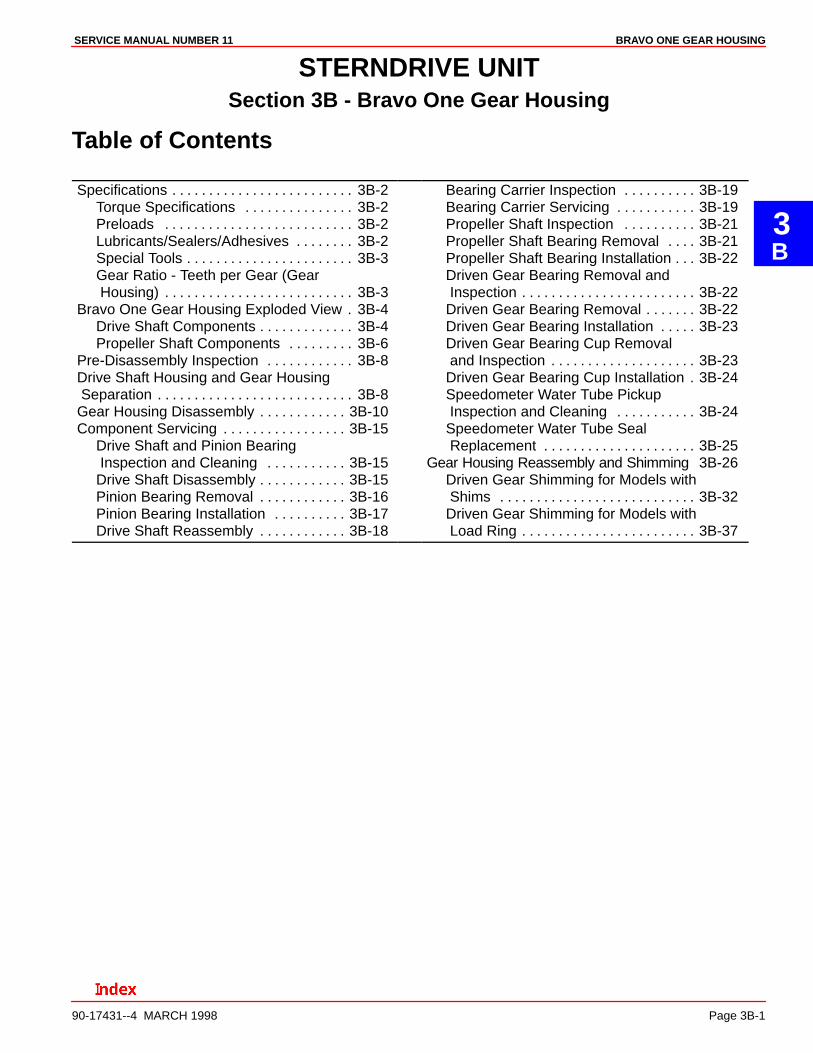
STERNDRIVE UNITSection 3B - Bravo One Gear Housing
Table of Contents
Specifications 3B-2. . . . . . . . . . . . . . . . . . . . . . . . . Torque Specifications 3B-2. . . . . . . . . . . . . . . Preloads 3B-2. . . . . . . . . . . . . . . . . . . . . . . . . . Lubricants/Sealers/Adhesives 3B-2. . . . . . . . Special Tools 3B-3. . . . . . . . . . . . . . . . . . . . . . . Gear Ratio - Teeth per Gear (Gear Housing) 3B-3. . . . . . . . . . . . . . . . . . . . . . . . . .
Bravo One Gear Housing Exploded View 3B-4. Drive Shaft Components 3B-4. . . . . . . . . . . . . Propeller Shaft Components 3B-6. . . . . . . . .
Pre-Disassembly Inspection 3B-8. . . . . . . . . . . . Drive Shaft Housing and Gear Housing Separation 3B-8. . . . . . . . . . . . . . . . . . . . . . . . . . . Gear Housing Disassembly 3B-10. . . . . . . . . . . . Component Servicing 3B-15. . . . . . . . . . . . . . . . .
Drive Shaft and Pinion Bearing Inspection and Cleaning 3B-15. . . . . . . . . . . Drive Shaft Disassembly 3B-15. . . . . . . . . . . . Pinion Bearing Removal 3B-16. . . . . . . . . . . . Pinion Bearing Installation 3B-17. . . . . . . . . . Drive Shaft Reassembly 3B-18. . . . . . . . . . . .
Bearing Carrier Inspection 3B-19. . . . . . . . . . Bearing Carrier Servicing 3B-19. . . . . . . . . . . Propeller Shaft Inspection 3B-21. . . . . . . . . . Propeller Shaft Bearing Removal 3B-21. . . . Propeller Shaft Bearing Installation 3B-22. . . Driven Gear Bearing Removal and Inspection 3B-22. . . . . . . . . . . . . . . . . . . . . . . . Driven Gear Bearing Removal 3B-22. . . . . . . Driven Gear Bearing Installation 3B-23. . . . . Driven Gear Bearing Cup Removal and Inspection 3B-23. . . . . . . . . . . . . . . . . . . . Driven Gear Bearing Cup Installation 3B-24. Speedometer Water Tube Pickup Inspection and Cleaning 3B-24. . . . . . . . . . . Speedometer Water Tube Seal Replacement 3B-25. . . . . . . . . . . . . . . . . . . . .
Gear Housing Reassembly and Shimming 3B-26Driven Gear Shimming for Models with Shims 3B-32. . . . . . . . . . . . . . . . . . . . . . . . . . . Driven Gear Shimming for Models with Load Ring 3B-37. . . . . . . . . . . . . . . . . . . . . . . .
BRAVO ONE GEAR HOUSING SERVICE MANUAL NUMBER 11
Page 3B-2 90-17431--4 MARCH 1998
Specifications
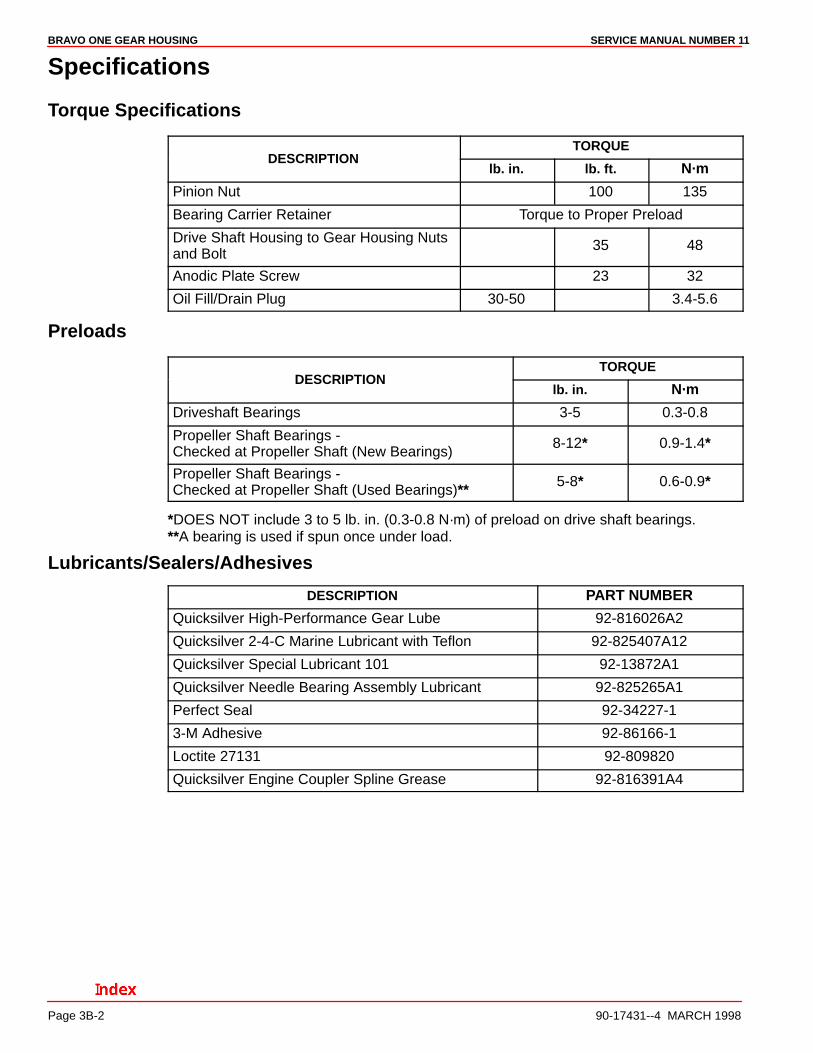
Torque Specifications
TORQUEDESCRIPTION
lb. in. lb. ft. N·m
Pinion Nut 100 135
Bearing Carrier Retainer Torque to Proper Preload
Drive Shaft Housing to Gear Housing Nutsand Bolt
35 48
Anodic Plate Screw 23 32
Oil Fill/Drain Plug 30-50 3.4-5.6
Preloads
TORQUEDESCRIPTION
lb. in. N·m
Driveshaft Bearings 3-5 0.3-0.8
Propeller Shaft Bearings -Checked at Propeller Shaft (New Bearings)
8-12* 0.9-1.4*
Propeller Shaft Bearings -Checked at Propeller Shaft (Used Bearings)** 5-8* 0.6-0.9*
*DOES NOT include 3 to 5 lb. in. (0.3-0.8 N·m) of preload on drive shaft bearings.**A bearing is used if spun once under load.
Lubricants/Sealers/Adhesives
DESCRIPTION PART NUMBER
Quicksilver High-Performance Gear Lube 92-816026A2
Quicksilver 2-4-C Marine Lubricant with Teflon 92-825407A12
Quicksilver Special Lubricant 101 92-13872A1
Quicksilver Needle Bearing Assembly Lubricant 92-825265A1
Perfect Seal 92-34227-1
3-M Adhesive 92-86166-1
Loctite 27131 92-809820
Quicksilver Engine Coupler Spline Grease 92-816391A4
BRAVO ONE GEAR HOUSINGSERVICE MANUAL NUMBER 11
90-17431--4 MARCH 1998 Page 3B-3
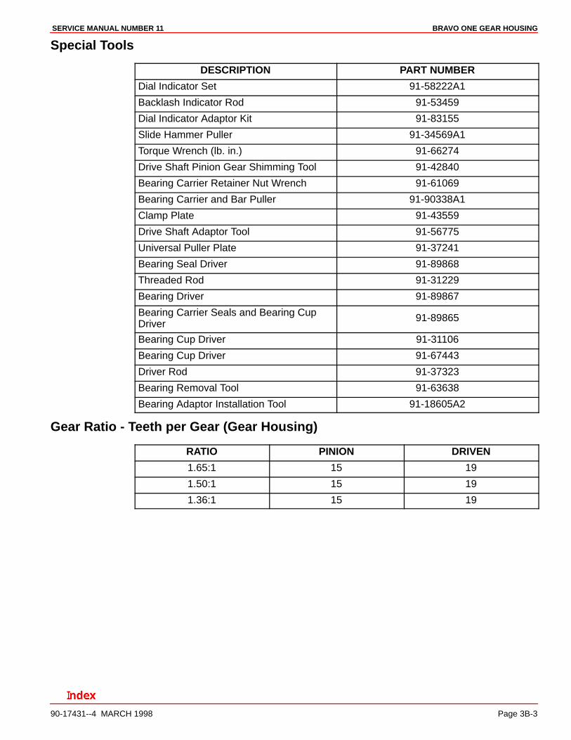
Special Tools
DESCRIPTION PART NUMBER
Dial Indicator Set 91-58222A1
Backlash Indicator Rod 91-53459
Dial Indicator Adaptor Kit 91-83155
Slide Hammer Puller 91-34569A1
Torque Wrench (lb. in.) 91-66274
Drive Shaft Pinion Gear Shimming Tool 91-42840
Bearing Carrier Retainer Nut Wrench 91-61069
Bearing Carrier and Bar Puller 91-90338A1
Clamp Plate 91-43559
Drive Shaft Adaptor Tool 91-56775
Universal Puller Plate 91-37241
Bearing Seal Driver 91-89868
Threaded Rod 91-31229
Bearing Driver 91-89867
Bearing Carrier Seals and Bearing CupDriver
91-89865
Bearing Cup Driver 91-31106
Bearing Cup Driver 91-67443
Driver Rod 91-37323
Bearing Removal Tool 91-63638
Bearing Adaptor Installation Tool 91-18605A2
Gear Ratio - Teeth per Gear (Gear Housing)
RATIO PINION DRIVEN
1.65:1 15 19
1.50:1 15 19
1.36:1 15 19
BRAVO ONE GEAR HOUSING SERVICE MANUAL NUMBER 11
Page 3B-4 90-17431--4 MARCH 1998
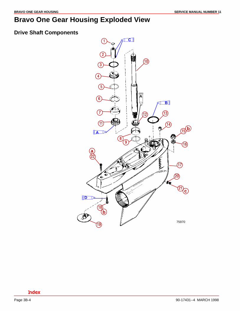
Bravo One Gear Housing Exploded View
Drive Shaft Components
75970
��
��
��
��
��
�
�
�
�
�
�
��
��
�� ��
�
�
A
A
C
�
D
��
��
B
a
b
c
b
BRAVO ONE GEAR HOUSINGSERVICE MANUAL NUMBER 11
90-17431--4 MARCH 1998 Page 3B-5
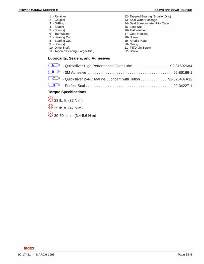
1 - Retainer2 - Coupler3 - O-Ring4 - Spacer5 - Shim(s)6 - Tab Washer7 - Bearing Cup8 - Bearing Cup9 - Shim(s)10- Drive Shaft11- Tapered Bearing (Larger Dia.)
12- Tapered Bearing (Smaller Dia.)13- Seal Water Passage14- Seal Speedometer Pitot Tube15- Lock Nut16- Flat Washer17- Gear Housing18- Screw19- Anodic Plate20- O-ring21- Fill/Drain Screw22- Screw
Lubricants, Sealers, and Adhesives
A - Quicksilver High Performance Gear Lube 92-816026A4. . . . . . . . . . . . . . . . . . .
B - 3M Adhesive 92-86166-1. . . . . . . . . . . . . . . . . . . . . . . . . . . . . . . . . . . . . . . . . . . . . .
C - Quicksilver 2-4-C Marine Lubricant with Teflon 92-825407A12. . . . . . . . . . . . . .
D - Perfect Seal 92-34227-1. . . . . . . . . . . . . . . . . . . . . . . . . . . . . . . . . . . . . . . . . . . . . . .
Torque Specifications
a 23 lb. ft. (32 N·m)
b 35 lb. ft. (47 N·m)
c 30-50 lb. in. (3.4-5.6 N·m)
BRAVO ONE GEAR HOUSING SERVICE MANUAL NUMBER 11
Page 3B-6 90-17431--4 MARCH 1998
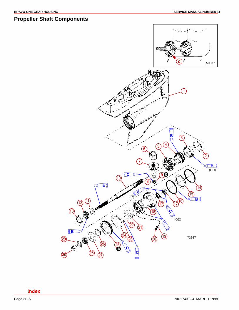
Propeller Shaft Components
73367
�
�
�
�
��
��
�
���
��
��
���
��
� ���
��
��
��
����
��
�
a
b
B
B
(OD)
B
C
C
(OD)
A(ID)
DC
B
E
F
��
����
�
�
50337cc
BRAVO ONE GEAR HOUSINGSERVICE MANUAL NUMBER 11
90-17431--4 MARCH 1998 Page 3B-7
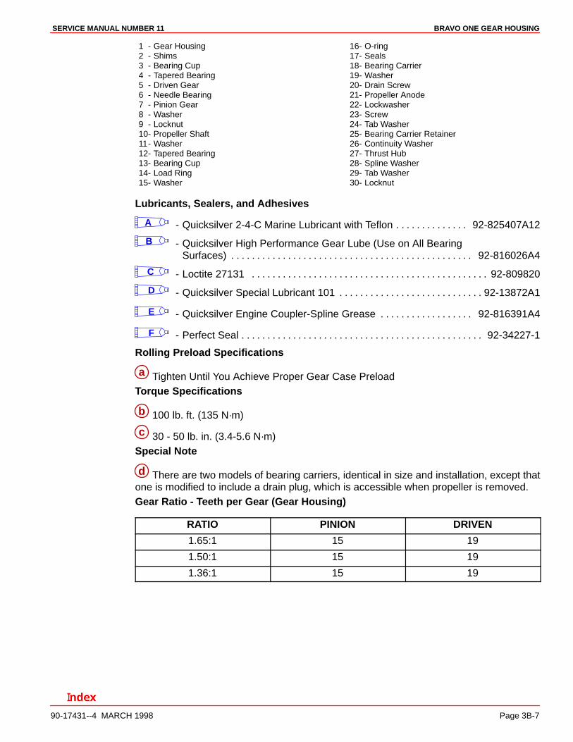
1 - Gear Housing2 - Shims3 - Bearing Cup4 - Tapered Bearing5 - Driven Gear6 - Needle Bearing7 - Pinion Gear8 - Washer9 - Locknut10- Propeller Shaft11- Washer12- Tapered Bearing13- Bearing Cup14- Load Ring15- Washer
16- O-ring17- Seals18- Bearing Carrier19- Washer20- Drain Screw21- Propeller Anode22- Lockwasher23- Screw24- Tab Washer25- Bearing Carrier Retainer26- Continuity Washer27- Thrust Hub28- Spline Washer29- Tab Washer30- Locknut
Lubricants, Sealers, and Adhesives
A - Quicksilver 2-4-C Marine Lubricant with Teflon 92-825407A12. . . . . . . . . . . . . .
B - Quicksilver High Performance Gear Lube (Use on All Bearing Surfaces) 92-816026A4. . . . . . . . . . . . . . . . . . . . . . . . . . . . . . . . . . . . . . . . . . . . . . .
C - Loctite 27131 92-809820. . . . . . . . . . . . . . . . . . . . . . . . . . . . . . . . . . . . . . . . . . . . . .
D - Quicksilver Special Lubricant 101 92-13872A1. . . . . . . . . . . . . . . . . . . . . . . . . . . .
E - Quicksilver Engine Coupler-Spline Grease 92-816391A4. . . . . . . . . . . . . . . . . .
F - Perfect Seal 92-34227-1. . . . . . . . . . . . . . . . . . . . . . . . . . . . . . . . . . . . . . . . . . . . . . .
Rolling Preload Specifications
a Tighten Until You Achieve Proper Gear Case PreloadTorque Specifications
b 100 lb. ft. (135 N·m)
c 30 - 50 lb. in. (3.4-5.6 N·m)Special Note
d There are two models of bearing carriers, identical in size and installation, except thatone is modified to include a drain plug, which is accessible when propeller is removed.Gear Ratio - Teeth per Gear (Gear Housing)
RATIO PINION DRIVEN
1.65:1 15 19
1.50:1 15 19
1.36:1 15 19
BRAVO ONE GEAR HOUSING SERVICE MANUAL NUMBER 11
Page 3B-8 90-17431--4 MARCH 1998
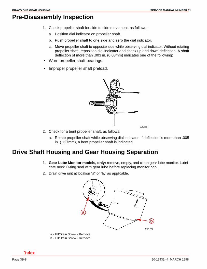
Pre-Disassembly Inspection
1. Check propeller shaft for side to side movement, as follows:
a. Position dial indicator on propeller shaft.
b. Push propeller shaft to one side and zero the dial indicator.
c. Move propeller shaft to opposite side while observing dial indicator. Without rotatingpropeller shaft, reposition dial indicator and check up and down deflection. A shaftdeflection of more than .003 in. (0.08mm) indicates one of the following:
• Worn propeller shaft bearings.
• Improper propeller shaft preload.
22086
2. Check for a bent propeller shaft, as follows:
a. Rotate propeller shaft while observing dial indicator. If deflection is more than .005in. (.127mm), a bent propeller shaft is indicated.
Drive Shaft Housing and Gear Housing Separation
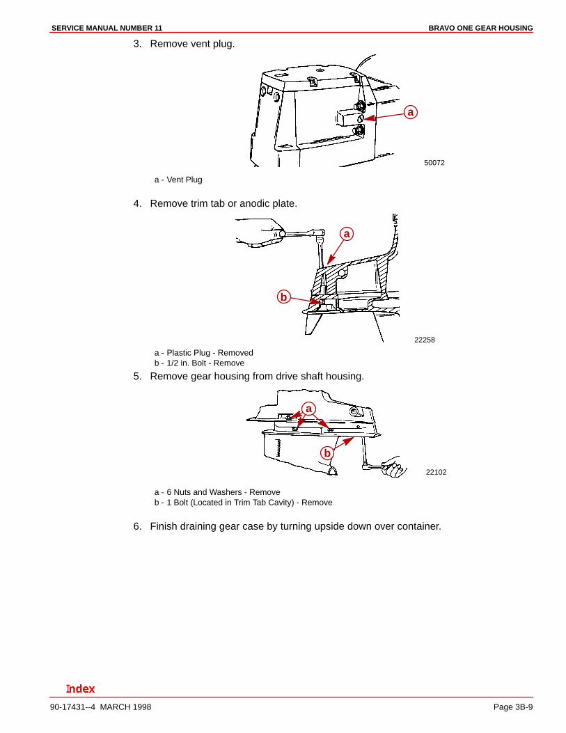
1. Gear Lube Monitor models, only: remove, empty, and clean gear lube monitor. Lubri-cate neck O-ring seal with gear lube before replacing monitor cap.
2. Drain drive unit at location “a” or “b,” as applicable.
22103
a
b
a - Fill/Drain Screw - Removeb - Fill/Drain Screw - Remove
BRAVO ONE GEAR HOUSINGSERVICE MANUAL NUMBER 11
90-17431--4 MARCH 1998 Page 3B-9
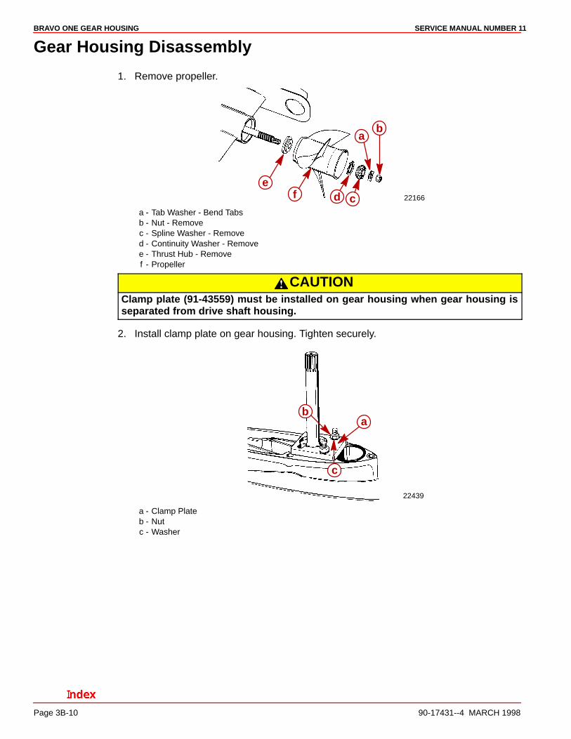
3. Remove vent plug.
50072
a
a - Vent Plug
4. Remove trim tab or anodic plate.
22258
a
b
a - Plastic Plug - Removedb - 1/2 in. Bolt - Remove
5. Remove gear housing from drive shaft housing.
22102
a
b
a - 6 Nuts and Washers - Removeb - 1 Bolt (Located in Trim Tab Cavity) - Remove
6. Finish draining gear case by turning upside down over container.
BRAVO ONE GEAR HOUSING SERVICE MANUAL NUMBER 11
Page 3B-10 90-17431--4 MARCH 1998
Gear Housing Disassembly
1. Remove propeller.
22166
ab
cde
f
a - Tab Washer - Bend Tabsb - Nut - Removec - Spline Washer - Removed - Continuity Washer - Removee - Thrust Hub - Removef - Propeller
CAUTIONClamp plate (91-43559) must be installed on gear housing when gear housing isseparated from drive shaft housing.
2. Install clamp plate on gear housing. Tighten securely.
22439
ab
c
a - Clamp Plateb - Nutc - Washer
BRAVO ONE GEAR HOUSINGSERVICE MANUAL NUMBER 11
90-17431--4 MARCH 1998 Page 3B-11
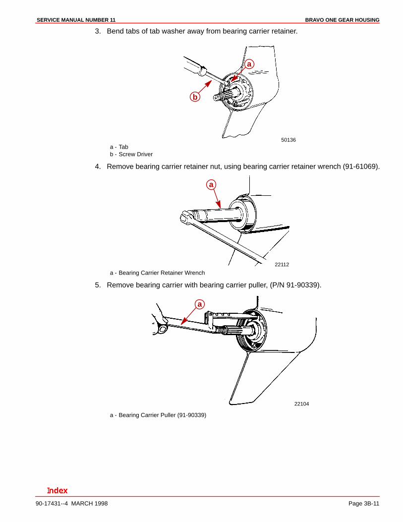
3. Bend tabs of tab washer away from bearing carrier retainer.
50136
a
b
a - Tabb - Screw Driver
4. Remove bearing carrier retainer nut, using bearing carrier retainer wrench (91-61069).
22112
a
a - Bearing Carrier Retainer Wrench
5. Remove bearing carrier with bearing carrier puller, (P/N 91-90339).
22104
a
a - Bearing Carrier Puller (91-90339)
BRAVO ONE GEAR HOUSING SERVICE MANUAL NUMBER 11
Page 3B-12 90-17431--4 MARCH 1998
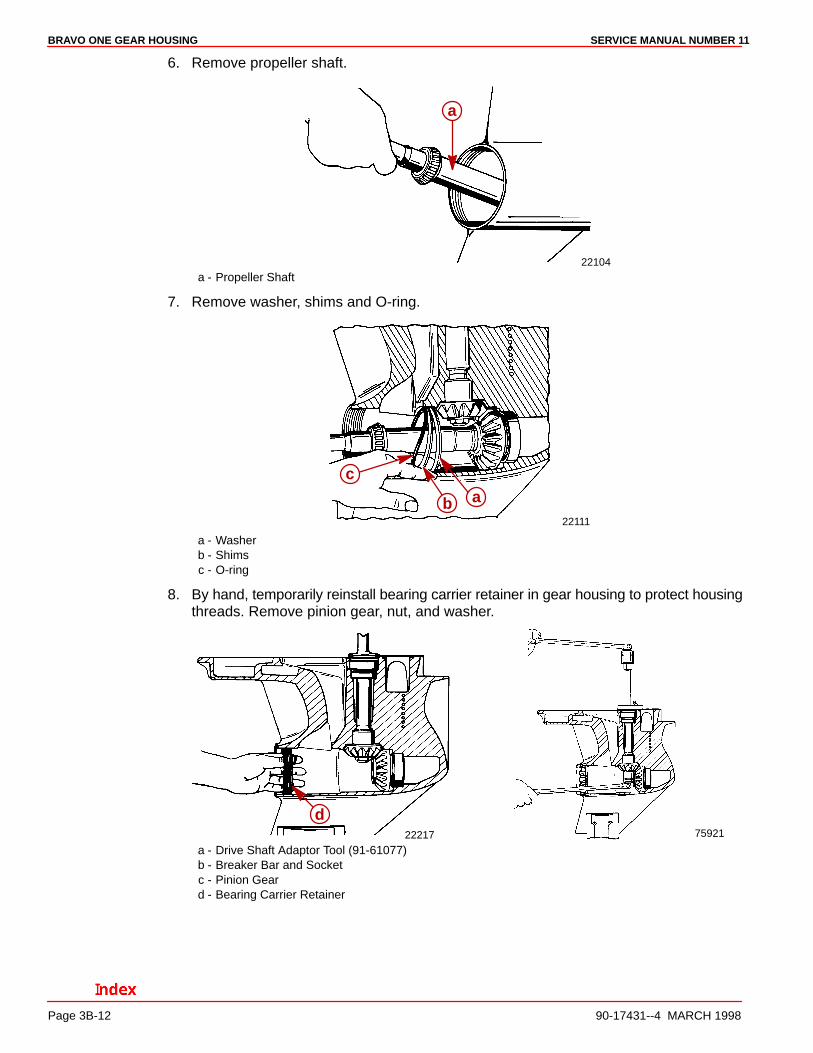
6. Remove propeller shaft.
22104
a
a - Propeller Shaft
7. Remove washer, shims and O-ring.
22111
ab
c
a - Washerb - Shimsc - O-ring
8. By hand, temporarily reinstall bearing carrier retainer in gear housing to protect housingthreads. Remove pinion gear, nut, and washer.
22217 75921
d
a - Drive Shaft Adaptor Tool (91-61077)b - Breaker Bar and Socketc - Pinion Geard - Bearing Carrier Retainer
BRAVO ONE GEAR HOUSINGSERVICE MANUAL NUMBER 11
90-17431--4 MARCH 1998 Page 3B-13
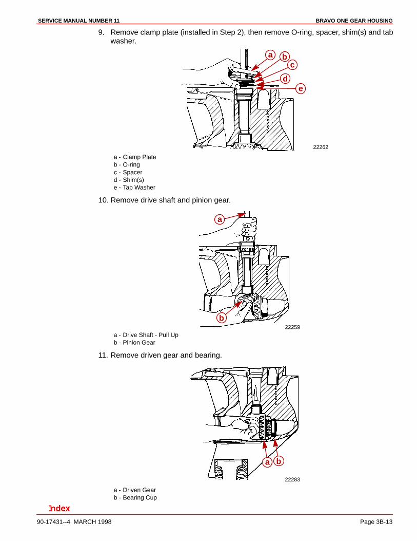
9. Remove clamp plate (installed in Step 2), then remove O-ring, spacer, shim(s) and tabwasher.
22262
a bc
de
a - Clamp Plateb - O-ringc - Spacerd - Shim(s)e - Tab Washer
10. Remove drive shaft and pinion gear.
22259
a
b
a - Drive Shaft - Pull Upb - Pinion Gear
11. Remove driven gear and bearing.
22283
a b
a - Driven Gearb - Bearing Cup
BRAVO ONE GEAR HOUSING SERVICE MANUAL NUMBER 11
Page 3B-14 90-17431--4 MARCH 1998
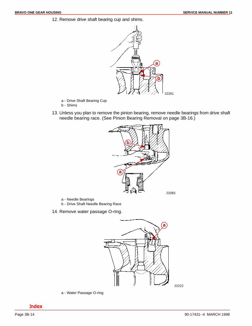
12. Remove drive shaft bearing cup and shims.
22261
a
b
a - Drive Shaft Bearing Cupb - Shims
13. Unless you plan to remove the pinion bearing, remove needle bearings from drive shaftneedle bearing race. (See Pinion Bearing Removal on page 3B-16.)
22083
a
b
a - Needle Bearingsb - Drive Shaft Needle Bearing Race
14. Remove water passage O-ring.
22222
a
a - Water Passage O-ring
BRAVO ONE GEAR HOUSINGSERVICE MANUAL NUMBER 11
90-17431--4 MARCH 1998 Page 3B-15
Component Servicing
Drive Shaft and Pinion Bearing Inspection and Cleaning1. The condition of the drive shaft tapered bearing cups is an indication of the condition of
the tapered roller bearings on the drive shaft. Replace bearing and bearing cup if cupis pitted, grooved, scored, worn uneven, discolored from overheating, or has embeddedmetal particles.
2. The condition of the bearing surface on drive shaft at needle bearing location is an in-dication of the condition of needle bearings. Replace needles and sleeve if pitted,grooved, scored, worn uneven, discolored from overheating, or has embedded metalparticles.
3. Inspect splines for worn or twisted condition. Replacement of drive shaft is necessaryif either condition exists.
4. Clean all parts that are to be reused with solvent. Dry parts completely using com-pressed air, being careful not to spin bearings.
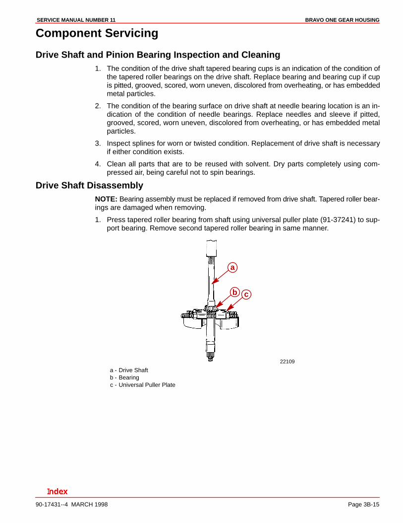
Drive Shaft DisassemblyNOTE: Bearing assembly must be replaced if removed from drive shaft. Tapered roller bear-ings are damaged when removing.
1. Press tapered roller bearing from shaft using universal puller plate (91-37241) to sup-port bearing. Remove second tapered roller bearing in same manner.
22109
a
b c
a - Drive Shaftb - Bearingc - Universal Puller Plate
BRAVO ONE GEAR HOUSING SERVICE MANUAL NUMBER 11
Page 3B-16 90-17431--4 MARCH 1998
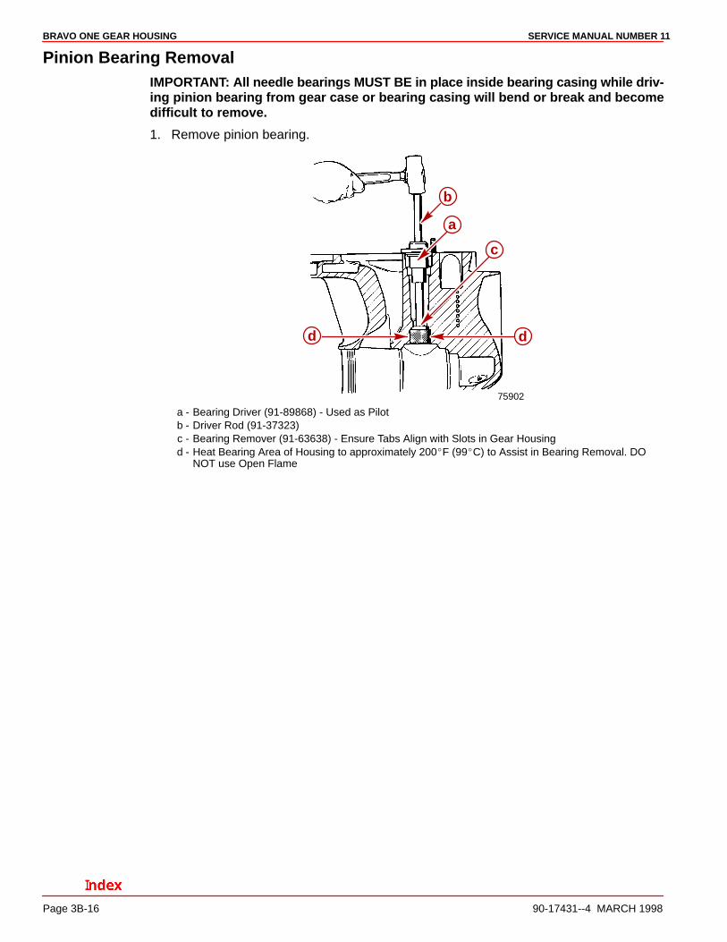
Pinion Bearing RemovalIMPORTANT: All needle bearings MUST BE in place inside bearing casing while driv-ing pinion bearing from gear case or bearing casing will bend or break and becomedifficult to remove.
1. Remove pinion bearing.
75902
b
a
c
d d
a - Bearing Driver (91-89868) - Used as Pilotb - Driver Rod (91-37323)c - Bearing Remover (91-63638) - Ensure Tabs Align with Slots in Gear Housingd - Heat Bearing Area of Housing to approximately 200�F (99�C) to Assist in Bearing Removal. DO
NOT use Open Flame
BRAVO ONE GEAR HOUSINGSERVICE MANUAL NUMBER 11
90-17431--4 MARCH 1998 Page 3B-17
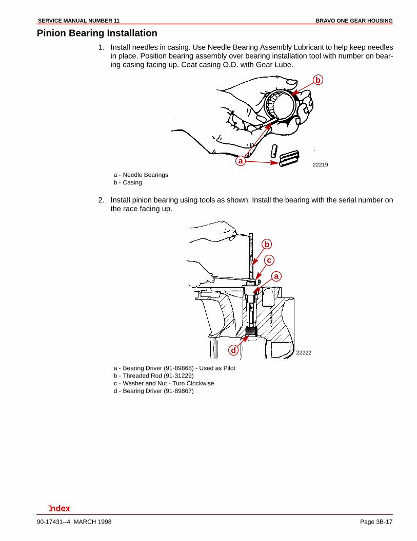
Pinion Bearing Installation1. Install needles in casing. Use Needle Bearing Assembly Lubricant to help keep needles
in place. Position bearing assembly over bearing installation tool with number on bear-ing casing facing up. Coat casing O.D. with Gear Lube.
22219a
b
a - Needle Bearingsb - Casing
2. Install pinion bearing using tools as shown. Install the bearing with the serial number onthe race facing up.
22222
a
b
c
d
a - Bearing Driver (91-89868) - Used as Pilotb - Threaded Rod (91-31229)c - Washer and Nut - Turn Clockwised - Bearing Driver (91-89867)
BRAVO ONE GEAR HOUSING SERVICE MANUAL NUMBER 11
Page 3B-18 90-17431--4 MARCH 1998
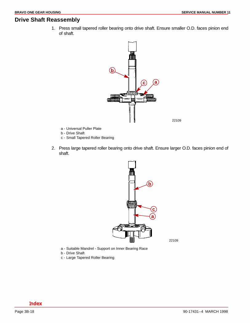
Drive Shaft Reassembly1. Press small tapered roller bearing onto drive shaft. Ensure smaller O.D. faces pinion end
of shaft.
22109
a
b
c
a - Universal Puller Plateb - Drive Shaftc - Small Tapered Roller Bearing
2. Press large tapered roller bearing onto drive shaft. Ensure larger O.D. faces pinion end ofshaft.
22109
a
b
c
a - Suitable Mandrel - Support on Inner Bearing Raceb - Drive Shaftc - Large Tapered Roller Bearing
BRAVO ONE GEAR HOUSINGSERVICE MANUAL NUMBER 11
90-17431--4 MARCH 1998 Page 3B-19
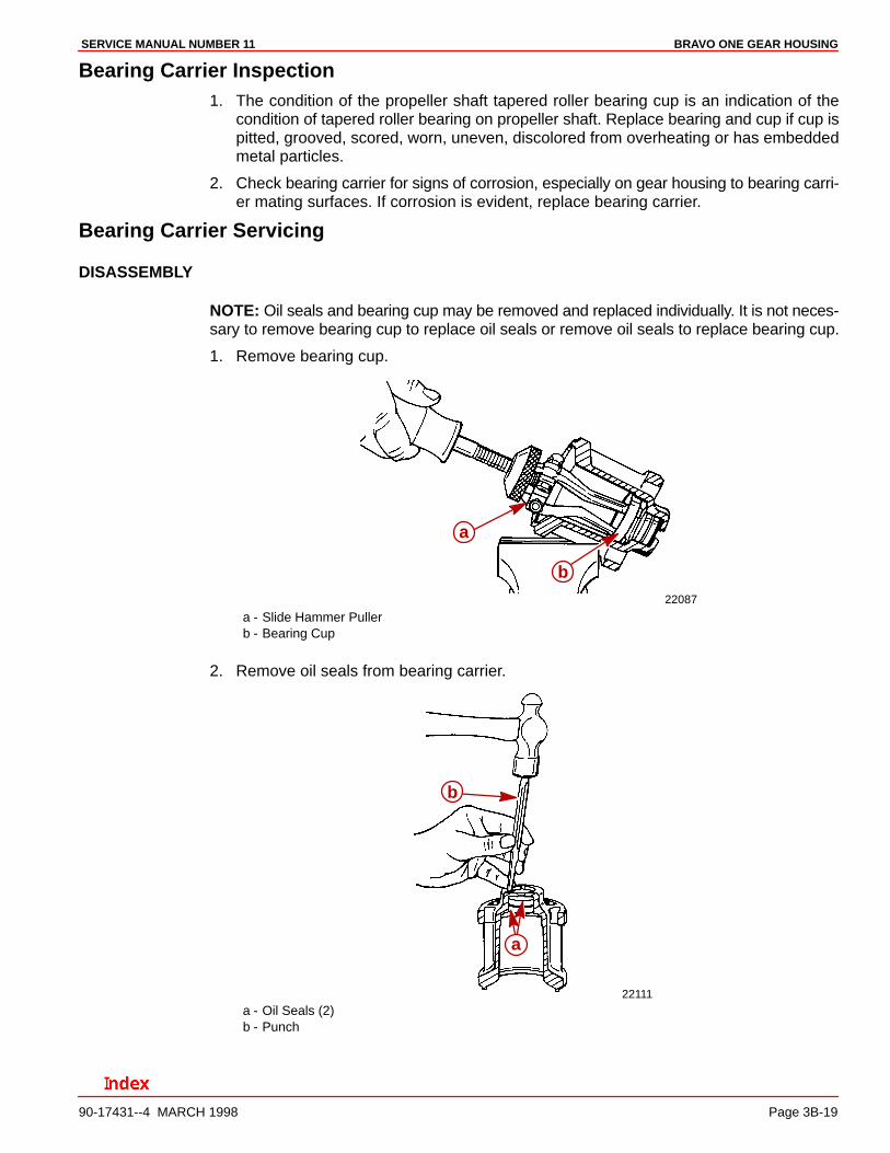
Bearing Carrier Inspection1. The condition of the propeller shaft tapered roller bearing cup is an indication of the
condition of tapered roller bearing on propeller shaft. Replace bearing and cup if cup ispitted, grooved, scored, worn, uneven, discolored from overheating or has embeddedmetal particles.
2. Check bearing carrier for signs of corrosion, especially on gear housing to bearing carri-er mating surfaces. If corrosion is evident, replace bearing carrier.
Bearing Carrier Servicing
DISASSEMBLY
NOTE: Oil seals and bearing cup may be removed and replaced individually. It is not neces-sary to remove bearing cup to replace oil seals or remove oil seals to replace bearing cup.
1. Remove bearing cup.
22087
a
b
a - Slide Hammer Pullerb - Bearing Cup
2. Remove oil seals from bearing carrier.
22111
a
b
a - Oil Seals (2)b - Punch
BRAVO ONE GEAR HOUSING SERVICE MANUAL NUMBER 11
Page 3B-20 90-17431--4 MARCH 1998
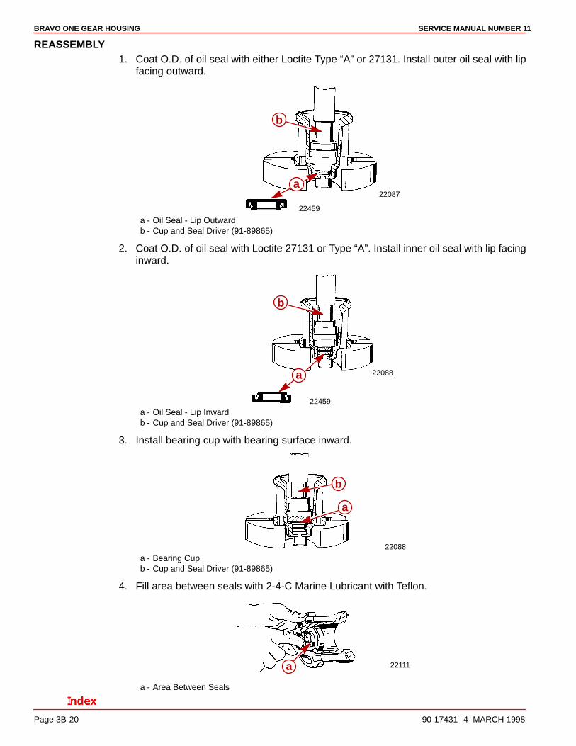
REASSEMBLY1. Coat O.D. of oil seal with either Loctite Type “A” or 27131. Install outer oil seal with lip
facing outward.
22087
22459
a
b
a - Oil Seal - Lip Outwardb - Cup and Seal Driver (91-89865)
2. Coat O.D. of oil seal with Loctite 27131 or Type “A”. Install inner oil seal with lip facinginward.
22088
22459
b
a
a - Oil Seal - Lip Inwardb - Cup and Seal Driver (91-89865)
3. Install bearing cup with bearing surface inward.
22088
a
b
a - Bearing Cupb - Cup and Seal Driver (91-89865)
4. Fill area between seals with 2-4-C Marine Lubricant with Teflon.
22111a
a - Area Between Seals
BRAVO ONE GEAR HOUSINGSERVICE MANUAL NUMBER 11
90-17431--4 MARCH 1998 Page 3B-21
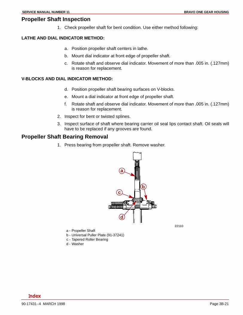
Propeller Shaft Inspection1. Check propeller shaft for bent condition. Use either method following:
LATHE AND DIAL INDICATOR METHOD:
a. Position propeller shaft centers in lathe.
b. Mount dial indicator at front edge of propeller shaft.
c. Rotate shaft and observe dial indicator. Movement of more than .005 in. (.127mm)is reason for replacement.
V-BLOCKS AND DIAL INDICATOR METHOD:
d. Position propeller shaft bearing surfaces on V-blocks.
e. Mount a dial indicator at front edge of propeller shaft.
f. Rotate shaft and observe dial indicator. Movement of more than .005 in. (.127mm)is reason for replacement.
2. Inspect for bent or twisted splines.
3. Inspect surface of shaft where bearing carrier oil seal lips contact shaft. Oil seals willhave to be replaced if any grooves are found.
Propeller Shaft Bearing Removal1. Press bearing from propeller shaft. Remove washer.
22110
a
bc
d
a - Propeller Shaftb - Universal Puller Plate (91-37241)c - Tapered Roller Bearingd - Washer
BRAVO ONE GEAR HOUSING SERVICE MANUAL NUMBER 11
Page 3B-22 90-17431--4 MARCH 1998
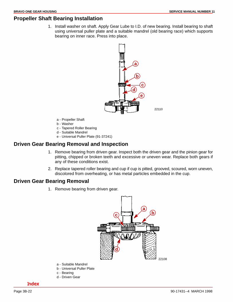
Propeller Shaft Bearing Installation1. Install washer on shaft. Apply Gear Lube to I.D. of new bearing. Install bearing to shaft
using universal puller plate and a suitable mandrel (old bearing race) which supportsbearing on inner race. Press into place.
22110
a
b
cd
e
a - Propeller Shaftb - Washerc - Tapered Roller Bearingd - Suitable Mandrele - Universal Puller Plate (91-37241)
Driven Gear Bearing Removal and Inspection1. Remove bearing from driven gear. Inspect both the driven gear and the pinion gear for
pitting, chipped or broken teeth and excessive or uneven wear. Replace both gears ifany of these conditions exist.
2. Replace tapered roller bearing and cup if cup is pitted, grooved, scoured, worn uneven,discolored from overheating, or has metal particles embedded in the cup.
Driven Gear Bearing Removal1. Remove bearing from driven gear.
22108
abc
d
a - Suitable Mandrelb - Universal Puller Platec - Bearingd - Driven Gear
BRAVO ONE GEAR HOUSINGSERVICE MANUAL NUMBER 11
90-17431--4 MARCH 1998 Page 3B-23
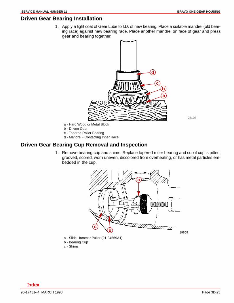
Driven Gear Bearing Installation1. Apply a light coat of Gear Lube to I.D. of new bearing. Place a suitable mandrel (old bear-
ing race) against new bearing race. Place another mandrel on face of gear and pressgear and bearing together.
22108
ab
c
d
a - Hard Wood or Metal Blockb - Driven Gearc - Tapered Roller Bearingd - Mandrel - Contacting Inner Race
Driven Gear Bearing Cup Removal and Inspection1. Remove bearing cup and shims. Replace tapered roller bearing and cup if cup is pitted,
grooved, scored, worn uneven, discolored from overheating, or has metal particles em-bedded in the cup.
19808
a
bc
a - Slide Hammer Puller (91-34569A1)b - Bearing Cupc - Shims

BRAVO ONE GEAR HOUSING SERVICE MANUAL NUMBER 11
Page 3B-24 90-17431--4 MARCH 1998
Driven Gear Bearing Cup Installation1. Install driven gear bearing cup with original thickness shims(s). Ensure cup is not
canted. Coat cup O.D. with Gear Lube.
75922
a b
cd
a - Shim(s)b - Bearing Cupc - Driver (P/N 91-31106)d - Old Propeller Shaft or Driver Rod
Speedometer Water Tube Pickup Inspection and Cleaning1. Inspect opening (pitot tube), on leading edge of gear housing, for obstruction. Clean
opening with a short piece of wire, if necessary. If obstruction can not be removed withwire, carefully reopen tube using a 5/64 in. (2mm) diameter drill bit. Do not drill beyonda depth of 2-7/16 in. (62mm).
22462
a
a - Pitot Tube
2. Inspect water tube seal for nicks, cuts, or distortion. Replace if necessary.
22085
a
a - Water Tube Seal
BRAVO ONE GEAR HOUSINGSERVICE MANUAL NUMBER 11
90-17431--4 MARCH 1998 Page 3B-25
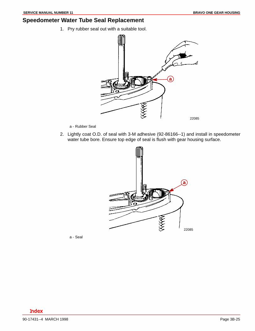
Speedometer Water Tube Seal Replacement1. Pry rubber seal out with a suitable tool.
22085
a
a - Rubber Seal
2. Lightly coat O.D. of seal with 3-M adhesive (92-86166--1) and install in speedometerwater tube bore. Ensure top edge of seal is flush with gear housing surface.
22085
a
a - Seal
BRAVO ONE GEAR HOUSING SERVICE MANUAL NUMBER 11
Page 3B-26 90-17431--4 MARCH 1998
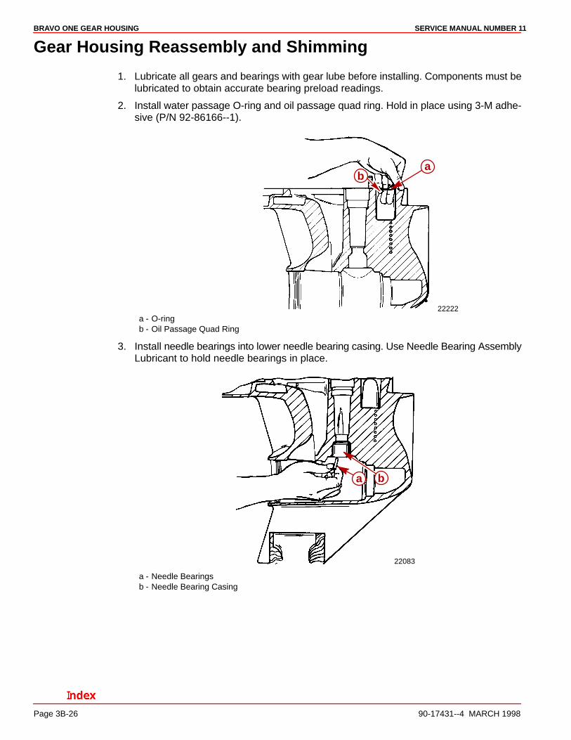
Gear Housing Reassembly and Shimming
1. Lubricate all gears and bearings with gear lube before installing. Components must belubricated to obtain accurate bearing preload readings.
2. Install water passage O-ring and oil passage quad ring. Hold in place using 3-M adhe-sive (P/N 92-86166--1).
22222
ab
a - O-ringb - Oil Passage Quad Ring
3. Install needle bearings into lower needle bearing casing. Use Needle Bearing AssemblyLubricant to hold needle bearings in place.
22083
a b
a - Needle Bearingsb - Needle Bearing Casing
BRAVO ONE GEAR HOUSINGSERVICE MANUAL NUMBER 11
90-17431--4 MARCH 1998 Page 3B-27
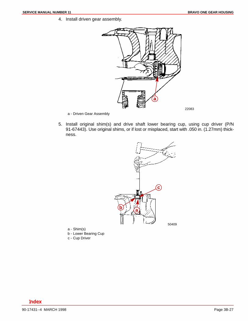
4. Install driven gear assembly.
22083
a
a - Driven Gear Assembly
5. Install original shim(s) and drive shaft lower bearing cup, using cup driver (P/N91-67443). Use original shims, or if lost or misplaced, start with .050 in. (1.27mm) thick-ness.
50409
ab
c
a - Shim(s)b - Lower Bearing Cupc - Cup Driver
BRAVO ONE GEAR HOUSING SERVICE MANUAL NUMBER 11
Page 3B-28 90-17431--4 MARCH 1998
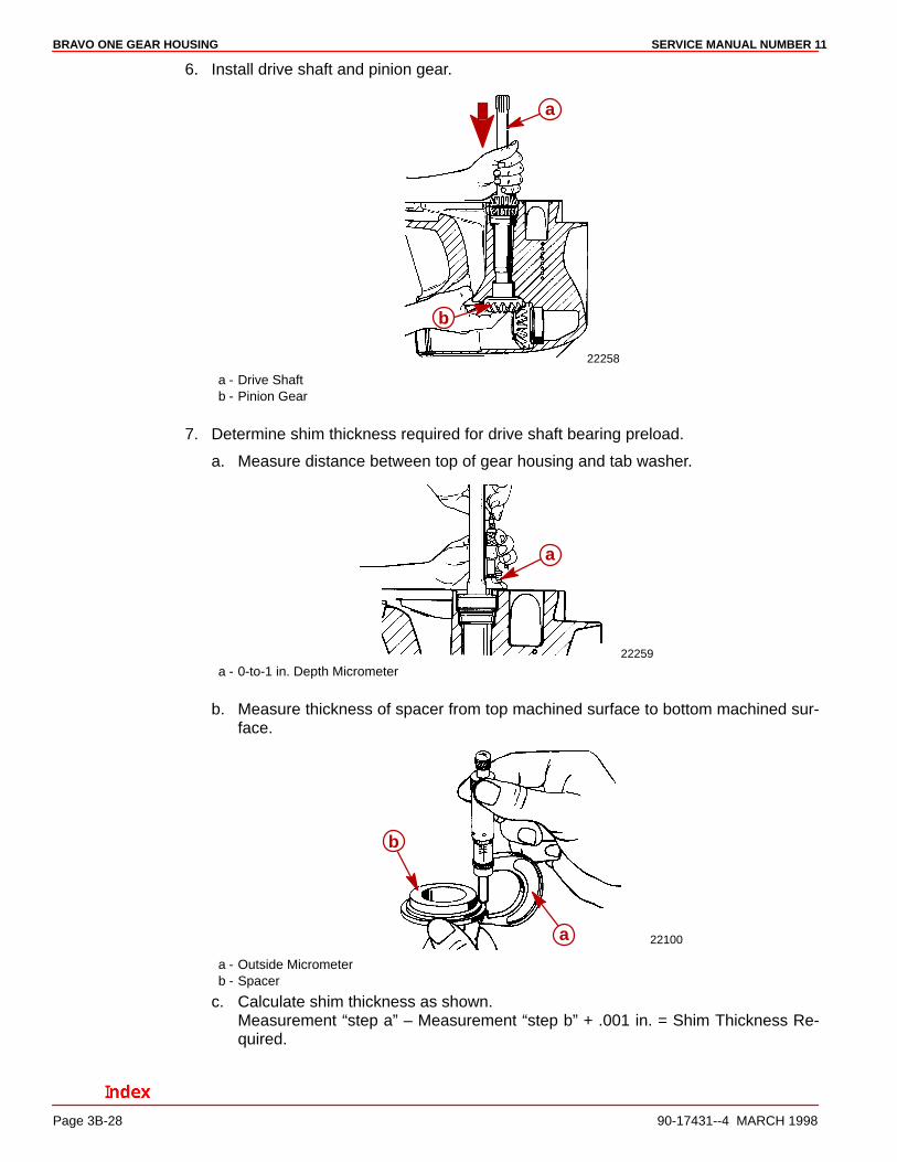
6. Install drive shaft and pinion gear.
22258
a
b
a - Drive Shaftb - Pinion Gear
7. Determine shim thickness required for drive shaft bearing preload.
a. Measure distance between top of gear housing and tab washer.
22259
a
a - 0-to-1 in. Depth Micrometer
b. Measure thickness of spacer from top machined surface to bottom machined sur-face.
a
b
22100
a - Outside Micrometerb - Spacer
c. Calculate shim thickness as shown.Measurement “step a” – Measurement “step b” + .001 in. = Shim Thickness Re-quired.
BRAVO ONE GEAR HOUSINGSERVICE MANUAL NUMBER 11
90-17431--4 MARCH 1998 Page 3B-29
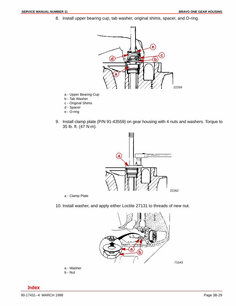
8. Install upper bearing cup, tab washer, original shims, spacer, and O-ring.
22259
a
bc
d
e
a - Upper Bearing Cupb - Tab Washerc - Original Shimsd - Spacere - O-ring
9. Install clamp plate (P/N 91-43559) on gear housing with 4 nuts and washers. Torque to35 lb. ft. (47 N·m).
22262
a
a - Clamp Plate
10. Install washer, and apply either Loctite 27131 to threads of new nut.
71543
ab
a - Washerb - Nut
BRAVO ONE GEAR HOUSING SERVICE MANUAL NUMBER 11
Page 3B-30 90-17431--4 MARCH 1998
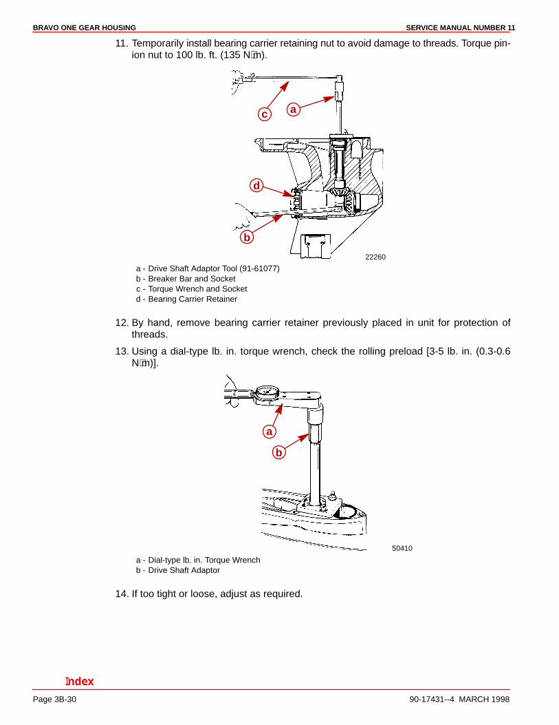
11. Temporarily install bearing carrier retaining nut to avoid damage to threads. Torque pin-ion nut to 100 lb. ft. (135 N⋅m).
22260
a
b
c
d
a - Drive Shaft Adaptor Tool (91-61077)b - Breaker Bar and Socketc - Torque Wrench and Socketd - Bearing Carrier Retainer
12. By hand, remove bearing carrier retainer previously placed in unit for protection ofthreads.
13. Using a dial-type lb. in. torque wrench, check the rolling preload [3-5 lb. in. (0.3-0.6N⋅m)].
50410
a
b
a - Dial-type lb. in. Torque Wrenchb - Drive Shaft Adaptor
14. If too tight or loose, adjust as required.
BRAVO ONE GEAR HOUSINGSERVICE MANUAL NUMBER 11
90-17431--4 MARCH 1998 Page 3B-31
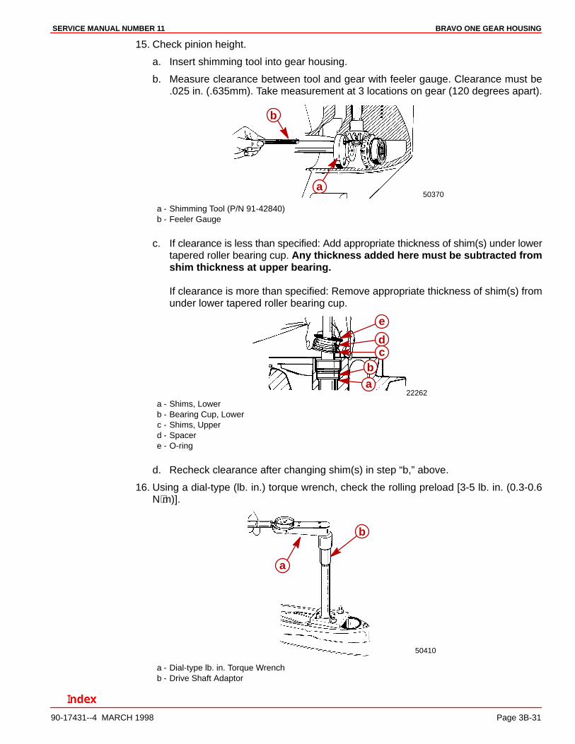
15. Check pinion height.
a. Insert shimming tool into gear housing.
b. Measure clearance between tool and gear with feeler gauge. Clearance must be.025 in. (.635mm). Take measurement at 3 locations on gear (120 degrees apart).
50370a
b
a - Shimming Tool (P/N 91-42840)b - Feeler Gauge
c. If clearance is less than specified: Add appropriate thickness of shim(s) under lowertapered roller bearing cup. Any thickness added here must be subtracted fromshim thickness at upper bearing.
If clearance is more than specified: Remove appropriate thickness of shim(s) fromunder lower tapered roller bearing cup.
22262ab
cd
e
a - Shims, Lowerb - Bearing Cup, Lowerc - Shims, Upperd - Spacere - O-ring
d. Recheck clearance after changing shim(s) in step “b,” above.
16. Using a dial-type (lb. in.) torque wrench, check the rolling preload [3-5 lb. in. (0.3-0.6N⋅m)].
50410
a
b
a - Dial-type lb. in. Torque Wrenchb - Drive Shaft Adaptor
BRAVO ONE GEAR HOUSING SERVICE MANUAL NUMBER 11
Page 3B-32 90-17431--4 MARCH 1998
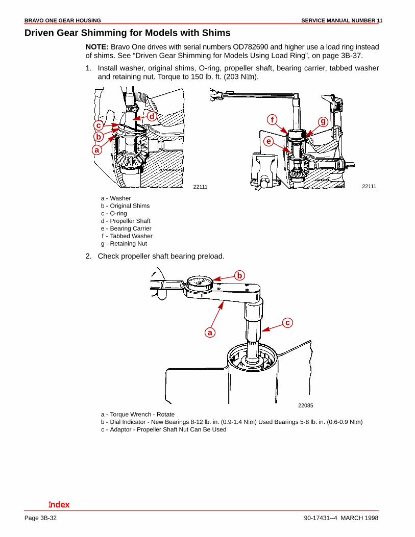
Driven Gear Shimming for Models with ShimsNOTE: Bravo One drives with serial numbers OD782690 and higher use a load ring insteadof shims. See “Driven Gear Shimming for Models Using Load Ring”, on page 3B-37.
1. Install washer, original shims, O-ring, propeller shaft, bearing carrier, tabbed washerand retaining nut. Torque to 150 lb. ft. (203 N⋅m).
22111 22111
a
bc
d
e
f g
a - Washerb - Original Shimsc - O-ringd - Propeller Shafte - Bearing Carrierf - Tabbed Washerg - Retaining Nut
2. Check propeller shaft bearing preload.
22085
ac
b
a - Torque Wrench - Rotateb - Dial Indicator - New Bearings 8-12 lb. in. (0.9-1.4 N⋅m) Used Bearings 5-8 lb. in. (0.6-0.9 N⋅m)c - Adaptor - Propeller Shaft Nut Can Be Used
BRAVO ONE GEAR HOUSINGSERVICE MANUAL NUMBER 11
90-17431--4 MARCH 1998 Page 3B-33
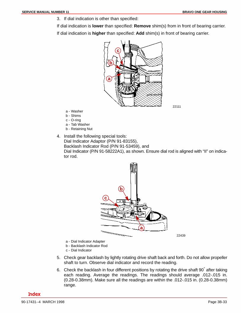
3. If dial indication is other than specified:
If dial indication is lower than specified: Remove shim(s) from in front of bearing carrier.
If dial indication is higher than specified: Add shim(s) in front of bearing carrier.
22111
a
b
c
a - Washerb - Shimsc - O-ringa - Tab Washerb - Retaining Nut
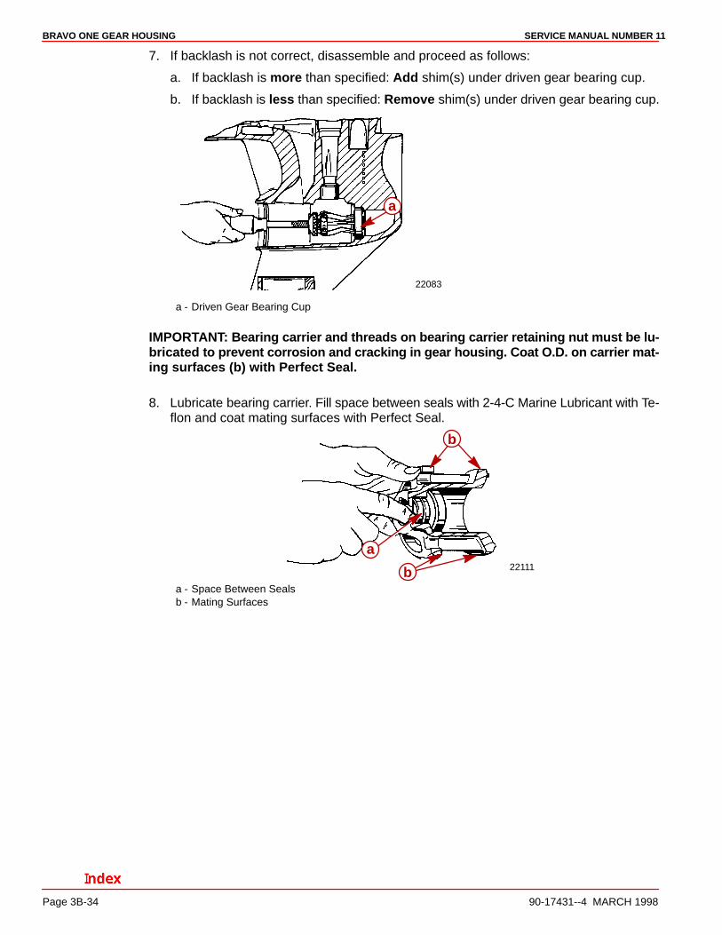
4. Install the following special tools:Dial Indicator Adaptor (P/N 91-83155),Backlash Indicator Rod (P/N 91-53459), andDial Indicator (P/N 91-58222A1), as shown. Ensure dial rod is aligned with “II” on indica-tor rod.
22439
a
b
c
a - Dial Indicator Adapterb - Backlash Indicator Rodc - Dial Indicator
5. Check gear backlash by lightly rotating drive shaft back and forth. Do not allow propellershaft to turn. Observe dial indicator and record the reading.
6. Check the backlash in four different positions by rotating the drive shaft 90° after takingeach reading. Average the readings. The readings should average .012-.015 in.(0.28-0.38mm). Make sure all the readings are within the .012-.015 in. (0.28-0.38mm)range.
BRAVO ONE GEAR HOUSING SERVICE MANUAL NUMBER 11
Page 3B-34 90-17431--4 MARCH 1998
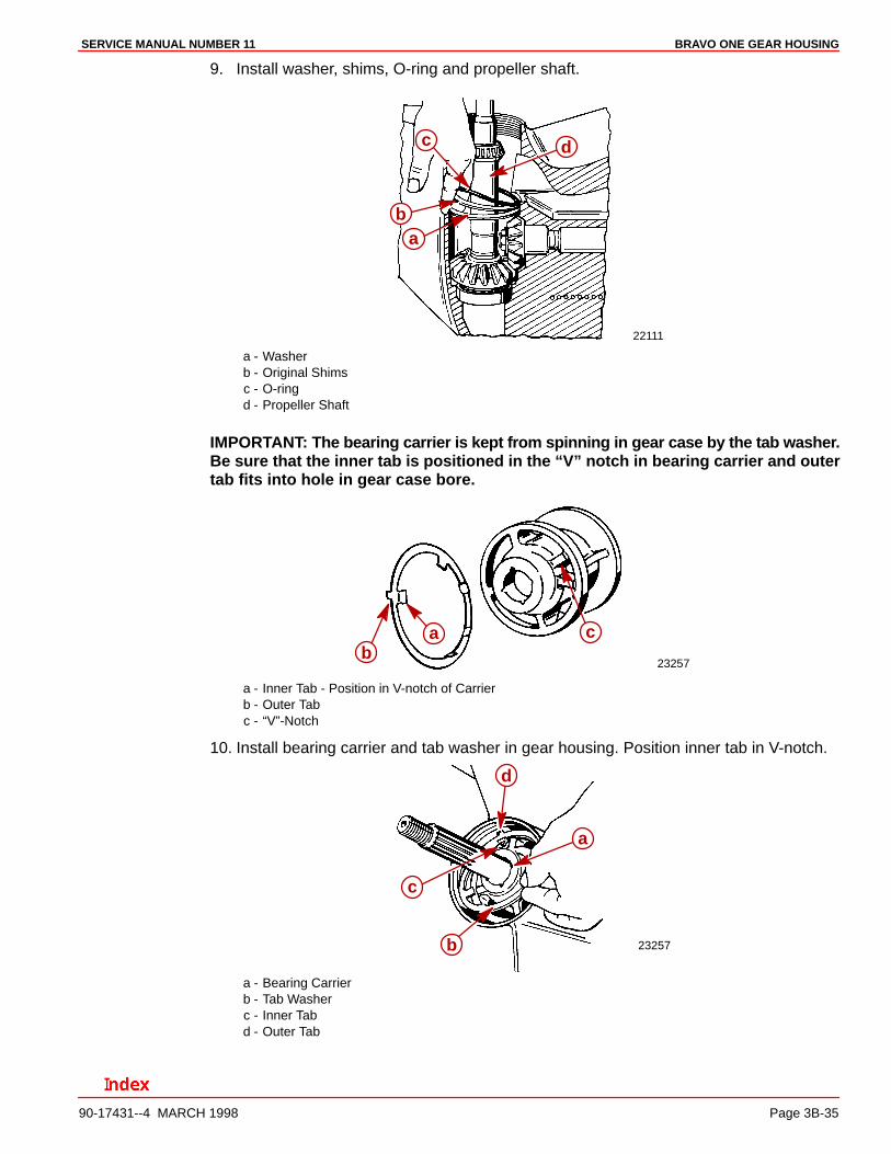
7. If backlash is not correct, disassemble and proceed as follows:
a. If backlash is more than specified: Add shim(s) under driven gear bearing cup.
b. If backlash is less than specified: Remove shim(s) under driven gear bearing cup.
22083
a
a - Driven Gear Bearing Cup
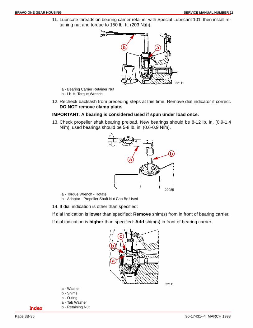
IMPORTANT: Bearing carrier and threads on bearing carrier retaining nut must be lu-bricated to prevent corrosion and cracking in gear housing. Coat O.D. on carrier mat-ing surfaces (b) with Perfect Seal.
8. Lubricate bearing carrier. Fill space between seals with 2-4-C Marine Lubricant with Te-flon and coat mating surfaces with Perfect Seal.
22111
a
b
ba - Space Between Sealsb - Mating Surfaces
BRAVO ONE GEAR HOUSINGSERVICE MANUAL NUMBER 11
90-17431--4 MARCH 1998 Page 3B-35
9. Install washer, shims, O-ring and propeller shaft.
22111
ab
c d
a - Washerb - Original Shimsc - O-ringd - Propeller Shaft
IMPORTANT: The bearing carrier is kept from spinning in gear case by the tab washer.Be sure that the inner tab is positioned in the “V” notch in bearing carrier and outertab fits into hole in gear case bore.
23257
ab
c
a - Inner Tab - Position in V-notch of Carrierb - Outer Tabc - “V”-Notch
10. Install bearing carrier and tab washer in gear housing. Position inner tab in V-notch.
23257
a
b
c
d
a - Bearing Carrierb - Tab Washerc - Inner Tabd - Outer Tab
BRAVO ONE GEAR HOUSING SERVICE MANUAL NUMBER 11
Page 3B-36 90-17431--4 MARCH 1998
11. Lubricate threads on bearing carrier retainer with Special Lubricant 101; then install re-taining nut and torque to 150 lb. ft. (203 N⋅m).
22111
ab
a - Bearing Carrier Retainer Nutb - Lb. ft. Torque Wrench
12. Recheck backlash from preceding steps at this time. Remove dial indicator if correct.DO NOT remove clamp plate.
IMPORTANT: A bearing is considered used if spun under load once.
13. Check propeller shaft bearing preload. New bearings should be 8-12 lb. in. (0.9-1.4N⋅m). used bearings should be 5-8 lb. in. (0.6-0.9 N⋅m).
22085
ab
a - Torque Wrench - Rotateb - Adaptor - Propeller Shaft Nut Can Be Used
14. If dial indication is other than specified:
If dial indication is lower than specified: Remove shim(s) from in front of bearing carrier.
If dial indication is higher than specified: Add shim(s) in front of bearing carrier.
22111
a
b
c
a - Washerb - Shimsc - O-ringa - Tab Washerb - Retaining Nut
BRAVO ONE GEAR HOUSINGSERVICE MANUAL NUMBER 11
90-17431--4 MARCH 1998 Page 3B-37
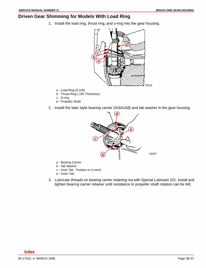
Driven Gear Shimming for Models With Load Ring1. Install the load ring, thrust ring, and o-ring into the gear housing.
22111
ab
c
d
a - Load Ring (0.105)b - Thrust Ring (.105 Thickness)c - O-ringd - Propeller Shaft
2. Install the later style bearing carrier (41641A8) and tab washer in the gear housing.
23257
a
b
c
d
a - Bearing Carrierb - Tab Washerc - Inner Tab - Position in V-notchd - Outer Tab
3. Lubricate threads on bearing carrier retaining nut with Special Lubricant 101. Install andtighten bearing carrier retainer until resistance to propeller shaft rotation can be felt.
BRAVO ONE GEAR HOUSING SERVICE MANUAL NUMBER 11
Page 3B-38 90-17431--4 MARCH 1998
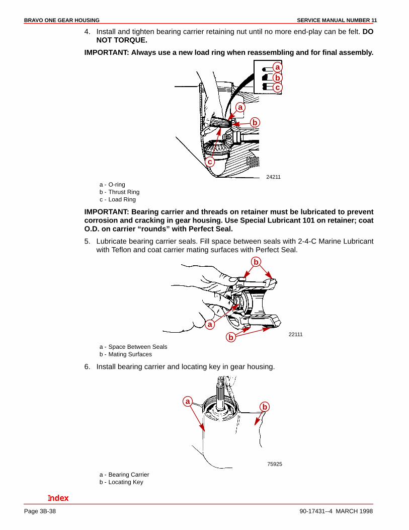
4. Install and tighten bearing carrier retaining nut until no more end-play can be felt. DONOT TORQUE.
IMPORTANT: Always use a new load ring when reassembling and for final assembly.
24211
a
b
c
ba
c
a - O-ringb - Thrust Ringc - Load Ring
IMPORTANT: Bearing carrier and threads on retainer must be lubricated to preventcorrosion and cracking in gear housing. Use Special Lubricant 101 on retainer; coatO.D. on carrier “rounds” with Perfect Seal.
5. Lubricate bearing carrier seals. Fill space between seals with 2-4-C Marine Lubricantwith Teflon and coat carrier mating surfaces with Perfect Seal.
22111
a
b
ba - Space Between Sealsb - Mating Surfaces
6. Install bearing carrier and locating key in gear housing.
75925
ab
a - Bearing Carrierb - Locating Key
BRAVO ONE GEAR HOUSINGSERVICE MANUAL NUMBER 11
90-17431--4 MARCH 1998 Page 3B-39
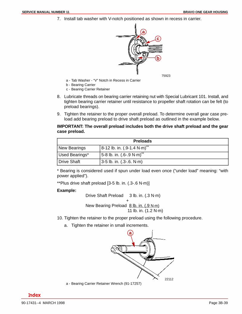
7. Install tab washer with V-notch positioned as shown in recess in carrier.
75923
a
b
c
a - Tab Washer - “V” Notch in Recess in Carrierb - Bearing Carrierc - Bearing Carrier Retainer
8. Lubricate threads on bearing carrier retaining nut with Special Lubricant 101. Install, andtighten bearing carrier retainer until resistance to propeller shaft rotation can be felt (topreload bearings).
9. Tighten the retainer to the proper overall preload. To determine overall gear case pre-load add bearing preload to drive shaft preload as outlined in the example below.
IMPORTANT: The overall preload includes both the drive shaft preload and the gearcase preload.
Preloads
New Bearings 8-12 lb. in. (.9-1.4 N·m)**
Used Bearings* 5-8 lb. in. (.6-.9 N·m)**
Drive Shaft 3-5 lb. in. (.3-.6. N·m)
* Bearing is considered used if spun under load even once (“under load” meaning: “withpower applied”).
**Plus drive shaft preload [3-5 lb. in. (.3-.6 N·m)]
Example:Drive Shaft Preload 3 lb. in. (.3 N·m)
+New Bearing Preload 8 lb. in. (.9 N·m)
11 lb. in. (1.2 N·m)
10. Tighten the retainer to the proper preload using the following procedure.
a. Tighten the retainer in small increments.
22112
a
a - Bearing Carrier Retainer Wrench (91-17257)
BRAVO ONE GEAR HOUSING SERVICE MANUAL NUMBER 11
Page 3B-40 90-17431--4 MARCH 1998
b. After tightening, check overall gear housing bearing preload at propeller shaft. Ro-tate shaft in direction of normal rotation in a smooth, steady motion.
75924
c
a
b
a - Lb. in. Torque Wrench 91-66274b - Propeller Nut (under socket)c - Shaft Rotation Direction
ALL MODELS
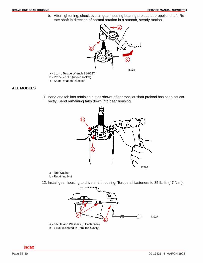
11. Bend one tab into retaining nut as shown after propeller shaft preload has been set cor-rectly. Bend remaining tabs down into gear housing.
22462
a
b
a - Tab Washerb - Retaining Nut
12. Install gear housing to drive shaft housing. Torque all fasteners to 35 lb. ft. (47 N·m).
73927ab
a - 6 Nuts and Washers (3 Each Side)b - 1 Bolt (Located in Trim Tab Cavity)
BRAVO ONE GEAR HOUSINGSERVICE MANUAL NUMBER 11
90-17431--4 MARCH 1998 Page 3B-41
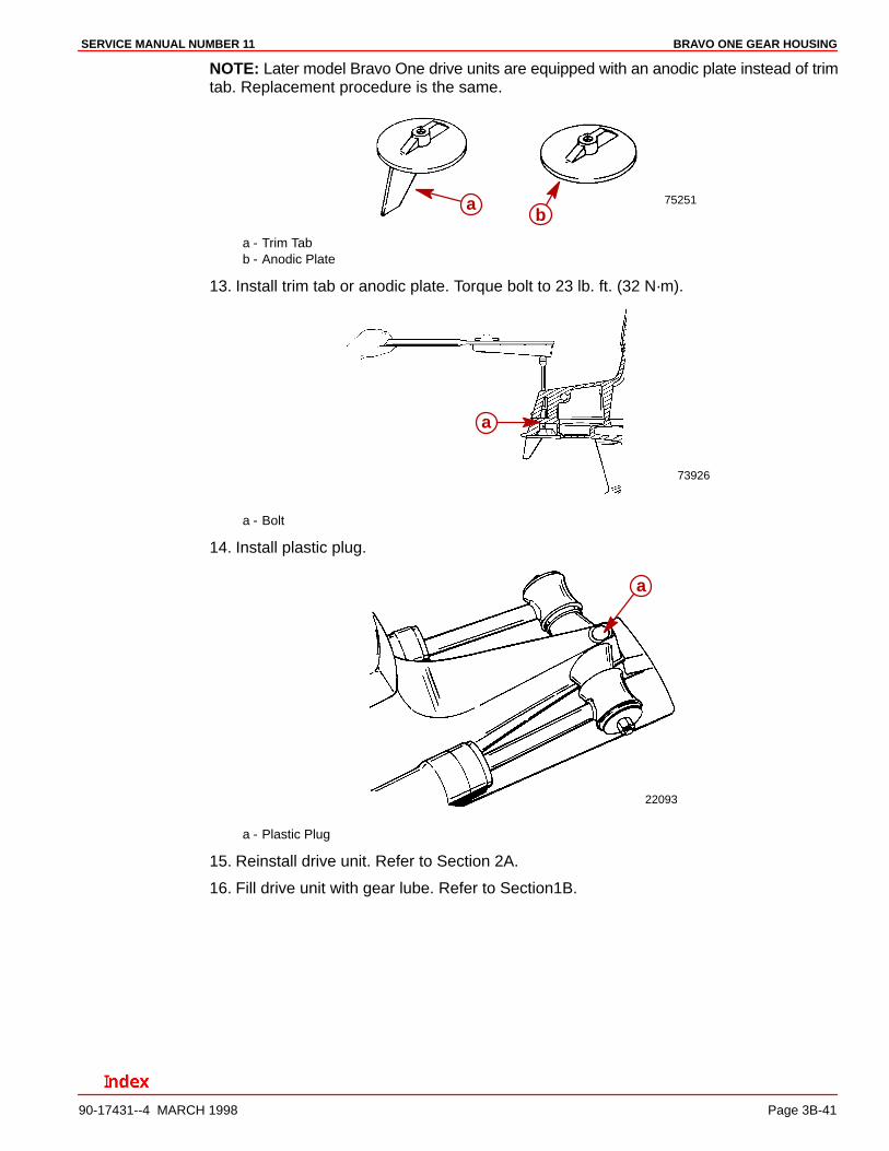
NOTE: Later model Bravo One drive units are equipped with an anodic plate instead of trimtab. Replacement procedure is the same.
75251ab
a - Trim Tabb - Anodic Plate
13. Install trim tab or anodic plate. Torque bolt to 23 lb. ft. (32 N·m).
73926
a
a - Bolt
14. Install plastic plug.
22093
a
a - Plastic Plug
15. Reinstall drive unit. Refer to Section 2A.
16. Fill drive unit with gear lube. Refer to Section1B.
BRAVO ONE GEAR HOUSING SERVICE MANUAL NUMBER 11
Page 3B-42 90-17431--4 MARCH 1998
THIS PAGE IS INTENTIONALLY BLANK