Embed Size (px)
Citation preview
ViewSonic VE150m/mbModel No.VLCDS22574-1/-1b
Service Manual
15” Color TFT LCD Display
(VE150m/VE150mb-1_SM_399 - Rev. 1a – Dec 2002)
ViewSonic “ 381 Brea Canyon Road, Walnut, California 91789 USA - (800) 888-8583
Copyright
Copyright © 2002 by ViewSonic Corporation. All rights reserved. No part of this publication may be reproduced, transmitted, transcribed, stored in a retrieval system, or translated into any language or computer language, in any form or by any means, electronic, mechanical, magnetic, optical, chemical, manual or otherwise, without the prior written permission of ViewSonic Corporation.
Disclaimer
ViewSonic makes no representations or warranties, either expressed or implied, with respect to the contents hereof and specifically disclaims any warranty of merchantability or fitness for any particular purpose. Further, ViewSonic reserves the right to revise this publication and to make changes from time to time in the contents hereof without obligation of ViewSonic to notify any person of such revision or changes.
Trademarks
ViewSonic is a registered trademark of ViewSonic Corporation. All other trademarks used within this document are the property of their respective owners.
Revision History
Revision Date Description Approval
1a 11/17/02 Initial Release DCN-2806 C.Shen
ViewSonic Corporation i Confidential -- Do Not Copy VE150m/mb
TABLE OF CONTENT
WARNING ......................................................................................1
SAFETY PRECAUTIONS...............................................................1
CHAPTER 1 PREFACE.........................................................3
CHAPTER 2 SPECIFICATIONS..........................................6
2.1 Scope.............................................................................................. 6
2.2 General Requirement.......................................................................7
2.3 Signal Interface ................................................................................7
2.4 Power................................................................................................8
2.5 Front Panel Controls and Indicators................................................ 10
2.6 Electrical Requirements .................................................................. 11
2.7 Audio............................................................................................... 12
2.8 LCD Panel....................................................................................... 13
2.9 Image Perfromance......................................................................... 14
CHAPTER 3 FRONT PANEL CONTROLS .........................15
3.1 Adjusting the Screen Image ............................................................ 15
3.2 Do the following to adjust the screen image:................................... 16
3.3 Main Menu Controls ........................................................................ 17
CHAPTER 4 CIRCUIT DESCRIPTION ...............................21
4.1 Main Board...................................................................................... 21
CHAPTER 5 TROUBLESHOOTING ................................... 26
5.1 Equipment....................................................................................... 26
5.2 Main Procedure............................................................................... 26
CHAPTER 6 THEORY OF OPERATION ............................34
6.1 System Block Diagram.................................................................... 34
6.2 System Circuitry Description ........................................................... 35
CHAPTER 7 MECHANICAL ASSEMBLY............................36
CHAPTER 8 RECOMMENDED SPARE PARTS LIST ........40
CHAPTER 9 COMPLETE PARTS LIST ...........................42
ViewSonic Corporation ii Confidential -- Do Not Copy VE150m/mb
10.2 Micro Controller and LCD power control ......................................... 54
10.3 VGA input........................................................................................ 55
10.4 Output Connector.......................................................................... 56
10.5 DC-DC ............................................................................................ 57
10.6 Audio............................................................................................... 58
CHAPTER 11 PCB LAYOUT .................................................59
CHAPTER 10 CIRCUIT DIAGRAMS.....................................53
10.1 Micro-Controller MRT MV ............................................................... 53
ViewSonic Corporation iii Confidential -- Do Not Copy VE150m/mb
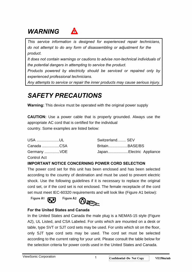
WARNINGThis service information is designed for experienced repair technicians,
do not attempt to do any form of disassembling or adjustment for the
product.
It does not contain warnings or cautions to advise non-technical individuals of
the potential dangers in attempting to service the product.
Products powered by electricity should be serviced or repaired only by
experienced professional technicians.
Any attempts to service or repair the inner products may cause serious injury.
SAFETY PRECAUTIONS Warning: This device must be operated with the original power supply
CAUTION: Use a power cable that is properly grounded. Always use the appropriate AC cord that is certified for the individual country. Some examples are listed below:
USA .....................UL Switzerland........ SEV Canada ................CSA Britain..................BASE/BSGermany ..............VDE Japan...................Electric Appliance Control Act IMPORTANT NOTICE CONCERNING POWER CORD SELECTION The power cord set for this unit has been enclosed and has been selected according to the country of destination and must be used to prevent electric shock. Use the following guidelines if it is necessary to replace the original cord set, or if the cord set is not enclosed. The female receptacle of the cord set must meet IEC-60320 requirements and will look like (Figure A1 below):
For the United States and Canada In the United States and Canada the male plug is a NEMA5-15 style (Figure A2), UL Listed, and CSA Labeled. For units which are mounted on a desk or table, type SVT or SJT cord sets may be used. For units which sit on the floor, only SJT type cord sets may be used. The cord set must be selected according to the current rating for your unit. Please consult the table below for the selection criteria for power cords used in the United States and Canada.
ViewSonic Corporation 1 Confidential -- Do Not Copy VE150m/mb
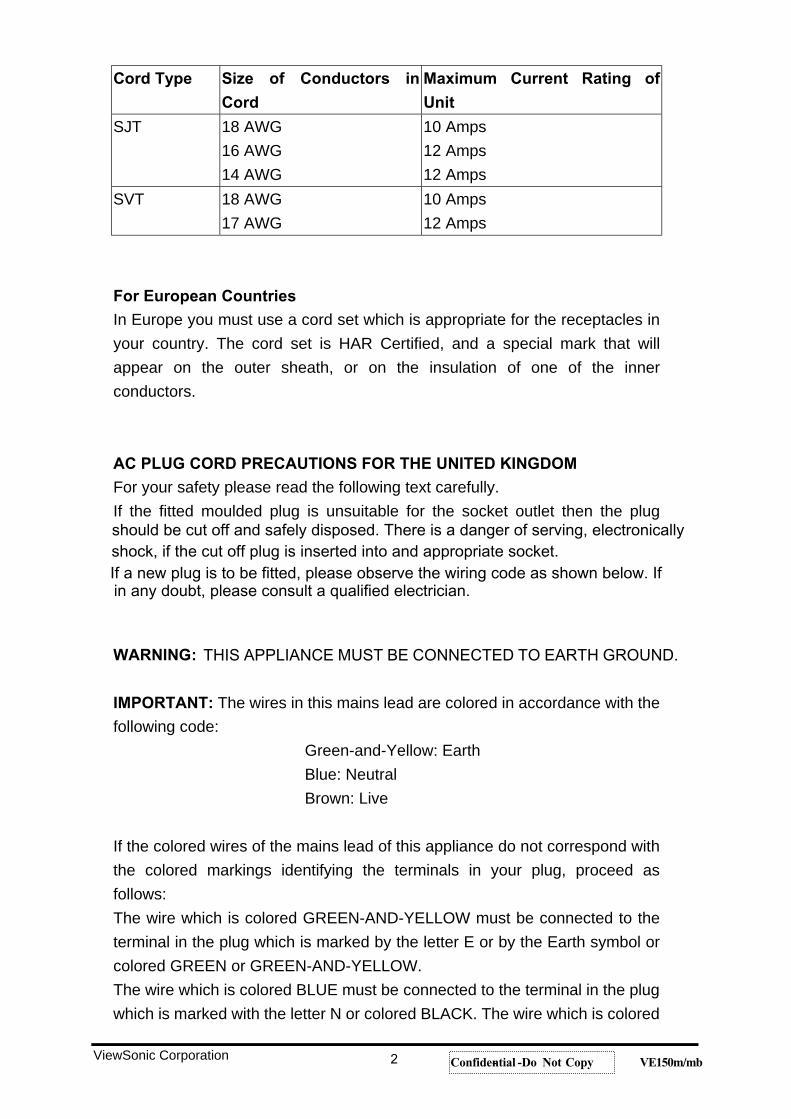
Cord Type Size of Conductors in
Cord
Maximum Current Rating of
Unit
SJT 18 AWG 16 AWG 14 AWG
10 Amps 12 Amps 12 Amps
SVT 18 AWG 17 AWG
10 Amps 12 Amps
For European Countries In Europe you must use a cord set which is appropriate for the receptacles in your country. The cord set is HAR Certified, and a special mark that will appear on the outer sheath, or on the insulation of one of the inner conductors.
AC PLUG CORD PRECAUTIONS FOR THE UNITED KINGDOM For your safety please read the following text carefully. If the fitted moulded plug is unsuitable for the socket outlet then the plug
WARNING:
IMPORTANT: The wires in this mains lead are colored in accordance with the following code:
Green-and-Yellow: Earth Blue: Neutral Brown: Live
If the colored wires of the mains lead of this appliance do not correspond with the colored markings identifying the terminals in your plug, proceed as follows:The wire which is colored GREEN-AND-YELLOW must be connected to the terminal in the plug which is marked by the letter E or by the Earth symbol or colored GREEN or GREEN-AND-YELLOW. The wire which is colored BLUE must be connected to the terminal in the plug which is marked with the letter N or colored BLACK. The wire which is colored
ViewSonic Corporation 2 Confidential -- Do Not Copy VE150m/mb
should be cut off and safely disposed. There is a danger of serving, electronically
THIS APPLIANCE MUST BE CONNECTED TO EARTH GROUND.
shock, if the cut off plug is inserted into and appropriate socket. If a new plug is to be fitted, please observe the wiring code as shown below. If in any doubt, please consult a qualified electrician.
BROWN must be connected to the terminal in the plug which is marked with the letter L or colored RED. If you have any questions concerning which proper power cord to use, please consult with the dealer from whom you have purchased the product.
PRECAUTIONFor best viewing conditions sit at least 18" from the LCD Display.
AVOID TOUCHING THE SCREEN WITH YOUR FINGERS. Oils from the skin are difficult to remove.
NEVER REMOVE THE REAR COVER. The LCD Display containshigh-voltage parts. You may suffer serious injury if you touch these parts.
Avoid exposing the LCD Display to direct sunlight or another heat source. The ViewPanel should be facing away from direct sunlight to reduce glare.
Always handle your LCD Display with care when moving it.
Place your LCD Display in a well-ventilated area. Do not place anything on the ViewPanel that prevents adequate dissipation of heat.
Ensure the area around the LCD Display is clean and free of moisture.
Do not place heavy objects on the LCD Display, video cable, or power cord.
If smoke, abnormal noise, or strange odor is present, immediately switch the LCD Display off and call your dealer or ViewSonic. It is dangerousto continue using the LCD Display.
Chapter 1 PREFACEThe purpose of this manual provides integral information you need to
maintain the LCD Monitor. And this manual is applied to the mode of 1024 x 768 pixels color TFT LCD Monitor. This manual is for the experienced electronic technicians and those with similar backgrounds. Send the products back to the local distributor or repair center. Do not attempt any disassembling actions that are complex or aren’t mentioned in the troubleshooting chapter.
ViewSonic Corporation 3 Confidential -- Do Not Copy VE150m/mb
The manual includes Engineering Specification, Front Panel
Control description, Circuit Description, Troubleshooting, Theory of
Operation, Mechanical Assembly, Service Parts List, and Circuit
Diagram. Each section will be briefly discussed below.
ENGINEERING SPECIFICATIONSThis CHAPTER provides the engineering specification for the
designated Display. Since we only provide a reference engineering specification in this service manual, Please refer to ViewSonic Engineering ProductSpecification for detailed product specification.
FRONT PANEL CONTROLThis CHAPTER provides User Control Panel functions and descriptions.
Access to OSD (On Screen Display) setting, (eg. timing adjustment, defaultsetting, restoring to factory mode can be referenced in this CHAPTER.
CIRCUIT DESCRIPTIONSThe first part of this CHAPTER provides a functional block diagram
for the Display. The second part of this CHAPTER consists of a detailed I/O connector PIN ASSIGNMENT for the PCBs.
TROUBLESHOOTINGMaintenance procedures described in this chapter are intended to
isolate faulty parts and replace them in the field. The chapter makes explanations on how to detect errors, through a series of sequential flow chart for fault detection and means of corrections. The material contained in this chapter provides basic troubleshooting techniques on the module level.
THEORY OF OPERATIONThis chapter is written and designed for use on in-lab
troubleshooting. The chapter contains the detailed description on the operations of parts, which are labeled on the Functional Block Diagram. The chapter is intended for in-lab repair personnel who would conduct an in-lab troubleshooting of the system.
MECHANICAL ASSEMBLYThis chapter contains an Exploded Drawing for the system, for which
can be used by the repair personnel for parts identity.
ViewSonic Corporation 4 Confidential -- Do Not Copy VE150m/mb
This chapter aims to serve as a guide in procuring replacement parts for this product.
CIRCUIT DIAGRAM
ViewSonic Corporation 5 Confidential -- Do Not Copy VE150m/mb
SERVICE PARTS LIST
PCB LAYOUT
This CHAPTER provides functional circuits diagram of the LCD Display.
This CHAPTER provides PCB Layout of the LCD Display.
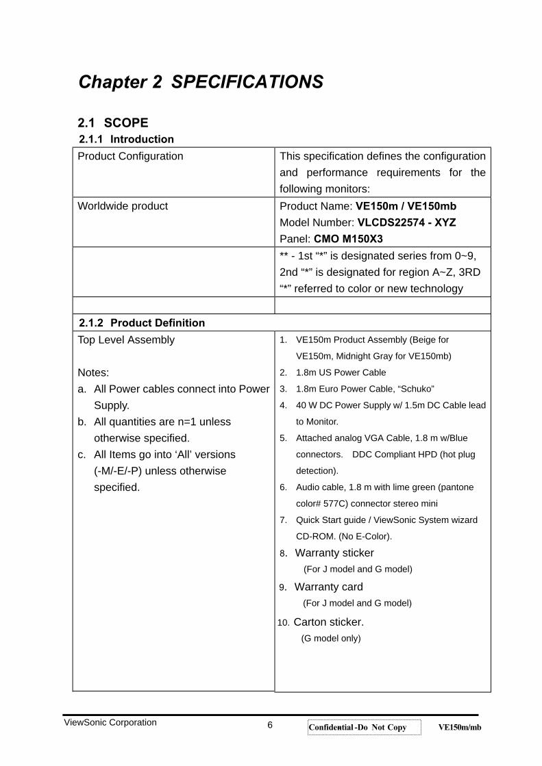
Chapter 2 SPECIFICATIONS
2.1 SCOPE 2.1.1 Introduction
Product Configuration This specification defines the configuration and performance requirements for the following monitors:
Worldwide product Product Name: VE150m / VE150mb
Model Number: VLCDS22574 - XYZ
Panel: CMO M150X3
** - 1st “*” is designated series from 0~9, 2nd “*” is designated for region A~Z, 3RD “*” referred to color or new technology
2.1.2 Product Definition
Top Level Assembly
Notes:a. All Power cables connect into Power
Supply. b. All quantities are n=1 unless
otherwise specified. c. All Items go into ‘All’ versions
(-M/-E/-P) unless otherwise specified.
1. VE150m Product Assembly (Beige for VE150m, Midnight Gray for VE150mb)
2. 1.8m US Power Cable 3. 1.8m Euro Power Cable, “Schuko” 4. 40 W DC Power Supply w/ 1.5m DC Cable lead
to Monitor. 5. Attached analog VGA Cable, 1.8 m w/Blue
connectors. DDC Compliant HPD (hot plug detection).
6. Audio cable, 1.8 m with lime green (pantone color# 577C) connector stereo mini
7. Quick Start guide / ViewSonic System wizardCD-ROM. (No E-Color).
8. Warranty sticker(For J model and G model)
9. Warranty card(For J model and G model)
10. Carton sticker. (G model only)
ViewSonic Corporation 6 Confidential -- Do Not Copy VE150m/mb
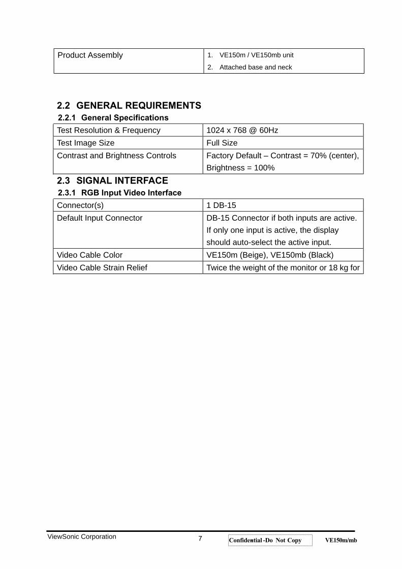
Product Assembly 1. VE150m / VE150mb unit 2. Attached base and neck
2.2 GENERAL REQUIREMENTS 2.2.1 General Specifications
Test Resolution & Frequency 1024 x 768 @ 60Hz Test Image Size Full Size Contrast and Brightness Controls Factory Default – Contrast = 70% (center),
Brightness = 100% 2.3 SIGNAL INTERFACE 2.3.1 RGB Input Video Interface
Connector(s) 1 DB-15Default Input Connector DB-15 Connector if both inputs are active.
If only one input is active, the display should auto-select the active input.
Video Cable Color VE150m (Beige), VE150mb (Black) Video Cable Strain Relief Twice the weight of the monitor or 18 kg for
ViewSonic Corporation 7 Confidential -- Do Not Copy VE150m/mb
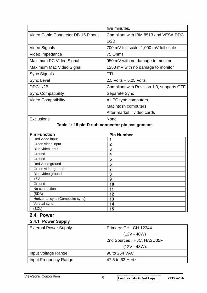
five minutes. Video Cable Connector DB-15 Pinout Compliant with IBM 8513 and VESA DDC
1/2B.Video Signals 700 mV full scale, 1,000 mV full scale Video Impedance 75 Ohms Maximum PC Video Signal 950 mV with no damage to monitor Maximum Mac Video Signal 1250 mV with no damage to monitor Sync Signals TTL Sync Level 2.5 Volts – 5.25 Volts DDC 1/2B Compliant with Revision 1.3, supports GTF Sync Compatibility Separate Sync Video Compatibility All PC type computers
Macintosh computers After market video cards
Exclusions None Table 1: 15 pin D-sub connector pin assignment
Pin Number Pin Function Red video input 1Green video input 2Blue video input 3Ground 4Ground 5Red video ground 6Green video ground 7Blue video ground 8+5V 9Ground 10No connection 11 (SDA) 12Horizontal sync (Composite sync) 13Vertical sync 14(SCL) 15
2.4 Power 2.4.1 Power Supply
External Power Supply Primary: CHI, CH-1234X (12V - 40W)
2nd Sources : HJC, HASU05F (12V - 48W).
Input Voltage Range 90 to 264 VAC Input Frequency Range 47.5 to 63 Hertz
ViewSonic Corporation 8 Confidential -- Do Not Copy VE150m/mb
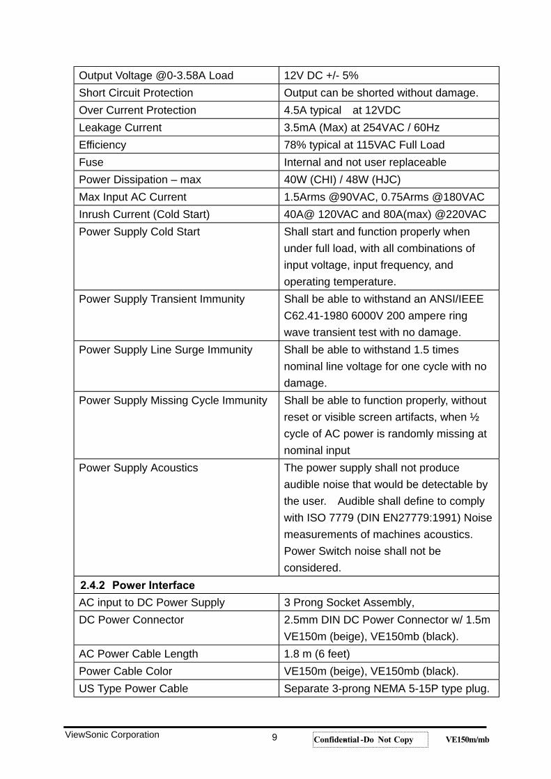
Output Voltage @0-3.58A Load 12V DC +/- 5% Short Circuit Protection Output can be shorted without damage. Over Current Protection 4.5A typical at 12VDC Leakage Current 3.5mA (Max) at 254VAC / 60Hz Efficiency 78% typical at 115VAC Full Load Fuse Internal and not user replaceable Power Dissipation – max 40W (CHI) / 48W (HJC) Max Input AC Current 1.5Arms @90VAC, 0.75Arms @180VAC Inrush Current (Cold Start) 40A@ 120VAC and 80A(max) @220VAC Power Supply Cold Start Shall start and function properly when
under full load, with all combinations of input voltage, input frequency, and operating temperature.
Power Supply Transient Immunity Shall be able to withstand an ANSI/IEEE C62.41-1980 6000V 200 ampere ring wave transient test with no damage.
Power Supply Line Surge Immunity Shall be able to withstand 1.5 times nominal line voltage for one cycle with no damage.
Power Supply Missing Cycle Immunity Shall be able to function properly, without reset or visible screen artifacts, when ½ cycle of AC power is randomly missing at nominal input
Power Supply Acoustics The power supply shall not produce audible noise that would be detectable by the user. Audible shall define to comply with ISO 7779 (DIN EN27779:1991) Noise measurements of machines acoustics. Power Switch noise shall not be considered.
2.4.2 Power Interface
AC input to DC Power Supply 3 Prong Socket Assembly, DC Power Connector 2.5mm DIN DC Power Connector w/ 1.5m
VE150m (beige), VE150mb (black). AC Power Cable Length 1.8 m (6 feet) Power Cable Color VE150m (beige), VE150mb (black). US Type Power Cable Separate 3-prong NEMA 5-15P type plug.
ViewSonic Corporation 9 Confidential -- Do Not Copy VE150m/mb
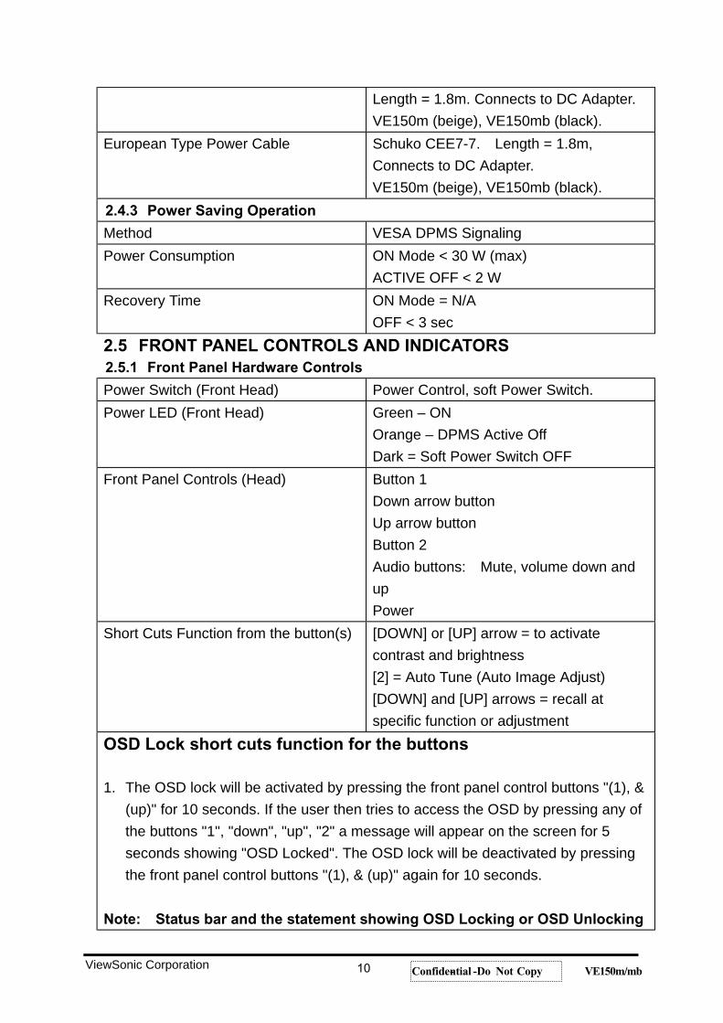
Length = 1.8m. Connects to DC Adapter. VE150m (beige), VE150mb (black).
European Type Power Cable Schuko CEE7-7. Length = 1.8m, Connects to DC Adapter. VE150m (beige), VE150mb (black).
2.4.3 Power Saving Operation
Method VESA DPMS Signaling Power Consumption ON Mode < 30 W (max)
ACTIVE OFF < 2 WRecovery Time ON Mode = N/A
OFF < 3 sec 2.5 FRONT PANEL CONTROLS AND INDICATORS 2.5.1 Front Panel Hardware Controls
Power Switch (Front Head) Power Control, soft Power Switch. Power LED (Front Head) Green – ON
Orange – DPMS Active Off Dark = Soft Power Switch OFF
Front Panel Controls (Head) Button 1 Down arrow button Up arrow button Button 2 Audio buttons: Mute, volume down and upPower
Short Cuts Function from the button(s) [DOWN] or [UP] arrow = to activate contrast and brightness [2] = Auto Tune (Auto Image Adjust) [DOWN] and [UP] arrows = recall at specific function or adjustment
OSD Lock short cuts function for the buttons
1. The OSD lock will be activated by pressing the front panel control buttons "(1), & (up)" for 10 seconds. If the user then tries to access the OSD by pressing any of the buttons "1", "down", "up", "2" a message will appear on the screen for 5 seconds showing "OSD Locked". The OSD lock will be deactivated by pressing the front panel control buttons "(1), & (up)" again for 10 seconds.
Note: Status bar and the statement showing OSD Locking or OSD Unlocking
ViewSonic Corporation 10 Confidential -- Do Not Copy VE150m/mb
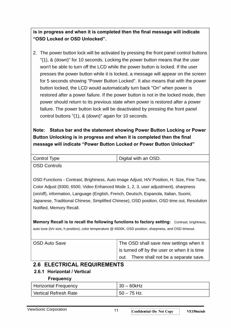
is in progress and when it is completed then the final message will indicate
“OSD Locked or OSD Unlocked”.
2. The power button lock will be activated by pressing the front panel control buttons "(1), & (down)" for 10 seconds. Locking the power button means that the user won't be able to turn off the LCD while the power button is locked. If the user presses the power button while it is locked, a message will appear on the screen for 5 seconds showing "Power Button Locked". It also means that with the power button locked, the LCD would automatically turn back "On" when power is restored after a power failure. If the power button is not in the locked mode, then power should return to its previous state when power is restored after a power failure. The power button lock will be deactivated by pressing the front panel control buttons "(1), & (down)" again for 10 seconds.
Note: Status bar and the statement showing Power Button Locking or Power
Button Unlocking is in progress and when it is completed then the final
message will indicate “Power Button Locked or Power Button Unlocked”
Control Type Digital with an OSD. OSD Controls
OSD Functions - Contrast, Brightness, Auto Image Adjust, H/V Position, H. Size, Fine Tune, Color Adjust (9300, 6500, Video Enhanced Mode 1, 2, 3, user adjustment), sharpness (on/off), information, Language (English, French, Deutsch, Espanola, Italian, Suomi, Japanese, Traditional Chinese, Simplified Chinese), OSD position, OSD time out, Resolution Notified, Memory Recall.
Memory Recall is to recall the following functions to factory setting: Contrast, brightness,
auto tune (h/v size, h position), color temperature @ 6500K, OSD position, sharpness, and OSD timeout.
OSD Auto Save The OSD shall save new settings when it is turned off by the user or when it is time out. There shall not be a separate save.
2.6 ELECTRICAL REQUIREMENTS 2.6.1 Horizontal / Vertical
Frequency
Horizontal Frequency 30 – 60kHz Vertical Refresh Rate 50 – 75 Hz.
ViewSonic Corporation 11 Confidential -- Do Not Copy VE150m/mb
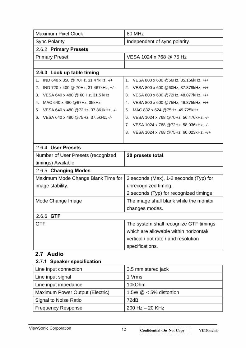
Maximum Pixel Clock 80 MHz Sync Polarity Independent of sync polarity.2.6.2 Primary Presets
Primary Preset VESA 1024 x 768 @ 75 Hz
2.6.3 Look up table timing 1. IND 640 x 350 @ 70Hz, 31.47kHz, -/+ 2. IND 720 x 400 @ 70Hz, 31.467kHz, +/- 3. VESA 640 x 480 @ 60 Hz, 31.5 kHz 4. MAC 640 x 480 @67Hz, 35kHz 5. VESA 640 x 480 @72Hz, 37.861kHz, -/- 6. VESA 640 x 480 @75Hz, 37.5kHz, -/-
1. VESA 800 x 600 @56Hz, 35.156kHz, +/+ 2. VESA 800 x 600 @60Hz, 37.879kHz, +/+ 3. VESA 800 x 600 @72Hz, 48.077kHz, +/+ 4. VESA 800 x 600 @75Hz, 46.875kHz, +/+ 5. MAC 832 x 624 @75Hz, 49.725kHz 6. VESA 1024 x 768 @70Hz, 56.476kHz, -/- 7. VESA 1024 x 768 @72Hz, 58.036kHz, -/- 8. VESA 1024 x 768 @75Hz, 60.023kHz, +/+
2.6.4 User Presets
Number of User Presets (recognized timings) Available
20 presets total.
2.6.5 Changing Modes
Maximum Mode Change Blank Time for image stability.
3 seconds (Max), 1-2 seconds (Typ) for unrecognized timing. 2 seconds (Typ) for recognized timings
Mode Change Image The image shall blank while the monitor changes modes.
2.6.6 GTF
GTF The system shall recognize GTF timings which are allowable within horizontal/ vertical / dot rate / and resolution specifications.
2.7 Audio 2.7.1 Speaker specification
Line input connection 3.5 mm stereo jack Line input signal 1 Vrms Line input impedance 10kOhm Maximum Power Output (Electric) 1.5W @ < 5% distortion Signal to Noise Ratio 72dB Frequency Response 200 Hz – 20 KHz
ViewSonic Corporation 12 Confidential -- Do Not Copy VE150m/mb
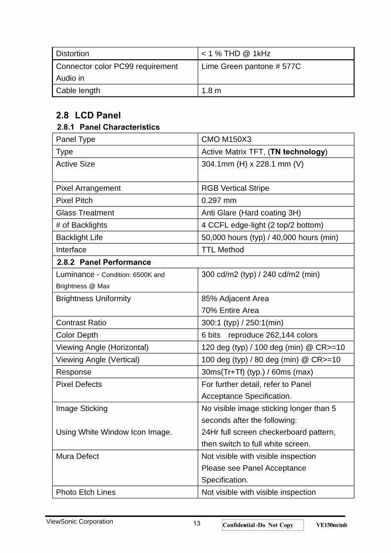
Distortion < 1 % THD @ 1kHz Connector color PC99 requirement Audio in
Lime Green pantone # 577C
Cable length 1.8 m
2.8 LCD Panel 2.8.1 Panel Characteristics
Panel Type CMO M150X3 Type Active Matrix TFT, (TN technology)Active Size 304.1mm (H) x 228.1 mm (V)
Pixel Arrangement RGB Vertical Stripe Pixel Pitch 0.297 mm Glass Treatment Anti Glare (Hard coating 3H) # of Backlights 4 CCFL edge-light (2 top/2 bottom) Backlight Life 50,000 hours (typ) / 40,000 hours (min) Interface TTL Method 2.8.2 Panel Performance
Luminance - Condition: 6500K and Brightness @ Max
300 cd/m2 (typ) / 240 cd/m2 (min)
Brightness Uniformity 85% Adjacent Area 70% Entire Area
Contrast Ratio 300:1 (typ) / 250:1(min) Color Depth 6 bits reproduce 262,144 colors Viewing Angle (Horizontal) 120 deg (typ) / 100 deg (min) @ CR>=10 Viewing Angle (Vertical) 100 deg (typ) / 80 deg (min) @ CR>=10 Response 30ms(Tr+Tf) (typ.) / 60ms (max) Pixel Defects For further detail, refer to Panel
Acceptance Specification. Image Sticking
Using White Window Icon Image.
No visible image sticking longer than 5 seconds after the following: 24Hr full screen checkerboard pattern, then switch to full white screen.
Mura Defect Not visible with visible inspectionPlease see Panel Acceptance Specification.
Photo Etch Lines Not visible with visible inspection
ViewSonic Corporation 13 Confidential -- Do Not Copy VE150m/mb
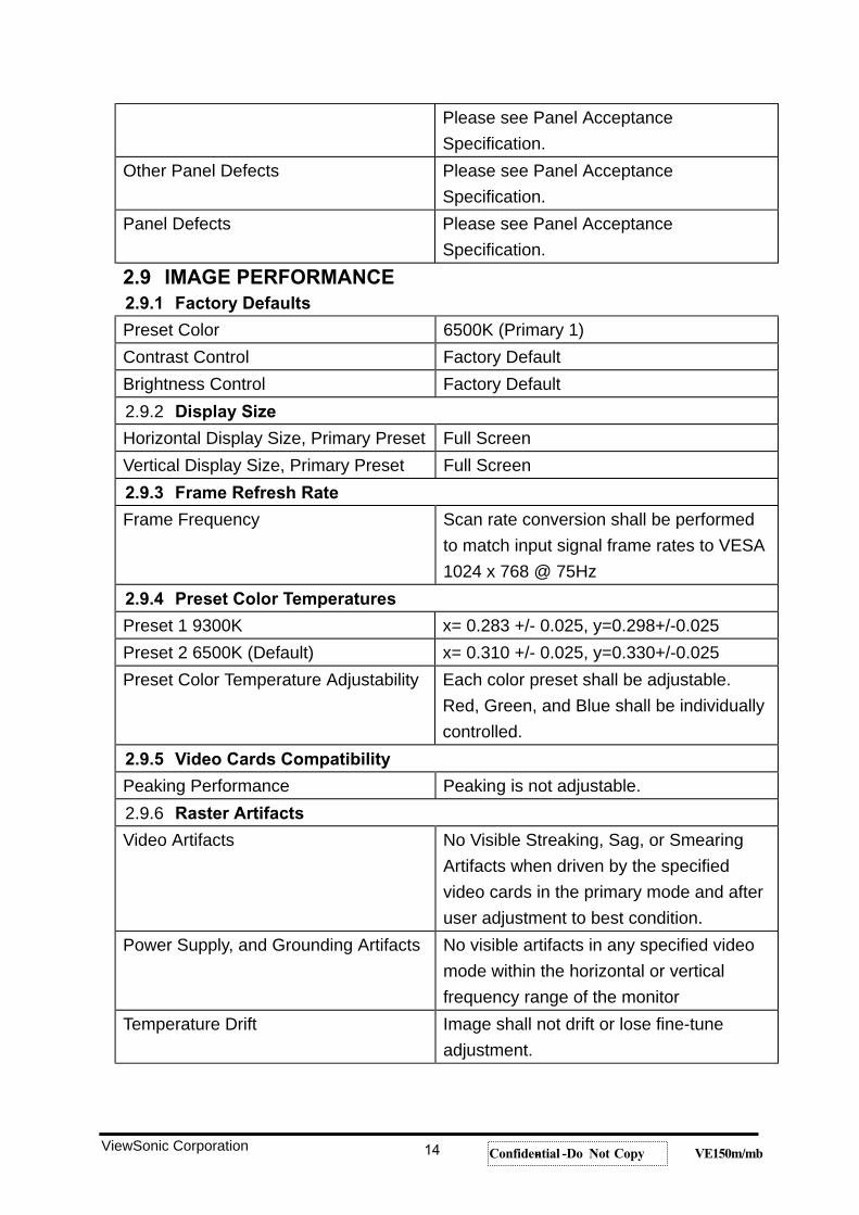
Please see Panel Acceptance Specification.
Other Panel Defects Please see Panel Acceptance Specification.
Panel Defects Please see Panel Acceptance Specification.
2.9 IMAGE PERFORMANCE 2.9.1 Factory Defaults
Preset Color 6500K (Primary 1) Contrast Control Factory DefaultBrightness Control Factory Default2.9.2 Display Size
Horizontal Display Size, Primary Preset Full Screen Vertical Display Size, Primary Preset Full Screen 2.9.3 Frame Refresh Rate
Frame Frequency Scan rate conversion shall be performed to match input signal frame rates to VESA 1024 x 768 @ 75Hz
2.9.4 Preset Color Temperatures
Preset 1 9300K x= 0.283 +/- 0.025, y=0.298+/-0.025 Preset 2 6500K (Default) x= 0.310 +/- 0.025, y=0.330+/-0.025 Preset Color Temperature Adjustability Each color preset shall be adjustable.
Red, Green, and Blue shall be individually controlled.
2.9.5 Video Cards Compatibility
Peaking Performance Peaking is not adjustable. 2.9.6 Raster Artifacts
Video Artifacts No Visible Streaking, Sag, or Smearing Artifacts when driven by the specified video cards in the primary mode and after user adjustment to best condition.
Power Supply, and Grounding Artifacts No visible artifacts in any specified video mode within the horizontal or vertical frequency range of the monitor
Temperature Drift Image shall not drift or lose fine-tune adjustment.
ViewSonic Corporation 14 Confidential -- Do Not Copy VE150m/mb
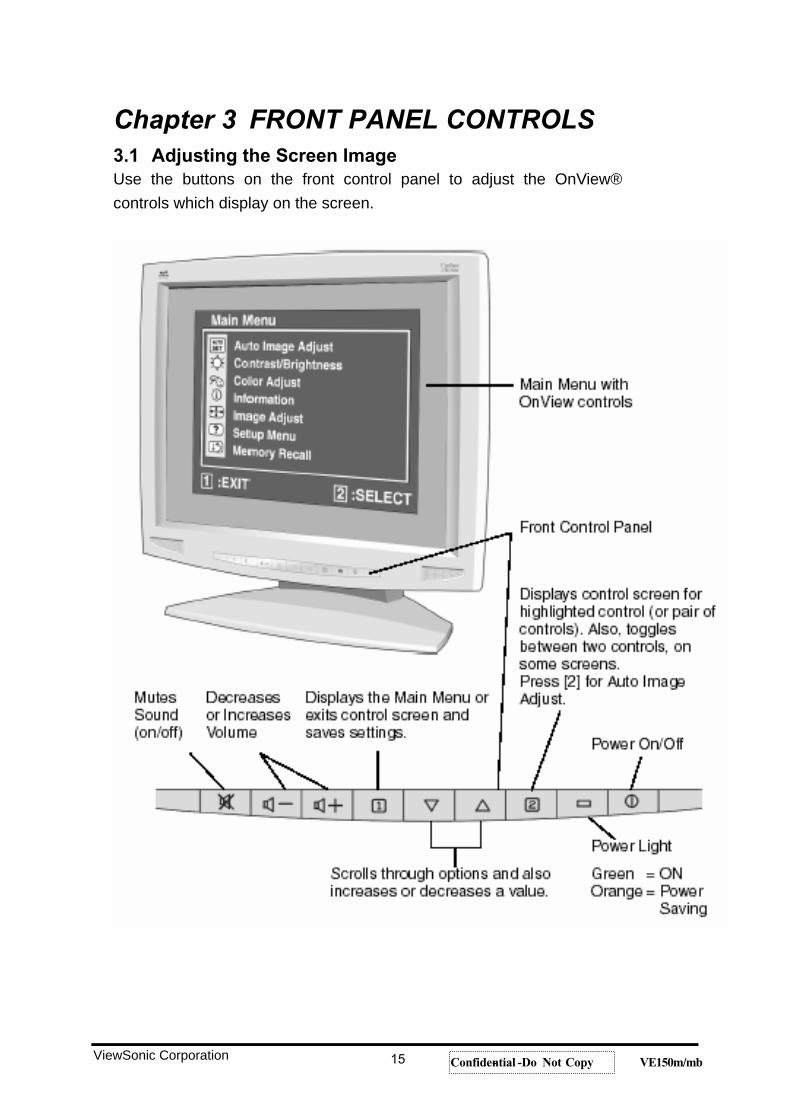
Chapter 3 FRONT PANEL CONTROLS 3.1 Adjusting the Screen Image Use the buttons on the front control panel to adjust the OnView® controls which display on the screen.
ViewSonic Corporation 15 Confidential -- Do Not Copy VE150m/mb
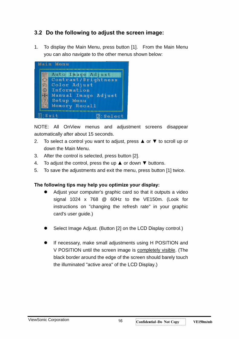
3.2 Do the following to adjust the screen image:
1. To display the Main Menu, press button [1]. From the Main Menu you can also navigate to the other menus shown below:
NOTE: All OnView menus and adjustment screens disappear automatically after about 15 seconds. 2. To select a control you want to adjust, press or to scroll up or
down the Main Menu. 3. After the control is selected, press button [2]. 4. To adjust the control, press the up or down buttons. 5. To save the adjustments and exit the menu, press button [1] twice.
The following tips may help you optimize your display: Adjust your computer's graphic card so that it outputs a video
signal 1024 x 768 @ 60Hz to the VE150m. (Look for instructions on "changing the refresh rate" in your graphic card's user guide.)
Select Image Adjust. (Button [2] on the LCD Display control.)
If necessary, make small adjustments using H POSITION and V POSITION until the screen image is completely visible. (The black border around the edge of the screen should barely touch the illuminated "active area" of the LCD Display.)
ViewSonic Corporation 16 Confidential -- Do Not Copy VE150m/mb
3.3 Main Menu Controls
The menu items shown below can be adjusted by using the up and down buttons on the front of the LCD Display.
Control Explanation
Auto Image Adjust automatically sizes, centers, auto-contrasts and fine-tunes the video signal to eliminate waviness and distortion. Press the [2] button to obtain a sharper image. NOTE: Auto tune works with most common video cards. If this function does not work on your LCD Display, then lower the video refresh rate to 60 Hz and set the resolution to its preset value.
Contrast/Brightness Contrast adjusts the difference between the image background (black level) and the foreground (white level). Brightness adjusts background black level of the screen image. Press button [2] to toggle between Contrast and Brightness.
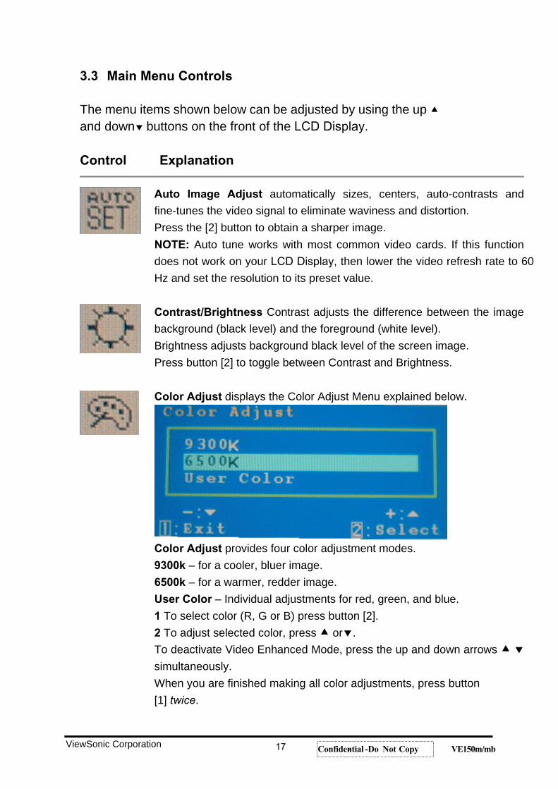
Color Adjust displays the Color Adjust Menu explained below.
Color Adjust provides four color adjustment modes. 9300k – for a cooler, bluer image. 6500k – for a warmer, redder image. User Color – Individual adjustments for red, green, and blue. 1 To select color (R, G or B) press button [2]. 2 To adjust selected color, press or .To deactivate Video Enhanced Mode, press the up and down arrows simultaneously.When you are finished making all color adjustments, press button [1] twice.
ViewSonic Corporation 17 Confidential -- Do Not Copy VE150m/mb
Control Explanation
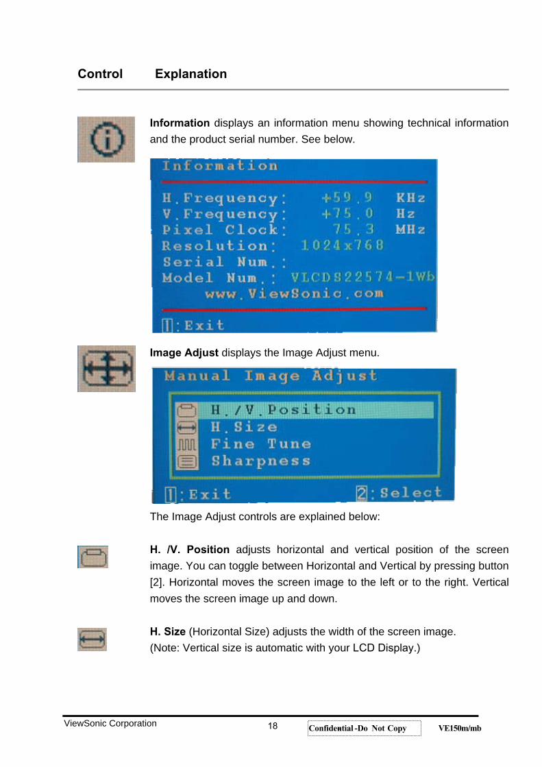
Information displays an information menu showing technical information and the product serial number. See below.
Image Adjust displays the Image Adjust menu.
The Image Adjust controls are explained below:
H. /V. Position adjusts horizontal and vertical position of the screen image. You can toggle between Horizontal and Vertical by pressing button [2]. Horizontal moves the screen image to the left or to the right. Vertical moves the screen image up and down.
H. Size (Horizontal Size) adjusts the width of the screen image. (Note: Vertical size is automatic with your LCD Display.)
ViewSonic Corporation 18 Confidential -- Do Not Copy VE150m/mb
Control Explanation
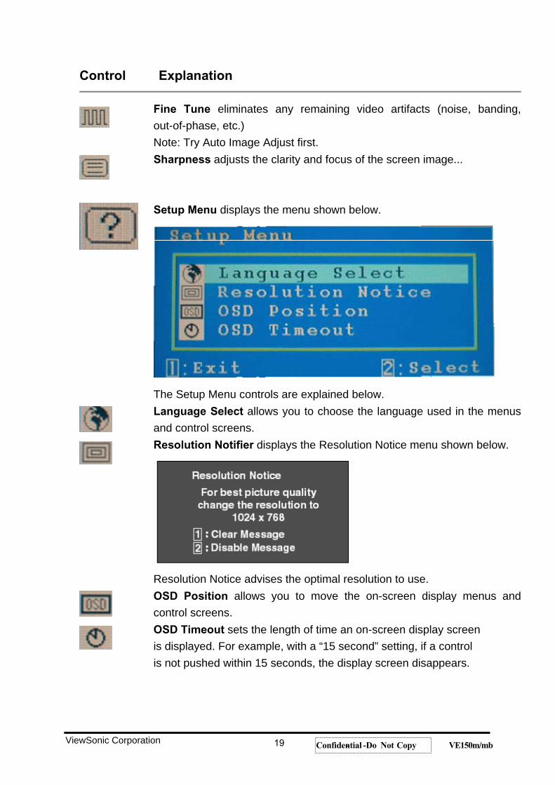
Fine Tune eliminates any remaining video artifacts (noise, banding, out-of-phase, etc.) Note: Try Auto Image Adjust first. Sharpness adjusts the clarity and focus of the screen image...
Setup Menu displays the menu shown below.
The Setup Menu controls are explained below. Language Select allows you to choose the language used in the menus and control screens. Resolution Notifier displays the Resolution Notice menu shown below.
Resolution Notice advises the optimal resolution to use. OSD Position allows you to move the on-screen display menus and control screens. OSD Timeout sets the length of time an on-screen display screen is displayed. For example, with a “15 second” setting, if a control is not pushed within 15 seconds, the display screen disappears.
ViewSonic Corporation 19 Confidential -- Do Not Copy VE150m/mb
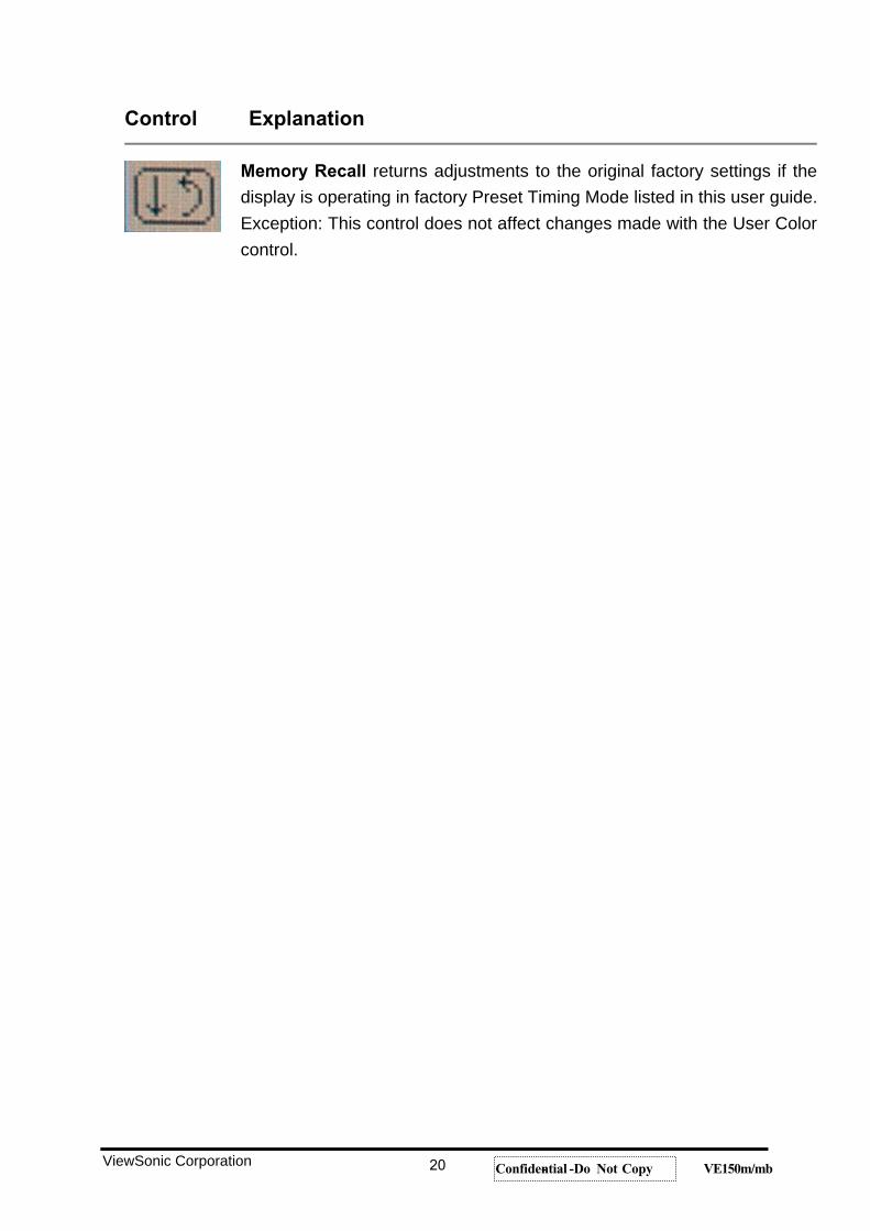
Control Explanation
Memory Recall returns adjustments to the original factory settings if the display is operating in factory Preset Timing Mode listed in this user guide. Exception: This control does not affect changes made with the User Color control.
ViewSonic Corporation 20 Confidential -- Do Not Copy VE150m/mb
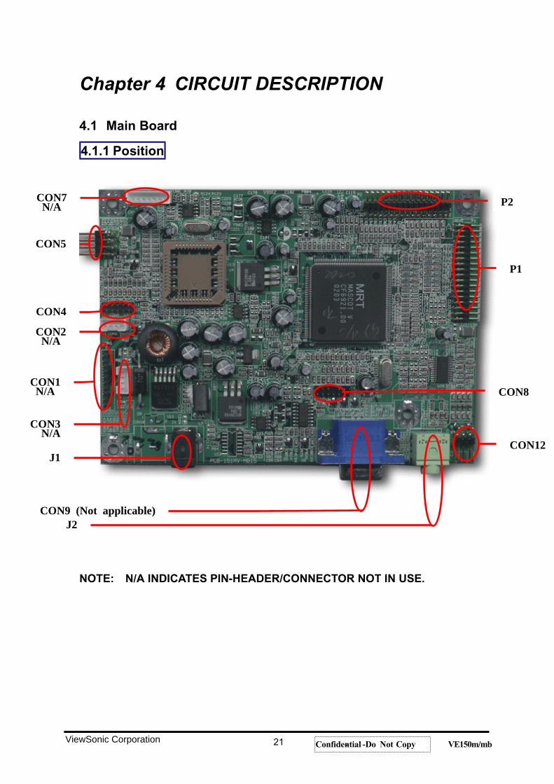
Chapter 4 CIRCUIT DESCRIPTION
4.1 Main Board
4.1.1 Position
NOTE: N/A INDICATES PIN-HEADER/CONNECTOR NOT IN USE.
P2
CON5
P1
CON12
CON7N/A
CON4
CON3N/A
CON1N/A
J1
CON9 (Not applicable)J2
CON2N/A
CON8
ViewSonic Corporation 21 Confidential -- Do Not Copy VE150m/mb
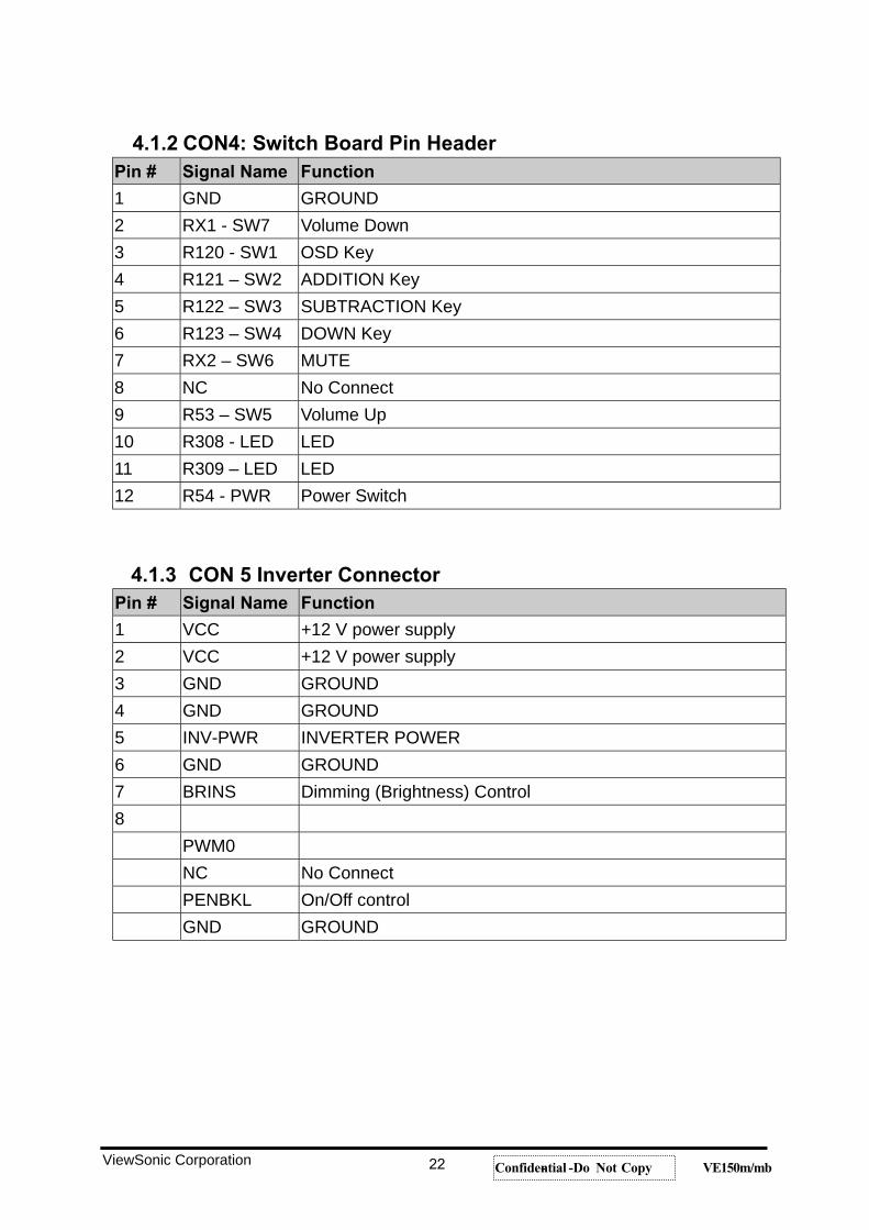
4.1.2 CON4: Switch Board Pin HeaderPin # Signal Name Function
1 GND GROUND 2 RX1 - SW7 Volume Down 3 R120 - SW1 OSD Key 4 R121 – SW2 ADDITION Key 5 R122 – SW3 SUBTRACTION Key 6 R123 – SW4 DOWN Key 7 RX2 – SW6 MUTE 8 NC No Connect 9 R53 – SW5 Volume Up 10 R308 - LED LED 11 R309 – LED LED 12 R54 - PWR Power Switch
4.1.3 CON 5 Inverter ConnectorPin # Signal Name Function
1 VCC +12 V power supply 2 VCC +12 V power supply 3 GND GROUND 4 GND GROUND 5 INV-PWR INVERTER POWER 6 GND GROUND 7 BRINS Dimming (Brightness) Control 8 PWM0 NC No Connect PENBKL On/Off control GND GROUND
ViewSonic Corporation 22 Confidential -- Do Not Copy VE150m/mb
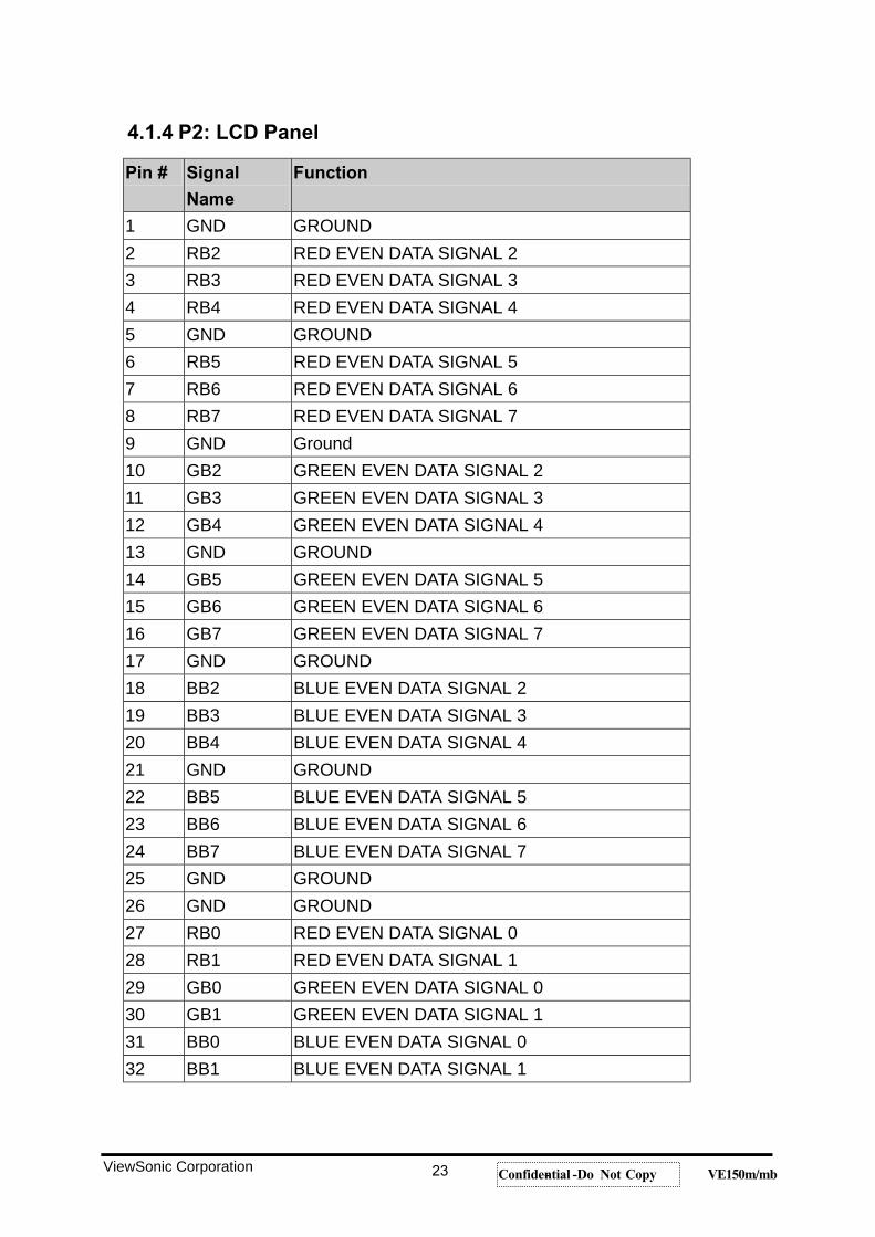
4.1.4 P2: LCD Panel
Pin # Signal
Name
Function
1 GND GROUND 2 RB2 RED EVEN DATA SIGNAL 2 3 RB3 RED EVEN DATA SIGNAL 3 4 RB4 RED EVEN DATA SIGNAL 4 5 GND GROUND 6 RB5 RED EVEN DATA SIGNAL 5 7 RB6 RED EVEN DATA SIGNAL 6 8 RB7 RED EVEN DATA SIGNAL 7 9 GND Ground 10 GB2 GREEN EVEN DATA SIGNAL 2 11 GB3 GREEN EVEN DATA SIGNAL 3 12 GB4 GREEN EVEN DATA SIGNAL 4 13 GND GROUND 14 GB5 GREEN EVEN DATA SIGNAL 5 15 GB6 GREEN EVEN DATA SIGNAL 6 16 GB7 GREEN EVEN DATA SIGNAL 7 17 GND GROUND 18 BB2 BLUE EVEN DATA SIGNAL 2 19 BB3 BLUE EVEN DATA SIGNAL 3 20 BB4 BLUE EVEN DATA SIGNAL 4 21 GND GROUND 22 BB5 BLUE EVEN DATA SIGNAL 5 23 BB6 BLUE EVEN DATA SIGNAL 6 24 BB7 BLUE EVEN DATA SIGNAL 7 25 GND GROUND 26 GND GROUND 27 RB0 RED EVEN DATA SIGNAL 0 28 RB1 RED EVEN DATA SIGNAL 1 29 GB0 GREEN EVEN DATA SIGNAL 0 30 GB1 GREEN EVEN DATA SIGNAL 1 31 BB0 BLUE EVEN DATA SIGNAL 0 32 BB1 BLUE EVEN DATA SIGNAL 1
ViewSonic Corporation 23 Confidential -- Do Not Copy VE150m/mb
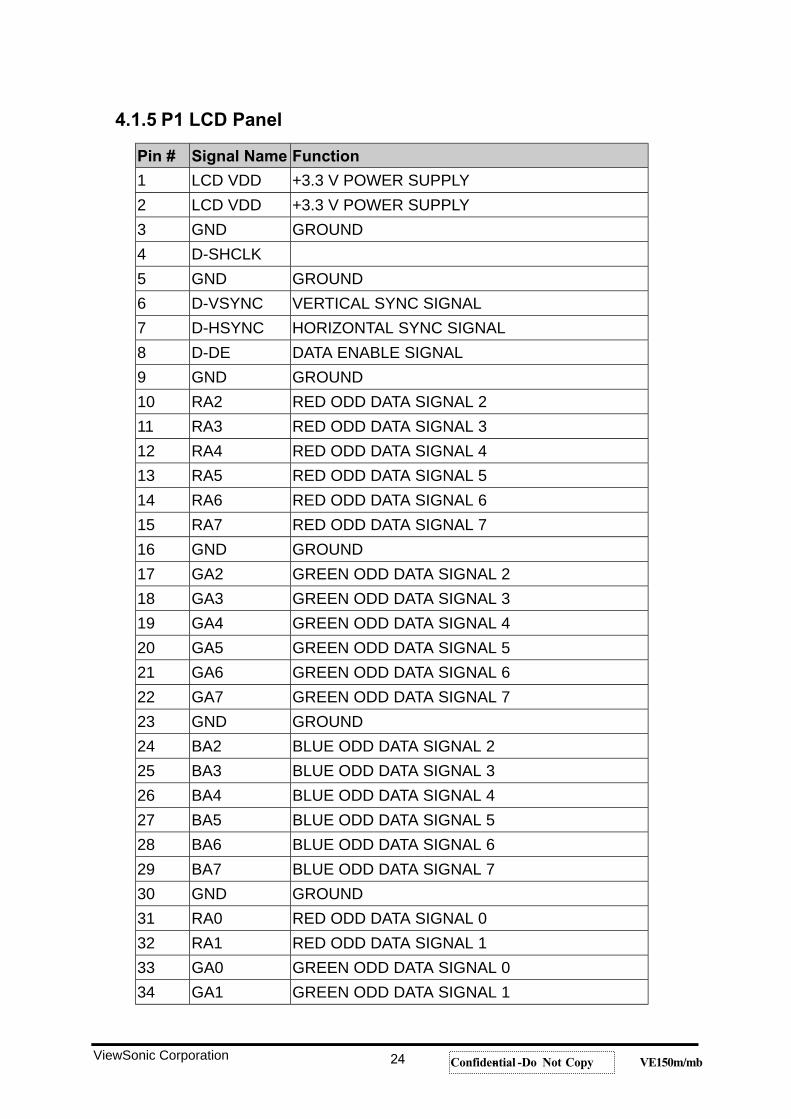
4.1.5 P1 LCD Panel
Pin # Signal Name Function
1 LCD VDD +3.3 V POWER SUPPLY 2 LCD VDD +3.3 V POWER SUPPLY 3 GND GROUND 4 D-SHCLK 5 GND GROUND 6 D-VSYNC VERTICAL SYNC SIGNAL 7 D-HSYNC HORIZONTAL SYNC SIGNAL 8 D-DE DATA ENABLE SIGNAL 9 GND GROUND 10 RA2 RED ODD DATA SIGNAL 2 11 RA3 RED ODD DATA SIGNAL 3 12 RA4 RED ODD DATA SIGNAL 4 13 RA5 RED ODD DATA SIGNAL 5 14 RA6 RED ODD DATA SIGNAL 6 15 RA7 RED ODD DATA SIGNAL 7 16 GND GROUND 17 GA2 GREEN ODD DATA SIGNAL 2 18 GA3 GREEN ODD DATA SIGNAL 3 19 GA4 GREEN ODD DATA SIGNAL 4 20 GA5 GREEN ODD DATA SIGNAL 5 21 GA6 GREEN ODD DATA SIGNAL 6 22 GA7 GREEN ODD DATA SIGNAL 7 23 GND GROUND 24 BA2 BLUE ODD DATA SIGNAL 2 25 BA3 BLUE ODD DATA SIGNAL 3 26 BA4 BLUE ODD DATA SIGNAL 4 27 BA5 BLUE ODD DATA SIGNAL 5 28 BA6 BLUE ODD DATA SIGNAL 6 29 BA7 BLUE ODD DATA SIGNAL 7 30 GND GROUND 31 RA0 RED ODD DATA SIGNAL 0 32 RA1 RED ODD DATA SIGNAL 1 33 GA0 GREEN ODD DATA SIGNAL 0 34 GA1 GREEN ODD DATA SIGNAL 1
ViewSonic Corporation 24 Confidential -- Do Not Copy VE150m/mb
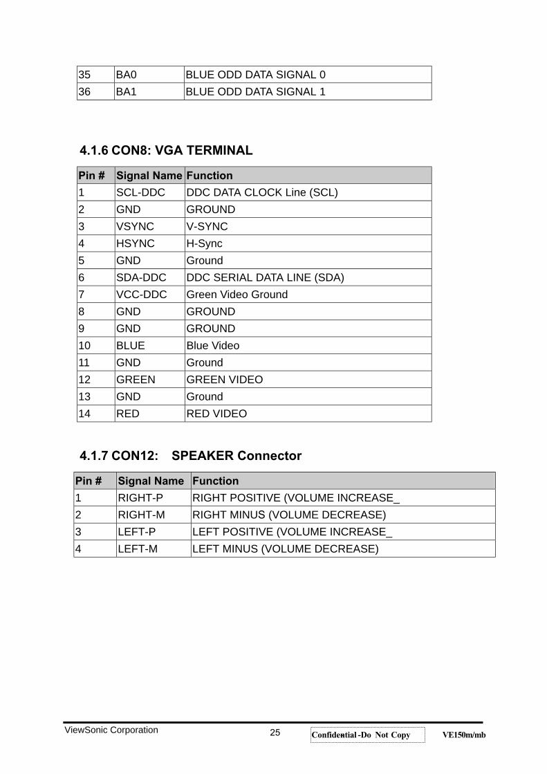
35 BA0 BLUE ODD DATA SIGNAL 0 36 BA1 BLUE ODD DATA SIGNAL 1
4.1.6 CON8: VGA TERMINAL
Pin # Signal Name Function
1 SCL-DDC DDC DATA CLOCK Line (SCL) 2 GND GROUND 3 VSYNC V-SYNC 4 HSYNC H-Sync 5 GND Ground 6 SDA-DDC DDC SERIAL DATA LINE (SDA) 7 VCC-DDC Green Video Ground 8 GND GROUND 9 GND GROUND 10 BLUE Blue Video 11 GND Ground 12 GREEN GREEN VIDEO 13 GND Ground 14 RED RED VIDEO
4.1.7 CON12: SPEAKER Connector
Pin # Signal Name Function
1 RIGHT-P RIGHT POSITIVE (VOLUME INCREASE_ 2 RIGHT-M RIGHT MINUS (VOLUME DECREASE) 3 LEFT-P LEFT POSITIVE (VOLUME INCREASE_ 4 LEFT-M LEFT MINUS (VOLUME DECREASE)
ViewSonic Corporation 25 Confidential -- Do Not Copy VE150m/mb
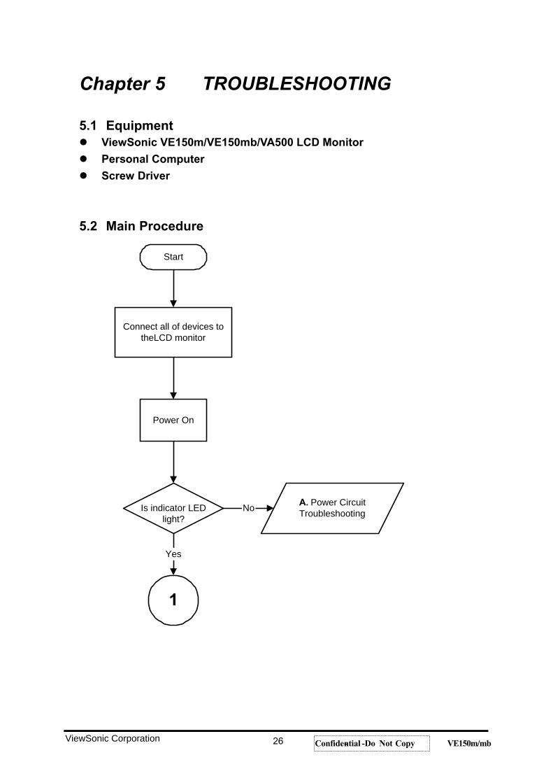
Chapter 5 TROUBLESHOOTING
5.1 Equipment ViewSonic VE150m/VE150mb/VA500 LCD Monitor
Personal Computer
Screw Driver
5.2 Main Procedure
Start
Connect all of devices totheLCD monitor
Power On
Is indicator LEDlight?
A. Power CircuitTroubleshooting
Yes
No
1
ViewSonic Corporation 26 Confidential -- Do Not Copy VE150m/mb
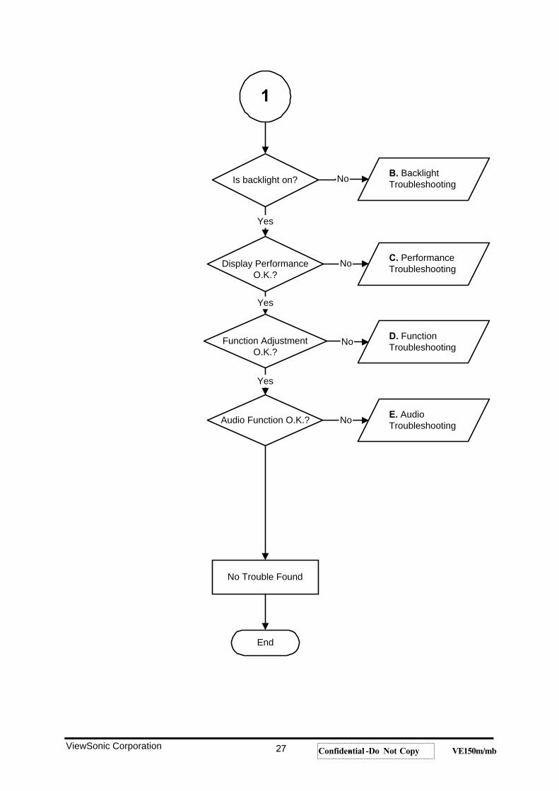
Is backlight on?
Display PerformanceO.K.?
Function AdjustmentO.K.?
Audio Function O.K.?
No Trouble Found
End
B. BacklightTroubleshooting
C. PerformanceTroubleshooting
D. FunctionTroubleshooting
E. AudioTroubleshooting
Yes
Yes
Yes
No
No
No
No
1
ViewSonic Corporation 27 Confidential -- Do Not Copy VE150m/mb
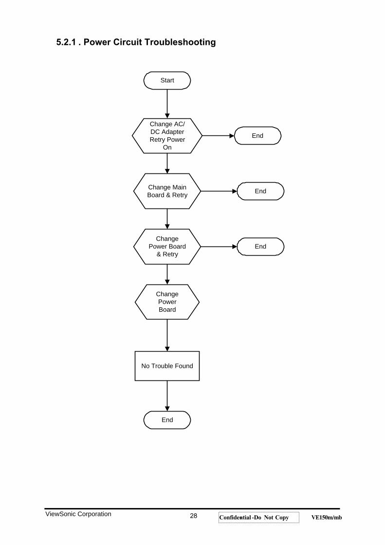
5.2.1 . Power Circuit Troubleshooting
Start
Change AC/DC AdapterRetry Power
On
Change MainBoard & Retry
ChangePower Board
& Retry
ChangePowerBoard
No Trouble Found
End
End
End
End
ViewSonic Corporation 28 Confidential -- Do Not Copy VE150m/mb
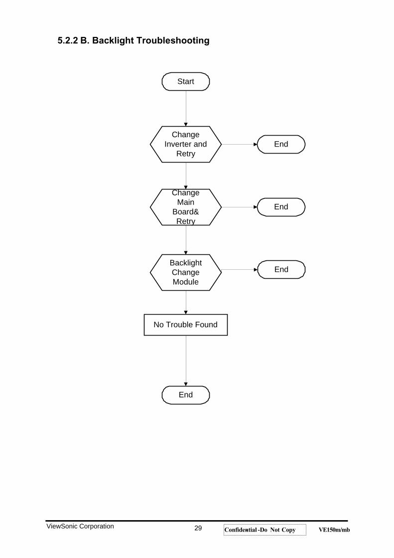
5.2.2 B. Backlight Troubleshooting
Start
ChangeInverter and
Retry
No Trouble Found
End
End
End
EndBacklightChangeModule
ChangeMain
Board&Retry
ViewSonic Corporation 29 Confidential -- Do Not Copy VE150m/mb
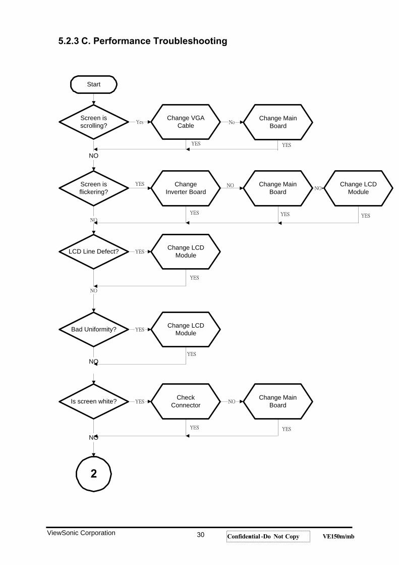
5.2.3 C. Performance Troubleshooting
Start
Screen isflickering?
Change VGACable
Change MainBoard
Bad Uniformity?
Is screen white?
NO
NO
Screen isscrolling?
LCD Line Defect?
ChangeInverter Board
Change LCDModule
Change LCDModule
CheckConnector
Change MainBoard
Change LCDModule
NO
Change MainBoard
2
ViewSonic Corporation 30 Confidential -- Do Not Copy VE150m/mb
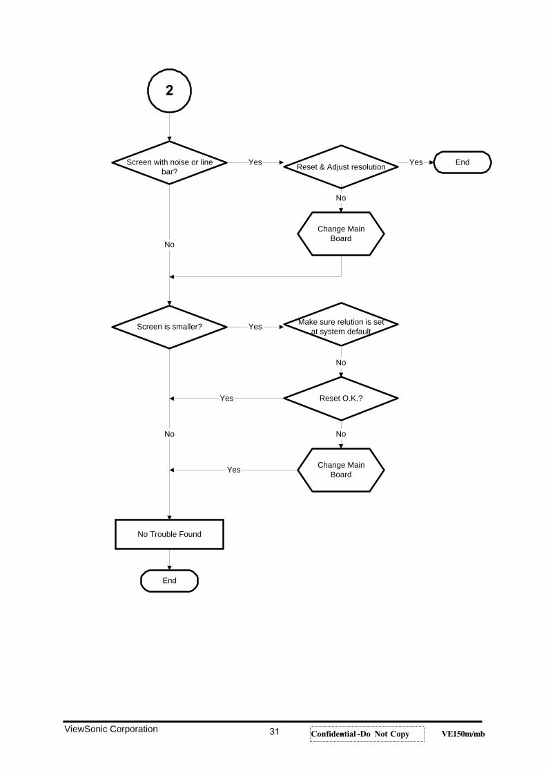
2
Screen with noise or linebar? Reset & Adjust resolution End
Change MainBoard
Screen is smaller? Make sure relution is setat system default
Reset O.K.?
Change MainBoard
No Trouble Found
End
No
No
Yes
No
Yes
No
Yes
No
YesYes
ViewSonic Corporation 31 Confidential -- Do Not Copy VE150m/mb
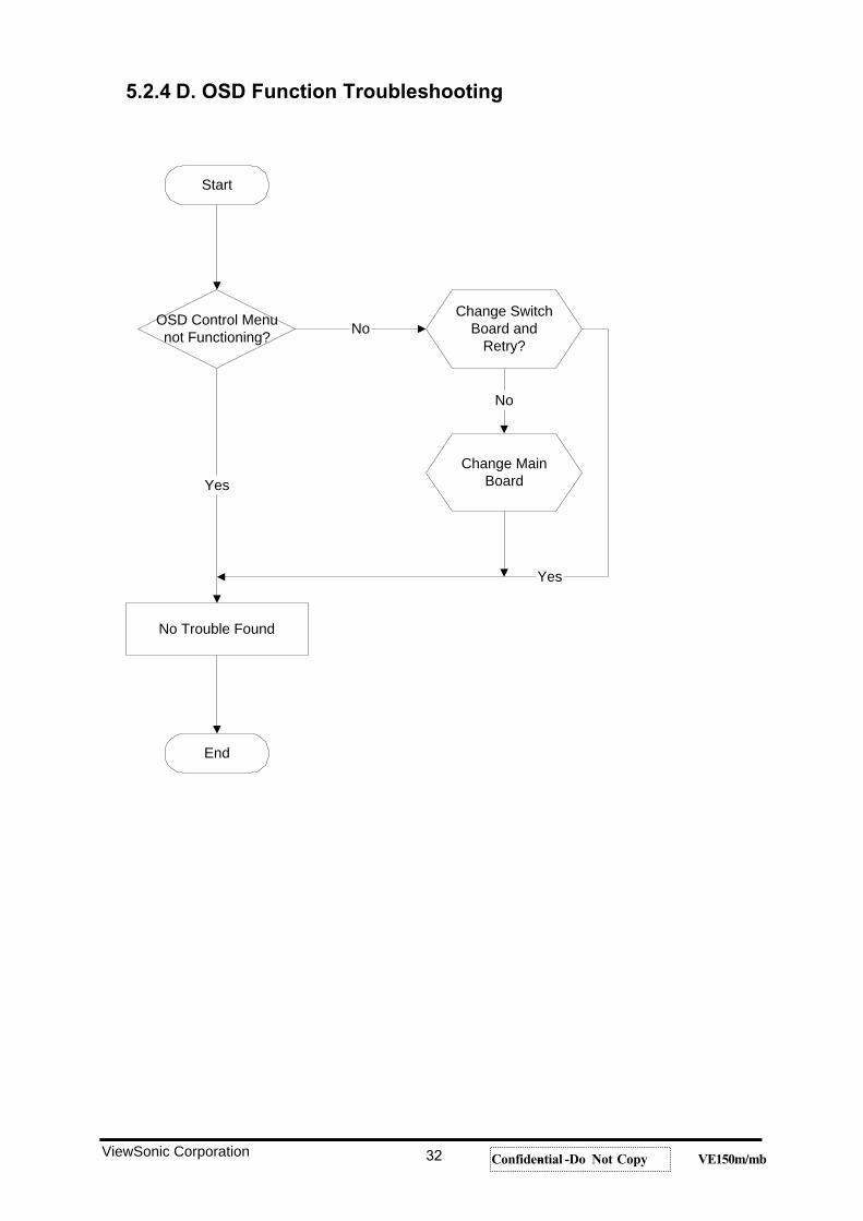
5.2.4 D. OSD Function Troubleshooting
Start
OSD Control Menunot Functioning?
Change SwitchBoard and
Retry?
Change MainBoard
No Trouble Found
End
No
No
Yes
Yes
ViewSonic Corporation 32 Confidential -- Do Not Copy VE150m/mb
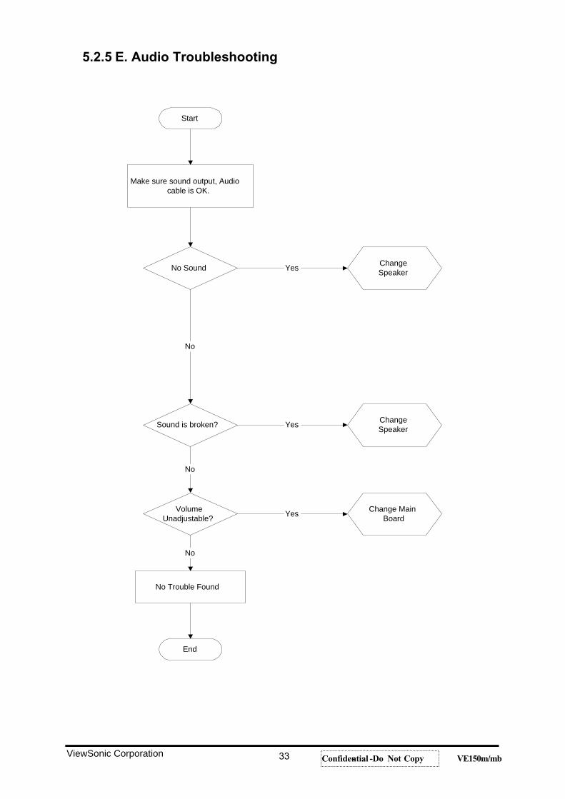
5.2.5 E. Audio Troubleshooting
Start
Make sure sound output, Audiocable is OK.
No Sound ChangeSpeaker
ChangeSpeaker
Change MainBoard
Sound is broken?
VolumeUnadjustable?
No Trouble Found
End
No
Yes
Yes
No
Yes
No
ViewSonic Corporation 33 Confidential -- Do Not Copy VE150m/mb
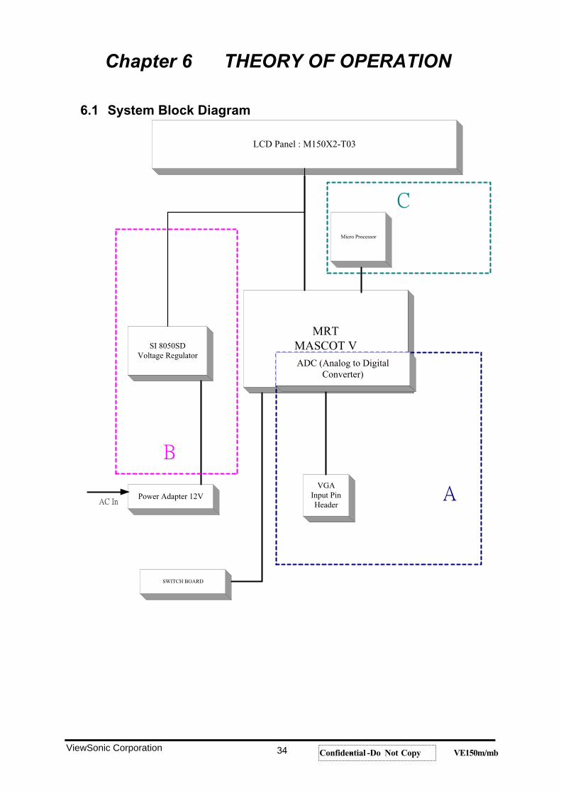
Chapter 6 THEORY OF OPERATION
6.1 System Block Diagram
LCD Panel : M150X2-T03
SI 8050SDVoltage Regulator
MRTMASCOT V
Power Adapter 12VVGA
Input PinHeader
SWITCH BOARD
Micro Processor
ADC (Analog to DigitalConverter)
ViewSonic Corporation 34 Confidential -- Do Not Copy VE150m/mb
6.2 System Circuitry Description
BLOCK A. In reference to the system block diagram of the monitor’scircuitry shown on the previous page, the analog RGB inputsare amplified and sent through an analog-to-digital converter (ADC)
to a digital signal processor (DSP) that generates digital RGB
signals for controlling LCA panel.
BLOCK B.A second power supply converts a single 12V supply to the various voltages needed to run the LCD panel and the inverter driving the display’s backlights.
BLOCK C.SYNC SIGNAL PROCESSOR. This processor determines the
polarity of the horizontal and vertical sync signals, generates a
fixed-polarity synchronized clock signal and provides data for use by the microprocessor in selecting circuit control parameters
from EEPROM tables.
ViewSonic Corporation 35 Confidential -- Do Not Copy VE150m/mb
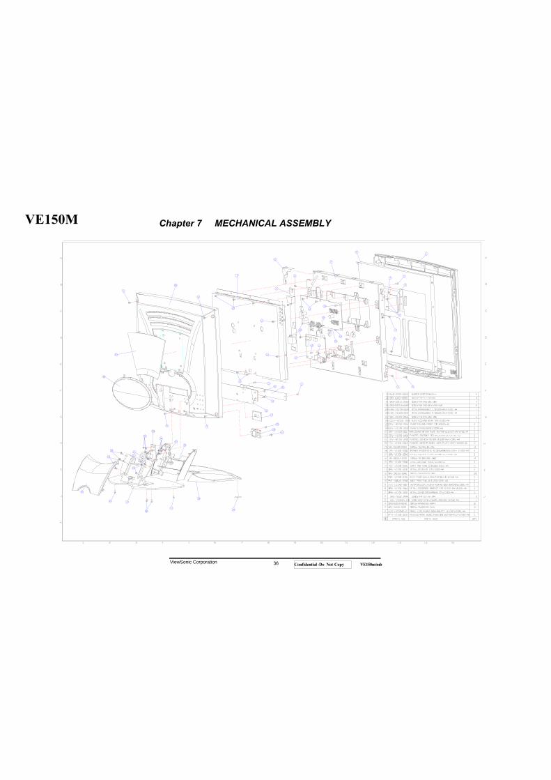
VE150M
ViewSonic Corporation 36 Confidential -- Do Not Copy VE150m/mb
Chapter 7 MECHANICAL ASSEMBLY
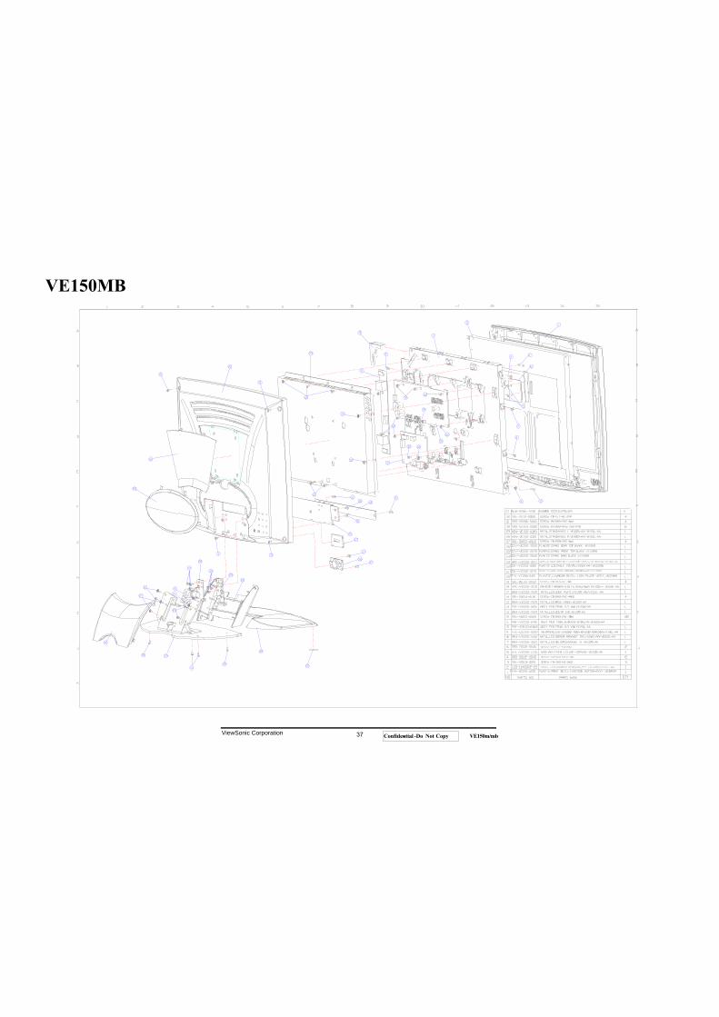
VE150MB
ViewSonic Corporation 37 Confidential -- Do Not Copy VE150m/mb
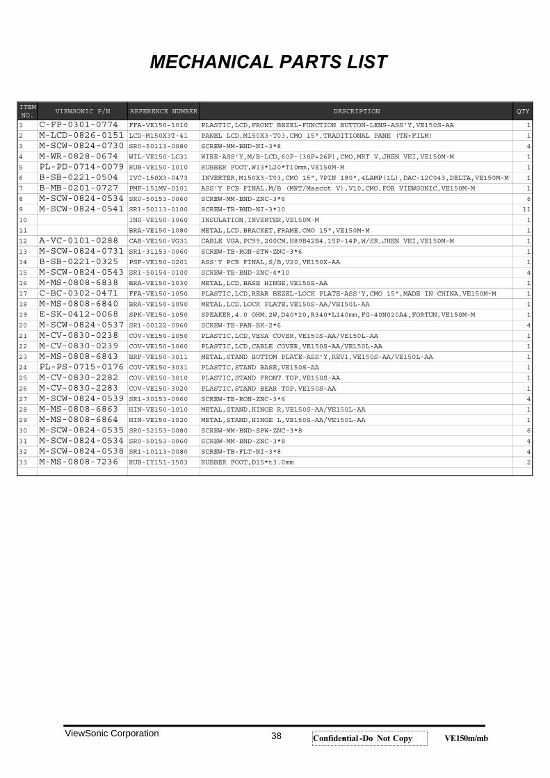
MECHANICAL PARTS LIST
ViewSonic Corporation 38 Confidential -- Do Not Copy VE150m/mb
ITEMNO.
VIEWSONIC P/N REFERENCE NUMBER DESCRIPTION QTY
1 C-FP-0301-0774 FFA-VE150-1010 PLASTIC,LCD,FRONT BEZEL-FUNCTION BUTTON-LENS-ASS'Y,VE150S-AA 1
2 M-LCD-0826-0151 LCD-M150X3T-41 PANEL LCD,M150X3-T03,CMO 15",TRADITIONAL PANE (TN+FILM) 1
3 M-SCW-0824-0730 SR0-50113-0080 SCREW-MM-BND-NI-3*8 4
4 M-WR-0828-0674 WIL-VE150-LC31 WIRE-ASS'Y,M/B-LCD,60P-(30P+26P),CMO,MRT V,JHEN VEI,VE150M-M 1
5 PL-PD-0714-0079 RUB-VE150-1010 RUBBER FOOT,W13*L20*T10mm,VE150M-M 1
6 B-SB-0221-0504 IVC-150X3-0473 INVERTER,M150X3-T03,CMO 15",7PIN 180°,4LAMP(1L),DAC-12C043,DELTA,VE150M-M 1
7 B-MB-0201-0727 PMF-151MV-0101 ASS'Y PCB FINAL,M/B (MRT/Mascot V),V10,CMO,FOR VIEWSONIC,VE150M-M 1
8 M-SCW-0824-0534 SR0-50153-0060 SCREW-MM-BND-ZNC-3*6 6
9 M-SCW-0824-0541 SR1-50113-0100 SCREW-TB-BND-NI-3*10 11
10 INS-VE150-1060 INSULATION,INVERTER,VE150M-M 1
11 BRA-VE150-1080 METAL,LCD,BRACKET,FRAME,CMO 15",VE150M-M 1
12 A-VC-0101-0288 CAB-VE150-VG31 CABLE VGA,PC99,200CM,H89B42B4,15P-14P,W/SR,JHEN VEI,VE150M-M 1
13 M-SCW-0824-0731 SR1-31153-0060 SCREW-TB-RON-STW-ZNC-3*6 1
14 B-SB-0221-0325 PSF-VE150-0201 ASS'Y PCB FINAL,S/B,V20,VE150X-AA 1
15 M-SCW-0824-0543 SR1-50154-0100 SCREW-TB-BND-ZNC-4*10 4
16 M-MS-0808-6838 BRA-VE150-1030 METAL,LCD,BASE HINGE,VE150S-AA 1
17 C-BC-0302-0471 FFA-VE150-1050 PLASTIC,LCD,REAR BEZEL-LOCK PLATE-ASS'Y,CMO 15",MADE IN CHINA,VE150M-M 1
18 M-MS-0808-6840 BRA-VE150-1050 METAL,LCD,LOCK PLATE,VE150S-AA/VE150L-AA 1
19 E-SK-0412-0068 SPK-VE150-1050 SPEAKER,4.0 OHM,2W,D40*20,R340*L140mm,FG-40N020A4,FORTUN,VE150M-M 1
20 M-SCW-0824-0537 SR1-00122-0060 SCREW-TB-PAN-BK-2*6 4
21 M-CV-0830-0238 COV-VE150-1050 PLASTIC,LCD,VESA COVER,VE150S-AA/VE150L-AA 1
22 M-CV-0830-0239 COV-VE150-1060 PLASTIC,LCD,CABLE COVER,VE150S-AA/VE150L-AA 1
23 M-MS-0808-6843 BRF-VE150-3011 METAL,STAND BOTTOM PLATE-ASS'Y,REV1,VE150S-AA/VE150L-AA 1
24 PL-PS-0715-0176 COV-VE150-3031 PLASTIC,STAND BASE,VE150S-AA 1
25 M-CV-0830-2282 COV-VE150-3010 PLASTIC,STAND FRONT TOP,VE150S-AA 1
26 M-CV-0830-2283 COV-VE150-3020 PLASTIC,STAND BEAR TOP,VE150S-AA 1
27 M-SCW-0824-0539 SR1-30153-0060 SCREW-TB-RON-ZNC-3*6 4
28 M-MS-0808-6863 HIN-VE150-1010 METAL,STAND,HINGE R,VE150S-AA/VE150L-AA 1
29 M-MS-0808-6864 HIN-VE150-1020 METAL,STAND,HINGE L,VE150S-AA/VE150L-AA 1
30 M-SCW-0824-0535 SR0-52153-0080 SCREW-MM-BND-SPW-ZNC-3*8 6
31 M-SCW-0824-0534 SR0-50153-0060 SCREW-MM-BND-ZNC-3*8 4
32 M-SCW-0824-0538 SR1-10113-0080 SCREW-TB-FLT-NI-3*8 4
33 M-MS-0808-7236 RUB-IY151-1503 RUBBER FOOT,D15*t3.0mm 2
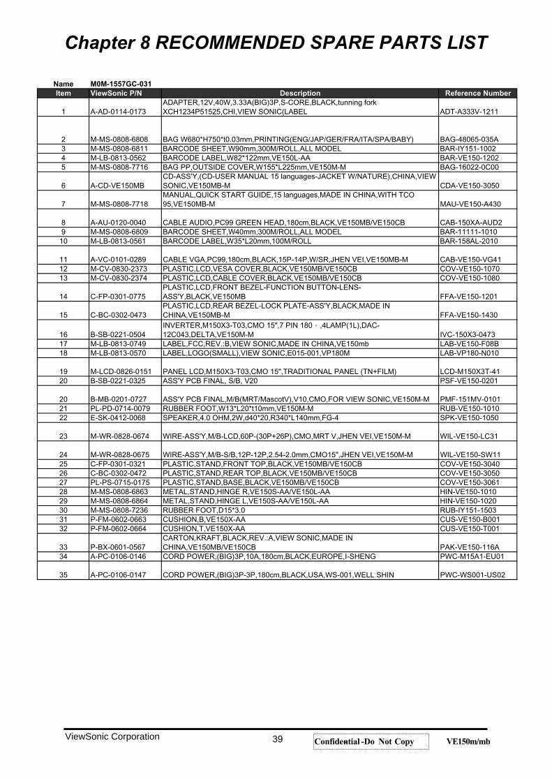
Chapter 8 RECOMMENDED SPARE PARTS LIST
ViewSonic Corporation 39 Confidential -- Do Not Copy VE150m/mb
Name M0M-1557GC-031Item ViewSonic P/N Description Reference Number
1 A-AD-0114-0173ADAPTER,12V,40W,3.33A(BIG)3P,S-CORE,BLACK,tunning forkXCH1234P51525,CHI,VIEW SONIC(LABEL ADT-A333V-1211
2 M-MS-0808-6808 BAG W680*H750*t0.03mm,PRINTING(ENG/JAP/GER/FRA/ITA/SPA/BABY) BAG-48065-035A3 M-MS-0808-6811 BARCODE SHEET,W90mm,300M/ROLL,ALL MODEL BAR-IY151-10024 M-LB-0813-0562 BARCODE LABEL,W82*122mm,VE150L-AA BAR-VE150-12025 M-MS-0808-7716 BAG PP,OUTSIDE COVER,W155*L225mm,VE150M-M BAG-16022-0C00
6 A-CD-VE150MBCD-ASS'Y,(CD-USER MANUAL 15 languages-JACKET W/NATURE),CHINA,VIEWSONIC,VE150MB-M CDA-VE150-3050
7 M-MS-0808-7718MANUAL,QUICK START GUIDE,15 languages,MADE IN CHINA,WITH TCO95,VE150MB-M MAU-VE150-A430
8 A-AU-0120-0040 CABLE AUDIO,PC99 GREEN HEAD,180cm,BLACK,VE150MB/VE150CB CAB-150XA-AUD29 M-MS-0808-6809 BARCODE SHEET,W40mm,300M/ROLL,ALL MODEL BAR-11111-1010
10 M-LB-0813-0561 BARCODE LABEL,W35*L20mm,100M/ROLL BAR-158AL-2010
11 A-VC-0101-0289 CABLE VGA,PC99,180cm,BLACK,15P-14P,W/SR,JHEN VEI,VE150MB-M CAB-VE150-VG4112 M-CV-0830-2373 PLASTIC,LCD,VESA COVER,BLACK,VE150MB/VE150CB COV-VE150-107013 M-CV-0830-2374 PLASTIC,LCD,CABLE COVER,BLACK,VE150MB/VE150CB COV-VE150-1080
14 C-FP-0301-0775PLASTIC,LCD,FRONT BEZEL-FUNCTION BUTTON-LENS-ASS'Y,BLACK,VE150MB FFA-VE150-1201
15 C-BC-0302-0473PLASTIC,LCD,REAR BEZEL-LOCK PLATE-ASS'Y,BLACK,MADE INCHINA,VE150MB-M FFA-VE150-1430
16 B-SB-0221-0504INVERTER,M150X3-T03,CMO 15",7 PIN 180 ,4LAMP(1L),DAC-12C043,DELTA,VE150M-M IVC-150X3-0473
17 M-LB-0813-0749 LABEL,FCC,REV.:B,VIEW SONIC,MADE IN CHINA,VE150mb LAB-VE150-F08B18 M-LB-0813-0570 LABEL,LOGO(SMALL),VIEW SONIC,E015-001,VP180M LAB-VP180-N010
19 M-LCD-0826-0151 PANEL LCD,M150X3-T03,CMO 15",TRADITIONAL PANEL (TN+FILM) LCD-M150X3T-4120 B-SB-0221-0325 ASS'Y PCB FINAL, S/B, V20 PSF-VE150-0201
20 B-MB-0201-0727 ASS'Y PCB FINAL,M/B(MRT/MascotV),V10,CMO,FOR VIEW SONIC,VE150M-M PMF-151MV-010121 PL-PD-0714-0079 RUBBER FOOT,W13*L20*t10mm,VE150M-M RUB-VE150-101022 E-SK-0412-0068 SPEAKER,4.0 OHM,2W,d40*20,R340*L140mm,FG-4 SPK-VE150-1050
23 M-WR-0828-0674 WIRE-ASS'Y,M/B-LCD,60P-(30P+26P),CMO,MRT V,JHEN VEI,VE150M-M WIL-VE150-LC31
24 M-WR-0828-0675 WIRE-ASS'Y,M/B-S/B,12P-12P,2.54-2.0mm,CMO15",JHEN VEI,VE150M-M WIL-VE150-SW1125 C-FP-0301-0321 PLASTIC,STAND,FRONT TOP,BLACK,VE150MB/VE150CB COV-VE150-304026 C-BC-0302-0472 PLASTIC,STAND,REAR TOP,BLACK,VE150MB/VE150CB COV-VE150-305027 PL-PS-0715-0175 PLASTIC,STAND,BASE,BLACK,VE150MB/VE150CB COV-VE150-306128 M-MS-0808-6863 METAL,STAND,HINGE R,VE150S-AA/VE150L-AA HIN-VE150-101029 M-MS-0808-6864 METAL,STAND,HINGE L,VE150S-AA/VE150L-AA HIN-VE150-102030 M-MS-0808-7236 RUBBER FOOT,D15*3.0 RUB-IY151-150331 P-FM-0602-0663 CUSHION,B,VE150X-AA CUS-VE150-B00132 P-FM-0602-0664 CUSHION,T,VE150X-AA CUS-VE150-T001
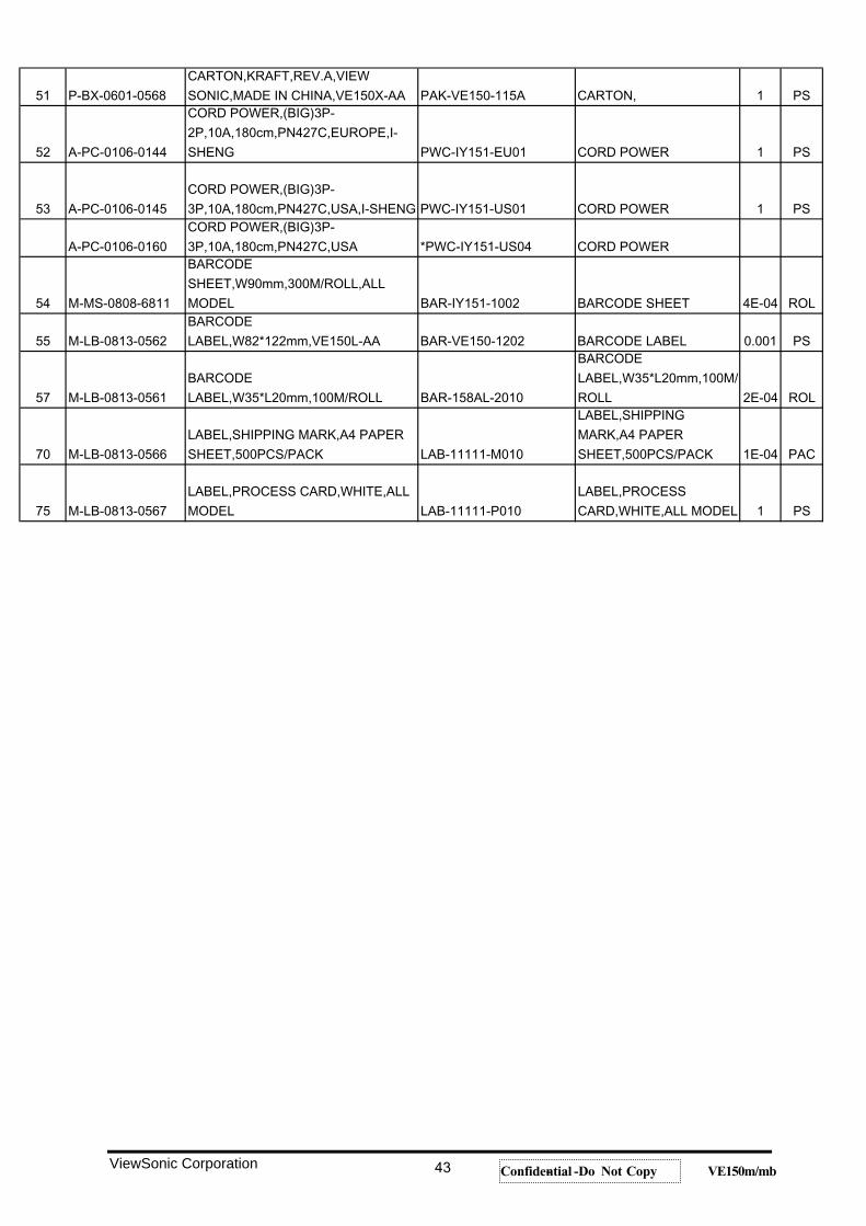
33 P-BX-0601-0567CARTON,KRAFT,BLACK,REV.:A,VIEW SONIC,MADE INCHINA,VE150MB/VE150CB PAK-VE150-116A
34 A-PC-0106-0146 CORD POWER,(BIG)3P,10A,180cm,BLACK,EUROPE,I-SHENG PWC-M15A1-EU01
35 A-PC-0106-0147 CORD POWER,(BIG)3P-3P,180cm,BLACK,USA,WS-001,WELL SHIN PWC-WS001-US02
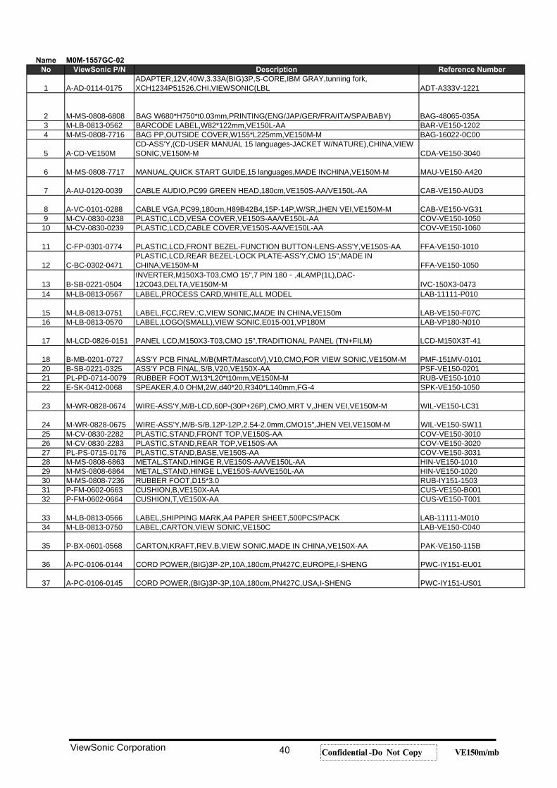
Name M0M-1557GC-02No ViewSonic P/N Description Reference Number
1 A-AD-0114-0175ADAPTER,12V,40W,3.33A(BIG)3P,S-CORE,IBM GRAY,tunning fork,XCH1234P51526,CHI,VIEWSONIC(LBL ADT-A333V-1221
2 M-MS-0808-6808 BAG W680*H750*t0.03mm,PRINTING(ENG/JAP/GER/FRA/ITA/SPA/BABY) BAG-48065-035A3 M-LB-0813-0562 BARCODE LABEL,W82*122mm,VE150L-AA BAR-VE150-12024 M-MS-0808-7716 BAG PP,OUTSIDE COVER,W155*L225mm,VE150M-M BAG-16022-0C00
5 A-CD-VE150MCD-ASS'Y,(CD-USER MANUAL 15 languages-JACKET W/NATURE),CHINA,VIEWSONIC,VE150M-M CDA-VE150-3040
6 M-MS-0808-7717 MANUAL,QUICK START GUIDE,15 languages,MADE INCHINA,VE150M-M MAU-VE150-A420
7 A-AU-0120-0039 CABLE AUDIO,PC99 GREEN HEAD,180cm,VE150S-AA/VE150L-AA CAB-VE150-AUD3
8 A-VC-0101-0288 CABLE VGA,PC99,180cm,H89B42B4,15P-14P,W/SR,JHEN VEI,VE150M-M CAB-VE150-VG319 M-CV-0830-0238 PLASTIC,LCD,VESA COVER,VE150S-AA/VE150L-AA COV-VE150-105010 M-CV-0830-0239 PLASTIC,LCD,CABLE COVER,VE150S-AA/VE150L-AA COV-VE150-1060
11 C-FP-0301-0774 PLASTIC,LCD,FRONT BEZEL-FUNCTION BUTTON-LENS-ASS'Y,VE150S-AA FFA-VE150-1010
12 C-BC-0302-0471PLASTIC,LCD,REAR BEZEL-LOCK PLATE-ASS'Y,CMO 15",MADE INCHINA,VE150M-M FFA-VE150-1050
13 B-SB-0221-0504INVERTER,M150X3-T03,CMO 15",7 PIN 180 ,4LAMP(1L),DAC-12C043,DELTA,VE150M-M IVC-150X3-0473
14 M-LB-0813-0567 LABEL,PROCESS CARD,WHITE,ALL MODEL LAB-11111-P010
15 M-LB-0813-0751 LABEL,FCC,REV.:C,VIEW SONIC,MADE IN CHINA,VE150m LAB-VE150-F07C16 M-LB-0813-0570 LABEL,LOGO(SMALL),VIEW SONIC,E015-001,VP180M LAB-VP180-N010
17 M-LCD-0826-0151 PANEL LCD,M150X3-T03,CMO 15",TRADITIONAL PANEL (TN+FILM) LCD-M150X3T-41
18 B-MB-0201-0727 ASS'Y PCB FINAL,M/B(MRT/MascotV),V10,CMO,FOR VIEW SONIC,VE150M-M PMF-151MV-010120 B-SB-0221-0325 ASS'Y PCB FINAL,S/B,V20,VE150X-AA PSF-VE150-020121 PL-PD-0714-0079 RUBBER FOOT,W13*L20*t10mm,VE150M-M RUB-VE150-101022 E-SK-0412-0068 SPEAKER,4.0 OHM,2W,d40*20,R340*L140mm,FG-4 SPK-VE150-1050
23 M-WR-0828-0674 WIRE-ASS'Y,M/B-LCD,60P-(30P+26P),CMO,MRT V,JHEN VEI,VE150M-M WIL-VE150-LC31
24 M-WR-0828-0675 WIRE-ASS'Y,M/B-S/B,12P-12P,2.54-2.0mm,CMO15",JHEN VEI,VE150M-M WIL-VE150-SW1125 M-CV-0830-2282 PLASTIC,STAND,FRONT TOP,VE150S-AA COV-VE150-301026 M-CV-0830-2283 PLASTIC,STAND,REAR TOP,VE150S-AA COV-VE150-302027 PL-PS-0715-0176 PLASTIC,STAND,BASE,VE150S-AA COV-VE150-303128 M-MS-0808-6863 METAL,STAND,HINGE R,VE150S-AA/VE150L-AA HIN-VE150-101029 M-MS-0808-6864 METAL,STAND,HINGE L,VE150S-AA/VE150L-AA HIN-VE150-102030 M-MS-0808-7236 RUBBER FOOT,D15*3.0 RUB-IY151-150331 P-FM-0602-0663 CUSHION,B,VE150X-AA CUS-VE150-B00132 P-FM-0602-0664 CUSHION,T,VE150X-AA CUS-VE150-T001
33 M-LB-0813-0566 LABEL,SHIPPING MARK,A4 PAPER SHEET,500PCS/PACK LAB-11111-M01034 M-LB-0813-0750 LABEL,CARTON,VIEW SONIC,VE150C LAB-VE150-C040
35 P-BX-0601-0568 CARTON,KRAFT,REV.B,VIEW SONIC,MADE IN CHINA,VE150X-AA PAK-VE150-115B
36 A-PC-0106-0144 CORD POWER,(BIG)3P-2P,10A,180cm,PN427C,EUROPE,I-SHENG PWC-IY151-EU01
37 A-PC-0106-0145 CORD POWER,(BIG)3P-3P,10A,180cm,PN427C,USA,I-SHENG PWC-IY151-US01
ViewSonic Corporation 40 Confidential -- Do Not Copy VE150m/mb
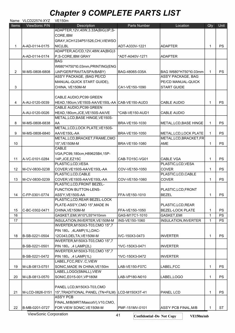
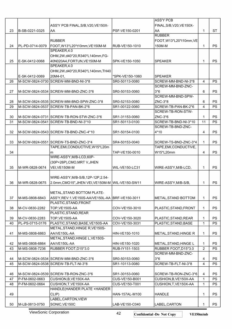
Chapter 9 COMPLETE PARTS LIST
ViewSonic Corporation 41 Confidential -- Do Not Copy VE150m/mb
ViewSonic Corporation 42 Confidential -- Do Not Copy VE150m/mb
ViewSonic Corporation 43 Confidential -- Do Not Copy VE150m/mb
ViewSonic Corporation 44 Confidential -- Do Not Copy VE150m/mb
ViewSonic Corporation 45 Confidential -- Do Not Copy VE150m/mb
ViewSonic Corporation 46 Confidential -- Do Not Copy VE150m/mb
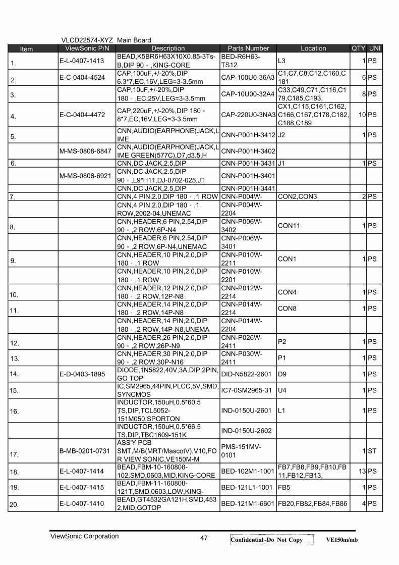
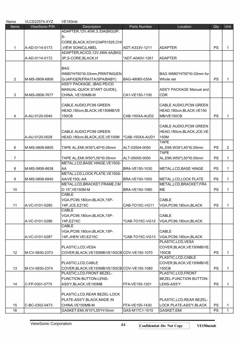
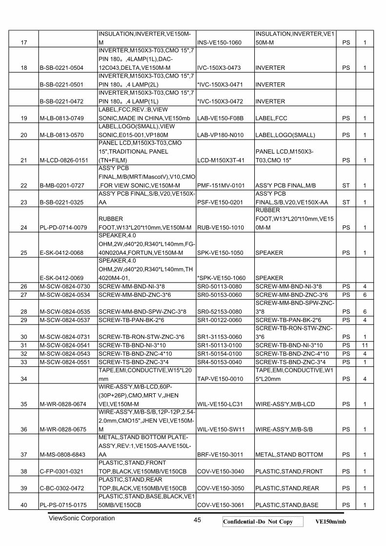
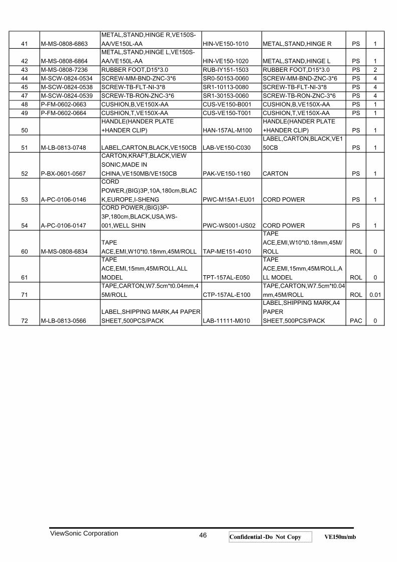
VLCD22574-XYZ Main BoardViewSonic P/N Description Parts Number Location QTY UNI
E-L-0407-1413BEAD,K5BR6H63X10X0.85-3Ts-B,DIP 90 ,KING-CORE
BED-R6H63-TS12
L3 1 PS
E-C-0404-4524CAP,100uF,+/-20%,DIP6.3*7,EC,16V,LEG=3-3.5mm
CAP-100U0-36A3C1,C7,C8,C12,C160,C181
6 PS
CAP,10uF,+/-20%,DIP180 ,EC,25V,LEG=3-3.5mm
CAP-10U00-32A4C33,C49,C71,C116,C179,C185,C193,
8 PS
E-C-0404-4472CAP,220uF,+/-20%,DIP 1808*7,EC,16V,LEG=3-3.5mm
CAP-220U0-3NA3CX1,C115,C161,C162,C166,C167,C178,C182,C188,C189
10 PS
CNN,AUDIO(EARPHONE)JACK,LIME
CNN-P001H-3412 J2 1 PS
M-MS-0808-6847CNN,AUDIO(EARPHONE)JACK,LIME GREEN(577C),D7,d3.5,H
CNN-P001H-3402
CNN,DC JACK,2.5,DIP CNN-P001H-3431 J1 1 PS
M-MS-0808-6921CNN,DC JACK,2.5,DIP90 ,L9*H11,DJ-0702-025,JT
CNN-P001H-3401
CNN,DC JACK,2.5,DIP CNN-P001H-3441CNN,4 PIN,2.0,DIP 180 ,1 ROW CNN-P004W- CON2,CON3 2 PSCNN,4 PIN,2.0,DIP 180 ,1ROW,2002-04,UNEMAC
CNN-P004W-2204
CNN,HEADER,6 PIN,2.54,DIP90 ,2 ROW,6P-N4
CNN-P006W-3402
CON11 1 PS
CNN,HEADER,6 PIN,2.54,DIP90 ,2 ROW,6P-N4,UNEMAC
CNN-P006W-3401
CNN,HEADER,10 PIN,2.0,DIP180 ,1 ROW
CNN-P010W-2211
CON1 1 PS
CNN,HEADER,10 PIN,2.0,DIP180 ,1 ROW
CNN-P010W-2201
CNN,HEADER,12 PIN,2.0,DIP180 ,2 ROW,12P-N8
CNN-P012W-2214
CON4 1 PS
CNN,HEADER,14 PIN,2.0,DIP180 ,2 ROW,14P-N8
CNN-P014W-2214
CON8 1 PS
CNN,HEADER,14 PIN,2.0,DIP180 ,2 ROW,14P-N8,UNEMA
CNN-P014W-2204
CNN,HEADER,26 PIN,2.0,DIP90 ,2 ROW,26P-N9
CNN-P026W-2411
P2 1 PS
CNN,HEADER,30 PIN,2.0,DIP90 ,2 ROW,30P-N16
CNN-P030W-2411
P1 1 PS
E-D-0403-1895DIODE,1N5822,40V,3A,DIP,2PIN,GO TOP
DID-N5822-2601 D9 1 PS
IC,SM2965,44PIN,PLCC,5V,SMD,SYNCMOS
IC7-0SM2965-31 U4 1 PS
INDUCTOR,150uH,0.5*60.5TS,DIP,TCL5052-151M050,SPORTON
IND-0150U-2601 L1 1 PS
INDUCTOR,150uH,0.5*66.5TS,DIP,TBC1609-151K
IND-0150U-2602
B-MB-0201-0731ASS'Y PCBSMT,M/B(MRT/MascotV),V10,FOR VIEW SONIC,VE150M-M
PMS-151MV-0101
1 ST
E-L-0407-1414BEAD,FBM-10-160808-102,SMD,0603,MID,KING-CORE
BED-102M1-1001FB7,FB8,FB9,FB10,FB11,FB12,FB13,
13 PS
E-L-0407-1415BEAD,FBM-11-160808-121T,SMD,0603,LOW,KING-
BED-121L1-1001 FB5 1 PS
E-L-0407-1410BEAD,GT4532GA121H,SMD,4532,MID,GOTOP
BED-121M1-6601 FB20,FB82,FB84,FB86 4 PS
ViewSonic Corporation 47 Confidential -- Do Not Copy VE150m/mb
1.
3.
2.
Item
6.
5.
4.
7.
10.
9.
8.
19.
20.
17.
16.
15.
14.
11.
13.
.
12.
.
18.
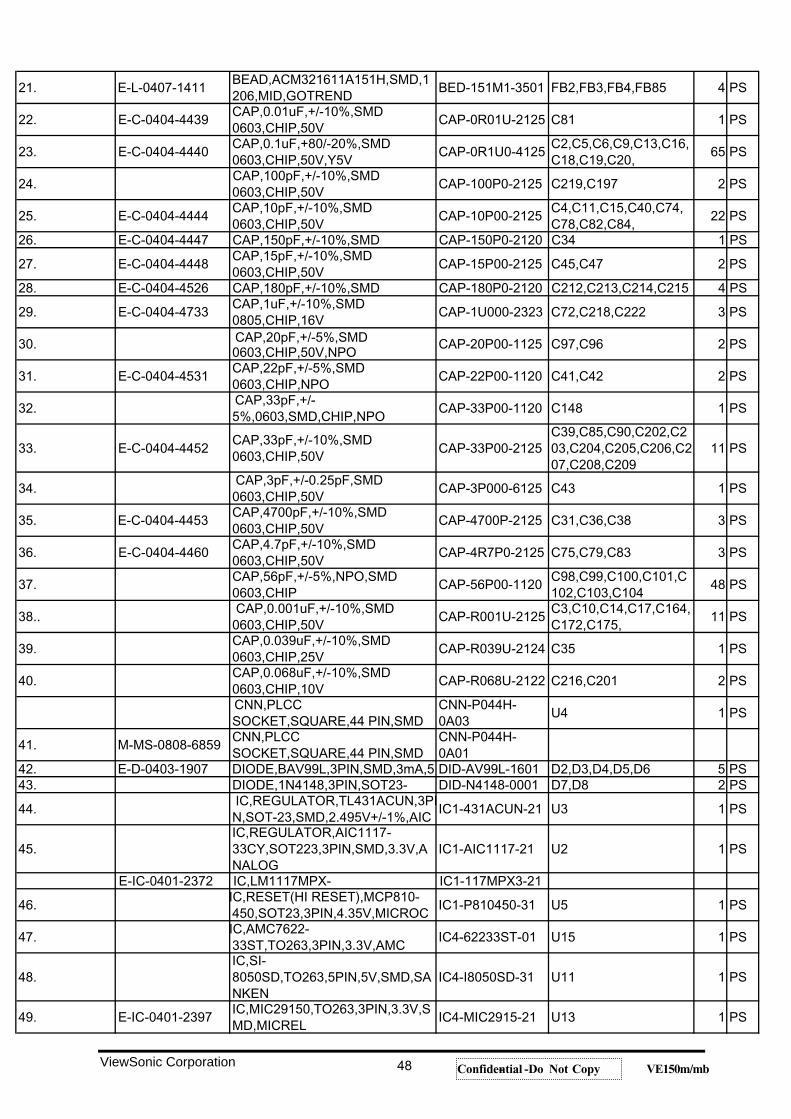
21. E-L-0407-1411BEAD,ACM321611A151H,SMD,1206,MID,GOTREND
BED-151M1-3501 FB2,FB3,FB4,FB85 4 PS
22. E-C-0404-4439CAP,0.01uF,+/-10%,SMD0603,CHIP,50V
CAP-0R01U-2125 C81 1 PS
23. E-C-0404-4440CAP,0.1uF,+80/-20%,SMD0603,CHIP,50V,Y5V
CAP-0R1U0-4125C2,C5,C6,C9,C13,C16,C18,C19,C20,
65 PS
24.CAP,100pF,+/-10%,SMD0603,CHIP,50V
CAP-100P0-2125 C219,C197 2 PS
25. E-C-0404-4444CAP,10pF,+/-10%,SMD0603,CHIP,50V
CAP-10P00-2125C4,C11,C15,C40,C74,C78,C82,C84,
22 PS
26. E-C-0404-4447 CAP,150pF,+/-10%,SMD CAP-150P0-2120 C34 1 PS
27. E-C-0404-4448CAP,15pF,+/-10%,SMD0603,CHIP,50V
CAP-15P00-2125 C45,C47 2 PS
28. E-C-0404-4526 CAP,180pF,+/-10%,SMD CAP-180P0-2120 C212,C213,C214,C215 4 PS
29. E-C-0404-4733CAP,1uF,+/-10%,SMD0805,CHIP,16V
CAP-1U000-2323 C72,C218,C222 3 PS
30. CAP,20pF,+/-5%,SMD0603,CHIP,50V,NPO
CAP-20P00-1125 C97,C96 2 PS
31. E-C-0404-4531CAP,22pF,+/-5%,SMD0603,CHIP,NPO
CAP-22P00-1120 C41,C42 2 PS
32.CAP,33pF,+/-5%,0603,SMD,CHIP,NPO
CAP-33P00-1120 C148 1 PS
33. E-C-0404-4452CAP,33pF,+/-10%,SMD0603,CHIP,50V
CAP-33P00-2125C39,C85,C90,C202,C203,C204,C205,C206,C207,C208,C209
11 PS
34.CAP,3pF,+/-0.25pF,SMD0603,CHIP,50V
CAP-3P000-6125 C43 1 PS
35. E-C-0404-4453CAP,4700pF,+/-10%,SMD0603,CHIP,50V
CAP-4700P-2125 C31,C36,C38 3 PS
36. E-C-0404-4460CAP,4.7pF,+/-10%,SMD0603,CHIP,50V
CAP-4R7P0-2125 C75,C79,C83 3 PS
37.CAP,56pF,+/-5%,NPO,SMD0603,CHIP
CAP-56P00-1120C98,C99,C100,C101,C102,C103,C104
48 PS
38..CAP,0.001uF,+/-10%,SMD
0603,CHIP,50VCAP-R001U-2125
C3,C10,C14,C17,C164,C172,C175,
11 PS
39.CAP,0.039uF,+/-10%,SMD0603,CHIP,25V
CAP-R039U-2124 C35 1 PS
40.CAP,0.068uF,+/-10%,SMD0603,CHIP,10V
CAP-R068U-2122 C216,C201 2 PS
CNN,PLCCSOCKET,SQUARE,44 PIN,SMD
CNN-P044H-0A03
U4 1 PS
41. M-MS-0808-6859CNN,PLCCSOCKET,SQUARE,44 PIN,SMD
CNN-P044H-0A01
42. E-D-0403-1907 DIODE,BAV99L,3PIN,SMD,3mA,5 DID-AV99L-1601 D2,D3,D4,D5,D6 5 PS43. DIODE,1N4148,3PIN,SOT23- DID-N4148-0001 D7,D8 2 PS
44.IC,REGULATOR,TL431ACUN,3PIN,SOT-23,SMD,2.495V+/-1%,AIC
IC1-431ACUN-21 U3 1 PS
45.IC,REGULATOR,AIC1117-33CY,SOT223,3PIN,SMD,3.3V,ANALOG
IC1-AIC1117-21 U2 1 PS
E-IC-0401-2372 IC,LM1117MPX- IC1-117MPX3-21
46.IC,RESET(HI RESET),MCP810-450,SOT23,3PIN,4.35V,MICROC
IC1-P810450-31 U5 1 PS
47.IC,AMC7622-33ST,TO263,3PIN,3.3V,AMC
IC4-62233ST-01 U15 1 PS
48.IC,SI-8050SD,TO263,5PIN,5V,SMD,SANKEN
IC4-I8050SD-31 U11 1 PS
49. E-IC-0401-2397IC,MIC29150,TO263,3PIN,3.3V,SMD,MICREL
IC4-MIC2915-21 U13 1 PS
ViewSonic Corporation 48 Confidential -- Do Not Copy VE150m/mb
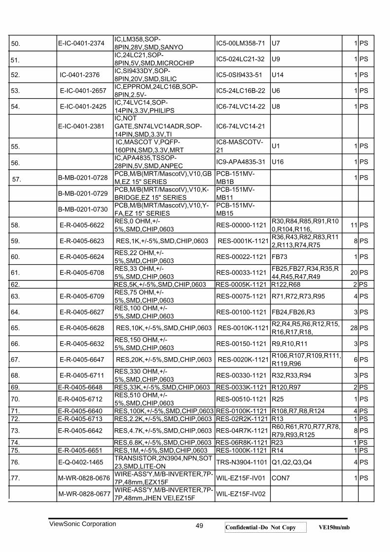
E-IC-0401-2374IC,LM358,SOP-8PIN,28V,SMD,SANYO
IC5-00LM358-71 U7 1 PS
IC,24LC21,SOP-8PIN,5V,SMD,MICROCHIP
IC5-024LC21-32 U9 1 PS
52. IC-0401-2376IC,SI9433DY,SOP-8PIN,20V,SMD,SILIC
IC5-0SI9433-51 U14 1 PS
53. E-IC-0401-2657IC,EPPROM,24LC16B,SOP-8PIN,2.5V-
IC5-24LC16B-22 U6 1 PS
54. E-IC-0401-2425IC,74LVC14,SOP-14PIN,3.3V,PHILIPS
IC6-74LVC14-22 U8 1 PS
E-IC-0401-2381IC,NOTGATE,SN74LVC14ADR,SOP-14PIN,SMD,3.3V,TI
IC6-74LVC14-21
IC,MASCOT V,PQFP-160PIN,SMD,3.3V,MRT
IC8-MASCOTV-21
U1 1 PS
IC,APA4835,TSSOP-28PIN,5V,SMD,ANPEC
IC9-APA4835-31 U16 1 PS
B-MB-0201-0728PCB,M/B(MRT/MascotV),V10,GBM,EZ 15" SERIES
PCB-151MV-MB1B
1 PS
B-MB-0201-0729PCB,M/B(MRT/MascotV),V10,K-BRIDGE,EZ 15" SERIES
PCB-151MV-MB11
B-MB-0201-0730PCB,M/B(MRT/MascotV),V10,Y-FA,EZ 15" SERIES
PCB-151MV-MB15
58. E-R-0405-6622RES,0 OHM,+/-5%,SMD,CHIP,0603
RES-00000-1121R30,R84,R85,R91,R100,R104,R116,
11 PS
59. E-R-0405-6623 RES,1K,+/-5%,SMD,CHIP,0603 RES-0001K-1121R36,R43,R82,R83,R112,R113,R74,R75
8 PS
60. E-R-0405-6624RES,22 OHM,+/-5%,SMD,CHIP,0603
RES-00022-1121 FB73 1 PS
61. E-R-0405-6708RES,33 OHM,+/-5%,SMD,CHIP,0603
RES-00033-1121FB25,FB27,R34,R35,R44,R45,R47,R49
20 PS
62. RES,5K,+/-5%,SMD,CHIP,0603 RES-0005K-1121 R122,R68 2 PS
63. E-R-0405-6709RES,75 OHM,+/-5%,SMD,CHIP,0603
RES-00075-1121 R71,R72,R73,R95 4 PS
64. E-R-0405-6627RES,100 OHM,+/-5%,SMD,CHIP,0603
RES-00100-1121 FB24,FB26,R3 3 PS
65. E-R-0405-6628 RES,10K,+/-5%,SMD,CHIP,0603 RES-0010K-1121R2,R4,R5,R6,R12,R15,R16,R17,R18,
28 PS
66. E-R-0405-6632RES,150 OHM,+/-5%,SMD,CHIP,0603
RES-00150-1121 R9,R10,R11 3 PS
.67. E-R-0405-6647 RES,20K,+/-5%,SMD,CHIP,0603 RES-0020K-1121R106,R107,R109,R111,R119,R96
6 PS
68. E-R-0405-6711RES,330 OHM,+/-5%,SMD,CHIP,0603
RES-00330-1121 R32,R33,R94 3 PS
69. E-R-0405-6648 RES,33K,+/-5%,SMD,CHIP,0603 RES-0033K-1121 R120,R97 2 PS
70. E-R-0405-6712RES,510 OHM,+/-5%,SMD,CHIP,0603
RES-00510-1121 R25 1 PS
71. E-R-0405-6640 RES,100K,+/-5%,SMD,CHIP,0603 RES-0100K-1121 R108,R7,R8,R124 4 PS72. E-R-0405-6713 RES,2.2K,+/-5%,SMD,CHIP,0603 RES-02R2K-1121 R13 1 PS
73. E-R-0405-6642 RES,4.7K,+/-5%,SMD,CHIP,0603 RES-04R7K-1121R60,R61,R70,R77,R78,R79,R93,R125
8 PS
74. RES,6.8K,+/-5%,SMD,CHIP,0603 RES-06R8K-1121 R23 1 PS75. E-R-0405-6651 RES,1M,+/-5%,SMD,CHIP,0603 RES-1000K-1121 R14 1 PS
76. E-Q-0402-1465TRANSISTOR,2N3904,NPN,SOT23,SMD,LITE-ON
TRS-N3904-1101 Q1,Q2,Q3,Q4 4 PS
.77. M-WR-0828-0676WIRE-ASS'Y,M/B-INVERTER,7P-7P,48mm,EZX15F
WIL-EZ15F-IV01 CON7 1 PS
M-WR-0828-0677WIRE-ASS'Y,M/B-INVERTER,7P-7P,48mm,JHEN VEI,EZ15F
WIL-EZ15F-IV02
ViewSonic Corporation 49 Confidential -- Do Not Copy VE150m/mb
50.
51.
55.
57.
56.
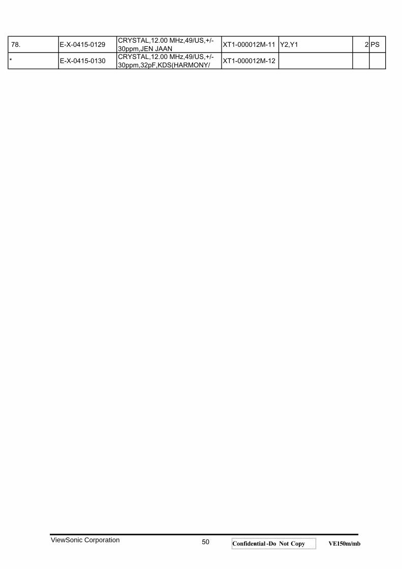
78. E-X-0415-0129CRYSTAL,12.00 MHz,49/US,+/-30ppm,JEN JAAN
XT1-000012M-11 Y2,Y1 2 PS
* E-X-0415-0130CRYSTAL,12.00 MHz,49/US,+/-30ppm,32pF,KDS(HARMONY/
XT1-000012M-12
ViewSonic Corporation 50 Confidential -- Do Not Copy VE150m/mb
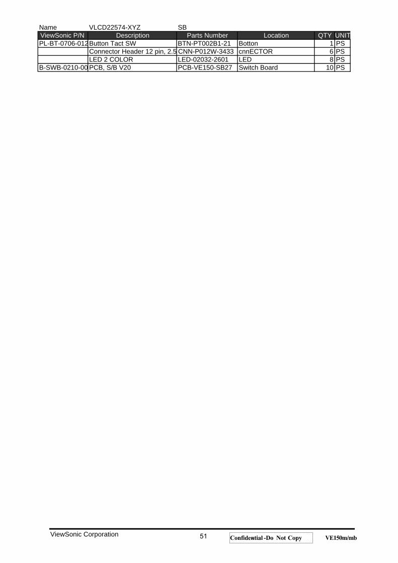
Name VLCD22574-XYZ SBViewSonic P/N Description Parts Number Location QTY UNITPL-BT-0706-012Button Tact SW BTN-PT002B1-21 Botton 1 PS
Connector Header 12 pin, 2.5 CNN-P012W-3433 cnnECTOR 6 PSLED 2 COLOR LED-02032-2601 LED 8 PS
B-SWB-0210-00 PCB, S/B V20 PCB-VE150-SB27 Switch Board 10 PS
ViewSonic Corporation 51 Confidential -- Do Not Copy VE150m/mb
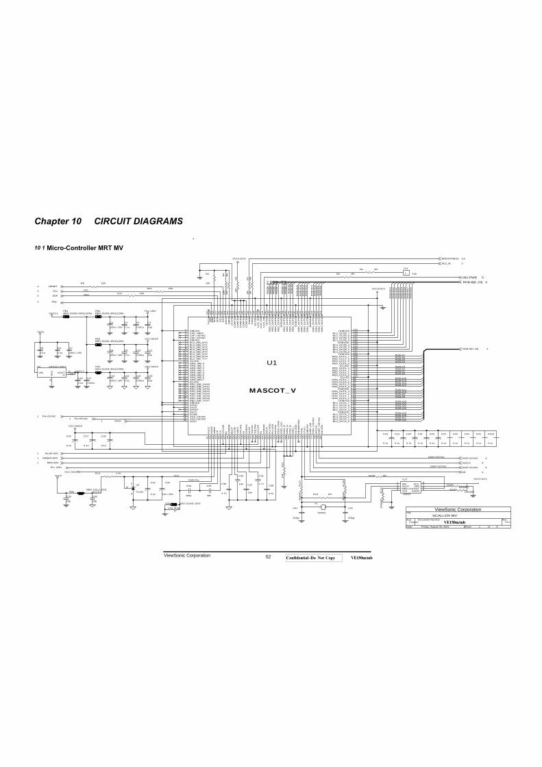
Chapter 10 CIRCUIT DIAGRAMS
10
.
1 Micro-Controller MRT MV
RG
B-B
12
C20
0.1u
RGB-A12
C12
100u / 16V
R12
10K
RGB-A14
RGB-A17
C28
0.1u
IRQ-3
INV-PWR 5R
GB
-B
4
RGB-A10
SDA
C42
22p
C34
150p
ADJ_IN 3
R1 0R
PA-HSYNC1
GND-PLL
R5
10K
R13 2.2K
R4
10K
R2
10k
RG
B-B
8
RG
B-B
0
PLL-VDD
RG
B-B
15SDA3 R
GB
-B13
C10
0.001u
R9 150
VCC-ADCP
C41
22p
R12
80R
(NP
)
R6
10K
RGB-A15
RG
B-B
20
C21
0.1u
VCC3-DCV
VCC5
C13
0.1u
C31
4.7n
RG
B-B
3
DE 4
RG
B-B
16RGB-A20
VCC3-2
R8
0R
RGB-A6
C29
0.1u
RG
B-B
18RGB-A23
C19
0.1u
C11
10p
RG
B-B
9
VCC5-4
GREEN-ADC1
RGB-A5
R3 0R
C8
100u / 16V
C26
0.1u
U1
MASCOT_V
123456789
101112131415
171819202122232425262728293031323334353637383940
41 42 43 44 45 46 47 48 49 50 51 52 53 54 55 56 57 58 59 60 61 62 63 64 65 66 67 68 69 70 71 72 73 74 75 76 77 78 79 80
12011911811711611511411311211111010910810710610510410310210110099989796959493929190898887868584838281
160
159
158
157
156
155
154
153
152
151
150
149
148
147
146
145
144
143
142
141
140
139
138
137
136
135
134
133
132
131
130
129
128
127
126
125
124
123
122
121
16
DIBVDDCAP_HREFCAP_HSYNCCAP_VSYNCDIBVSSBLU_INB_0/Y0BLU_INB_1/Y1BLU_INB_2/Y2BLU_INB_3/Y3BLU_INB_4/Y4BLU_INB_5/Y5BLU_INB_6/Y6BLU_INB_7/Y7DCVDDGRN_INB_0
GRN_INB_2GRN_INB_3GRN_INB_4GRN_INB_5GRN_INB_6GRN_INB_7DCVSSRED_INB_0/UV0RED_INB_1/UV1RED_INB_2/UV2RED_INB_3/UV3RED_INB_4/UV4RED_INB_5/UV5RED_INB_6/UV6RED_INB_7/UV7DIBVDDDVDDDVSSDTESTDVCCDGNDVGA_VSYNCVGA_HSYNCSOGI
AV
CC
AG
ND
VR
EF
CP
CZ
VC
CA
BB
IG
ND
AB
BC
LPV
TO
PV
BO
TV
CC
AG
GI
GN
DA
GG
CLP
TO
UT
PT
OU
TM
VC
CA
RR
IG
ND
AR
RC
LPP
LLV
DD
PLL
VS
SD
CV
SS
OS
D_F
SW
OS
D_C
LKO
SD
_RO
SD
_GO
SD
_BO
SD
_ID
CV
DD
RE
SE
RV
ED
XT
AL
XT
ALI
DIB
VS
SD
ISP
_DE
DIS
P_V
SY
NC
SH
CLK
DIS
P_H
SY
NC
DC
VS
S
DOBVSSBLU_OUTB_7BLU_OUTB_6BLU_OUTB_5BLU_OUTB_4
DOBVDDBLU_OUTB_3BLU_OUTB_2BLU_OUTB_1BLU_OUTB_0
DOBVSSRED_OUTA_7RED_OUTA_6RED_OUTA_5RED_OUTA_4
DCVDDRED_OUTA_3RED_OUTA_2RED_OUTA_1RED_OUTA_0
DCVSSGRN_OUTA_7GRN_OUTA_6GRN_OUTA_5GRN_OUTA_4
DOBVDDGRN_OUTA_3GRN_OUTA_2GRN_OUTA_1GRN_OUTA_0
DOBVSSBLU_OUTA_7BLU_OUTA_6BLU_OUTA_5BLU_OUTA_4
DOBVDDBLU_OUTA_3BLU_OUTA_2BLU_OUTA_1BLU_OUTA_0
TV
CLK
IRQ
SC
SS
DA
SC
LR
ST
GP
IO1
GB
IO0
DC
VS
SC
ON
FIG
4C
ON
FIG
3C
ON
FIG
2C
ON
FIG
1C
ON
FIG
0P
WM
0P
WM
1D
CV
DD
LCD
_VE
ELC
D_V
DD
LCD
_VB
LD
CV
SS
RE
D_O
UT
B_7
RE
D_O
UT
B_6
RE
D_O
UT
B_5
RE
D_O
UT
B_4
DO
BV
DD
RE
D_O
UT
B_3
RE
D_O
UT
B_2
RE
D_O
UT
B_1
RE
D_O
UT
B_0
DO
BV
SS
GR
N_O
UT
B_7
GR
N_O
UT
B_6
GR
N_O
UT
B_5
GR
N_O
UT
B_4
DO
BV
DD
GR
N_O
UT
B_3
GR
N_O
UT
B_2
GR
N_O
UT
B_1
GR
N_O
UT
B_0
GRN_INB_1
DISP-VSYNC 4
R12
70R
(NP
)
C35
39n
RG
B-B
17
RGB-A0
C17
0.001u
FB5BED-121L1-1001
VCC3-DCV
SCL
RED-ADC1
R13
110
K(N
P)
RG
B-B
23
FB1BED-151M1-3501(1206)
C16
0.1u
C5
0.1u
C1
100u / 16V
C36
4.7n
RG
B-B
5
BRIGHTNESS 3,5
RGB-A13
C22
0.1u
R11 150
U17
P2027
1234 5
678XIN
XOUTMRAVSS SSON
CLKOUTSR0VCCC37
10n
VCC3-DCV
RGB-A22
RGB-A3
RG
B-B
7
BLUE-ADC1
RGB-A16
RGB-A21
C2
0.1u
DISP-HSYNC
RGB-A8
RG
B-B
22
RG
B-B
6
C25
0.1u
FB6 BED-121M1-1002
R12910K(NP)
C43 3p
RG
B-B
1
C229
0.1u
RGB-A19
SHCLK 4
C9
0.1u
C6
0.1u
TP1
T401
RG
B-B
19
C27
0.1u
C32
0.1u
R126 0R
V0.1
SCALLER MV
Custom
1 6Friday, August 09, 2002
Title
Size Document Number Rev
Date: Sheet of
RGB-B[0..23] 4
FB3BED-151M1-3501(1206)
C39
33p
RG
B-B
21
U3
TL431
AC
R
DISP-HSYNC 4
RGB-A11
C33
10u / 25V
VCC-ADCP
VCC3-1
PA-VSYNC1
Vref
Y1
12MHZ
RG
B-B
2
R14 1M
VCC-ADCA
RGB-A[0..23] 4
C30
10n
C23
0.1u
RGB-A9
C24
0.1u
U2 AIC1117-33CY
G
OITAB
AD
J VOUTVINO
RESET3
RGB-A4
C15
10p
RGB-A18
C4
10p
FB2BED-151M1-3501(1206)
FB4BED-151M1-3501(1206)
R7
0R
VCC-ADCA
PLL-VDD
RGB-A1RGB-A2
C18
0.1u
C38
4.7n
VCC5
R13010K(NP)
R10 150
DISP-VSYNC
RG
B-B
11
RGB-A7
RG
B-B
10
C7
100u / 16V
SCL3
C14
0.001u
SOGI1
RG
B-B
14
C40
10p
C3
0.001u
ViewSonic Corporation 52 Confidential -- Do Not Copy VE150m/mb
ViewSonic Corporation
VE150m/mb
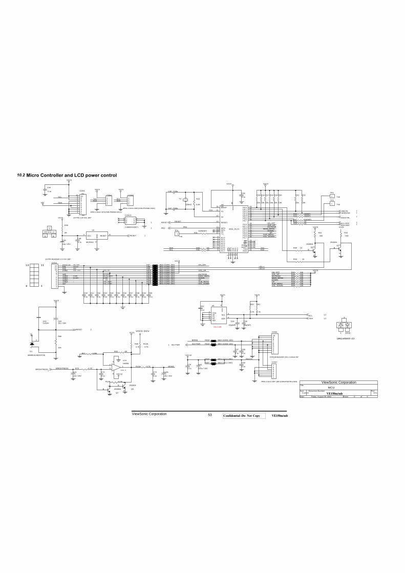
Micro Controller and LCD power control
C67
0.1u
LED-Y
SCL
MUTESW
U4
8051_PLCC
35
21
20
10
14151617
23456789
4342414039383736
2425262728293031
191832331311
44221 12 34 23
EA/VP
X1
X2
RESET
INT0INT1T0T1
P1.0P1.1P1.2P1.3P1.4P1.5P1.6P1.7
P0.0P0.1P0.2P0.3P0.4P0.5P0.6P0.7
P2.0P2.1P2.2P2.3P2.4P2.5P2.6P2.7
RDWR
PSENALE/P
TXDRXD
VC
CV
SS
INT2
INT3
P4.
0P
4.1
C48
0.1u
FB20 BED-121L1-2601
G
FB10 BED-102M1-1001
R54 10K
VCC5
VOL_UP
VCC5
INV-PWR
V0.1
MCU
Custom
2 6Friday, August 09, 2002
Title
Size Document Number Rev
Date: Sheet of
C53
0.1u
TxD
IRQ-
R68 5K
XXX
VCC12
CON2
4PIN 2.0mm 90"(CNN-P004W-2411)
1234
FB7 BED-102M1-1001
C60
0.1u
R16
10K
R31100K(NP)
VCC5
R32330
R134 4.7K
R56 10K
C52
0.1u
AMUTE 7
FB14 BED-102M1-1001
R29 33
ON_OFF
R23
6.8K
SCL
RED
C73
0.1u
12
VCC5
R35 33
C70
0.1u
VOL_DOWN
R70 4.7K
VIN
RESET1
BRIGHTNESS7 SOP-8
VCC5
FB16 BED-102M1-1001
VOL_UP
CON13
2.0MM3X2(90")
1 23 45 6
DOWN
VCC5
MAIN_MENU
R
smfb3
SCL
R15
10K
R20
10K
C6310u / 25V
smfb1
FB17 BED-102M1-1001
TxD
DOWN
OSD OFF
power-sw
1
C51
0.1u
DOWN
BRINS
+
-
U7ALM358
3
21
84
R67 120K
IRQ-1
C72
0.1u
C58
0.1u
MCP810
VOL_DOWN
SDA-DDC 1
MUTESW
R34 33
BRINS
RIGHT
UP
TP4
T401
R28 33
Q2
2N3904
C
B
E
FB11 BED-102M1-1001
RESET 1
VOL_UP
RESETON_OFF
VCC5RESET 2
FB97 BED-121L1-2601
UP
R60
4.7K
CON5
CON10HEADER 2X5 2.54mm 90"
12345678910
V
led2
SUB_MENU
SCL-DDC 1
C64
20p(NP)
RxD
DOWN
C621u/10V
R17
10K
MAIN_MENUMUTESW
MAIN_MENU
R46 10K
3
VDDCTRL 7
smfb0
C71
10u / 25V
AIDEOSD 7
R36 1K
C57
0.1u
R19
10K
VOL_DOWN
VCC5
FB13 BED-102M1-1001
VCC12
VCC5
smfb2
CON4
12-PIN HEADER 2.0 mm 180"
123456789
101112
C68
0.1u
FB8 BED-102M1-1001
1
CLK
led1
VCC5
R48 10K
C50
0.1u
R30
0R
R25 33(NP)
U5
MCP810 G
RV
GN
D RESETVCC
VCC3-DCV
MMBD4148(SOT23)
D1
AN
C
C
FB12 BED-102M1-1001
U6
24LC16B
123
4
5
6
7
8
A0A1A2
VSS
SDA
SCL
WP
VC
C
DOWNR50 10K
C69
0.1u
-
BRIGHTNESS
SDA
C231
10u / 25V
UP
sw6
C47 15p
RxD
CON7
7PIN 2.0mm DIP 180"(CNN-P007W-2403)
1234567
LED-G
Y2
12MHZ
ON_OFF
2
C44
0.1u
R1384.7K
GREEN
SUB_MENU
Q5
2N3904
C
B
E
SDA
R58 10K
C61
0.1u
R33330
FB19 BED-102M1-1001
C56
0.1u
FB9 BED-102M1-1001
R139 4.7K
C54
0.1u
SDA
C55
0.1u
R21
10K
sw7
R24 33(NP)
SCL 1,2
R61
4.7K
C59
0.1u
MAIN_MENU
FB15 BED-102M1-1001
TP3
T401
ON/OFF
CX1
220u / 16V
MUTESW
C49
10u / 25V
R52 10K
SDA 1,2
UP
SUB_MENU
R22
10K
1N4148SOT-23
VCC5
CON3
4PIN 2.0mm 180"(CNN-P004W-2411)
1234
+
Q1
2N3904
C
B
E
C46
0.1u
R43 1K
R59 10K
INV12V
FB18 BED-102M1-1001
C65
20p(NP)
INV-PWR1
VOL_UP
Q7
2N3904
C
B
E
VOL_DOWN
R694.7K
VCC5
smfb4
C45 15p
R66
10K
R18
10K
11
VCC5
SUB_MENU
CON1
10-PIN 2.00 mm 180"
12345
109876
12345
109876
R27 510(NP)
VCC5
TP2
T401
10.2
ViewSonic Corporation 53 Confidential -- Do Not Copy VE150m/mb
ViewSonic Corporation
VE150m/mb
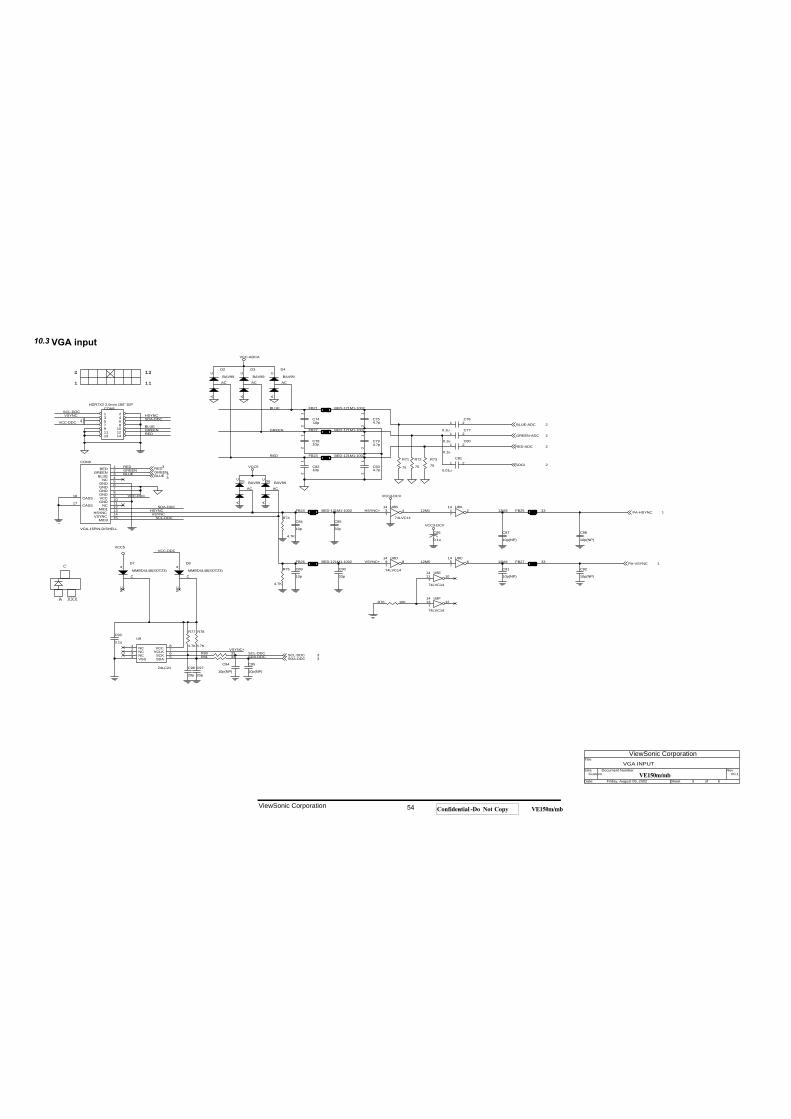
VGA input
GREEN
C7410p
12
R75
4.7K
BAV99
D3
AC
AC
VCC3-DCV
SCL-DDC 3
SCL-DDC
MMBD4148(SOT23)
D8
AN
C
C
U8D
74LVC14
9 814
7
BAV99
D4
AC
AC
SCL-DDC
VSYNC+
VCC-DDC
HSYNC
11
R78
4.7K
CON8HDR7X2 2.0mm 180" DIP
1 23 45 67 89 1011 1213 14
R73
75
1
FB27 33
R71
75
BLUE-ADC 2
RED
U8E
74LVC14
11 1014
7
R77
4.7K
C89
10p
CC92
10p(NP)
BAV99D6
AC
AC
V0.1
VGA INPUT
Custom
3 6Friday, August 09, 2002
Title
Size Document Number Rev
Date: Sheet of
C97
20p
BLUE 3
BAV99D5
AC
AC
R81 33
12M4
C754.7p
12
R80 33
RED-ADC 2C80
0.1u
1 2
U9
24LC21
1234 5
678NC
NCNCVSS SDA
SCKVCLKVCC
VCC5
FB23 BED-121M1-1002
RED
12M5
PA-HSYNC 1
C94
10p(NP)
C76
0.1u
1 2
U8B
74LVC14
3 414
7
BLUE
FB26 BED-121M1-1002
C85
33p
2
C84
10p
VCC-DDC
12M2VSYNC
SOGI 2C834.7p
12
GREENGREEN-ADC 2
FB25 33
C794.7p
12
U8A1 2
14
7
BLUE
SDA-DDC
C86
0.1u
R74
4.7K
12
VSYNC+
C77
0.1u
1 2
C81
0.01u
1 2
12M1
C87
10p(NP)
GREEN3
PA-VSYNC 1
VSYNC
R76 10K
FB21 BED-121M1-1002
VCC5
C88
10p(NP)
A
BAV99
D2
AC
AC
VCC3-DCV
VCC-DDC
C95
10p(NP)
C7810p
12
SDA-DDC 3
GREEN
SDA-DDC
C90
33p
FB24 BED-121M1-1002
R72
75
HSYNC+
U8F
74LVC14
13 1214
7
RED3
RED
FB22 BED-121M1-1002
HSYNC
VCC-ADCA
C96
20p
SDA-DDC
C93
0.1u
BLUE
CON9
VGA-15PIN-D/SHELL
123456789101112131415
16
17
REDGREEN
BLUENC
GNDGNDGNDGNDVCCGND
NCMID1
HSYNCVSYNC
MID3
CASS
CASS
C8210p
12
XXX
SCL-DDC
U8C5 6
14
7C91
10p(NP)MMBD4148(SOT23)
D7
AN
C
C
10.3
ViewSonic Corporation 54 Confidential -- Do Not Copy VE150m/mb
ViewSonic Corporation
VE150m/mb
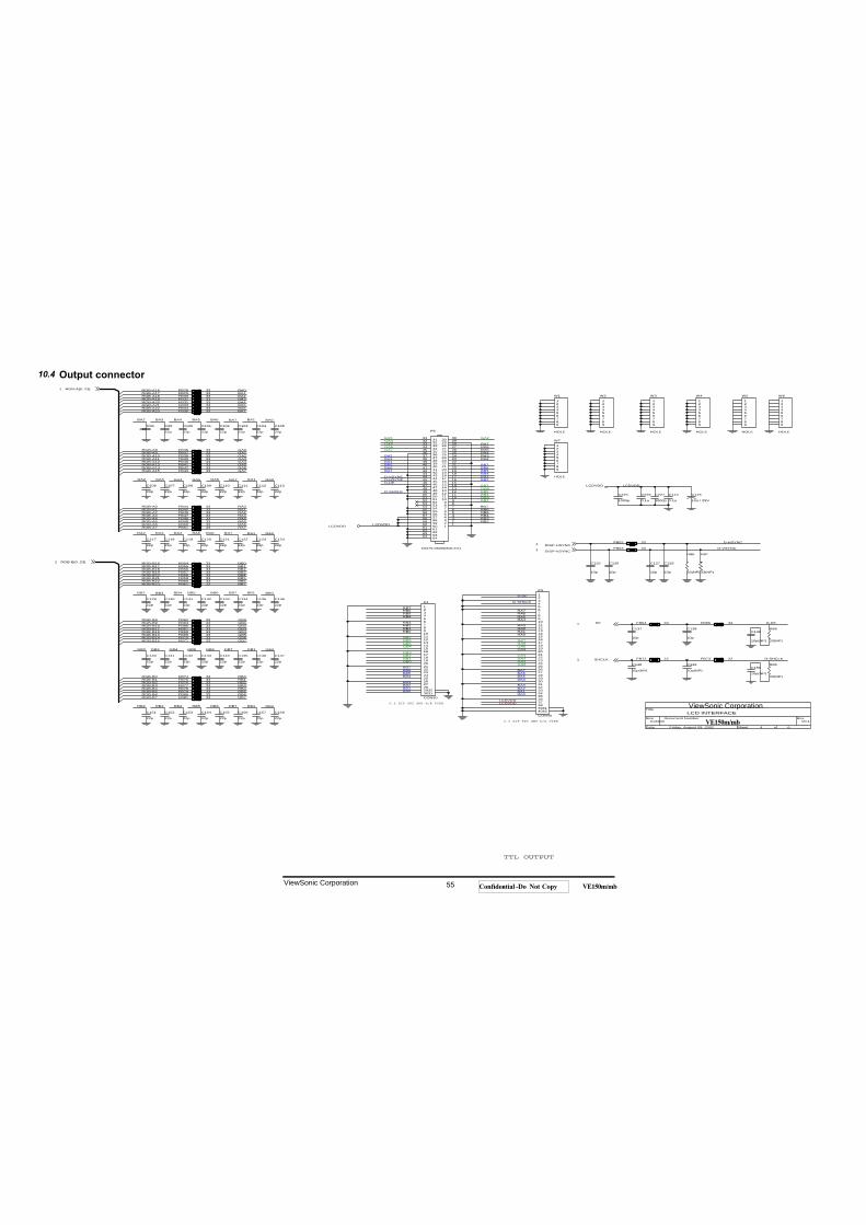
Output connector
FB78 33
GB4GB3
RB4
GA6
RGB-A11
RB7
C155
22p
C157
22p
GB3
RB6
GB2
BA4
BA2
GB6
GB0
C124
22p
FB44 33
RB3
RB5
GA7FB70 33
C110
22p
RB2
RGB-B8
GA4
FB66 33
C131
22p
RA4
RB5
GA6
BA2
GA6
RGB-A6
BB2
RGB-A22
BB0
BB7
GB7
C227
1000p
FB69 33
C101
22p
BB5
FB28 33
GA5
RB6
W1
HOLE
123456789
C111
22p
GA3
RGB-A5
RGB-A13
RA2
FB62 33
RA2
GA6
BB3
GA4
GA1
FB65 33
FB54 33
C103
22p
GA0
RGB-A15
RGB-A0
C151
22p
GB6
RA0
BB7
GB6
C156
22p
C141
22p
RGB-B9
BA2
BA7
DE1
RGB-B0
D-SHCLK
FB47 33 RB4
BA5
GB0
RGB-B10
GB7
FB63 33
GB7
FB77 33
V0.1
LCD INTERFACE
Custom
4 6Friday, August 09, 2002
Title
Size Document Number Rev
Date: Sheet of
RA2
RA4
RA7
RGB-A9
RGB-A3
BA3
P3
CON40
1234567891011121314151617181920212223242526272829303132333435363738394042
41
RGB-B13
RGB-B23
W6
HOLE
123456789
FB71 33
RA3
BA0
FB58 33
C125
10p
0.5 ZIF FPC SMT R/A TYPE
C107
22p
C136
22p
FB39 33
GB5
RGB-A2
C132
22p
GB4
BB2
RGB-B1BA5
RB3
FB59 33
TTL OUTPUT
GA7BB6
RGB-B22
RGB-A23
RGB-A12
GA0
RB4
D-DE
BA1
BB1
BA1
BB4
FB37 33
D-HSYNC
RGB-A18
RGB-A1
RA0
BB6
FB76 33
BB4
D-SHCLK
GA7
R87
33(NP)
FB79 33
RB7
FB64 33
FB73 22
C117
22p
RB0
BA0
RA0
FB42 33
RA7RGB-A7
FB72 22
R88
33(NP)
RB0
D-SHCLK
D-DE
FB33 33
C104
22p
BB6
FB55 33
C121
22p
W7
HOLE
123456789
GA1
LCDVDD
FB29 33
C139
10p(NP)
C129
22p
FB35 33
0.5 ZIF FPC SMT R/A TYPE
LCDVDD
FB36 33
FB48 33
BA3
GA5
C116
10u / 25V
C134
22p
C99
22p
LCDVDD
GB2
RB6
GA2
RGB-B4
C114
0.1u
C148
10p(NP)
FB51 33
C109
22p
GA4
C130
22p
RB5
RB1
C118
22p
RGB-B5
GA3
C137
10p
RGB-B20
RGB-A8
RGB-B17
GA2
GB5
BB1
P4
CON30
12345678910111213141516171819202122232425262728293031
32RB5
BA5
BA4
BB0
RB3
DISP-HSYNC1
RA2
C112
22pC226
0.1u
FB40 33
BB5BB3
BA3
GB2
BB4
BA6
RGB-A10
BB6
RGB-B11
RA1
GB6 GB1
BB3
BA7
FB30 33
FB49 33
GB4
BB0
GB3
D-HSYNC
GA1
C135
22p
R86
33(NP)
C126
10p
RGB-B12
RA4
BA0
W5
HOLE
123456789
FB57 33
C108
22p
BB2
C142
22p
BB2
RA3
BB1
FB81 33
GA2
RGB-A14
BA1
C113
22p
GB7
W3
HOLE
123456789
GB5
BB4
LCDVDD
FB67 33
C154
22p
W2
HOLE
123456789
C146
22p
GA2
BA6
RA1
FB52 33
C102
22p
RA3
GB4
GA3
D-DE
C149
10p(NP)
RGB-B14GB5
RGB-A21
C105
22p
RGB-B18
GB0
GA0
C145
22p
FB41 33
C225
1000p
C122
22p
RGB-A20
RA3
C127
10p
RB6
BB7
C9822p
C120
22p
FB46 33
C143
22p
FB61 33
D-VSYNC
C153
22p
RGB-A19
FB74 33
RGB-A17
C119
22p
RA6
RGB-A16
RA7
RGB-B21
BA5
RB2
R89
33(NP)
RGB-B3
BB5
GB3
C133
22p
FB56 33
C140
22p
RGB-B19
FB38 33
FB80 33
RGB-A4
FB31 33
RGB-B16
RB0
RA4
C106
22p
RA6RA5
BB5
LCDVDD
C138
10p
C152
22p
RGB-B2
RA6
GA7
BB3
GA5
RGB-B7
RA5
BA3
RA7
P5
53475-0600(MOLEX)
876
12345
109
111213
1514
1716
18
2019
30292827262524232221
3534333231
4039383736
6059585756555453525150494847464544434241
61626364
876
12345
109
111213
1514
1716
18
2019
30292827262524232221
3534333231
4039383736
6059585756555453525150494847464544434241
61626364
SHCLK1
GA4
FB68 33
DISP-VSYNC1
BA6
FB45 33
FB32 33
C100
22p
FB34 33
RB1
GB2
GA3
C158
22p
FB60 33
RGB-B15
RGB-B6
BA6
BA4
RB2
RB7
C128
10p
RA5
FB43 33
RB2
RGB-B[0..23]1
RA5
RA1
RB7
RGB-A[0..23]1
RA6
BB7
C123
22p
C147
22p
BA7
RB4
C150
10p(NP)
FB53 33 D-VSYNC
BA2
BA4
BA7
GB1
RB1
GB1
W4
HOLE
123456789
RB3
LCDVDD
C144
22p
FB50 33
GA5
FB75 33
10.4
ViewSonic Corporation 55 Confidential -- Do Not Copy VE150m/mb
ViewSonic Corporation
VE150m/mb
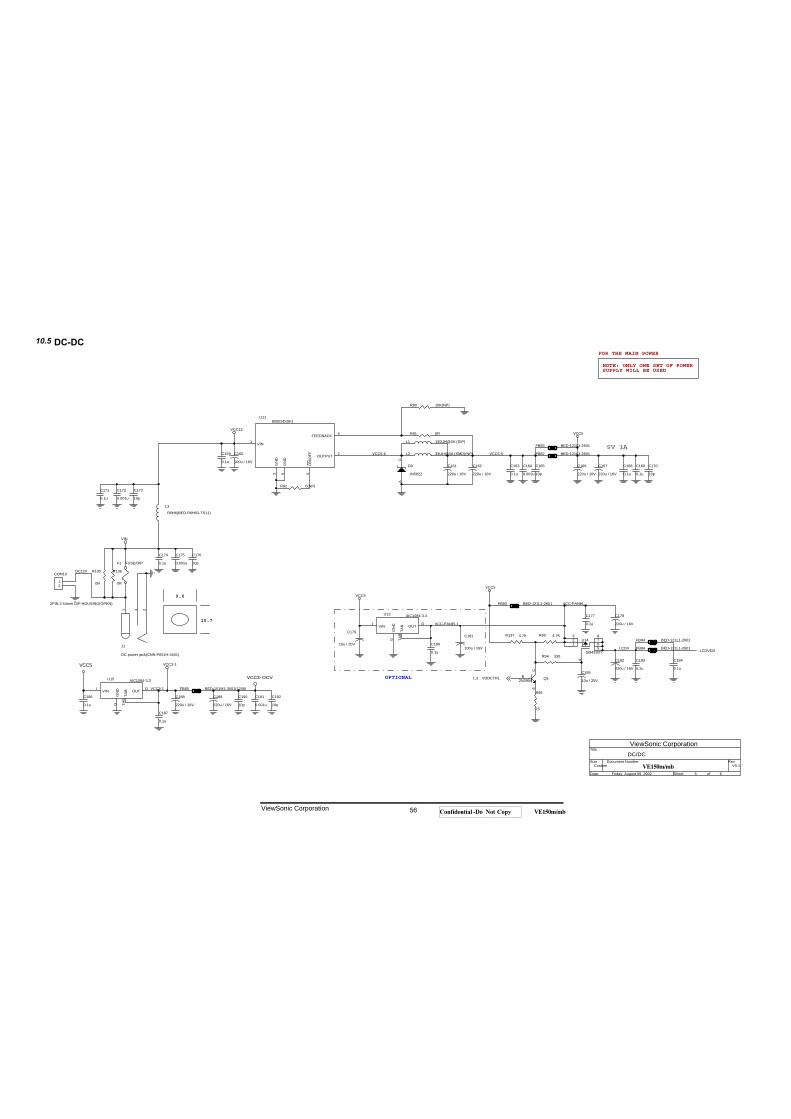
DC-DC
R93 4.7K
FB82 BED-121L1-2601
C174
0.1u
VCC3-1
CON10
2PIN 2.54mm DIP HOUSING(OPEN)
12
VCC5
FB83 BED-121L1-2601
R91 0R
C181
100u / 16V
NOTE: ONLY ONE SET OF POWERSUPPLY WILL BE USED
LCDV
C170
10p
L2 33UH@3A (SMD)(NP)
C185
10u / 25V
C160
100u / 16V
R90 10K(NP)
Q42N3904
C
B
E
FB93 BED-121L1-2601
VCC3-1
LCDVDD
C163
0.1u
C183
0.1u
9.0
C191
0.001u
C186
0.1u
C184
0.1u
VCC5-5
VCC-PANEL
C173
10p
C159
0.1u
VCC5
J1
DC power jack(CNN-P001H-3401)
1 3 2
C182
220u / 16V
D9
IN5822
AC
10.7
R135
0R
R136
0R
VCC5-6
C168
0.1u
FB84 BED-121L1-2601
FOR THE MAIN POWER
C188
220u / 16V
U15 AIC1084-3.3
I
G
O
TAB
VIN
GN
D OUT
TAB
VCC12
U118050SD(SK)
1
3 5
2
4
6
VIN
GN
D
ON
/OFF OUTPUT
FEEDBACK
GN
D
C172
0.001u
C161
220u / 16V
C166
220u / 16V
C162
220u / 16V
R137 4.7K
C190
10p
L1 150UH@3A (DIP)
L3R6H6(BED-R6H63-TS11)
VCC3-DCV
VCC5
R95
75
VCC-PANEL1
C189
220u / 16V
C169
0.1u
C164
0.001u
U13 AIC1084-3.3
I
G
O
TAB
VIN
GN
D OUT
TAB
DC12V
V0.1
DC/DC
Custom
5 6Friday, August 09, 2002
Title
Size Document Number Rev
Date: Sheet of
FB94 BED-121L1-2601
VCC5
VIN
OPTIONAL
C175
0.001u
VDDCTRL1,3
FB85 BED-151M1-3501(1206)
C180
0.1u
C177
0.1u
C192
10p
C179
10u / 25VU14
Si9433DY
4
6
372
1
8
5
C176
10p
C167
220u / 16V
R94 330
C171
0.1u
C178
220u / 16V
C165
10p
F1 FUSE/DIP
5V 3A
C187
0.1u
R92 0(NP)
10.5
ViewSonic Corporation 56 Confidential -- Do Not Copy VE150m/mb
ViewSonic Corporation
VE150m/mb
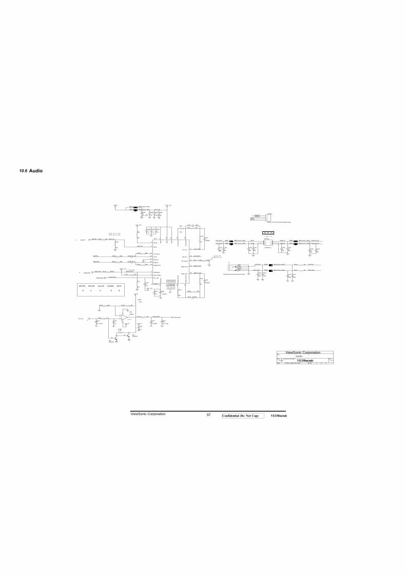
Audio
C214
180p
R1234.7K
1
C200
0.1u
0
C219 100p
Left-M
AIDEOSDAIDEOSD3
R97 33K
6
SDWN
R96
20K
R106 20K
C199
0.1u
Left-Out-M
RIGHT-IN
C222
0.1u
R115 10KC213
180p
FB86 BED-121L1-2601
MODE
C232
10u / 25V
MUTE
AIDEOADJ
Left-P
Right-P
C223
0.1u(NP)
C204
33p
R99
10K
VCC_AU
2
J2
PHONEJACK(CNN-P001H-3402)
3C10J11K2B1A
0
Right-M
C215
180p
C212
180p
Left-Out-P
R124 0R
R107 20K
Q82N3904
C
B
E
MODE VCC OP VOL
AMUTE3
Left-out-M
R117
10K
C203
33pC208
33p
R108 100K
FB91 BED-121L1-2601
AIDEOSD1
C194
0.1u
Right-out-M
C206
33p
R119
20K
U16
APA4835A
1 8 14 20 23
6 16 27
2
3
4
5
7
9
10
11
12
13
28
26
252422
21
19 18
17
15
29
GN
DG
ND
GN
DG
ND
GN
D
VD
D
VD
D
VD
D
Shutdown
Gain Select
Mode
Mute
DC_Vol
Right Dock
Right In
Beep In
Lift In
Left Dock
Right Out+
Right Out-
Rig
ht G
ain2
Rig
ht G
ain1
Byp
ass
HP Sense
Lift
Gai
n1
Lift
Gai
n2
Lift out -
Lift out +
GN
D
Left-Out-P
C218
1u/50V
12
C209
33p
Right-Out-P
0
FB87 BED-121L1-2601
R100
0R
C205
33p
C210 0.1u
CON12
4PIN 2.0mm 90"(CNN-P004W-2411)
1234
C202
33p
R120 33K
LEFT-IN R112 1K
C198
0.1u
+
-
U7BLM358
5
67
84
LEFTIN
C193
10u / 25V
12
VCC12
AMUTE1C207
33p
HPS
VCC_AU
AIDEOADJ
R1404.7K
C228
0.1u
AMUTE
Left-M
R122 5K
VCC_AU
C196
10p
Left-P
RIGHTIN
FB88 BED-121L1-2601
1
ADJ_IN3
FB92 BED-121L1-2601
C195
0.001u
C221
10u / 25V
R111 20K
MODE GND OP MAX
VCC_AU
Q62N3904
C
B
E
V0.1
AUDIO
Custom
6 6Friday, August 09, 2002
Title
Size Document Number Rev
Date: Sheet of
R114 0(NP)
R101 0R
C211 0.1u
Right-out-M
AIDEOADJ
R121 10K
RIGHTIN
R109 20K
VCC12
HI HP OUT
VCC5
FB90 BED-121L1-2601
R125 4.7K
R116
0R
LOW SP OUT
1 5
VCC5
Right-M
C201
0.068uF
C217
0.1u
Right-Out-P
C230
0.1u
FB89 BED-121L1-2601
R113 1K
FB95 BED-121L1-2601
VCC_AU
AMUTE1
LEFTIN
CON11
2.5MM3X2
123456
C197 100p
SOP-8
Right-P
AIDEOADJ
C216
0.068uF
HI SHUTDOWN
R102
10K
HPS
GAIN
2.0MM 3X2
10.6
ViewSonic Corporation 57 Confidential -- Do Not Copy VE150m/mb
ViewSonic Corporation
VE150m/mb
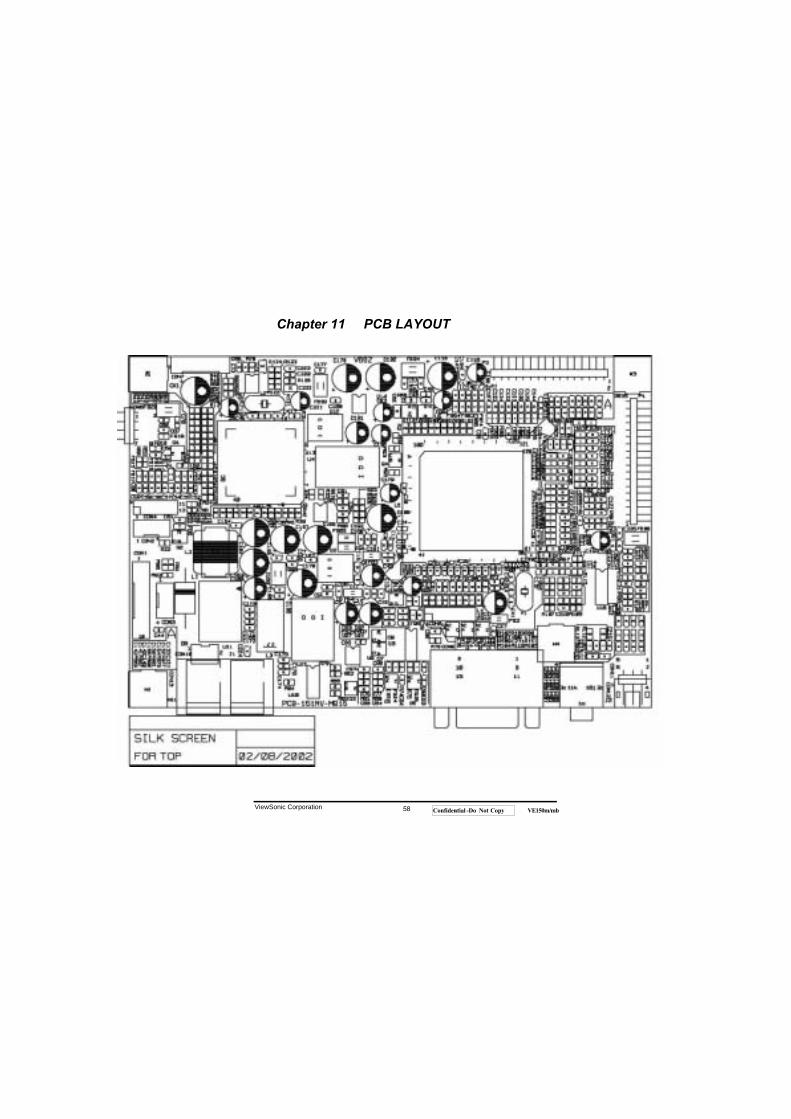
ViewSonic Corporation 58 Confidential -- Do Not Copy VE150m/mb
Chapter 11 PCB LAYOUT
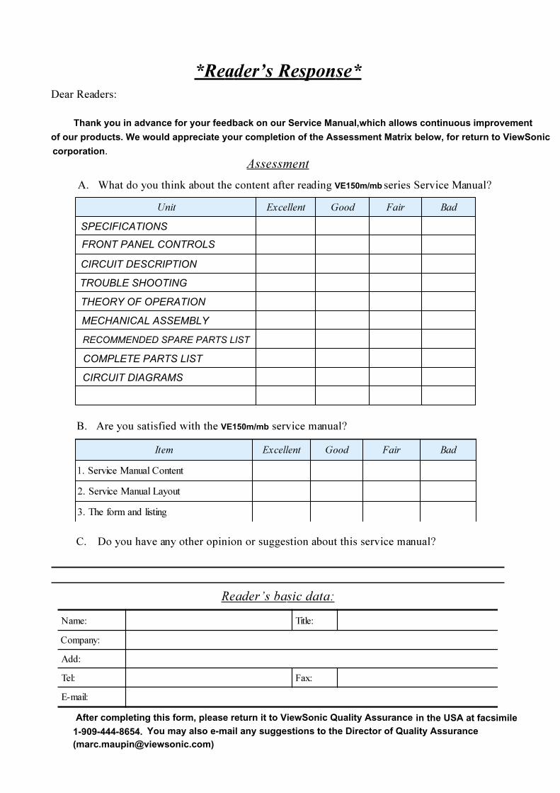
�����������������������������
Thank you in advance for your feedback on our Service Manual,which allows continuous improvement
of our products. We would appreciate your completion of the Assessment Matrix below, for return to ViewSonic
corporation����������
�� ���� ����������������������VE150m/mb����������������
����������� ���������� �������������������������������������������������������
������� ���������
���������After completing this form, please return it to ViewSonic Quality Assurance
������������ ������� ���������������������������������VE150m/mb��������!�������"������
���# ����$
������
���
��$ %�&
����'(
���� ��������� ��� ��� ��
������������"������!)
��� �*�����"������!+
����������������$,
���� ��������� ��� ��� ��
������ in the USA at facsimile 1-909-444-8654. You may also e-mail any suggestions to the Director of Quality Assurance ([email protected])
SPECIFICATIONS
FRONT PANEL CONTROLS
CIRCUIT DESCRIPTION
TROUBLE SHOOTING
THEORY OF OPERATION
MECHANICAL ASSEMBLY
RECOMMENDED SPARE PARTS LIST
COMPLETE PARTS LIST
CIRCUIT DIAGRAMS