Embed Size (px)
Citation preview

SetPoint 511s and 512 ControllersInstallation and Operation Manual
SetPoint 512
SetPoint 511s
Setpoint 511s and 512 ControllersInstallation and Operation Manualis published by Uponor Wirsbo, Inc.5925 148th Street WestApple Valley, MN 55124(952) 891-2000
© 2005 Uponor WirsboAll rights reserved
Second Edition, August 2005First Printing, November 2002Printed in the United States of America
1
Table
of
Conten
ts
Table of Contents
Table of Contents PageIntroduction..................................................................................1
Installation....................................................................................2
Getting Ready ........................................................................2
Removing the Front Cover....................................................2
Mounting the Base................................................................2
Rough-in Wiring......................................................................3
Wiring the Controller..............................................................3
Installing the Front Cover......................................................3
Wiring Examples....................................................................4
Display and Keypad Operation..............................................6
Cycles per Hour......................................................................6
Early Start................................................................................7
Optional Sensors....................................................................7
Access Levels ..............................................................................7
Sequence of Operation for the SetPoint 511s ....................8
Sequence of Operation for the SetPoint 512 (Two-stage Heat)....................................................................8
Sequence of Operation for the SetPoint 512 (Heat and Cool)......................................................................9
Programming ..................................................................................11
Navigating the Menus ........................................................11
Troubleshooting ....................................................................................16
Error Messages....................................................................16
Technical Data ............................................................................17
IntroductionThe SetPoint 511s and 512 Controllers are microprocessor-basedcontrols that sense the air temperature in a specific area andincrease the comfort level of that area as well as increase theenergy efficiency of the heating or cooling system.
2
Inst
all
ati
on
Installation
InstallationGetting ReadyCheck the contents of this package. If any contents listed beloware missing or damaged, please contact your Uponor Wirsbosales representative or distributor for assistance.
• SetPoint 511s (part number A3041511) includes oneprogrammable setpoint controller, one floor sensor (partnumber A3040079), an Installation and Operation Manualand a User Manual.
• SetPoint 512 (part number A3040512) includes oneprogrammable setpoint controller, an Installation andOperation Manual and a User Manual.
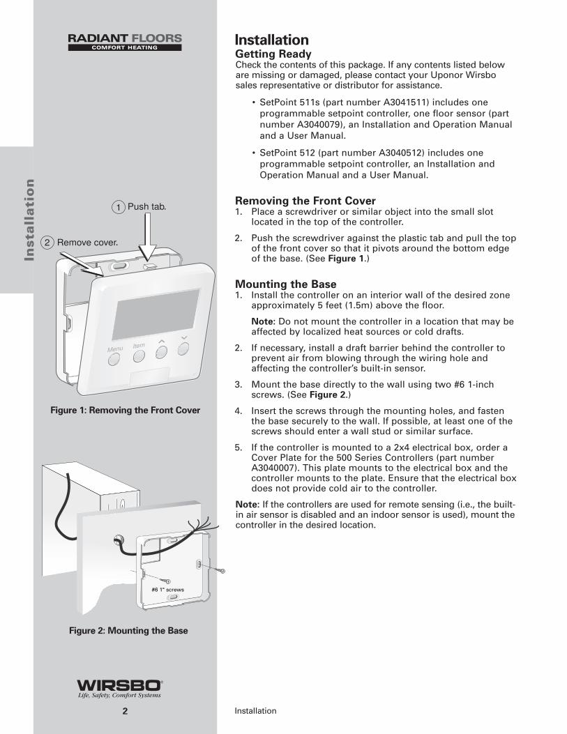
Removing the Front Cover1. Place a screwdriver or similar object into the small slot
located in the top of the controller.
2. Push the screwdriver against the plastic tab and pull the topof the front cover so that it pivots around the bottom edgeof the base. (See Figure 1.)
Mounting the Base1. Install the controller on an interior wall of the desired zone
approximately 5 feet (1.5m) above the floor.
Note: Do not mount the controller in a location that may beaffected by localized heat sources or cold drafts.
2. If necessary, install a draft barrier behind the controller toprevent air from blowing through the wiring hole andaffecting the controller’s built-in sensor.
3. Mount the base directly to the wall using two #6 1-inchscrews. (See Figure 2.)
4. Insert the screws through the mounting holes, and fastenthe base securely to the wall. If possible, at least one of thescrews should enter a wall stud or similar surface.
5. If the controller is mounted to a 2x4 electrical box, order aCover Plate for the 500 Series Controllers (part numberA3040007). This plate mounts to the electrical box and thecontroller mounts to the plate. Ensure that the electrical boxdoes not provide cold air to the controller.
Note: If the controllers are used for remote sensing (i.e., the built-in air sensor is disabled and an indoor sensor is used), mount thecontroller in the desired location.
.
.
#6 1" screws
Figure 1: Removing the Front Cover
Figure 2: Mounting the Base

Rough-in WiringNote: 18 AWG or similar wire is recommended for all 24VACwiring.
1. Strip all wires to ¹⁄₄" (6mm) to ensure proper connection tothe control.
2. Run wires from the 24VAC power to the controller. Use aclean power source to ensure proper operation.
3. If using an optional sensor, install the sensor according tothe appropriate installation sheet and run two wires fromthe sensor to the controller.
4. Run wires from the heating and cooling device to thecontroller.
Wiring the ControllerRefer to the wiring examples on pages 4 and 5 to properly wirethe controller.
1. Connect the 24VAC power to the R and C terminals on thecontroller. This connection provides power to themicroprocessor and display of the controller.
2. When wiring an optional sensor, connect the two wiresfrom the sensor to the Com and S1 terminals.
Note: The Heat terminals are isolated outputs. There is no poweravailable on these terminals from the controller. Use theseterminals as a switch for a 24VAC circuit. This circuit can operatea low-current, 24VAC device directly or an external relay toenable a line voltage or high-current device.
Note: The Heat 2/Cool terminals (SetPoint 512 only) are isolatedoutputs. No power is available on these terminals from thecontroller. This circuit can operate a low-current, 24VAC devicedirectly or an external relay to enable a line voltage or high-current device.
Installing the Front Cover1. Align the hinges on the bottom of the front cover with the
bottom of the controller mounting base.
2. Pivot the front cover around the bottom hinges and pushthe top against the mounting base until it snaps firmly inplace. (See Figure 3.)
3
Insta
llatio
n
Installation
Figure 3: Installing the Front Cover
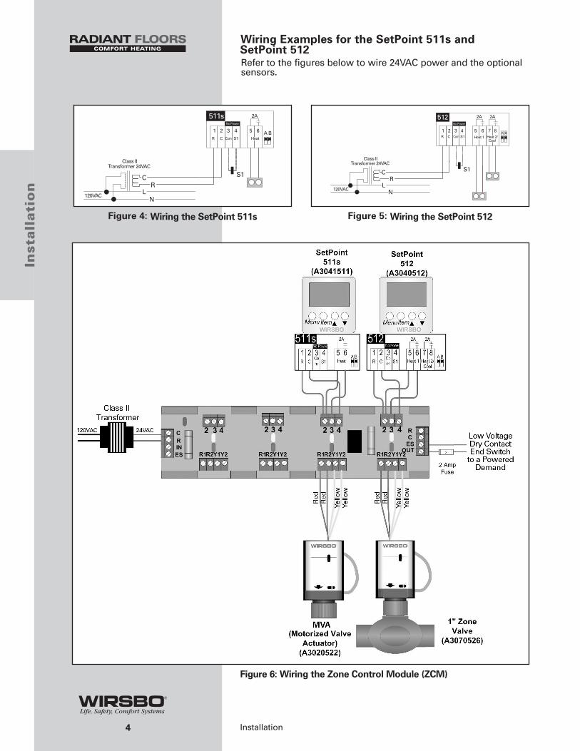
Wiring Examples for the SetPoint 511s and SetPoint 512Refer to the figures below to wire 24VAC power and the optionalsensors.
4
Inst
all
ati
on
Installation
R C Com S1 Heat
Class IITransformer 24VAC
Heat 1
Class IITransformer 24VAC
R C Com S1 Heat 2/Cool
Figure 4: Wiring the SetPoint 511s Figure 5: Wiring the SetPoint 512
Figure 6: Wiring the Zone Control Module (ZCM)
5Installation
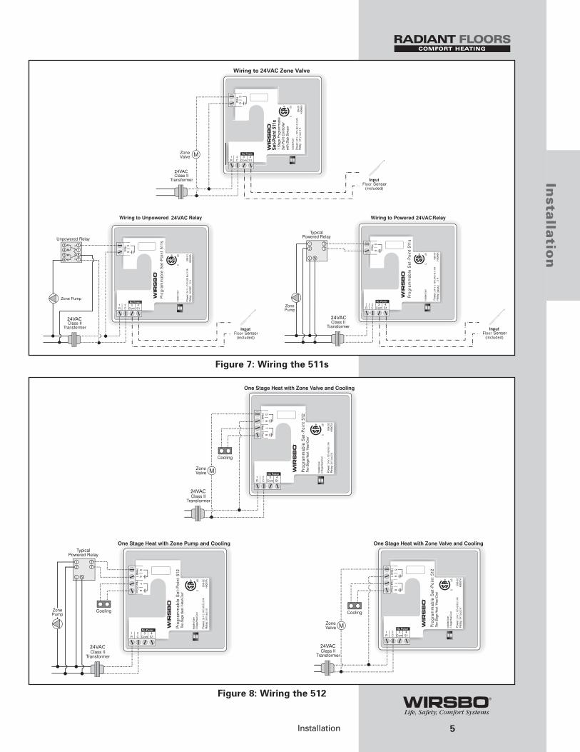
Wiring to 24VAC Zone Valve
24VAC
VAC
24VAC
24VA
C
24VAC
24VAC 24VAC
Insta
llatio
n
Figure 7: Wiring the 511s
Figure 8: Wiring the 512
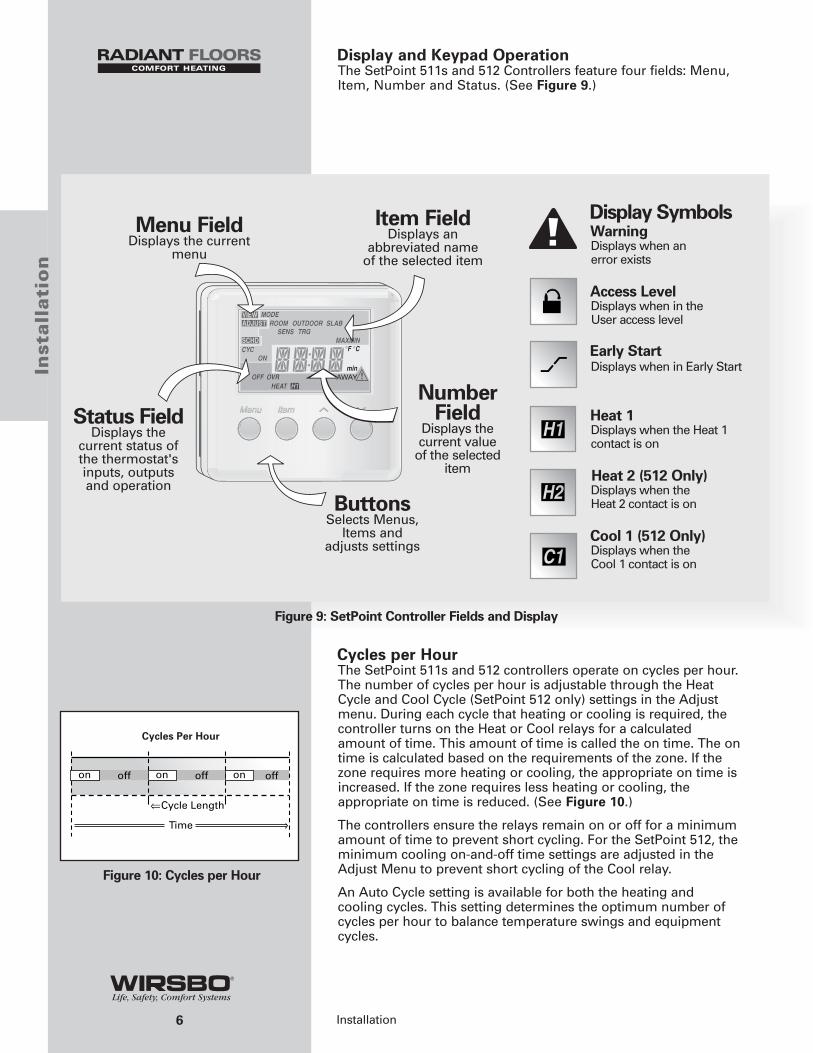
Display and Keypad OperationThe SetPoint 511s and 512 Controllers feature four fields: Menu,Item, Number and Status. (See Figure 9.)
Cycles per HourThe SetPoint 511s and 512 controllers operate on cycles per hour.The number of cycles per hour is adjustable through the HeatCycle and Cool Cycle (SetPoint 512 only) settings in the Adjustmenu. During each cycle that heating or cooling is required, thecontroller turns on the Heat or Cool relays for a calculatedamount of time. This amount of time is called the on time. The ontime is calculated based on the requirements of the zone. If thezone requires more heating or cooling, the appropriate on time isincreased. If the zone requires less heating or cooling, theappropriate on time is reduced. (See Figure 10.)
The controllers ensure the relays remain on or off for a minimumamount of time to prevent short cycling. For the SetPoint 512, theminimum cooling on-and-off time settings are adjusted in theAdjust Menu to prevent short cycling of the Cool relay.
An Auto Cycle setting is available for both the heating andcooling cycles. This setting determines the optimum number ofcycles per hour to balance temperature swings and equipmentcycles.
6
Inst
all
ati
on
Installation
Display SymbolsWarningDisplays when an error exists
Access Level Displays when in the User access level
Early Start Displays when in Early Start
Heat 1Displays when the Heat 1contact is on
Heat 2 (512 Only)Displays when the Heat 2 contact is on
Cool 1 (512 Only)Displays when the Cool 1 contact is on
ButtonsSelects Menus,
Items andadjusts settings
Status FieldDisplays the
current status ofthe thermostat'sinputs, outputsand operation
NumberField
Displays thecurrent value
of the selecteditem
Item FieldDisplays an
abbreviated nameof the selected item
Menu FieldDisplays the current
menu
Cycles Per Hour
Time
offoff offon onon
Figure 9: SetPoint Controller Fields and Display
Figure 10: Cycles per Hour
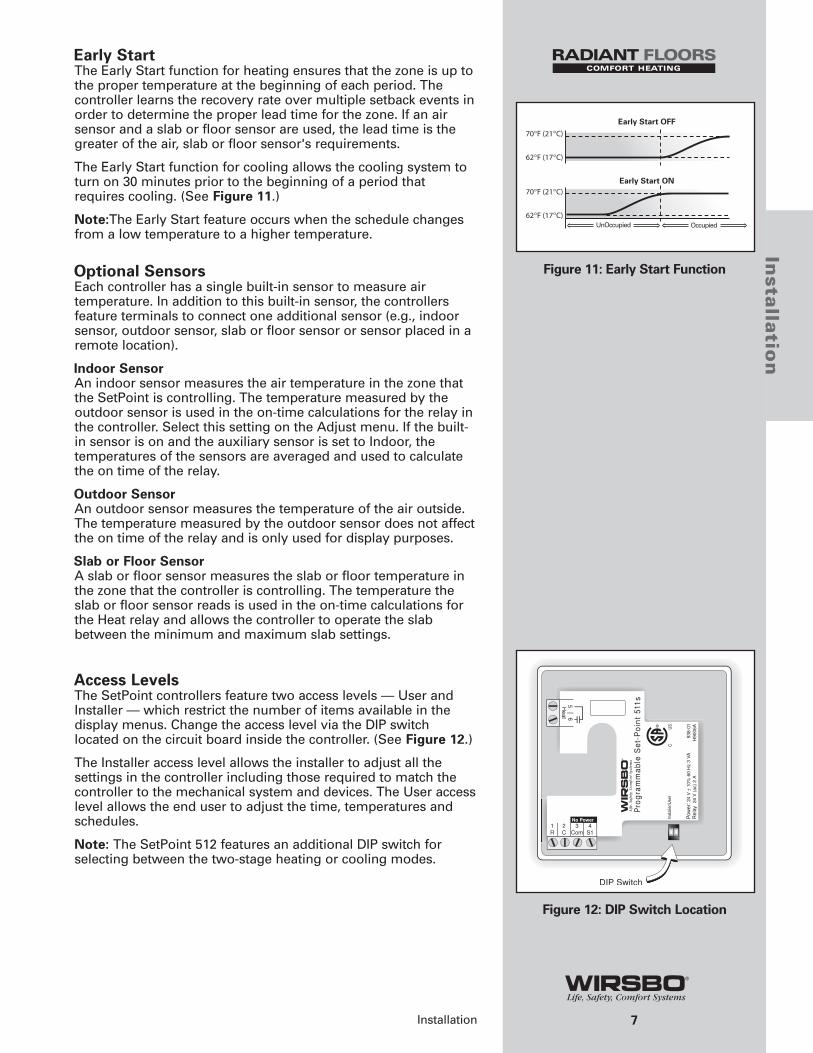
Early StartThe Early Start function for heating ensures that the zone is up tothe proper temperature at the beginning of each period. Thecontroller learns the recovery rate over multiple setback events inorder to determine the proper lead time for the zone. If an airsensor and a slab or floor sensor are used, the lead time is thegreater of the air, slab or floor sensor's requirements.
The Early Start function for cooling allows the cooling system toturn on 30 minutes prior to the beginning of a period thatrequires cooling. (See Figure 11.)
Note:The Early Start feature occurs when the schedule changesfrom a low temperature to a higher temperature.
Optional SensorsEach controller has a single built-in sensor to measure airtemperature. In addition to this built-in sensor, the controllersfeature terminals to connect one additional sensor (e.g., indoorsensor, outdoor sensor, slab or floor sensor or sensor placed in aremote location).
Indoor SensorAn indoor sensor measures the air temperature in the zone thatthe SetPoint is controlling. The temperature measured by theoutdoor sensor is used in the on-time calculations for the relay inthe controller. Select this setting on the Adjust menu. If the built-in sensor is on and the auxiliary sensor is set to Indoor, thetemperatures of the sensors are averaged and used to calculatethe on time of the relay.
Outdoor SensorAn outdoor sensor measures the temperature of the air outside.The temperature measured by the outdoor sensor does not affectthe on time of the relay and is only used for display purposes.
Slab or Floor SensorA slab or floor sensor measures the slab or floor temperature inthe zone that the controller is controlling. The temperature theslab or floor sensor reads is used in the on-time calculations forthe Heat relay and allows the controller to operate the slabbetween the minimum and maximum slab settings.
Access LevelsThe SetPoint controllers feature two access levels — User andInstaller — which restrict the number of items available in thedisplay menus. Change the access level via the DIP switchlocated on the circuit board inside the controller. (See Figure 12.)
The Installer access level allows the installer to adjust all thesettings in the controller including those required to match thecontroller to the mechanical system and devices. The User accesslevel allows the end user to adjust the time, temperatures andschedules.
Note: The SetPoint 512 features an additional DIP switch forselecting between the two-stage heating or cooling modes.
7
Insta
llatio
n
Installation
Figure 11: Early Start Function
Figure 12: DIP Switch Location
8
Inst
all
ati
on
Installation
Sequence of Operation for the SetPoint 511sAir Sensor Only OperationWhen operating with only an air sensor, the on time for the Heatrelay is calculated to satisfy the requirements of the air sensor.
Slab or Floor Sensor Only OperationWhen operating with only a slab or floor sensor, the on time forthe Heat relay is calculated to satisfy the requirements of the slabor floor sensor. The controller operates to maintain the slab at theminimum slab temperature setting.
Note: Using only a slab or floor sensor may cause overheating orunderheating of the space.
Air and Slab or Floor Sensor OperationWhen operating with both air and slab or floor sensors, thecontroller calculates an on time for the Heat relay to satisfy theslab or floor sensor’s requirements and an on time to satisfy theair sensor’s requirements. The Heat relay operates for the longerof these two on times.
During light heating loads, overheating can occur due to theminimum slab or floor temperature requirements.
During heavy heating loads, the maximum slab or floortemperature setting limits the on time of the Heat relay. In thissituation, underheating can occur.
ModeHeatIn the heat mode, the Heat relay satisfies the temperaturerequirement of the zone.
Off The Heat relay does not operate in the Off mode.
Note: If an air, slab or floor sensor is active in the Off mode, afreeze-protection function enables, allowing the Heat relay tooperate and keep the zone above 35°F (2°C).
Sequence of Operation for the SetPoint 512 (Two-stage Heat) ControllerSelect the two-stage mode of operation by using the DIP switchlocated on the circuit board inside the SetPoint 512.
In cases where a one-stage heating system cannot providesufficient heat under all conditions, a second stage of heat isadded to supplement the first stage. Therefore, a two-stagesystem has one unit controlling two output relays.
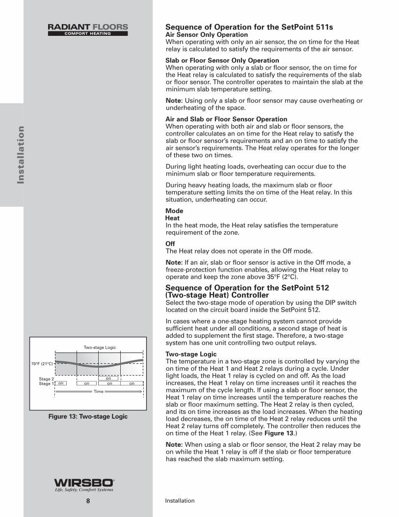
Two-stage LogicThe temperature in a two-stage zone is controlled by varying theon time of the Heat 1 and Heat 2 relays during a cycle. Underlight loads, the Heat 1 relay is cycled on and off. As the loadincreases, the Heat 1 relay on time increases until it reaches themaximum of the cycle length. If using a slab or floor sensor, theHeat 1 relay on time increases until the temperature reaches theslab or floor maximum setting. The Heat 2 relay is then cycled,and its on time increases as the load increases. When the heatingload decreases, the on time of the Heat 2 relay reduces until theHeat 2 relay turns off completely. The controller then reduces theon time of the Heat 1 relay. (See Figure 13.)
Note: When using a slab or floor sensor, the Heat 2 relay may beon while the Heat 1 relay is off if the slab or floor temperaturehas reached the slab maximum setting.
Figure 13: Two-stage Logic

9
Insta
llatio
n
Installation
Air Sensor Only OperationWhen operating with only an air sensor, the on times for the Heat1 and Heat 2 relays are calculated to satisfy the requirements ofthe air sensor.
Slab or Floor Sensor Only OperationWhen operating with only a slab or floor sensor, the on times forthe Heat 1 and Heat 2 relays are calculated to satisfy therequirements of the slab or floor sensor. The SetPoint 512operates to maintain the slab or floor at the minimum slabtemperature setting.
Note: Operating with only a slab or floor sensor can lead toeither overheating or underheating of the space.
Air and Slab or Floor Sensor OperationWhen operating the air and slab or floor sensors concurrently, thecontroller calculates an on time for the Heat 1 relay to satisfy theslab or floor sensor’s requirements and on times for the Heat 1and Heat 2 relays to satisfy the air sensor’s requirements. Thecontroller operates the Heat 1 relay for the longer of these two ontimes.
While the minimum slab or floor temperature is satisfied, the ontimes of the Heat 1 and Heat 2 relays are calculated to satisfy theair temperature requirements.
During heavy loads, the maximum slab or floor temperaturesetting limits the on time of the Heat 1 relay. In this situation, theHeat 2 relay may be on while the Heat 1 relay is off.
Note: During light heating loads, overheating can occur due tothe minimum slab or floor temperature requirements.
ModeHeatIn the Heat mode, the Heat 1 and Heat 2 relays satisfy thetemperature requirement of the zone.
OffThe Heat 1 and Heat 2 relays do not operate in the Off mode.
Note: If an air, slab or floor sensor is active in the Off mode, afreeze-protection function enables, allowing the relays to operateand keep the zone above 35°F (2°C).
Sequence of Operation for the SetPoint 512 (Heatand Cool) ControllerUse the DIP switch located on the circuit board inside thethermostat to select the Heat and Cool mode of operation.
Air Sensor Only OperationWhen operating with only an air sensor, the on times of the Heat1 relay and the Cool relay are calculated to satisfy therequirements of the air sensor.
Slab or Floor Sensor Only OperationWhen operating with only a slab or floor sensor, the on time ofthe Heat 1 relay is calculated to satisfy the requirements of theslab or floor sensor. The SetPoint 512 operates to maintain theslab or floor at the minimum slab temperature setting.
Note: When operating with only a slab or floor sensor, the Coolrelay does not operate. Operating with only a slab or floor sensorcan lead to either overheating or underheating of the space.
Air and Slab or Floor Sensor OperationWhen operating the air and slab or floor sensors concurrently, thecontroller calculates an on time for the Heat 1 relay to satisfy theslab or floor sensor’s requirements and an on time to satisfy theair sensor’s requirements. The Heat 1 relay operates for thelonger of these two on times. The controller also calculates an ontime for the Cool relay to satisfy the air sensor’s requirements. Inthis situation, heating and cooling can happen at the same timeto prevent the space from overheating. This is most likely tooccur when the slab is operating at the slab minimumtemperature.
While the minimum slab temperature is satisfied, the Heat 1 relayon time is calculated to satisfy the air temperature setting.However, the maximum slab temperature setting limits the Heat 1relay on time when the slab temperature becomes too warm. Inthis situation, underheating can occur in the space.
ModeAutoIn the Auto mode, the controller automatically switches betweenheating and cooling the space. However, the heating operationhas priority over the cooling operation. In this mode, theminimum slab or floor temperature is maintained even when thecontroller is cooling the air.
HeatIn the Heat mode, the Heat 1 relay operates to satisfy the heatingtemperature requirement of the zone, and disable the coolingmode.
CoolIn the Cool mode, the Cool relay operates to satisfy the coolingtemperature requirement of the zone, and disable the heatingmode. When using a slab or floor sensor, the slab minimumtemperature is ignored.
OffIn the Off mode, the Heat 1 and Cool relays do not operate.
Note: If an air, slab or floor sensor is active in the Off mode, afreeze-protection function enables, allowing the Heat 1 relay tooperate and keep the zone above 35°F (2°C).
Heating and Cooling InterlockTime Interlock The SetPoint 512 features a Cooling Interlock setting to preventfrequent changes between heating and cooling. Once the Heat 1relay is off for a minimum of one heating cycle or the length ofthe Cooling Interlock, whichever is longer, cooling is permitted.
Temperature Interlock In the Auto mode, the cooling temperature is limited to 3°F(1.5°C) above the heating temperature. If the cooling temperatureis set below the heating temperature, the controller automaticallyadjusts the cooling setpoint.
When operating in the Cool mode, there is no interlock betweenthe heating and cooling temperature.
10
Inst
all
ati
on
Installation
11
Pro
gra
mm
ing
Programming
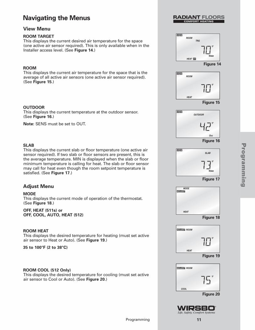
Navigating the Menus
View MenuROOM TARGETThis displays the current desired air temperature for the space(one active air sensor required). This is only available when in theInstaller access level. (See Figure 14.)
ROOMThis displays the current air temperature for the space that is theaverage of all active air sensors (one active air sensor required).(See Figure 15.)
OUTDOORThis displays the current temperature at the outdoor sensor. (See Figure 16.)
Note: SENS must be set to OUT.
SLAB This displays the current slab or floor temperature (one active airsensor required). If two slab or floor sensors are present, this isthe average temperature. MIN is displayed when the slab or floorminimum temperature is calling for heat. The slab or floor sensormay call for heat even though the room setpoint temperature issatisfied. (See Figure 17.)
Adjust MenuMODEThis displays the current mode of operation of the thermostat.(See Figure 18.)
OFF, HEAT (511s) orOFF, COOL, AUTO, HEAT (512)
ROOM HEATThis displays the desired temperature for heating (must set activeair sensor to Heat or Auto). (See Figure 19.)
35 to 100°F (2 to 38°C)
ROOM COOL (512 Only)This displays the desired temperature for cooling (must set activeair sensor to Cool or Auto). (See Figure 20.)
Figure 14
Figure 15
Figure 16
Figure 17
Figure 18
Figure 19
Figure 20
12
Pro
gra
mm
ing
Programming
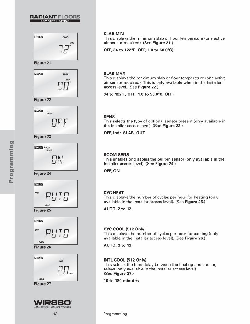
SLAB MINThis displays the minimum slab or floor temperature (one activeair sensor required). (See Figure 21.)
OFF, 34 to 122°F (OFF, 1.0 to 50.0°C)
SLAB MAXThis displays the maximum slab or floor temperature (one activeair sensor required). This is only available when in the Installeraccess level. (See Figure 22.)
34 to 122°F, OFF (1.0 to 50.0°C, OFF)
SENSThis selects the type of optional sensor present (only available inthe Installer access level). (See Figure 23.)
OFF, Indr, SLAB, OUT
ROOM SENSThis enables or disables the built-in sensor (only available in theInstaller access level). (See Figure 24.)
OFF, ON
CYC HEATThis displays the number of cycles per hour for heating (onlyavailable in the Installer access level). (See Figure 25.)
AUTO, 2 to 12
CYC COOL (512 Only)This displays the number of cycles per hour for cooling (onlyavailable in the Installer access level). (See Figure 26.)
AUTO, 2 to 12
INTL COOL (512 Only)This selects the time delay between the heating and coolingrelays (only available in the Installer access level). (See Figure 27.)
10 to 180 minutes
Figure 21
Figure 22
Figure 23
Figure 24
Figure 25
Figure 26
Figure 27
13
Pro
gra
mm
ing
Programming
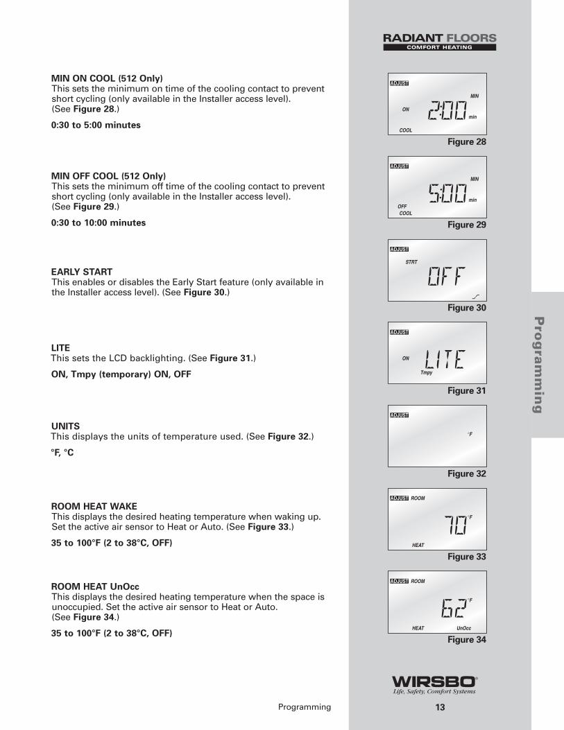
MIN ON COOL (512 Only)This sets the minimum on time of the cooling contact to preventshort cycling (only available in the Installer access level). (See Figure 28.)
0:30 to 5:00 minutes
MIN OFF COOL (512 Only)This sets the minimum off time of the cooling contact to preventshort cycling (only available in the Installer access level). (See Figure 29.)
0:30 to 10:00 minutes
EARLY STARTThis enables or disables the Early Start feature (only available inthe Installer access level). (See Figure 30.)
LITEThis sets the LCD backlighting. (See Figure 31.)
ON, Tmpy (temporary) ON, OFF
UNITSThis displays the units of temperature used. (See Figure 32.)
°F, °C
ROOM HEAT WAKEThis displays the desired heating temperature when waking up.Set the active air sensor to Heat or Auto. (See Figure 33.)
35 to 100°F (2 to 38°C, OFF)
ROOM HEAT UnOccThis displays the desired heating temperature when the space isunoccupied. Set the active air sensor to Heat or Auto. (See Figure 34.)
35 to 100°F (2 to 38°C, OFF)
Figure 28
Figure 29
Figure 30
Figure 31
Figure 32
Figure 33
Figure 34
14
Pro
gra
mm
ing
Programming
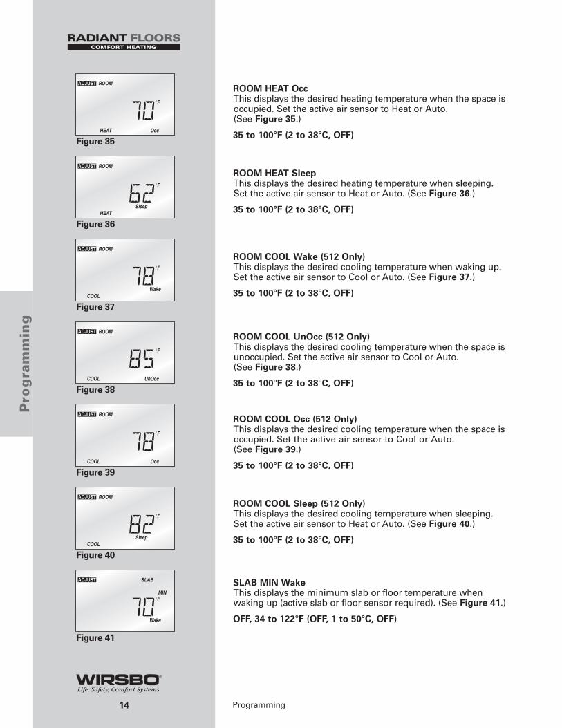
ROOM HEAT OccThis displays the desired heating temperature when the space isoccupied. Set the active air sensor to Heat or Auto. (See Figure 35.)
35 to 100°F (2 to 38°C, OFF)
ROOM HEAT SleepThis displays the desired heating temperature when sleeping. Set the active air sensor to Heat or Auto. (See Figure 36.)
35 to 100°F (2 to 38°C, OFF)
ROOM COOL Wake (512 Only)This displays the desired cooling temperature when waking up.Set the active air sensor to Cool or Auto. (See Figure 37.)
35 to 100°F (2 to 38°C, OFF)
ROOM COOL UnOcc (512 Only)This displays the desired cooling temperature when the space isunoccupied. Set the active air sensor to Cool or Auto. (See Figure 38.)
35 to 100°F (2 to 38°C, OFF)
ROOM COOL Occ (512 Only)This displays the desired cooling temperature when the space isoccupied. Set the active air sensor to Cool or Auto.(See Figure 39.)
35 to 100°F (2 to 38°C, OFF)
ROOM COOL Sleep (512 Only)This displays the desired cooling temperature when sleeping.Set the active air sensor to Heat or Auto. (See Figure 40.)
35 to 100°F (2 to 38°C, OFF)
SLAB MIN WakeThis displays the minimum slab or floor temperature whenwaking up (active slab or floor sensor required). (See Figure 41.)
OFF, 34 to 122°F (OFF, 1 to 50°C, OFF)
Figure 35
Figure 36
Figure 37
Figure 38
Figure 39
Figure 40
Figure 41
15
Pro
gra
mm
ing
Programming
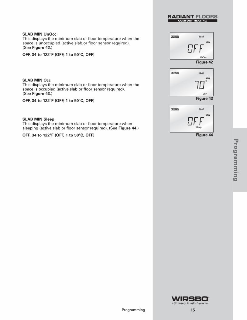
SLAB MIN UnOccThis displays the minimum slab or floor temperature when thespace is unoccupied (active slab or floor sensor required). (See Figure 42.)
OFF, 34 to 122°F (OFF, 1 to 50°C, OFF)
SLAB MIN OccThis displays the minimum slab or floor temperature when thespace is occupied (active slab or floor sensor required). (See Figure 43.)
OFF, 34 to 122°F (OFF, 1 to 50°C, OFF)
SLAB MIN SleepThis displays the minimum slab or floor temperature whensleeping (active slab or floor sensor required). (See Figure 44.)
OFF, 34 to 122°F (OFF, 1 to 50°C, OFF)
Figure 42
Figure 43
Figure 44
16
Trouble
shooti
ng
Troubleshooting
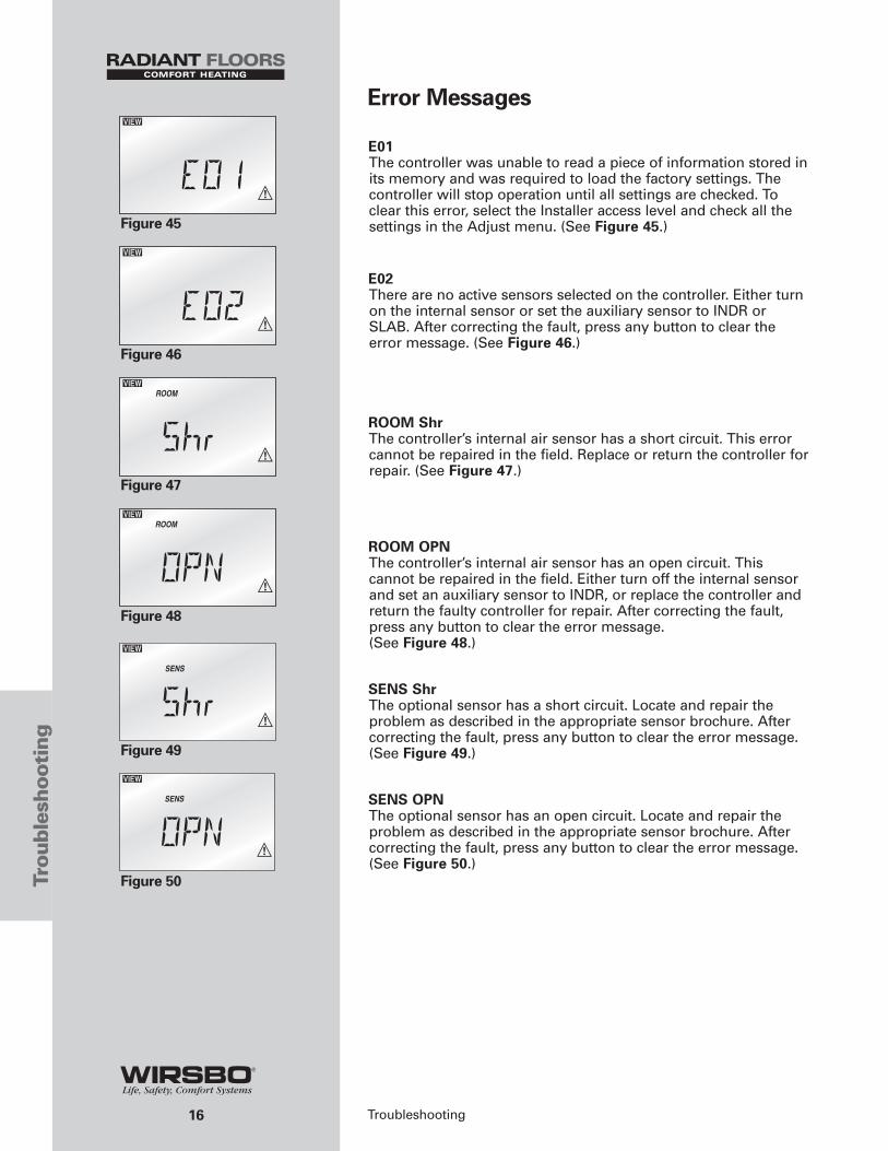
Error Messages
E01The controller was unable to read a piece of information stored inits memory and was required to load the factory settings. Thecontroller will stop operation until all settings are checked. Toclear this error, select the Installer access level and check all thesettings in the Adjust menu. (See Figure 45.)
E02There are no active sensors selected on the controller. Either turnon the internal sensor or set the auxiliary sensor to INDR orSLAB. After correcting the fault, press any button to clear theerror message. (See Figure 46.)
ROOM ShrThe controller’s internal air sensor has a short circuit. This errorcannot be repaired in the field. Replace or return the controller forrepair. (See Figure 47.)
ROOM OPNThe controller’s internal air sensor has an open circuit. Thiscannot be repaired in the field. Either turn off the internal sensorand set an auxiliary sensor to INDR, or replace the controller andreturn the faulty controller for repair. After correcting the fault,press any button to clear the error message. (See Figure 48.)
SENS ShrThe optional sensor has a short circuit. Locate and repair theproblem as described in the appropriate sensor brochure. Aftercorrecting the fault, press any button to clear the error message.(See Figure 49.)
SENS OPNThe optional sensor has an open circuit. Locate and repair theproblem as described in the appropriate sensor brochure. Aftercorrecting the fault, press any button to clear the error message.(See Figure 50.)
Figure 49
Figure 50
Figure 45
Figure 46
Figure 47
Figure 48
17
Tech
nic
al
Data
Technical Data
Technical Data
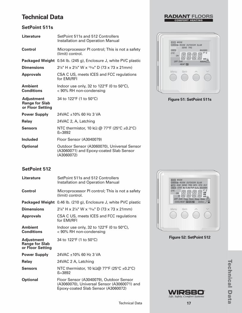
SetPoint 511s
Literature SetPoint 511s and 512 Controllers Installation and Operation Manual
Control Microprocessor PI control; This is not a safety(limit) control.
Packaged Weight 0.54 lb. (245 g), Enclosure J, white PVC plastic
Dimensions 2⁷⁄₈" H x 2⁷⁄₈" W x ¹³⁄₁₆" D (73 x 73 x 21mm)
Approvals CSA C US, meets ICES and FCC regulationsfor EMI/RFI
Ambient Indoor use only, 32 to 122°F (0 to 50°C),Conditions < 90% RH non-condensing
Adjustment 34 to 122°F (1 to 50°C)Range for Slab or Floor Setting
Power Supply 24VAC ±10% 60 Hz 3 VA
Relay 24VAC 2, A, Latching
Sensors NTC thermistor, 10 kΩ @ 77°F (25°C ±0.2°C)ß=3892
Included Floor Sensor (A3040079)
Optional Outdoor Sensor (A3060070), Universal Sensor(A3060071) and Epoxy-coated Slab Sensor(A3060072)
SetPoint 512
Literature SetPoint 511s and 512 Controllers Installation and Operation Manual
Control Microprocessor PI control; This is not a safety(limit) control.
Packaged Weight 0.46 lb. (210 g), Enclosure J, white PVC plastic
Dimensions 2⁷⁄₈" H x 2⁷⁄₈" W x ¹³⁄₁₆" D (73 x 73 x 21mm)
Approvals CSA C US, meets ICES and FCC regulationsfor EMI/RFI
Ambient Indoor use only, 32 to 122°F (0 to 50°C), Conditions < 90% RH non-condensing
Adjustment 34 to 122°F (1 to 50°C) Range for Slabor Floor Setting
Power Supply 24VAC ±10% 60 Hz 3 VA
Relay 24VAC 2 A, Latching
Sensors NTC thermistor, 10 kΩ@ 77°F (25°C ±0.2°C)ß=3892
Optional Floor Sensor (A3040079), Outdoor Sensor(A3060070), Universal Sensor (A3060071) andEpoxy-coated Slab Sensor (A3060072)
Figure 51: SetPoint 511s
Figure 52: SetPoint 512

Notes
No
tes
Notes:
18

Notes
Notes:
19
No
tes

Inside Back Page

www.wirsbo.com
Uponor Wirsbo, Inc.5925 148th Street WestApple Valley, MN 55124
Tel: (800) 321-4739Fax: (952) 891-1409
www.wirsbo.com
Copyright © 2005 Uponor Wirsbo, Printed in the United States SP511s&512MAN_8_05